JP3131102U - 電動工具のバッテリー - Google Patents
電動工具のバッテリー Download PDFInfo
- Publication number
- JP3131102U JP3131102U JP2007000711U JP2007000711U JP3131102U JP 3131102 U JP3131102 U JP 3131102U JP 2007000711 U JP2007000711 U JP 2007000711U JP 2007000711 U JP2007000711 U JP 2007000711U JP 3131102 U JP3131102 U JP 3131102U
- Authority
- JP
- Japan
- Prior art keywords
- active unit
- battery
- cap
- top surface
- electric tool
- Prior art date
- Legal status (The legal status is an assumption and is not a legal conclusion. Google has not performed a legal analysis and makes no representation as to the accuracy of the status listed.)
- Expired - Fee Related
Links
Images




Classifications
-
- H—ELECTRICITY
- H01—ELECTRIC ELEMENTS
- H01G—CAPACITORS; CAPACITORS, RECTIFIERS, DETECTORS, SWITCHING DEVICES, LIGHT-SENSITIVE OR TEMPERATURE-SENSITIVE DEVICES OF THE ELECTROLYTIC TYPE
- H01G2/00—Details of capacitors not covered by a single one of groups H01G4/00-H01G11/00
- H01G2/02—Mountings
- H01G2/04—Mountings specially adapted for mounting on a chassis
-
- H—ELECTRICITY
- H02—GENERATION; CONVERSION OR DISTRIBUTION OF ELECTRIC POWER
- H02J—ELECTRIC POWER NETWORKS; CIRCUIT ARRANGEMENTS OR SYSTEMS FOR SUPPLYING OR DISTRIBUTING ELECTRIC POWER; SYSTEMS FOR STORING ELECTRIC ENERGY
- H02J7/00—Circuit arrangements for charging or discharging batteries or for supplying loads from batteries
- H02J7/70—Circuit arrangements for charging or discharging batteries or for supplying loads from batteries characterised by the mechanical construction
-
- H—ELECTRICITY
- H01—ELECTRIC ELEMENTS
- H01M—PROCESSES OR MEANS, e.g. BATTERIES, FOR THE DIRECT CONVERSION OF CHEMICAL ENERGY INTO ELECTRICAL ENERGY
- H01M10/00—Secondary cells; Manufacture thereof
- H01M10/60—Heating or cooling; Temperature control
- H01M10/61—Types of temperature control
- H01M10/613—Cooling or keeping cold
-
- H—ELECTRICITY
- H01—ELECTRIC ELEMENTS
- H01G—CAPACITORS; CAPACITORS, RECTIFIERS, DETECTORS, SWITCHING DEVICES, LIGHT-SENSITIVE OR TEMPERATURE-SENSITIVE DEVICES OF THE ELECTROLYTIC TYPE
- H01G11/00—Hybrid capacitors, i.e. capacitors having different positive and negative electrodes; Electric double-layer [EDL] capacitors; Processes for the manufacture thereof or of parts thereof
- H01G11/10—Multiple hybrid or EDL capacitors, e.g. arrays or modules
-
- H—ELECTRICITY
- H01—ELECTRIC ELEMENTS
- H01G—CAPACITORS; CAPACITORS, RECTIFIERS, DETECTORS, SWITCHING DEVICES, LIGHT-SENSITIVE OR TEMPERATURE-SENSITIVE DEVICES OF THE ELECTROLYTIC TYPE
- H01G11/00—Hybrid capacitors, i.e. capacitors having different positive and negative electrodes; Electric double-layer [EDL] capacitors; Processes for the manufacture thereof or of parts thereof
- H01G11/14—Arrangements or processes for adjusting or protecting hybrid or EDL capacitors
- H01G11/18—Arrangements or processes for adjusting or protecting hybrid or EDL capacitors against thermal overloads, e.g. heating, cooling or ventilating
-
- H—ELECTRICITY
- H01—ELECTRIC ELEMENTS
- H01G—CAPACITORS; CAPACITORS, RECTIFIERS, DETECTORS, SWITCHING DEVICES, LIGHT-SENSITIVE OR TEMPERATURE-SENSITIVE DEVICES OF THE ELECTROLYTIC TYPE
- H01G11/00—Hybrid capacitors, i.e. capacitors having different positive and negative electrodes; Electric double-layer [EDL] capacitors; Processes for the manufacture thereof or of parts thereof
- H01G11/78—Cases; Housings; Encapsulations; Mountings
- H01G11/82—Fixing or assembling a capacitive element in a housing, e.g. mounting electrodes, current collectors or terminals in containers or encapsulations
-
- H—ELECTRICITY
- H01—ELECTRIC ELEMENTS
- H01G—CAPACITORS; CAPACITORS, RECTIFIERS, DETECTORS, SWITCHING DEVICES, LIGHT-SENSITIVE OR TEMPERATURE-SENSITIVE DEVICES OF THE ELECTROLYTIC TYPE
- H01G2/00—Details of capacitors not covered by a single one of groups H01G4/00-H01G11/00
- H01G2/08—Cooling arrangements; Heating arrangements; Ventilating arrangements
-
- H—ELECTRICITY
- H01—ELECTRIC ELEMENTS
- H01G—CAPACITORS; CAPACITORS, RECTIFIERS, DETECTORS, SWITCHING DEVICES, LIGHT-SENSITIVE OR TEMPERATURE-SENSITIVE DEVICES OF THE ELECTROLYTIC TYPE
- H01G2/00—Details of capacitors not covered by a single one of groups H01G4/00-H01G11/00
- H01G2/10—Housing; Encapsulation
-
- H—ELECTRICITY
- H01—ELECTRIC ELEMENTS
- H01G—CAPACITORS; CAPACITORS, RECTIFIERS, DETECTORS, SWITCHING DEVICES, LIGHT-SENSITIVE OR TEMPERATURE-SENSITIVE DEVICES OF THE ELECTROLYTIC TYPE
- H01G9/00—Electrolytic capacitors, rectifiers, detectors, switching devices, light-sensitive or temperature-sensitive devices; Processes of their manufacture
- H01G9/0003—Protection against electric or thermal overload; cooling arrangements; means for avoiding the formation of cathode films
-
- H—ELECTRICITY
- H01—ELECTRIC ELEMENTS
- H01G—CAPACITORS; CAPACITORS, RECTIFIERS, DETECTORS, SWITCHING DEVICES, LIGHT-SENSITIVE OR TEMPERATURE-SENSITIVE DEVICES OF THE ELECTROLYTIC TYPE
- H01G9/00—Electrolytic capacitors, rectifiers, detectors, switching devices, light-sensitive or temperature-sensitive devices; Processes of their manufacture
- H01G9/004—Details
- H01G9/08—Housing; Encapsulation
-
- H—ELECTRICITY
- H01—ELECTRIC ELEMENTS
- H01G—CAPACITORS; CAPACITORS, RECTIFIERS, DETECTORS, SWITCHING DEVICES, LIGHT-SENSITIVE OR TEMPERATURE-SENSITIVE DEVICES OF THE ELECTROLYTIC TYPE
- H01G9/00—Electrolytic capacitors, rectifiers, detectors, switching devices, light-sensitive or temperature-sensitive devices; Processes of their manufacture
- H01G9/28—Structural combinations of electrolytic capacitors, rectifiers, detectors, switching devices with other electric components not covered by this subclass
-
- H—ELECTRICITY
- H01—ELECTRIC ELEMENTS
- H01M—PROCESSES OR MEANS, e.g. BATTERIES, FOR THE DIRECT CONVERSION OF CHEMICAL ENERGY INTO ELECTRICAL ENERGY
- H01M10/00—Secondary cells; Manufacture thereof
- H01M10/60—Heating or cooling; Temperature control
- H01M10/62—Heating or cooling; Temperature control specially adapted for specific applications
- H01M10/623—Portable devices, e.g. mobile telephones, cameras or pacemakers
- H01M10/6235—Power tools
-
- H—ELECTRICITY
- H01—ELECTRIC ELEMENTS
- H01M—PROCESSES OR MEANS, e.g. BATTERIES, FOR THE DIRECT CONVERSION OF CHEMICAL ENERGY INTO ELECTRICAL ENERGY
- H01M10/00—Secondary cells; Manufacture thereof
- H01M10/60—Heating or cooling; Temperature control
- H01M10/65—Means for temperature control structurally associated with the cells
- H01M10/656—Means for temperature control structurally associated with the cells characterised by the type of heat-exchange fluid
- H01M10/6561—Gases
- H01M10/6563—Gases with forced flow, e.g. by blowers
-
- H—ELECTRICITY
- H01—ELECTRIC ELEMENTS
- H01M—PROCESSES OR MEANS, e.g. BATTERIES, FOR THE DIRECT CONVERSION OF CHEMICAL ENERGY INTO ELECTRICAL ENERGY
- H01M10/00—Secondary cells; Manufacture thereof
- H01M10/60—Heating or cooling; Temperature control
- H01M10/65—Means for temperature control structurally associated with the cells
- H01M10/656—Means for temperature control structurally associated with the cells characterised by the type of heat-exchange fluid
- H01M10/6561—Gases
- H01M10/6566—Means within the gas flow to guide the flow around one or more cells, e.g. manifolds, baffles or other barriers
-
- H—ELECTRICITY
- H01—ELECTRIC ELEMENTS
- H01M—PROCESSES OR MEANS, e.g. BATTERIES, FOR THE DIRECT CONVERSION OF CHEMICAL ENERGY INTO ELECTRICAL ENERGY
- H01M50/00—Constructional details or processes of manufacture of the non-active parts of electrochemical cells other than fuel cells, e.g. hybrid cells
- H01M50/20—Mountings; Secondary casings or frames; Racks, modules or packs; Suspension devices; Shock absorbers; Transport or carrying devices; Holders
- H01M50/204—Racks, modules or packs for multiple batteries or multiple cells
- H01M50/207—Racks, modules or packs for multiple batteries or multiple cells characterised by their shape
- H01M50/213—Racks, modules or packs for multiple batteries or multiple cells characterised by their shape adapted for cells having curved cross-section, e.g. round or elliptic
-
- H—ELECTRICITY
- H01—ELECTRIC ELEMENTS
- H01M—PROCESSES OR MEANS, e.g. BATTERIES, FOR THE DIRECT CONVERSION OF CHEMICAL ENERGY INTO ELECTRICAL ENERGY
- H01M50/00—Constructional details or processes of manufacture of the non-active parts of electrochemical cells other than fuel cells, e.g. hybrid cells
- H01M50/20—Mountings; Secondary casings or frames; Racks, modules or packs; Suspension devices; Shock absorbers; Transport or carrying devices; Holders
- H01M50/244—Secondary casings; Racks; Suspension devices; Carrying devices; Holders characterised by their mounting method
-
- H—ELECTRICITY
- H01—ELECTRIC ELEMENTS
- H01M—PROCESSES OR MEANS, e.g. BATTERIES, FOR THE DIRECT CONVERSION OF CHEMICAL ENERGY INTO ELECTRICAL ENERGY
- H01M50/00—Constructional details or processes of manufacture of the non-active parts of electrochemical cells other than fuel cells, e.g. hybrid cells
- H01M50/20—Mountings; Secondary casings or frames; Racks, modules or packs; Suspension devices; Shock absorbers; Transport or carrying devices; Holders
- H01M50/271—Lids or covers for the racks or secondary casings
-
- H—ELECTRICITY
- H01—ELECTRIC ELEMENTS
- H01M—PROCESSES OR MEANS, e.g. BATTERIES, FOR THE DIRECT CONVERSION OF CHEMICAL ENERGY INTO ELECTRICAL ENERGY
- H01M50/00—Constructional details or processes of manufacture of the non-active parts of electrochemical cells other than fuel cells, e.g. hybrid cells
- H01M50/20—Mountings; Secondary casings or frames; Racks, modules or packs; Suspension devices; Shock absorbers; Transport or carrying devices; Holders
- H01M50/296—Mountings; Secondary casings or frames; Racks, modules or packs; Suspension devices; Shock absorbers; Transport or carrying devices; Holders characterised by terminals of battery packs
-
- H—ELECTRICITY
- H01—ELECTRIC ELEMENTS
- H01M—PROCESSES OR MEANS, e.g. BATTERIES, FOR THE DIRECT CONVERSION OF CHEMICAL ENERGY INTO ELECTRICAL ENERGY
- H01M6/00—Primary cells; Manufacture thereof
- H01M6/50—Methods or arrangements for servicing or maintenance, e.g. for maintaining operating temperature
- H01M6/5038—Heating or cooling of cells or batteries
-
- H—ELECTRICITY
- H01—ELECTRIC ELEMENTS
- H01M—PROCESSES OR MEANS, e.g. BATTERIES, FOR THE DIRECT CONVERSION OF CHEMICAL ENERGY INTO ELECTRICAL ENERGY
- H01M50/00—Constructional details or processes of manufacture of the non-active parts of electrochemical cells other than fuel cells, e.g. hybrid cells
- H01M50/10—Primary casings; Jackets or wrappings
- H01M50/102—Primary casings; Jackets or wrappings characterised by their shape or physical structure
- H01M50/107—Primary casings; Jackets or wrappings characterised by their shape or physical structure having curved cross-section, e.g. round or elliptic
-
- H—ELECTRICITY
- H02—GENERATION; CONVERSION OR DISTRIBUTION OF ELECTRIC POWER
- H02J—ELECTRIC POWER NETWORKS; CIRCUIT ARRANGEMENTS OR SYSTEMS FOR SUPPLYING OR DISTRIBUTING ELECTRIC POWER; SYSTEMS FOR STORING ELECTRIC ENERGY
- H02J7/00—Circuit arrangements for charging or discharging batteries or for supplying loads from batteries
- H02J7/70—Circuit arrangements for charging or discharging batteries or for supplying loads from batteries characterised by the mechanical construction
- H02J7/751—Circuit arrangements for charging or discharging batteries or for supplying loads from batteries characterised by the mechanical construction concerning the insertion or the connection of the batteries
-
- Y—GENERAL TAGGING OF NEW TECHNOLOGICAL DEVELOPMENTS; GENERAL TAGGING OF CROSS-SECTIONAL TECHNOLOGIES SPANNING OVER SEVERAL SECTIONS OF THE IPC; TECHNICAL SUBJECTS COVERED BY FORMER USPC CROSS-REFERENCE ART COLLECTIONS [XRACs] AND DIGESTS
- Y02—TECHNOLOGIES OR APPLICATIONS FOR MITIGATION OR ADAPTATION AGAINST CLIMATE CHANGE
- Y02E—REDUCTION OF GREENHOUSE GAS [GHG] EMISSIONS, RELATED TO ENERGY GENERATION, TRANSMISSION OR DISTRIBUTION
- Y02E60/00—Enabling technologies; Technologies with a potential or indirect contribution to GHG emissions mitigation
- Y02E60/10—Energy storage using batteries
-
- Y—GENERAL TAGGING OF NEW TECHNOLOGICAL DEVELOPMENTS; GENERAL TAGGING OF CROSS-SECTIONAL TECHNOLOGIES SPANNING OVER SEVERAL SECTIONS OF THE IPC; TECHNICAL SUBJECTS COVERED BY FORMER USPC CROSS-REFERENCE ART COLLECTIONS [XRACs] AND DIGESTS
- Y02—TECHNOLOGIES OR APPLICATIONS FOR MITIGATION OR ADAPTATION AGAINST CLIMATE CHANGE
- Y02E—REDUCTION OF GREENHOUSE GAS [GHG] EMISSIONS, RELATED TO ENERGY GENERATION, TRANSMISSION OR DISTRIBUTION
- Y02E60/00—Enabling technologies; Technologies with a potential or indirect contribution to GHG emissions mitigation
- Y02E60/13—Energy storage using capacitors
Landscapes
- Engineering & Computer Science (AREA)
- Power Engineering (AREA)
- Chemical Kinetics & Catalysis (AREA)
- Chemical & Material Sciences (AREA)
- Electrochemistry (AREA)
- General Chemical & Material Sciences (AREA)
- Microelectronics & Electronic Packaging (AREA)
- Manufacturing & Machinery (AREA)
- Life Sciences & Earth Sciences (AREA)
- Biophysics (AREA)
- Secondary Cells (AREA)
- Battery Mounting, Suspending (AREA)
- Medicines That Contain Protein Lipid Enzymes And Other Medicines (AREA)
- Charge And Discharge Circuits For Batteries Or The Like (AREA)
- Portable Power Tools In General (AREA)
Abstract
【解決手段】ケース10、電池本体20、キャップ30及びアクティブユニットセット40を備える。ケースには収容室11と開口部12とを有する。電池本体には、コンデンサー21と導電端片22とを有する。キャップには、頂面と底面32とを有し、上方に外部の電子設備と結合するための嵌合部34、第一穿孔33及びスライド溝35を有する。アクティブユニットセットには、アクティブユニット41とスプリング、スライド部411及び第二穿孔413を有する。アクティブユニットはスライド溝に沿って第一位置と第二位置との間を移動可能である。
【選択図】図1
Description
多くの充電器は放熱装置を有するが、放熱装置は充電器のみに放熱作用を生じるため、バッテリーそのものの温度を下げ・効率よく放熱を行うことができず、温度が高すぎて電池を焼損してしまうか、充電中の温度が高すぎて使用寿命を短縮してしまうという事態が起こる。
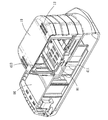
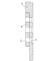
図1から図7に示すように、本実施例による電動工具のバッテリー100には、ケース10、電池本体20、キャップ30及びアクティブユニットセット40を備える。
ケース10は内部に収容室11を有し、ケース10の一側には収容室11に繋がる開口部12を有し、ケース10の他側には収容室11に繋がる若干の孔13を有する。またケース10は二つの外側に外部の充電器または電動工具と嵌合するための弾性のある係止ユニット14を別々に有する。
以上は本考案の実施例による電動工具のバッテリー100の部品についての説明であるた。続いて組立方法と使用の際の特徴とについて説明する。
Claims (5)
- 内部に収容室と、収容室と外部とを接続する開口部とを有するケースと、
収容室内に配置され、かつ外部の電子設備と電気的に導通する導電端片を有する電池本体と、
頂面、底面、及び頂面と底面とを貫通する第一穿孔とスライド溝とを有し、頂面はケースの開口部にあてがうように設けられ、底面は上方に外部の電子設備と結合される嵌合部を有するキャップと、
アクティブユニットとスプリングとを有し、アクティブユニットは収容室内に位置するようキャップの頂面に配置され、かつスライド溝に入り込むスライド部と、頂面と底面とが貫通される第二穿孔とを有し、アクティブユニットはスライド部によりスライド溝に沿い第一位置と第二位置の間を往復移動可能であり、スプリングは両端がアクティブユニットとキャップとに別々に突き当てられるアクティブユニットセットと、を備え、
アクティブユニットがスプリングの弾力を受けて第一位置に維持されている場合、第一穿孔と第二穿孔とは非連続状態となり、外力を介してスライド部が押されることによりアクティブユニットが第二位置に移動される場合、第一穿孔と第二穿孔とは連続状態となることを特徴とする電動工具のバッテリー。 - ケースは一側に収容室と繋がる孔を有することを特徴とする請求項1に記載の電動工具のバッテリー。
- 電池本体にはコンデンサーと導電端片とを有し、導電端片はコンデンサーと電気的に接続され、かつ外部の電子設備と電気的に導通するようにキャップから露出するように設けられることを特徴とする請求項1に記載の電動工具のバッテリー。
- アクティブユニットは、一側にスプリングの一端に突き当てられる突状柱を有することを特徴とする請求項1に記載の電動工具のバッテリー。
- スライド部は、一部分がキャップの底面から露出するように設けられることを特徴とする請求項1に記載の電動工具のバッテリー。
Priority Applications (7)
| Application Number | Priority Date | Filing Date | Title |
|---|---|---|---|
| CNB200710002481XA CN100533847C (zh) | 2007-01-29 | 2007-01-29 | 电动工具的电池 |
| JP2007000711U JP3131102U (ja) | 2007-01-29 | 2007-02-08 | 電動工具のバッテリー |
| AU2007100398A AU2007100398A4 (en) | 2007-01-29 | 2007-05-17 | Battery Module for Power Hand Tool |
| US11/802,117 US7993769B2 (en) | 2007-01-29 | 2007-05-21 | Battery module for power hand tool |
| GB0709743A GB2449442B (en) | 2007-01-29 | 2007-05-22 | Battery module for power hand tool |
| DE102007024320A DE102007024320B4 (de) | 2007-01-29 | 2007-05-24 | Batteriemodul für ein elektrisches Handwerkzeug |
| CA2590127A CA2590127C (en) | 2007-01-29 | 2007-05-28 | Battery module for power hand tool |
Applications Claiming Priority (7)
| Application Number | Priority Date | Filing Date | Title |
|---|---|---|---|
| CNB200710002481XA CN100533847C (zh) | 2007-01-29 | 2007-01-29 | 电动工具的电池 |
| JP2007000711U JP3131102U (ja) | 2007-01-29 | 2007-02-08 | 電動工具のバッテリー |
| AU2007100398A AU2007100398A4 (en) | 2007-01-29 | 2007-05-17 | Battery Module for Power Hand Tool |
| US11/802,117 US7993769B2 (en) | 2007-01-29 | 2007-05-21 | Battery module for power hand tool |
| GB0709743A GB2449442B (en) | 2007-01-29 | 2007-05-22 | Battery module for power hand tool |
| DE102007024320A DE102007024320B4 (de) | 2007-01-29 | 2007-05-24 | Batteriemodul für ein elektrisches Handwerkzeug |
| CA2590127A CA2590127C (en) | 2007-01-29 | 2007-05-28 | Battery module for power hand tool |
Publications (1)
| Publication Number | Publication Date |
|---|---|
| JP3131102U true JP3131102U (ja) | 2007-04-19 |
Family
ID=54256405
Family Applications (1)
| Application Number | Title | Priority Date | Filing Date |
|---|---|---|---|
| JP2007000711U Expired - Fee Related JP3131102U (ja) | 2007-01-29 | 2007-02-08 | 電動工具のバッテリー |
Country Status (7)
| Country | Link |
|---|---|
| US (1) | US7993769B2 (ja) |
| JP (1) | JP3131102U (ja) |
| CN (1) | CN100533847C (ja) |
| AU (1) | AU2007100398A4 (ja) |
| CA (1) | CA2590127C (ja) |
| DE (1) | DE102007024320B4 (ja) |
| GB (1) | GB2449442B (ja) |
Cited By (1)
| Publication number | Priority date | Publication date | Assignee | Title |
|---|---|---|---|---|
| JP2024082676A (ja) * | 2022-12-08 | 2024-06-20 | パナソニックIpマネジメント株式会社 | 電動工具及び電池パック |
Families Citing this family (12)
| Publication number | Priority date | Publication date | Assignee | Title |
|---|---|---|---|---|
| JP2011155821A (ja) * | 2010-01-28 | 2011-08-11 | Sanyo Electric Co Ltd | 充電器 |
| KR102150679B1 (ko) | 2018-03-13 | 2020-09-01 | 주식회사 엘지화학 | 배터리 모듈, 이러한 배터리 모듈을 포함하는 배터리 팩 및 이러한 배터리 팩을 포함하는 자동차 |
| USD929334S1 (en) | 2019-09-05 | 2021-08-31 | Techtronic Cordless Gp | Electrical interface |
| USD929338S1 (en) | 2019-09-05 | 2021-08-31 | Techtronic Cordless Gp | Electrical interface |
| USD953268S1 (en) | 2019-09-05 | 2022-05-31 | Techtronic Cordless Gp | Electrical interface |
| USD1013634S1 (en) | 2019-09-05 | 2024-02-06 | Techtronic Cordless Gp | Battery pack |
| USD929336S1 (en) | 2019-09-05 | 2021-08-31 | Techtronic Cordless Gp | Electrical interface |
| USD929337S1 (en) | 2019-09-05 | 2021-08-31 | Techtronic Cordless Gp | Electrical interface |
| USD929339S1 (en) | 2019-09-05 | 2021-08-31 | Techtronic Cordless Gp | Electrical interface |
| USD929335S1 (en) | 2019-09-05 | 2021-08-31 | Techtronic Cordless Gp | Electrical interface |
| US11973237B2 (en) | 2020-02-25 | 2024-04-30 | Milwaukee Electric Tool Corporation | Battery pack |
| TWI801086B (zh) * | 2022-01-10 | 2023-05-01 | 達宇電能科技股份有限公司 | 電池組、電池組連接結構及電池組串接 |
Family Cites Families (6)
| Publication number | Priority date | Publication date | Assignee | Title |
|---|---|---|---|---|
| US6455186B1 (en) * | 1998-03-05 | 2002-09-24 | Black & Decker Inc. | Battery cooling system |
| JP3652634B2 (ja) * | 2001-10-05 | 2005-05-25 | 本田技研工業株式会社 | 高圧電装部品の冷却構造 |
| GB2392002B (en) * | 2002-08-12 | 2004-10-13 | Choon Nang Elec Appl Mfy Ltd | Rechargeable battery pack |
| CN2629225Y (zh) * | 2003-08-08 | 2004-07-28 | 北京有色金属研究总院 | 一种电池箱体 |
| CN2645860Y (zh) * | 2003-08-11 | 2004-10-06 | 车王电子股份有限公司 | 电动工具 |
| EP1780865B1 (en) * | 2005-10-31 | 2017-02-22 | Black & Decker, Inc. | Thermal management system for a battery pack |
-
2007
- 2007-01-29 CN CNB200710002481XA patent/CN100533847C/zh not_active Expired - Fee Related
- 2007-02-08 JP JP2007000711U patent/JP3131102U/ja not_active Expired - Fee Related
- 2007-05-17 AU AU2007100398A patent/AU2007100398A4/en not_active Ceased
- 2007-05-21 US US11/802,117 patent/US7993769B2/en not_active Expired - Fee Related
- 2007-05-22 GB GB0709743A patent/GB2449442B/en not_active Expired - Fee Related
- 2007-05-24 DE DE102007024320A patent/DE102007024320B4/de not_active Expired - Fee Related
- 2007-05-28 CA CA2590127A patent/CA2590127C/en not_active Expired - Fee Related
Cited By (1)
| Publication number | Priority date | Publication date | Assignee | Title |
|---|---|---|---|---|
| JP2024082676A (ja) * | 2022-12-08 | 2024-06-20 | パナソニックIpマネジメント株式会社 | 電動工具及び電池パック |
Also Published As
| Publication number | Publication date |
|---|---|
| US20080292910A1 (en) | 2008-11-27 |
| GB2449442B (en) | 2009-11-04 |
| CN100533847C (zh) | 2009-08-26 |
| GB0709743D0 (en) | 2007-06-27 |
| DE102007024320B4 (de) | 2011-12-29 |
| US7993769B2 (en) | 2011-08-09 |
| GB2449442A (en) | 2008-11-26 |
| CA2590127C (en) | 2010-09-21 |
| CA2590127A1 (en) | 2008-11-28 |
| CN101237073A (zh) | 2008-08-06 |
| AU2007100398A4 (en) | 2007-06-21 |
| DE102007024320A1 (de) | 2008-11-27 |
Similar Documents
| Publication | Publication Date | Title |
|---|---|---|
| JP3131102U (ja) | 電動工具のバッテリー | |
| JP3131098U (ja) | 電動工具のバッテリー | |
| TW200940281A (en) | A power tool having a mating battery | |
| US20080166629A1 (en) | Battery receptacle having two pairs of anode and cathode terminals | |
| EP1826841A2 (en) | Charging apparatus | |
| US7492582B2 (en) | Portable computer with detachable solar cell module | |
| TW201423325A (zh) | 可調式電池盒及其應用的電子裝置 | |
| CN210778754U (zh) | 一种锂电池防爆保护结构 | |
| WO2018126439A1 (zh) | 动力电池顶盖结构、动力电池及电池模组 | |
| EP3531530B1 (en) | Compression-type charging device | |
| CN118448939B (zh) | 连接器及储能设备 | |
| CN102487172B (zh) | 可变换插头方向的电源转换器 | |
| CN100530763C (zh) | 外壳及使用这种外壳的锂二次电池 | |
| CN211958799U (zh) | 一种车辆电源转换器 | |
| CN211907765U (zh) | 一种充电连接结构和一种充电工作灯 | |
| CN213816572U (zh) | 一种防尘型插座 | |
| CN204011513U (zh) | 一种锂电池包 | |
| TW200829382A (en) | Battery of power tool | |
| CN211484366U (zh) | 一种充电座和吸尘器 | |
| CN222582083U (zh) | 一种pd电源保护装置 | |
| CN208368775U (zh) | 车载充电器及其弹片结构 | |
| KR101033821B1 (ko) | 차량용 시가라이터 | |
| CN222503922U (zh) | 点火器 | |
| CN115312986B (en) | Soft package lithium battery formation tab contact device and formation equipment constructed by same | |
| CN211065070U (zh) | 一种便携式电子烟具 |
Legal Events
| Date | Code | Title | Description |
|---|---|---|---|
| R150 | Certificate of patent or registration of utility model |
Free format text: JAPANESE INTERMEDIATE CODE: R150 |
|
| FPAY | Renewal fee payment (event date is renewal date of database) |
Free format text: PAYMENT UNTIL: 20100328 Year of fee payment: 3 |
|
| FPAY | Renewal fee payment (event date is renewal date of database) |
Free format text: PAYMENT UNTIL: 20110328 Year of fee payment: 4 |
|
| FPAY | Renewal fee payment (event date is renewal date of database) |
Free format text: PAYMENT UNTIL: 20130328 Year of fee payment: 6 |
|
| FPAY | Renewal fee payment (event date is renewal date of database) |
Free format text: PAYMENT UNTIL: 20140328 Year of fee payment: 7 |
|
| R250 | Receipt of annual fees |
Free format text: JAPANESE INTERMEDIATE CODE: R250 |
|
| LAPS | Cancellation because of no payment of annual fees |