JP3124635U - Pneumatic tire - Google Patents
Pneumatic tire Download PDFInfo
- Publication number
- JP3124635U JP3124635U JP2006004538U JP2006004538U JP3124635U JP 3124635 U JP3124635 U JP 3124635U JP 2006004538 U JP2006004538 U JP 2006004538U JP 2006004538 U JP2006004538 U JP 2006004538U JP 3124635 U JP3124635 U JP 3124635U
- Authority
- JP
- Japan
- Prior art keywords
- depth
- sipe
- tire
- uneven wear
- pneumatic tire
- Prior art date
- Legal status (The legal status is an assumption and is not a legal conclusion. Google has not performed a legal analysis and makes no representation as to the accuracy of the status listed.)
- Expired - Fee Related
Links
Images

Landscapes
- Tires In General (AREA)
Abstract
【課題】溝の深さを測定することなく偏摩耗の発生を容易に確認することのできる空気入りタイヤを提供する。
【解決手段】トレッド部1にタイヤ幅方向に均一な深さで延びる複数のサイプ1cを互いにタイヤ周方向に等間隔で設けるとともに、各サイプ1cをタイヤ周方向一方に向かって徐々に深さが異なるように形成したので、各サイプ1cを偏摩耗が生じた部分から徐々に消滅させていくことができ、各サイプ1cの残存状態を目視により確認することにより、偏摩耗の発生を容易に確認することができる。これにより、デプスゲージを用いて溝の深さを測定しなくとも、偏摩耗の発生及びその進行度合いを容易に確認することができ、偏摩耗の早期発見及びその対応をユーザーに促すことができる。
【選択図】図3There is provided a pneumatic tire in which occurrence of uneven wear can be easily confirmed without measuring a groove depth.
SOLUTION: A plurality of sipes 1c extending at a uniform depth in the tire width direction are provided on the tread portion 1 at equal intervals in the tire circumferential direction, and each sipe 1c is gradually increased in depth toward one side in the tire circumferential direction. Since they are formed differently, each sipe 1c can be gradually disappeared from the portion where uneven wear has occurred, and the occurrence of uneven wear can be easily confirmed by visually checking the remaining state of each sipe 1c. can do. Thereby, even if it does not measure the depth of a groove | channel using a depth gauge, generation | occurrence | production and the progression degree of partial wear can be confirmed easily, and a user can be encouraged for early detection of the partial wear and its response.
[Selection] Figure 3
Description
本考案は、例えば乗用車、トラック、バス等に用いられる空気入りタイヤに関するものである。 The present invention relates to a pneumatic tire used in, for example, passenger cars, trucks, buses and the like.
一般に、この種の空気入りタイヤにおいては、車両からの荷重、車両におけるタイヤの位置、不適正な空気圧など、種々の原因により偏摩耗が発生することが知られている。このような偏摩耗はタイヤの寿命や性能を低下させるため、定期的に点検してタイヤのローテーションや空気圧管理等を行うことにより、偏摩耗の解消または低減を図ることが望ましい。通常、偏摩耗の確認にはデプスゲージが用いられ(例えば、特許文献1参照。)、デプスゲージによってトレッド部の溝の深さを測定することにより偏摩耗発生の有無を確認している。
しかしながら、デプスゲージを用いて偏摩耗の確認をするためには、作業者が手作業によりトレッド部の複数箇所に対して溝の深さを測定しなければならず、確認作業に多大な手間と時間を要することから、偏摩耗の確認を怠り易いという問題点があった。 However, in order to check uneven wear using a depth gauge, the operator must manually measure the groove depth at multiple locations on the tread, which requires a lot of labor and time. Therefore, there is a problem that it is easy to neglect the confirmation of uneven wear.
本考案は前記問題点に鑑みてなされたものであり、その目的とするところは、溝の深さを測定することなく偏摩耗の発生を容易に確認することのできる空気入りタイヤを提供することにある。 The present invention has been made in view of the above problems, and an object of the present invention is to provide a pneumatic tire that can easily confirm the occurrence of uneven wear without measuring the depth of the groove. It is in.
本考案は前記目的を達成するために、タイヤ外周面にトレッド部を有する空気入りタイヤにおいて、前記トレッド部にタイヤ幅方向に均一な深さで延びる複数のサイプを互いにタイヤ周方向に間隔をおいて設け、各サイプをタイヤ周方向一方に向かって徐々に深さが異なるように設けている。 In order to achieve the above object, the present invention provides a pneumatic tire having a tread portion on the outer peripheral surface of the tire. Each sipe is provided so that the depth is gradually different toward one side in the tire circumferential direction.
これにより、トレッド部の偏摩耗を生ずると、各サイプが偏摩耗を生じた部分から徐々に消滅していくことから、各サイプの残存状態を目視により確認することにより、偏摩耗の発生を容易に確認することができる。 As a result, when uneven wear occurs in the tread part, each sipe gradually disappears from the part where the uneven wear occurs, so it is easy to generate uneven wear by visually checking the remaining state of each sipe. Can be confirmed.
本考案によれば、偏摩耗の発生を目視により確認することができるので、デプスゲージを用いて溝の深さを測定しなくとも、偏摩耗の発生及びその進行度合いを容易に確認することができ、偏摩耗の早期発見及びその対応をユーザーに促すことができる。 According to the present invention, since the occurrence of uneven wear can be visually confirmed, the occurrence of uneven wear and its progress can be easily confirmed without measuring the groove depth using a depth gauge. In addition, it is possible to prompt the user for early detection of uneven wear and its response.
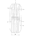
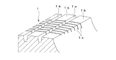
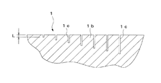
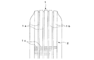
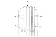
図1乃至図6は本考案の一実施形態を示すもので、図1は空気入りタイヤの正面図、図2はその部分正面断面図、図3はその要部拡大斜視図、図4はその要部側面断面図、図5及び6は偏摩耗状態を示す部分正面図である。 1 to 6 show an embodiment of the present invention. FIG. 1 is a front view of a pneumatic tire, FIG. 2 is a partial front sectional view thereof, FIG. 3 is an enlarged perspective view of an essential portion thereof, and FIG. FIG. 5 and FIG. 6 are partial front views showing a partial wear state.
この空気入りタイヤは、外周面側に形成されるトレッド部1と、幅方向両側に形成されるサイドウォール部2と、サイドウォール部2のタイヤ径方向内側に形成されるビード部3とを備え、ビード部3内にはタイヤ周方向に延びる環状のビードコア3aが埋設されている。トレッド部1にはタイヤ周方向に延びる複数の主溝1aが設けられ、各主溝1a間にはリブパターン1bが形成されている。尚、トレッド部1の副溝は図示を省略してある。また、トレッド部1にはタイヤ幅方向に均一な深さで延びる複数のサイプ1c(例えば、幅1mm以下の細溝または切り込み)が互いにタイヤ周方向に等間隔で設けられ、各サイプ1cはタイヤ周方向一方に向かって徐々に深くなるように形成されている。この場合、各サイプ1cはトレッド幅Wの全体に亘って設けられるとともに、その深さLの最小を1.0mm以上1.5mm以下とし、深さLが1.0mm以上1.5mmの範囲のうち所定深さずつ深くなるように形成されている。例えば、各サイプ1cは、深さLの最小が1.2mmで、深さLが1.2mmずつ深くなるように形成される。尚、このようなサイプ群は、例えばトレッド部1のタイヤ周方向4箇所に設けられている。
The pneumatic tire includes a
以上のように構成された空気入りタイヤにおいては、トレッド部1が摩耗すると、トレッド部1の肉厚の減少に伴って各サイプ1cの深さが徐々に浅くなり、初期の深さLの小さいものから順に消滅する。この場合、例えばタイヤ幅方向の一方が片減りする偏摩耗を生じた場合には、図5に示すように各サイプ1cがタイヤ幅方向の一端側から消滅していき、タイヤ幅方向の中央側が摩耗する偏摩耗を生じた場合には、図6に示すように各サイプ1cがタイヤ幅方向中央側から消滅していくため、このような偏摩耗を目視により容易に確認することができる。その際、各サイプ1cはタイヤ周方向一方に向かって徐々に深くなっているので、偏摩耗の進行度合いも目視により容易に確認することができる。尚、各サイプ1cの最小深さ及び深さの差は、1.0mmよりも小さいと各サイプ1cの残存状態の偏りが明瞭にあらわれなくなり、1.5mmよりも大きいと偏摩耗の進行度合いを容易に判別できなくなるため、各サイプ1cの深さLの最小を1.0mm以上1.5mm以下とし、深さLが1.0mm以上1.5mm以下の範囲のうち所定深さずつ深くなるように形成することが好ましい。
In the pneumatic tire configured as described above, when the
このように、本実施形態によれば、トレッド部1にタイヤ幅方向に均一な深さで延びる複数のサイプ1cを互いにタイヤ周方向に等間隔で設けるとともに、各サイプ1cをタイヤ周方向一方に向かって徐々に深くなるように形成したので、各サイプ1cを偏摩耗が生じた部分から徐々に消滅させていくことができ、各サイプ1cの残存状態を目視により確認することにより、偏摩耗の発生を容易に確認することができる。これにより、デプスゲージを用いて溝の深さを測定しなくとも、偏摩耗の発生及びその進行度合いを容易に確認することができ、偏摩耗の早期発見及びその対応をユーザーに促すことができる。
Thus, according to the present embodiment, the
この場合、各サイプ1cをトレッド幅Wの全体に亘って設けたので、トレッド部1の幅方向何れの位置においても、サイプ1cによる偏摩耗の確認を行うことができる。
In this case, since each sipe 1c is provided over the entire tread width W, it is possible to check the partial wear due to the sipe 1c at any position in the width direction of the
また、各サイプ1cの深さLの最小を1.0mm以上1.5mm以下とし、その深さLが1.0mm以上1.5mmの範囲のうち所定深さずつ深くなるように形成したので、各サイプ1cの残存状態の偏りと偏摩耗の進行度合いを明瞭に判別することができ、実用化に際して極めて有利である。 In addition, since the minimum depth L of each sipe 1c is 1.0 mm or more and 1.5 mm or less, the depth L is formed so as to be deeper by a predetermined depth in a range of 1.0 mm or more and 1.5 mm. The deviation of the remaining state of each sipe 1c and the degree of progress of uneven wear can be clearly discriminated, which is extremely advantageous for practical use.
尚、前記実施形態では、主にトラックやバス等の重荷重用タイヤに用いられるリブパターン1bを有するものを示したが、本考案は乗用車等に用いられるブロックパターンを有するものにも適用することができる。 In addition, although the said embodiment showed what has the rib pattern 1b mainly used for heavy load tires, such as a truck and a bus, this invention is applicable also to what has a block pattern used for a passenger car etc. it can.
1…トレッド部、1c…サイプ。 1 ... tread part, 1c ... sipe.
Claims (3)
前記トレッド部にタイヤ幅方向に均一な深さで延びる複数のサイプを互いにタイヤ周方向に等間隔で設け、
各サイプをタイヤ周方向一方に向かって徐々に深くなるように設けた
ことを特徴とする空気入りタイヤ。 In a pneumatic tire having a tread portion on the outer peripheral surface of the tire,
A plurality of sipes extending at a uniform depth in the tire width direction are provided in the tread portion at equal intervals in the tire circumferential direction,
A pneumatic tire characterized in that each sipe is provided so as to gradually become deeper toward one side in the tire circumferential direction.
ことを特徴とする請求項1記載の空気入りタイヤ。 The pneumatic tire according to claim 1, wherein each sipe is formed over the entire tread width.
ことを特徴とする請求項1または2記載の空気入りタイヤ。 The minimum depth of each sipe is 1.0 mm or more and 1.5 mm or less, and the depth is formed so as to increase by a predetermined depth within a range of 1.0 mm or more and 1.5 mm. The pneumatic tire according to 1 or 2.
Priority Applications (1)
| Application Number | Priority Date | Filing Date | Title |
|---|---|---|---|
| JP2006004538U JP3124635U (en) | 2006-06-12 | 2006-06-12 | Pneumatic tire |
Applications Claiming Priority (1)
| Application Number | Priority Date | Filing Date | Title |
|---|---|---|---|
| JP2006004538U JP3124635U (en) | 2006-06-12 | 2006-06-12 | Pneumatic tire |
Publications (1)
| Publication Number | Publication Date |
|---|---|
| JP3124635U true JP3124635U (en) | 2006-08-24 |
Family
ID=43474553
Family Applications (1)
| Application Number | Title | Priority Date | Filing Date |
|---|---|---|---|
| JP2006004538U Expired - Fee Related JP3124635U (en) | 2006-06-12 | 2006-06-12 | Pneumatic tire |
Country Status (1)
| Country | Link |
|---|---|
| JP (1) | JP3124635U (en) |
Cited By (2)
| Publication number | Priority date | Publication date | Assignee | Title |
|---|---|---|---|---|
| JP2511367Y2 (en) | 1990-08-31 | 1996-09-25 | 大日本スクリーン製造株式会社 | Cascade type cleaning device |
| CN116214292A (en) * | 2023-02-20 | 2023-06-06 | 青岛双星轮胎工业有限公司 | A tire tread grinding method and device for correlation between tire pattern deep groove and performance |
-
2006
- 2006-06-12 JP JP2006004538U patent/JP3124635U/en not_active Expired - Fee Related
Cited By (2)
| Publication number | Priority date | Publication date | Assignee | Title |
|---|---|---|---|---|
| JP2511367Y2 (en) | 1990-08-31 | 1996-09-25 | 大日本スクリーン製造株式会社 | Cascade type cleaning device |
| CN116214292A (en) * | 2023-02-20 | 2023-06-06 | 青岛双星轮胎工业有限公司 | A tire tread grinding method and device for correlation between tire pattern deep groove and performance |
Similar Documents
| Publication | Publication Date | Title |
|---|---|---|
| EP3594024B1 (en) | Tire | |
| US11267294B2 (en) | Tire | |
| JP2009143450A (en) | Pneumatic tire | |
| JP2012171591A (en) | Tire | |
| JP5791427B2 (en) | Heavy duty pneumatic tire | |
| JP2010012978A (en) | Pneumatic tire | |
| JP2005193815A (en) | Pneumatic tire | |
| JP4973020B2 (en) | Pneumatic tire | |
| JP3124635U (en) | Pneumatic tire | |
| US10576788B2 (en) | Tire | |
| JP2009096255A (en) | Pneumatic tire | |
| JP4970893B2 (en) | Pneumatic tire | |
| JP4813230B2 (en) | Pneumatic tire | |
| JP2009083769A (en) | Pneumatic tire | |
| JP5256624B2 (en) | Pneumatic tire | |
| JP2014213650A (en) | Aircraft tire | |
| CN108146153B (en) | Pneumatic tire | |
| JP2010083304A (en) | Pneumatic tire | |
| JP2006062584A (en) | Pneumatic tire | |
| JP2008037223A (en) | Pneumatic tire | |
| JP2005138609A (en) | Pneumatic tire | |
| JP6411007B2 (en) | Pneumatic tire | |
| JP5041466B2 (en) | Pneumatic tire | |
| KR100592061B1 (en) | Heavy Duty Pneumatic Tire | |
| JP2008307971A (en) | Pneumatic tire |
Legal Events
| Date | Code | Title | Description |
|---|---|---|---|
| R150 | Certificate of patent or registration of utility model |
Free format text: JAPANESE INTERMEDIATE CODE: R150 |
|
| FPAY | Renewal fee payment (event date is renewal date of database) |
Free format text: PAYMENT UNTIL: 20090802 Year of fee payment: 3 |
|
| FPAY | Renewal fee payment (event date is renewal date of database) |
Free format text: PAYMENT UNTIL: 20100802 Year of fee payment: 4 |
|
| FPAY | Renewal fee payment (event date is renewal date of database) |
Free format text: PAYMENT UNTIL: 20110802 Year of fee payment: 5 |
|
| FPAY | Renewal fee payment (event date is renewal date of database) |
Free format text: PAYMENT UNTIL: 20110802 Year of fee payment: 5 |
|
| FPAY | Renewal fee payment (event date is renewal date of database) |
Free format text: PAYMENT UNTIL: 20110802 Year of fee payment: 5 |
|
| FPAY | Renewal fee payment (event date is renewal date of database) |
Free format text: PAYMENT UNTIL: 20110802 Year of fee payment: 5 |
|
| LAPS | Cancellation because of no payment of annual fees |