JP3121663U - Barrier-free drainage piping system for dental clinics - Google Patents
Barrier-free drainage piping system for dental clinics Download PDFInfo
- Publication number
- JP3121663U JP3121663U JP2006001969U JP2006001969U JP3121663U JP 3121663 U JP3121663 U JP 3121663U JP 2006001969 U JP2006001969 U JP 2006001969U JP 2006001969 U JP2006001969 U JP 2006001969U JP 3121663 U JP3121663 U JP 3121663U
- Authority
- JP
- Japan
- Prior art keywords
- drainage
- liquid
- pipe
- tank
- separator
- Prior art date
- Legal status (The legal status is an assumption and is not a legal conclusion. Google has not performed a legal analysis and makes no representation as to the accuracy of the status listed.)
- Expired - Fee Related
Links
Images
Landscapes
- Dental Tools And Instruments Or Auxiliary Dental Instruments (AREA)
Abstract
【課題】 診療室排水障害区域のバリアフリー化を行う排水処理系配管の改良。
【解決手段】 治療ユニット8からの治療排液を、うがい液ととも集める排水分離器1において、排液を気液分離した後に液排出弁1cの開作動制御によって、分離器の排水吐出管9から機械的接触無しに排水を受け入れる排水タンク4に貯留し、タンクにはポンプ5を内設し、逆勾配区域1Bにはフレキシブルチューブを含む曲部形成配管材6を配管接続して、タンク貯留液をその液位制御により作動するポンプが既設排水管3まで排液を圧送する強制排水ルートを構成した。
【選択図】図1PROBLEM TO BE SOLVED: To improve wastewater treatment system piping for barrier-free in a drainage obstacle area of a medical office.
In a drainage separator 1 that collects treatment drainage from a treatment unit 8 together with gargle, after the drainage is separated into gas and liquid, the drainage discharge pipe 9 of the separator is controlled by opening operation control of a liquid discharge valve 1c. Is stored in a drain tank 4 that receives drainage without mechanical contact, a pump 5 is installed in the tank, and a curved portion forming piping material 6 including a flexible tube is connected to the reverse gradient section 1B to store the tank. A forced drainage route was constructed in which a pump operating the liquid by controlling the liquid level pumped the drainage to the existing drainage pipe 3.
[Selection] Figure 1
Description
本考案は、歯科用チェアユニットから出る排液の排水技術に係り、特に建物建造時に排水処理の設計対象外であった室内に、歯科診療室を開設するに当たり、診療予定区域に逆勾配区域や出入口障害物などが介在して排水配管ができない問題点を解決し、あるいは問題解決のために設けられる配管収納用の二重床を基本的に不要化して、歯科診療室内に歩行障害の生じないバリアフリー化を計る排水配管装置に関するものである。 The present invention relates to the drainage technology for the drainage from the dental chair unit. Solves the problem of drainage piping not being possible due to obstacles at entrances and exits, or basically eliminates the need for a double floor for storing piping provided to solve the problem, so that walking obstacles do not occur in the dental clinic The present invention relates to a drainage piping device that is barrier-free.
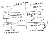
歯科診療室からは、うがい液排出のほか、治療処置時にバキュームエアや加圧空気などの介在空気を用いるために、空気、処置時発生液、歯垢など、気液固が混在した一様でない排液が出る。その治療排液は、空気輸送が出来るので、図2に示すように、、歯科診療室外の他室に設置する機械室に排水分離器1を配設し、歯科用チェアユニット8(以下、治療ユニットという)を排水発生元とし、前記介在空気と共にそこから排水分離器1に導水し、この貯留中に、空気分は真空ポンプにより分離、回収され、排液分は該排水分離器内に溜められ、器内内設の液位計1aが貯留排液の設定上位液位を検知すると、制御器1bが作動して液排出弁1c開を動作し、既設排水管7へ排水、さらに配管接続する敷設排水管3へと排水される。排水継続によって排水分離器1の液位計1aが設定下位液位を検知すると、制御器1bが液排出弁1cを閉動作して、排水操作は終了する。これらの貯留、排水の交互制御操作は排水分離器1により繰り返される。一方、うがい液排水のためには、同図に示すように、順勾配の排水配管が行えない場合、別途行ううがい液排水管2のために、特設する二重床の下部に順勾配排水配管を施工して、既設排水配管まで延長する配管を行う。
なお、液排出弁1cにはフロート弁の使用が一般的であり、排水分離器1とその運転制御操作は公知である。In addition to gargle drainage from the dental clinic, intervening air such as vacuum air and pressurized air is used during treatment procedures, so air, liquid generated during treatment, plaque, etc. are not uniform. Drainage comes out. Since the treatment drainage can be pneumatically transported, as shown in FIG. 2, a
Note that a float valve is generally used as the liquid discharge valve 1c, and the
ここに歯科医院をテナント向け建物の貸室に開設する場合、診療室に転用する部屋は、居室や寝室またはオフィスに設定され、当初は給排水設備を設けない貸室に開設するので、排水配管敷設勾配が逆勾配であったり、治療ユニットに必要な新規排水配管が、扉配置個所を横切ることになり、あるいは隣室など別室に排水分離器を配置できない機械室を借り出せない場合がある。こうしたケースでは、二重床改造の他に、新設床高に応じた扉廻りの改造を行うので、改造によって出来る凹凸床面は、当然、治療者の歩行障害になる。
人が集まる地理的条件の良いテナント向け建物内に、歯科診療室の新設を計っても、排水問題により開設出来なかったり、改造費用が過大で困難になる例がある。また無理な排水配管によって、患者にとってのバリアフリー環境が作れないという欠点があった。When opening a dental clinic in a rental room in a building for tenants here, the room to be diverted to the clinic is set in a living room, bedroom, or office, and initially opens in a rental room that does not have water supply and drainage facilities. In some cases, the slope is reverse, new drainage pipes required for the treatment unit cross the door placement location, or it is not possible to borrow a machine room where a drainage separator cannot be placed in another room such as the adjacent room. In such a case, in addition to the double floor remodeling, the doors are remodeled according to the newly installed floor height, so that the uneven floor surface that is formed by the remodeling naturally becomes an obstacle for the therapist to walk.
There are cases where even if a new dental clinic is set up in a tenant building with good geographical conditions where people gather, it cannot be opened due to a drainage problem, or the cost of remodeling becomes excessive and difficult. In addition, there was a drawback that a barrier-free environment could not be created for patients due to unreasonable drainage piping.
前記問題解決の参考例に、崖下家屋から出る生活排水を崖上の既設下水道へ排水する解決策として、家屋と同地盤内に汚水枡を設け、家から順勾配でその桝まで導水し、枡に溜めた排水を崖上へポンプアップする排水装置(特許文献1)や、家屋内の浴槽から浴槽外設置ポンプにより槽内湯水を吸い出して、外へ排水する提案(特許文献2)等がある。
これら従来技術を適用して、汚水枡の代わりに排水分離器1を用い、この中にポンプを内設し、制御器に連動して排水を行うポンプアップ方式が考えられる。しかし、後述するように、歯科用の治療ユニットが排出する二系統の排水設備や、扱う気液混在排液の同時処理、かつ頻繁に少量の排液の供給と停止が繰り返されて貯留する排水分離器の扱い、貯留量と排水貯留時間の不安定性に対応して、それにマッチするポンプ選定は困難である。またポンプ作動時と治療ユニット作動時とが重複する場合に、治療器操作に支障をきたす。さらに排水分離器にポンプを内設する場合、治療ユニットとは機械的接続状態にあり、ポンプ作動音が治療ユニットから洩れ、患者の治療環境に悪影響が出るなどの問題がある。In the reference example for solving the problem, as a solution to drain the domestic wastewater from the cliff house to the existing sewer on the cliff, a sewage basin is installed in the same ground as the house, and water is led from the house to the basin with a forward slope. There is a drainage device (Patent Document 1) that pumps up the drainage accumulated in the ridge to the cliff, a proposal to suck out the hot water in the tank from the bathtub inside the house using the pump installed outside the bathtub, and drain it to the outside (Patent Document 2), etc. is there.
Applying these conventional techniques, a pump-up system is conceivable in which a
ところで歯科の治療ユニットが断続的に発生する排液量は、1人1回当たり平均0.4〜0.6リットルの排液量、1時間2〜3人の患者を診療した場合、1日8時間で合計約10リットル(特許文献3)、貸室診療室に使われる標準大きさの排水分離器(220ψ×300H、槽底設置高約280、排液流入VP管25φ)の容量は約3.5リットル、25ψVP管は内容積が管長1m当たり約0.9リットルになる。従って排水発生元の排液発生状態に応じて排水分離器に貯留され、そこにポンプを内設して稼働させると、ポンプ動作は、極めて短時間運転して排出終了し、その稼働は頻繁なON−OFFを繰り返し、その際のポンプ発生衝撃は、バキュームエア消費時の騒音とともに治療ユニットに対し悪影響がでる。この状態を行わないで済むような内設可能の汎用のポンプはない。
解決しようとする問題点は、うがい液と治療排液の排水処理が別途に行われる点であり、分離器から以降に排水する際に、強制排出用にポンプを別設する場合、ポンプ作動が起こす副次的発生障害が、治療ユニットまで伝達して治療や患者に悪影響を及ぼす点であり、排水分離器を機械室設備のある診療室外に設置しなければならない点であり、他方では排水の逆勾配条件下での排水配管を付設するに当たって、改造床を作ることによって患者利用の床に凹凸が生じて床のバリアフリー化ができない点である。 The problem to be solved is that the gargle and treatment drainage are drained separately, and when the pump is separately installed for forced drainage when draining from the separator later, the pump operation is not possible. A secondary outbreak that occurs is that it is transmitted to the treatment unit and adversely affects treatment and the patient, and a drain separator must be installed outside the clinic where the machine room equipment is located. When attaching drainage pipes under reverse gradient conditions, making a modified floor creates irregularities on the patient's floor, making it impossible to make the floor barrier-free.
本考案は、排水分離器と機械的に接続しないポンプを、新設する排水タンク内に設置して、うがい液と共に治療排液を、排水分離器を介して排水タンクへ配管の不連続状にて案内し、その後、ポンプアップ操作により一括して強制排水したことを最も主要な特徴とする。 In the present invention, a pump that is not mechanically connected to the drain separator is installed in a newly installed drain tank, and the treatment drainage together with the gargle is sent to the drain tank via the drain separator in a discontinuous manner of piping. The main feature is that it was guided and then forcedly drained in a batch by pump-up operation.
本考案は、排水分離器の排水と排水停止の制御操作と、一方、排水タンクのポンプ作動制御とはそれぞれ独立しているので、一方の操作が他方の動作を阻害することはない。
また治療ユニットに接続する排水分離器と排水タンクを隔離して配設し、稼働する排水ポンプを水中に設置したので、ポンプの作動音も衝撃も治療ユニット系に全く伝わらない。
そして排水タンクから既設排水管への排水をポンプアップ排水し、その排水配管のポンプ吐出側導水排水管にフレキシブルチューブを含む曲部形成配管材を用いてい。従って、扉の上框上部までの立ち上げ配管が簡便にでき、その上框部配管ルートを乗り越えさせる排水操作をポンプ吐出圧により容易にでき、床下に配管代を設ける床面改造の必要性がない。Since the present invention is independent of the control operation of drainage and drainage stop of the drain separator and the pump operation control of the drainage tank, one operation does not hinder the other operation.
In addition, since the drainage separator and drainage tank connected to the treatment unit are separated and the operating drainage pump is installed in the water, the pump operating noise and impact are not transmitted to the treatment unit system at all.
And the drainage from the drainage tank to the existing drainage pipe is pumped up, and the curved portion forming piping material including the flexible tube is used for the pump discharge side water conduit drainage pipe of the drainage pipe. Therefore, the start-up piping up to the upper ridge of the door can be simplified, drainage operation over the upper ridge piping route can be facilitated by the pump discharge pressure, and there is a need to remodel the floor to provide piping charges under the floor. Absent.
逆勾配配管を余儀なくされる診療室の排水装置を設ける際に、床面のバリアフリー化を実施するという目的を、排水分離器と、ポンプ内設の排水タンクとを切り離して構成したことにより実現した。 Realized the purpose of making the floor surface barrier-free by separating the drain separator and the drain tank inside the pump when installing a drainage device in the clinic that requires reverse gradient piping. did.
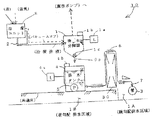
図1は、本考案装置の1実施例を示す概要図であって、1〜3および7、8は、図2と同様である。2は治療排液を移送する排水管に接続するうがい液排水管、4は、タンク内液位計4aが設定上位液位L1を検知すると制御器4bが作動して水中ポンプ5(以下、ポンプという)をON作動し、同設定下位液位L2を検知すると、該制御器の作動によってポンプ5をOFF作動させ、貯留、排水の交互制御操作を繰り返す排水タンクであって、その貯留排水は、排水分離器1下部に垂設する排水吐出管9の、束縛自由状態の開放端から受ける。6は、排水処理ルート上の障害物30を上方に迂回配管するフレキシブルチューブを含む曲部形成配管材を用いた導水排水管であって、ポンプ5と敷設排水管7とを配管接続して、既設排水管3に排水するものである。
ここに、図示するのは迂回配管を大きく行う極端な例であって、設置するポンプ5は、扉の上框を越える障害ルートのない通常例の多くは、逆勾配抵抗は少なく、水頭抵抗が200mm以下なら実用仕様を満たし、浴室用湯水汲み出し用のポンプで差し支えない。
なお1Aは、該敷設排水管が順勾配で配管できる順勾配排水区域、1Bは、順勾配排水不能区域であって、かつ本発明装置によって排水工事が実施できる区域である。FIG. 1 is a schematic view showing one embodiment of the device of the present invention, and 1-3, 7, and 8 are the same as those in FIG. 2 is a gargle drainage pipe connected to the drainage pipe for transferring the treatment drainage, and 4 is a submersible pump 5 (hereinafter referred to as a pump) when the controller 4b is activated when the tank level gauge 4a detects the set upper liquid level L1. Is turned on, and when the set lower liquid level L2 is detected, the pump 5 is turned off by the operation of the controller, and the storage and drainage are repeatedly controlled alternately. It receives from the open end of the drainage discharge pipe 9 suspended in the lower part of the
Here, the illustrated example is an extreme example in which the bypass piping is greatly increased. The pump 5 to be installed has a low reverse gradient resistance and a head resistance in many of the normal examples in which there is no obstacle route beyond the top of the door. If it is 200 mm or less, it satisfies the practical specifications, and a pump for pumping out hot water for bathrooms can be used.
In addition, 1A is a forward slope drainage area where the laid drainage pipe can be piped in a forward slope, 1B is an area where forward slope drainage is impossible, and an area where drainage work can be performed by the device of the present invention.
このように排水分離器1に排水吐出管9を、排水タンク4の液面上方の中空空間に設けたので、該排水吐出管は貯液充満時には封水と液排出弁1cによって閉じられ、その開放時には、排水タンクに移送された貯液がポンプ5を水封するので、排水タンク4が発生させる作動状態を、治療ユニット8へ伝達してしまう事例は全く起こらず、従って排水分離器1内で行われる動作は、独立的に操作、制御され、従って治療ユニットへ、ポンプ5が与える影響は皆無となる。そして排水タンク4の大きさは、ポンプ5による強制排水により排水分離器1の大きさに合わせて形状を変えらて小型に出来、かつ振動、騒音などの副次的弊害が生じないので、診療室内に設置できる。 Thus, since the drainage discharge pipe 9 is provided in the hollow space above the liquid level of the drainage tank 4, the drainage discharge pipe is closed by the sealed water and the liquid discharge valve 1c when the liquid is filled, At the time of opening, the storage liquid transferred to the drainage tank seals the pump 5, so there is no case where the operating state generated by the drainage tank 4 is transmitted to the
本考案装置を、一見、逆勾配の排水配管を布設せざるを得ないので、目的の業務を行えないと部屋の使用を諦めるような、空圧、加圧水洗浄など多様な媒体を駆使する技術の展示場や特設実験場向けに応用できるものであり、あるいは少量排水形の給排水設備や臨時排水配管装置としても、転用ないし適用できる。 At first glance, the device of the present invention must be installed with a reverse-graded drainage pipe, so it is possible to use various media such as air pressure and pressurized water washing that would give up the use of the room if the intended work cannot be performed. It can be applied to exhibition halls and special experiment sites, or can be diverted or applied to small-drainage water supply / drainage facilities and temporary drainage piping equipment.
1 排水分離器
2 うがい液排水管
3 既設排水管
4 排水タンク
5 ポンプ
6 曲部形成配管材を用いた導水排水管(フレキシブルチューブを含む)
7 敷設(または固定)排水管
8 治療ユニット(歯科用チェアユニット)
9 排水吐出管
10 バリアフリー化排水配管装置
30 障害物DESCRIPTION OF
7 Laying (or fixed)
9 Drainage discharge pipe 10 Barrier-free
Claims (1)
Priority Applications (1)
| Application Number | Priority Date | Filing Date | Title |
|---|---|---|---|
| JP2006001969U JP3121663U (en) | 2006-02-20 | 2006-02-20 | Barrier-free drainage piping system for dental clinics |
Applications Claiming Priority (1)
| Application Number | Priority Date | Filing Date | Title |
|---|---|---|---|
| JP2006001969U JP3121663U (en) | 2006-02-20 | 2006-02-20 | Barrier-free drainage piping system for dental clinics |
Publications (1)
| Publication Number | Publication Date |
|---|---|
| JP3121663U true JP3121663U (en) | 2006-05-25 |
Family
ID=43471763
Family Applications (1)
| Application Number | Title | Priority Date | Filing Date |
|---|---|---|---|
| JP2006001969U Expired - Fee Related JP3121663U (en) | 2006-02-20 | 2006-02-20 | Barrier-free drainage piping system for dental clinics |
Country Status (1)
| Country | Link |
|---|---|
| JP (1) | JP3121663U (en) |
-
2006
- 2006-02-20 JP JP2006001969U patent/JP3121663U/en not_active Expired - Fee Related
Similar Documents
| Publication | Publication Date | Title |
|---|---|---|
| CN101765393A (en) | Accelerated tub drain | |
| JP6888801B2 (en) | Mobile flush toilet and flush toilet system | |
| JP2000074260A (en) | Piping structure for drainage in dwellings | |
| JP3121663U (en) | Barrier-free drainage piping system for dental clinics | |
| JPH08226147A (en) | Water storage type water pipe device and water supply device using the same | |
| JP6372976B2 (en) | Drainage pipe structure and drainage pipe construction method | |
| JP5625197B1 (en) | Disaster prevention flush toilet system | |
| JPH11280129A (en) | Unit house plumbing structure | |
| JP3108548U (en) | Dental drainage separator | |
| CN204662623U (en) | Hidden drainage system in shower stall | |
| JP4445139B2 (en) | Railway building drainage device and railroad building drainage method | |
| JP2019027113A (en) | Flush toilet and flush toilet system | |
| JP2004360442A (en) | Sealing water supplying method for drain trap, flow passage opening/closing device and sealing water supplying device for drain trap used for the method | |
| JP2915322B2 (en) | Drainage facilities for apartment buildings and storage tanks used for them | |
| JP4611662B2 (en) | Vacuum valve unit | |
| JP2018178660A (en) | Flush toilet and flush toilet system | |
| CN206408734U (en) | Full-automatic filter backwashing sewage water lifting means | |
| CN220521472U (en) | A household bath water recycling device | |
| JP2005113559A (en) | Wastewater pumping equipment and method | |
| CN202338021U (en) | Full-automatic environment-friendly sewage lifting device | |
| JP2002302976A (en) | Siphon type drain system | |
| JP2006082067A (en) | Piping for waste water treatment system for dental chair unit | |
| CN211286817U (en) | Bathroom substructure | |
| JP6781423B1 (en) | Disaster prevention flush toilet system | |
| JP4055842B2 (en) | Piping structure in low-rise housing |
Legal Events
| Date | Code | Title | Description |
|---|---|---|---|
| R150 | Certificate of patent or registration of utility model |
Free format text: JAPANESE INTERMEDIATE CODE: R150 |
|
| LAPS | Cancellation because of no payment of annual fees |