JP3107008U - Member mounting structure - Google Patents
Member mounting structure Download PDFInfo
- Publication number
- JP3107008U JP3107008U JP2004004637U JP2004004637U JP3107008U JP 3107008 U JP3107008 U JP 3107008U JP 2004004637 U JP2004004637 U JP 2004004637U JP 2004004637 U JP2004004637 U JP 2004004637U JP 3107008 U JP3107008 U JP 3107008U
- Authority
- JP
- Japan
- Prior art keywords
- mounting
- burring
- housing
- fan holder
- mounting portion
- Prior art date
- Legal status (The legal status is an assumption and is not a legal conclusion. Google has not performed a legal analysis and makes no representation as to the accuracy of the status listed.)
- Expired - Fee Related
Links
Images


Abstract
【課題】バーリングを形成できない筐体に対してファンホルダを的確に取り付けることができる部材取付構造を提供する。
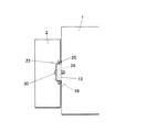
【解決手段】バーリングが形成できない厚さの被取付部13を有する筐体1の表面側にファンホルダ2を取り付ける部材取付構造において、ファンホルダ2は、バーリング24が形成された取付部23を備え、被取付部13を、ファンホルダ2が取り付けられる筐体1の取付面に対して外側に突出させて、取付面との間に取付部23を挿入自在な間隙ができるように形成し、取付部23の側縁を取付部23の裏側に折り曲げてバーリング24の先端部よりも厚さ方向に突出する折曲部を形成し、取付部23を間隙に挿入してファンホルダ2と筐体1を連結した。
【選択図】図1
A member mounting structure capable of accurately mounting a fan holder to a casing in which burring cannot be formed is provided.
In a member mounting structure in which a fan holder is attached to the surface side of a housing having a mounted portion having a thickness that cannot form a burring, the fan holder includes a mounting portion in which a burring is formed. The mounting portion 13 is protruded outward with respect to the mounting surface of the housing 1 to which the fan holder 2 is mounted, and the mounting portion 23 is formed so as to be freely inserted between the mounting surface and mounting. The side edge of the portion 23 is bent to the back side of the mounting portion 23 to form a bent portion that protrudes in the thickness direction from the tip portion of the burring 24, and the mounting portion 23 is inserted into the gap to insert the fan holder 2 and the housing 1. Were concatenated.
[Selection] Figure 1
Description
本考案は、部材取付構造に関する。 The present invention relates to a member mounting structure.
従来、DVDプレイヤー等の電子機器においては、長時間の使用に伴い電子部品が高温となる。そこで、電子機器の筐体に冷却ファンや放熱板を設け、この冷却ファンや放熱板により電子部品を空冷することができるようになっている。 Conventionally, in an electronic device such as a DVD player, an electronic component becomes hot as it is used for a long time. Therefore, a cooling fan and a heat radiating plate are provided in the casing of the electronic device, and the electronic components can be air-cooled by the cooling fan and the heat radiating plate.
ここで、冷却ファンや放熱板を筐体に取り付ける構造としては、放熱板、固定部材及びプリント配線板を、ネジで一体に締結し、ネジの締付けトルクによる放熱板の回転を防止して、簡易かつ確実に取り付ける構造が開示されている(例えば、特許文献1参照。)。また、シールドケースの壁面部の隙間を塞ぐ折り曲げ部を形成し、シールドケースの合わせ目からの不要輻射電磁波を遮蔽することができるとともに四隅近傍の剛性が増す遮蔽構造が開示されている(例えば、特許文献2参照。)。また、シールドケースの壁面部に複数のく字状の板ばねを形成し、この板ばねでファンカバーと電子機器筐体との導通を図り、不要輻射電磁波をシールドするシールド構造が開示されている(例えば、特許文献3参照。)。 Here, as a structure to attach the cooling fan and heat sink to the housing, the heat sink, fixing member and printed wiring board are fastened together with screws, preventing rotation of the heat sink due to screw tightening torque, and simple And the structure of attaching reliably is disclosed (for example, refer patent document 1). Further, a shielding structure is disclosed in which a bent portion that closes the gap between the wall surface portions of the shield case is formed, and unnecessary radiated electromagnetic waves from the joint of the shield case can be shielded and the rigidity in the vicinity of the four corners is increased (for example, (See Patent Document 2). In addition, a shield structure is disclosed in which a plurality of rectangular plate springs are formed on the wall surface of the shield case, the fan cover and the electronic device casing are electrically connected by the plate springs, and unnecessary radiated electromagnetic waves are shielded. (For example, refer to Patent Document 3).
ところで、電子機器に冷却ファンが設けられる場合、冷却ファンを保護するファンホルダは、筐体の表面に取り付けられる。ファンホルダを筐体の表面に取り付ける際には、筐体にバーリングを形成し、このバーリングにネジ等の締結具を螺合させることにより行われる。ここで、バーリングは、一般に板厚が0.8mm以上でなければ形成できないため、筐
体は0.8mm以上の厚さで形成されている。
しかし、筐体として必要な強度を発揮させるためには、必ずしも0.8mmの厚さが必要な
い場合であっても、バーリングを形成するために0.8mm以上の厚さに形成しなければなら
なかった。バーリングを形成するために筐体を厚くすると、筐体の重量が増加してしまい、筐体の製造に必要な材料も多くなるため、筐体の製造コストが上昇するという問題があった。
However, in order to exhibit the strength required for the housing, even if the thickness of 0.8 mm is not necessarily required, it had to be formed to a thickness of 0.8 mm or more in order to form a burring . If the casing is thickened to form burring, the weight of the casing increases, and the amount of material necessary for manufacturing the casing increases, which increases the manufacturing cost of the casing.
そこで、本考案は、上記課題を解決するためになされたものであり、バーリングを形成するために筐体を厚くする必要がなく、製造コストを低減することができる部材取付構造を提供することを目的とする。 Therefore, the present invention has been made to solve the above-described problem, and it is not necessary to increase the thickness of the housing in order to form the burring, and to provide a member mounting structure that can reduce the manufacturing cost. Objective.
上記課題を解決するため、請求項1に記載の考案は、バーリングが形成できない厚さの被取付部を有する筐体の表面側にファンホルダを取り付ける部材取付構造において、前記ファンホルダは、バーリングが形成された取付部を備え、前記被取付部を、前記ファンホルダが取り付けられる前記筐体の取付面に対して外側に突出させて、取付面との間に前記取付部を挿入自在な間隙ができるように形成し、前記取付部の側縁を前記取付部の裏側に折り曲げて前記バーリングの先端部よりも前記取付部の厚さ方向に突出する折曲部を形成し、前記取付部を前記間隙に挿入して前記ファンホルダと前記筐体を連結したことを特徴とする。
In order to solve the above-mentioned problems, the device according to
請求項2に記載の考案は、バーリングが形成できない厚さの被取付部を有する被取付部材の表面側に取付部材を取り付ける部材取付構造において、前記取付部材は、バーリングが形成された取付部を備え、前記取付部を前記被取付部の裏側に配して取り付けたことを特徴とする。
The device according to
請求項3に記載の考案は、請求項2に記載の部材取付構造において、前記被取付部を、前記取付部材が取り付けられる取付面に対して外側に突出させて、取付面との間に前記取付部を挿入自在な間隙ができるように形成したことを特徴とする。
The invention according to claim 3 is the member mounting structure according to
請求項4に記載の考案は、請求項2又は3に記載の部材取付構造において、前記取付部の側縁を前記取付部の裏側に折り曲げて前記バーリングの先端部よりも前記取付部の厚さ方向に突出する折曲部を形成したことを特徴とする。
The invention according to claim 4 is the member mounting structure according to
請求項5に記載の考案は、請求項2〜4のいずれか一項に記載の部材取付構造において、前記取付部材は電子部品を空冷するファンが収容されるファンホルダであり、前記被取付部材は電子部品を収容する筐体であることを特徴とする。
The invention according to claim 5 is the member mounting structure according to any one of
請求項1に記載の考案によれば、被取付部を、ファンホルダが取り付けられる取付面に対して外側に突出させて、取付面との間に取付部を挿入自在な間隙ができるように形成したので、ファンホルダのバーリングを生かしてファンホルダを被取付部材に取り付けることができ、間隙に取付部を挿入するだけの簡単な操作で、バーリングが形成された取付部を被取付部の裏側に配して取り付けることができる。これにより、ファンホルダを筐体に取り付けるに際して、筐体の厚さは取り付けの可否に依存しないため、バーリングを形成できない厚さの筐体に対してもファンホルダを的確に、かつ、容易に取り付けることができる。よって、従来のようにバーリングを形成するために筐体を厚くする必要がなくなるので、電子機器の軽量化、製造コストの低減化を図ることができる。 According to the first aspect of the present invention, the mounted portion is protruded outward with respect to the mounting surface to which the fan holder is mounted, so that the mounting portion can be inserted between the mounting surface. Therefore, the fan holder can be attached to the mounting member by making use of the burring of the fan holder, and the mounting portion where the burring is formed on the back side of the mounting portion by simply inserting the mounting portion into the gap. Can be installed. As a result, when the fan holder is attached to the housing, the thickness of the housing does not depend on whether or not the fan holder can be attached. be able to. Therefore, since it is not necessary to increase the thickness of the housing in order to form the burring as in the prior art, the weight of the electronic device can be reduced and the manufacturing cost can be reduced.
また、取付部は、取付面に対して外側に突出した被取付部に取り付けられるため、従来のようにファンホルダを筐体の取付面にベタ付けする場合に比べて、取付部が筐体に接触する領域が小さくなる。よって、ファンホルダ内に収容されたファンの駆動による振動が筐体に伝わりにくくなるため、電子機器の耐震性を向上させることができる。 In addition, since the mounting portion is attached to the mounting portion that protrudes outward with respect to the mounting surface, the mounting portion is attached to the housing as compared to the case where the fan holder is solidly attached to the mounting surface of the housing as in the past. The contact area becomes smaller. Therefore, vibration due to driving of the fan accommodated in the fan holder is not easily transmitted to the housing, so that the earthquake resistance of the electronic device can be improved.
また、取付部の側縁を取付部の裏側に折り曲げてバーリングの先端部よりも取付部の厚さ方向に突出する折曲部を形成したので、取付部を間隙に挿入する際に、取付部のバーリングが筐体に接触しにくくなって、取付部の間隙への挿入を容易に行うことができる。 Also, the side edge of the mounting part is bent to the back side of the mounting part to form a bent part that protrudes in the thickness direction of the mounting part from the tip of the burring, so when inserting the mounting part into the gap, This makes it difficult for the burring to come into contact with the housing, so that it can be easily inserted into the gap of the mounting portion.
請求項2に記載の考案によれば、取付部材を被取付部材に取り付ける際には、バーリングが形成された取付部を被取付部の裏側に配して取り付けることにより、取付部材のバーリングを活かして取付部材を被取付部材に取り付けることができる。これにより、取付部材を被取付部材に取り付けるに際して、被取付部材の厚さは取り付けの可否に依存しないため、バーリングを形成できない厚さの被取付部材に対しても取付部材を的確に、かつ、容易に取り付けることができる。よって、従来のようにバーリングを形成するために被取付部材を厚くする必要がなくなるので、電子機器の軽量化、製造コストの低減化を図ることができる。 According to the second aspect of the present invention, when attaching the attachment member to the attached member, the attachment portion on which the burring is formed is disposed on the back side of the attachment portion, thereby making use of the burring of the attachment member. The attaching member can be attached to the attached member. Thereby, when attaching the attachment member to the attachment member, the thickness of the attachment member does not depend on whether or not the attachment is possible, so the attachment member can be accurately attached to the attachment member having a thickness that cannot form a burring, and Easy to install. Therefore, since it is not necessary to increase the thickness of the member to be attached in order to form the burring as in the prior art, the weight of the electronic device can be reduced and the manufacturing cost can be reduced.
請求項3に記載の考案によれば、被取付部を、取付部材が取り付けられる取付面に対して外側に突出させて、取付面との間に取付部を挿入自在な間隙ができるように形成したので、間隙に取付部を挿入するだけの簡単な操作で、バーリングが形成された取付部を被取付部の裏側に配して取り付けることができる。 According to the third aspect of the present invention, the attached portion is protruded to the outside with respect to the attachment surface to which the attachment member is attached, and the attachment portion is formed so as to be freely inserted between the attachment surface. Therefore, it is possible to mount the mounting portion on which the burring is formed on the back side of the mounted portion with a simple operation by simply inserting the mounting portion into the gap.
請求項4に記載の考案によれば、取付部の側縁を取付部の裏側に折り曲げてバーリングの先端部よりも取付部の厚さ方向に突出する折曲部を形成したので、取付部を間隙に挿入する際に、取付部のバーリングが被取付部材に接触しにくくなって、取付部の間隙への挿入を容易に行うことができる。 According to the fourth aspect of the present invention, the side edge of the mounting portion is bent to the back side of the mounting portion to form a bent portion that protrudes in the thickness direction of the mounting portion from the tip of the burring. When inserting into the gap, the burring of the mounting portion is less likely to come into contact with the member to be mounted, and insertion into the gap of the mounting portion can be easily performed.
請求項5に記載の考案によれば、取付部材はファンホルダ、被取付部材は筐体であることから、電子機器等の空冷装置の取り付けに適用することができ、電子機器の軽量化、製造コストの低減化を図ることができる。 According to the invention described in claim 5, since the mounting member is a fan holder and the mounted member is a housing, the mounting member can be applied to mounting an air cooling device such as an electronic device. Cost can be reduced.
以下、図面を参照して、本考案に係る部材取付構造の最良の形態について詳細に説明する。なお、本実施形態においては、電子機器の一例としてDVDプレイヤーで用いられる筐体にファンホルダを取り付ける際の例を挙げて説明する。 Hereinafter, the best mode of a member mounting structure according to the present invention will be described in detail with reference to the drawings. In this embodiment, an example in which a fan holder is attached to a housing used in a DVD player as an example of an electronic device will be described.
図1に示すように、電子部品が収容される被取付部材としての筐体1の表面側には、電子部品を空冷するファンが収容される取付部材としてのファンホルダ2が取り付けられており、ファンホルダ2はネジ30を介して筐体1から外れないように固定されている。
<筐体の構成>
図2に示すように、筐体1は、略箱状に形成されており、この筐体1は、バーリングが形成できない厚さ(例えば、板厚0.5mm)の板金から形成されている。筐体1の一側面は
、ファンホルダ2が取り付けられる取付面11とされ、この取付面11のほぼ中央には筐体1の表面から裏面に貫通する開口12が形成されている。この開口12はファンホルダ2に収容されるファンの外径より大きく形成されており、ファンで発生させた風を筐体1内の電子部品に送風することができるようになっている。この開口12の開口縁のうち、筐体1の下端から同じ高さ位置となる開口縁には、ファンホルダ2を取り付けるための二つの被取付部13が互いに対向する位置に形成されている。
As shown in FIG. 1, a
<Case configuration>
As shown in FIG. 2, the
被取付部13は、筐体1の一部から形成されており、ファンホルダ2が取り付けられる取付面11に対して筐体1の外側に突出するように折り曲げられ、続いて取付面11に対してほぼ平行に延びるように折り曲げられて形成されている。また、被取付部13は、取付面11に対してファンホルダ2の取付部23の厚さよりも多く突出するように形成されている。これにより、取付面11と被取付部13との間には、取付部23を挿入自在な間隙14が形成されることとなる。
The mounted
また、被取付部13のほぼ中央には、ファンホルダ2を取り付ける際にネジ30を挿通させるための取付孔15が形成されている。ここで、被取付部13は筐体1の一部で形成されていることから、被取付部13にはバーリングは形成されていない。
In addition, an
また、それぞれの被取付部13の下方には、筐体1の一部で形成され、取付面11に対して筐体1の内側に折り曲げられたストッパ16が形成されている。このストッパ16は、取付部23を間隙14に挿入して被取付部13に取り付ける際に、ファンホルダ2の取付部23が開口12から筐体1の内部に移動するのを防止する。従って、ストッパ16は、取付面11から筐体1の内部に向かうにつれて上方に傾斜する傾斜面を有するように形成することが好ましい。
<ファンホルダの構成>
図3に示すように、ファンホルダ2は、略箱状に形成されており、このファンホルダ2は、板厚0.8mmの板金から形成されている。ファンホルダ2の一側面は、ファンを収容す
るための開口21とされ、この開口21に対向する側面には、筐体1内の空気の換気を行うための通風口22が形成されている。この開口21の開口縁のうち、ファンホルダ2の下端から同じ高さ位置となる開口縁には、筐体1に取り付けるための二つの取付部23が
互いに対向する位置に形成されている。
Further, a
<Fan holder configuration>
As shown in FIG. 3, the
取付部23は、ファンホルダ2の一部から形成されており、筐体1に取り付けられる開口21の開口面に沿うように略直角に折り曲げられて形成されている。
The
また、取付部23のほぼ中央には、ファンホルダ2を筐体1に取り付ける際にネジ30を挿通させて筐体1に固定するためのバーリング加工が施されている。バーリング加工が施されたバーリング部24は、取付部23の裏側に立ち上げられるように形成されており、筐体1に取り付ける際に取付部23の表側からネジ30を挿通できるようになっている。
In addition, a burring process is performed at approximately the center of the
また、取付部23の上側縁と下側縁は、当該取付部23の裏側に向けて折り曲げられている。この折曲部25は、バーリング部24の先端部よりも取付部23の厚さ方向に突出するように形成されている。換言すると、折曲部25は、取付部23を上方から見た際に、バーリング部24が隠れるように形成されている。
<ファンホルダの筐体への取付方法>
図4、図5に示すように、ファンホルダ2を筐体1に取り付ける際には、ファンホルダ2の開口面を筐体1側に向けて、筐体1の取付面11と被取付部13との間に形成された二つの間隙14のそれぞれに、対応する取付部23を上方から挿入する。この挿入過程において、取付部23の上側縁及び下側縁には折曲部25が形成されているため、バーリング部24が筐体1に接触しにくく、スムーズに挿入することができる。また、挿入過程において、ストッパ16は、取付部23が開口12から筐体1の内部に入り込むのを防止する。このようにして、バーリング部24が形成された取付部23は、バーリングが形成できない被取付部13の裏側に配設される。
Further, the upper edge and the lower edge of the
<Fan holder mounting method>
As shown in FIGS. 4 and 5, when the
次いで、筐体1の被取付部13の取付孔15とバーリング部24の孔を合わせ、取付孔15からネジ30をねじ込んで取付孔15及びバーリング部24に挿通させる。このとき、バーリング部24が形成された取付部23が被取付部13の裏側に配設されているため、取付部23のバーリング部24は、ネジ30の回転を規制することとなり、ファンホルダ2は筐体1に取り付けられて固定される。
<実施形態における作用効果>
以上のように、本考案に係る部材取付構造のように、筐体1にファンホルダ2を取り付ける際に、被取付部13を、ファンホルダ2が取り付けられる取付面11に対して筐体1の外側に突出させて、取付面11との間に取付部23を挿入自在な間隙14ができるように形成したので、ファンホルダ2のバーリング部24を生かしてファンホルダ2を筐体1に取り付けることができ、間隙14に取付部23を挿入するだけの簡単な操作で、バーリング部24が形成された取付部23を被取付部13の裏側に配して取り付けることができる。よって、バーリング部24を形成できない厚さの筐体1に対してもファンホルダ2を的確に、かつ、容易に取り付けることができる。これにより、ファンホルダ2を筐体1に取り付けるに際して、筐体1の厚さは取り付けの可否に依存しないため、バーリング部24を形成できない厚さの筐体1に対してもファンホルダ2を的確に、かつ、容易に取り付けることができる。よって、従来のようにバーリング部24を形成するために筐体1を厚くする必要がなくなるので、電子機器の軽量化、製造コストの低減化を図ることができる。
Next, the mounting
<Operational effects in the embodiment>
As described above, when the
また、取付部23は、取付面11に対して外側に突出した被取付部13に取り付けられるため、ネジ30を締めていくに従って、取付部23は被取付部13に密着していき、筐体1から離れていく。これにより、従来のようにファンホルダ2を筐体1の取付面11にベタ付けする場合に比べて、取付部23が筐体1に接触する領域が小さくなる。よって、ファンホルダ2内に収容されたファンの駆動による振動が筐体1に伝わりにくくなるため、電子機器の耐震性を向上させることができる。
Moreover, since the attaching
取付部23の側縁を取付部23の裏側に折り曲げてバーリング部24の先端部よりも取付部23の厚さ方向に突出する折曲部25を形成したので、取付部23を間隙14に挿入する際に、取付部23のバーリング部24が筐体1に接触しにくくなって、取付部23の間隙14への挿入を容易に行うことができる。
Since the side edge of the mounting
また、電子機器等の空冷装置の取り付けに適用することができ、電子機器の軽量化、製造コストの低減化を図ることができる。 Further, it can be applied to mounting an air cooling device such as an electronic device, and the weight of the electronic device can be reduced and the manufacturing cost can be reduced.
なお、本考案は、上記実施形態に限定されるものではない。例えば、筐体に形成される開口の形状は、ファンで発生させた風を筐体内に不足なく送風できる形状とされていれば自由に変更可能である。また、被取付部は筐体と一体に形成され、取付部はファンホルダと一体に形成されているが、いずれか一方を別個の部材で形成してもよいし、双方を別個の部材で形成してもよい。また、折曲部は、取付部と一体に形成しているが、取付部の上側縁及び下側縁に別個の部材を設けるようにしてもよい。その他、本考案は、考案の要旨を逸脱しない範囲内で自由に変更、改良が可能である。 In addition, this invention is not limited to the said embodiment. For example, the shape of the opening formed in the housing can be freely changed as long as the air generated by the fan can be blown into the housing without a shortage. In addition, the mounted portion is formed integrally with the housing, and the mounting portion is formed integrally with the fan holder, but either one may be formed by a separate member, or both may be formed by separate members. May be. Moreover, although the bending part is integrally formed with the attaching part, you may make it provide a separate member in the upper side edge and lower side edge of an attaching part. In addition, the present invention can be freely changed and improved without departing from the gist of the invention.
1 筐体(被取付部材)
2 ファンホルダ(取付部材)
13 被取付部
14 間隙
23 取付部
24 バーリング部(バーリング)
25 折曲部
1 Housing (attached member)
2 Fan holder (mounting member)
13
25 Folding part
Claims (5)
前記ファンホルダは、バーリングが形成された取付部を備え、
前記被取付部を、前記ファンホルダが取り付けられる前記筐体の取付面に対して外側に突出させて、取付面との間に前記取付部を挿入自在な間隙ができるように形成し、
前記取付部の側縁を前記取付部の裏側に折り曲げて前記バーリングの先端部よりも前記取付部の厚さ方向に突出する折曲部を形成し、
前記取付部を前記間隙に挿入して前記ファンホルダと前記筐体を連結したことを特徴とする部材取付構造。 In the member mounting structure for mounting the fan holder on the surface side of the housing having the mounted portion with a thickness that cannot be burring,
The fan holder includes a mounting portion in which a burring is formed,
The mounting portion is protruded outward with respect to the mounting surface of the housing to which the fan holder is mounted, and the mounting portion is formed between the mounting surface so as to be freely inserted.
Bending the side edge of the mounting portion to the back side of the mounting portion to form a bent portion that protrudes in the thickness direction of the mounting portion from the tip of the burring;
A member mounting structure, wherein the mounting portion is inserted into the gap to connect the fan holder and the housing.
前記取付部材は、バーリングが形成された取付部を備え、
前記取付部を前記被取付部の裏側に配して取り付けたことを特徴とする部材取付構造。 In the member mounting structure for mounting the mounting member on the surface side of the mounted member having a mounted portion with a thickness that cannot be formed burring,
The mounting member includes a mounting portion in which a burring is formed,
A member mounting structure, wherein the mounting portion is mounted on the back side of the mounted portion.
Priority Applications (1)
| Application Number | Priority Date | Filing Date | Title |
|---|---|---|---|
| JP2004004637U JP3107008U (en) | 2004-08-03 | 2004-08-03 | Member mounting structure |
Applications Claiming Priority (1)
| Application Number | Priority Date | Filing Date | Title |
|---|---|---|---|
| JP2004004637U JP3107008U (en) | 2004-08-03 | 2004-08-03 | Member mounting structure |
Publications (1)
| Publication Number | Publication Date |
|---|---|
| JP3107008U true JP3107008U (en) | 2005-01-27 |
Family
ID=43269749
Family Applications (1)
| Application Number | Title | Priority Date | Filing Date |
|---|---|---|---|
| JP2004004637U Expired - Fee Related JP3107008U (en) | 2004-08-03 | 2004-08-03 | Member mounting structure |
Country Status (1)
| Country | Link |
|---|---|
| JP (1) | JP3107008U (en) |
-
2004
- 2004-08-03 JP JP2004004637U patent/JP3107008U/en not_active Expired - Fee Related
Similar Documents
| Publication | Publication Date | Title |
|---|---|---|
| KR100603386B1 (en) | Frame Bracket For Printed Board Assembly And Plasma Display Device Therewith | |
| JP2006093404A (en) | Electrical connection box | |
| JP2000101273A (en) | Electronic parts cooling structure | |
| JP2008053635A (en) | Electrical equipment unit | |
| JPH10233084A (en) | Structure for attaching magnetic disk drive to main body device | |
| JP3107008U (en) | Member mounting structure | |
| JP2005180793A (en) | Air conditioner | |
| JP3862847B2 (en) | Air conditioner electrical parts box | |
| CN101212883B (en) | Heat radiator combination | |
| JP6165107B2 (en) | Car electronics | |
| JP4079071B2 (en) | Heat source unit | |
| JP2002364872A (en) | Air conditioner | |
| JP4197292B2 (en) | Electronic equipment | |
| JP6192422B2 (en) | Car electronics | |
| EP1003215A2 (en) | Heat sink with integral self-locking clamp | |
| JP5168616B2 (en) | DC motor ceiling fan | |
| TW200917944A (en) | Electronic apparatus and method of fixing cooling fan | |
| JP2006002707A (en) | Mounting structure for fan motor | |
| JP3700591B2 (en) | Electronic control equipment | |
| CN216942922U (en) | Vibration-proof vehicle-mounted multimedia host | |
| WO2023037856A1 (en) | Electronic device | |
| JP2586086Y2 (en) | Electrical component box assembly structure of outdoor unit | |
| JP3800736B2 (en) | Air conditioner | |
| JP2017165295A (en) | Attaching structure of attaching member and attaching structure of electronic control device | |
| JP2001090994A (en) | Outdoor unit of air conditioner |
Legal Events
| Date | Code | Title | Description |
|---|---|---|---|
| R150 | Certificate of patent or registration of utility model |
Free format text: JAPANESE INTERMEDIATE CODE: R150 |
|
| FPAY | Renewal fee payment (event date is renewal date of database) |
Free format text: PAYMENT UNTIL: 20081117 Year of fee payment: 4 |
|
| FPAY | Renewal fee payment (event date is renewal date of database) |
Free format text: PAYMENT UNTIL: 20091117 Year of fee payment: 5 |
|
| LAPS | Cancellation because of no payment of annual fees |