【技術分野】
【0001】
本考案は、電力系統で碍子表面の汚れを清掃する仕掛けに関する。
【背景技術】
【0002】
現在、電力系統で使われている碍子の表面には汚れがつく現象がひどいので一定の時間ごとに清掃する必要がある。普通行われている清掃方法は人力や機械で、あるいは水で、洗い落とす方法である。人力や機械で清掃すると時間も力もかかる。水では、コストがかかる。また、ところによっては地理的な条件のせいで、機械や水が使えないこともある。要するに、以上の方法はどちらを使っても、碍子の表面についている汚れを直ちに清掃しなければ汚れによる閃絡事故が頻発することになる。
【考案の開示】
【考案が解決しようとする課題】
【0003】
本考案の目的は、上述の事情にかんがみ、現在の技術の足りない点を克服して、風力を借りて碍子表面の汚れを自動的に清掃する「碍子風力清掃輪」と呼ばれる仕掛けを提供することである。
【課題を解決するための手段】
【0004】
この目的を達するため 本考案者等は、次のような技術を採用した。いくつかの、同一の方向で並んでいる「風力推進碗」(碗の形のようなもので 風を受けると回るものである。)を絶縁輪にとおして風力清掃輪とし、それを碍子に付けて風を受けると、風力清掃輪が回る。そうすると 風力推進碗によって、碍子表面のよごれがつぎつぎとこすり落とされ、碍子表面は清潔に保たれて、汚れによる閃絡事故を防ぐことができる。
【考案の効果】
【0005】
本考案は従来の技術と比べて次の長所がある。
1. 碍子表面の汚れが 随時 清掃できるから 、その表面に汚れがつくことない。
2.大量の人力や物資が節約できる。
3.清掃に伴う不安な(安全でない)要素を取り除く。
【考案を実施するための最良の形態】
【0006】
本考案を具体的に実行する方法を以下に説明する。
図1−図7は、例1を実行する構成の見取り図である。
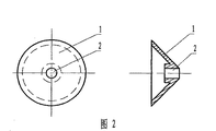
図1、半球型(放物面の形にしてもいい)風力推進碗1の正視図と左断面図;図2 円錐型(他の錘状にしてもいい)風力推進碗1の正視図と左断面図;図3、4、絶縁輪3を風力推進碗の穴2に通した時の局部の断面図、風力推進碗1と絶縁輪3を接着して、一緒に固定してある。図5、いくつかの、同一方向に並べてある風力推進碗1を絶縁輪3に通してある風力清掃輪の構成の見取り図である。図6、碍子4の構成の見取り図である。図7、風力清掃輪を碍子につける構成の見取り図である。風を受けると、風力清掃輪がまわる。そうすると、風力推進碗によって、碍子表面の汚れが擦り落とされる。それによって、碍子の表面は、清潔さを保たれて、汚れによる閃絡事故をふせぐことができる。
【0007】
風力清掃輪は、絶縁材料、例えば、プラスチックやゴムやナイロンなどによって作られる。風力清掃輪は、電力系統のどんな設備の磁器碍子のふちにつけてもかまわない。
【0008】
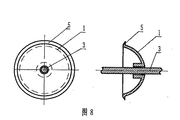
図8、9は、例2を実行する構成の見取り図である。例2と例1の区別は、風力推進碗の碗の縁に、汚れを取るスクレーパーがついているから、清掃が容易になることである。
図10、11、12は、例3を実行する構成の見取り図である。図面に描いてあるように、絶縁輪3の風力推進碗1の間に若干の、穴があいた隔離球6がある。それによって、風力推進碗1の間の距離を固定することができる。隔離球6の形は球状でも、管状でもいい。
【0009】
図12、管状の隔離球6を絶縁輪3にとおしてある風力清掃輪の局部の断面図である。
図13は、例4を実行する構成の見取り図である。図面に描いてあるように、絶縁輪3に凸型輪7がついている。それによって風力推進碗1を固定することができる。
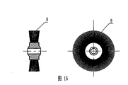
図14、15は、例5を実行する構成の見取り図である。清掃のスピードと効果を高めるため、絶縁輪3にはけ輪8を通してある。図15、はけ輪8の正視図と左からの図である。
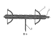
図16、17は、例6を実行する構成の見取り図である。絶縁体の縁も清掃できるようにするため 絶縁輪3にスクレーパー9をとおしてある。
図17、スクレーパー9の正視図と左からの図である。
【0010】
図18、19は、例7を実行する構成の見取り図である。製造する時、風力推進碗1と絶縁輪3は、固定されていっしょになり、一体の仕掛けになる。
図20、21は、例8を実行する構成の見取り図である。図面に描かれているようにすべでの風力清掃輪はジョイントを備える。ジョイントを構成するインタフェース10は、溶接でつなぐ;図21に描いてあるように、インタフェース10に一つのコネクティングフリーブでつなぐ、もしくは溶接する。
図22は、例9を実行する構成の図である。上述の風力清掃輪との違いは風力推進碗1を、絶縁輪3に通してあるのではなく、絶縁輪3の側に固定されていることである。
【0011】
工業上での応用:
本考案は、電力系統で幅広く用いる事ができ、碍子表面の汚れを清掃することによって、電力系統をさらに安全に運行することができる。本考案は、現在の技術と比べて、次の長所がある。(1) 碍子表面の汚れが、随時清掃できるから、その表面によごれがつくことがないこと。(2)大量の人力や物資が節約できる。(3)清掃に伴う不安な要素が取り除けること。
【図面の簡単な説明】
【0012】
【図1】半球型の風力推進碗の正視図(正面図)1Aと左断面図1Bである。
【図2】円錐体型の風力推進碗の正視図(正面図)2Aと左断面図2Bである。
【図3】絶縁輪に通した風力推進碗の局部の正視図(正面図)3Aと左断面図3Bである。
【図4】絶縁輪に通した風力推進碗の局部の正視図(正面図)4Aと左断面図4Bである。
【図5】風力清掃輪の構成の見取り図である。
【図6】碍子の見取り図である。
【図7】風力清掃輪をつけている碍子の見取り図である。
【図8】汚れをこすり落とす風力推進碗の構成の見取り図8A、8Bである。
【図9】汚れをこすり落とす風力推進碗の構成の見取り図9A、9Bである。
【図10】球状の隔離球(隔離の作用をはっきする球状のもの。)を絶縁輪に通してある風力清掃輪の構成の見取り図である。
【図11】球状の隔離球(隔離の作用をはっきする球状のもの。)を絶縁輪に通してある風力清掃輪の構成の見取り図である。
【図12】管状の隔離球を絶縁輪に通してある風力清掃輪の局部の断面図である。
【図13】凸型輪が付いている絶縁輪の風力清掃輪の局部の断面図である。
【図14】はけ輪を絶縁輪に通してある風力清掃輪の局部の断面図である。
【図15】はけ輪の正断面図15Aと左から見た図15Bである。
【図16】スクレーパーを絶縁輪に通してある風力清掃輪の局部の断面図である。
【図17】スクレーパーの正視図(正面図)17Aと左から見た図17Bである。
【図18】一体となった風力清掃輪の局部の断面図18A、18Bである。
【図19】一体となった風力清掃輪の局部の断面図19A、19Bである。
【図20】風力清掃輪のジョイントの局部の断面図である。
【図21】風力清掃輪のジョイントの局部の断面図である。
【図22】例9を実施する構成の見取り図である。
【符号の説明】
【0013】
1 風力推進碗
2 風力推進碗の穴
3 絶縁輪
4 碍子
5 汚れスクレーパー
6 隔離球
7 凸型輪
8 はけ輪
9 スクレーパー
10 インタフェース
11 コネクティングスリーブ【Technical field】
[0001]
The present invention relates to a device for cleaning a dirt on a surface of an insulator in a power system.
[Background Art]
[0002]
At present, the surface of the insulator used in the electric power system is very dirty and needs to be cleaned at regular intervals. The usual cleaning method is to wash off with human power, machine or water. It takes time and power to clean with manpower or machine. Water costs money. In some cases, geographical conditions make it impossible to use machinery or water. In short, no matter which of the above methods is used, a flash accident due to dirt frequently occurs unless dirt on the surface of the insulator is immediately cleaned.
[Disclosure of Invention]
[Problems to be solved by the invention]
[0003]
An object of the present invention is to provide a device called an “insulator wind cleaning wheel” that automatically cleans the surface of an insulator by borrowing wind power, overcoming the deficiencies of the current technology in view of the above circumstances. That is.
[Means for Solving the Problems]
[0004]
To achieve this purpose, the present inventors adopted the following technology. Several wind propulsion bowls (similar to a bowl-shaped bowl that rotate when exposed to wind) arranged in the same direction are passed through an insulating ring to form a wind cleaning wheel, which is then used as an insulator. When wind is applied, the wind swab rotates. Then, the dirt on the surface of the insulator is scraped off one after another by the wind propulsion bowl, and the surface of the insulator is kept clean, and a flash accident due to dirt can be prevented.
[Effect of the invention]
[0005]
The present invention has the following advantages as compared with the prior art.
1. Since the surface of the insulator can be cleaned at any time, the surface does not become dirty.
2. Large amounts of manpower and supplies can be saved.
3. Remove uneasy (unsafe) elements associated with cleaning.
[Best mode for carrying out the invention]
[0006]
A method for specifically executing the present invention will be described below.
1 to 7 are sketch drawings of a configuration for executing the first example.
Fig. 1, front view and left sectional view of a hemispherical (parabolic) wind propulsion bowl 1; Fig. 2 front view of a conical (other pyramidal) wind propulsion bowl 1 Left sectional view; FIGS. 3 and 4, sectional view of a local portion when insulating ring 3 is passed through hole 2 of wind propulsion bowl, wind propulsion bowl 1 and insulating ring 3 are adhered and fixed together. FIG. 5 is a sketch of a configuration of a wind cleaning wheel in which several wind propulsion bowls 1 arranged in the same direction are passed through an insulating wheel 3. FIG. 6 is a sketch of the configuration of the insulator 4. FIG. 7 is a sketch of a configuration in which a wind cleaning wheel is attached to an insulator. When the wind blows, the wind swab rotates. Then, the dirt on the insulator surface is scraped off by the wind propulsion bowl. Thereby, the surface of the insulator is kept clean, and it is possible to prevent a flash accident due to dirt.
[0007]
The wind cleaning wheel is made of an insulating material, for example, plastic, rubber, nylon, or the like. The wind swab can be attached to the edge of the porcelain insulator of any equipment in the power system.
[0008]
8 and 9 are sketch drawings of the configuration for executing the second example. The distinction between Example 2 and Example 1 is that the edge of the bowl of the wind propulsion bowl is provided with a scraper for removing dirt, thereby facilitating cleaning.
10, 11, and 12 are sketch drawings of the configuration for executing the third example. As depicted in the drawing, there are some perforated isolating spheres 6 between the wind propulsion bowls 1 of the insulating wheel 3. Thereby, the distance between the wind propulsion bowls 1 can be fixed. The shape of the isolation sphere 6 may be spherical or tubular.
[0009]
FIG. 12 is a sectional view of a local portion of the wind cleaning wheel in which the tubular isolation ball 6 is passed through the insulating wheel 3.
FIG. 13 is a sketch of a configuration for executing Example 4. As shown in the drawing, the insulating ring 3 is provided with a convex ring 7. Thereby, the wind propulsion bowl 1 can be fixed.
14 and 15 are sketch drawings of a configuration for executing the fifth example. In order to increase the speed and effectiveness of cleaning, the insulating wheel 3 is provided with a flywheel 8. FIG. 15 is a front view of the flywheel 8 and a view from the left.
16 and 17 are sketch drawings of the configuration for executing the sixth example. A scraper 9 is passed through the insulating ring 3 so that the edge of the insulator can be cleaned.
FIG. 17 is a front view of the scraper 9 and a view from the left.
[0010]
18 and 19 are sketch drawings of the configuration for executing Example 7. At the time of manufacture, the wind propulsion bowl 1 and the insulating wheel 3 are fixed together and become an integral device.
20 and 21 are sketch drawings of the configuration for executing the eighth example. All wind sweep wheels have joints as depicted in the drawing. The interfaces 10 that make up the joints are connected by welding; as illustrated in FIG. 21, they are connected to the interface 10 by one connecting leaf or welded.
FIG. 22 is a diagram of a configuration for executing the ninth example. The difference from the above-mentioned wind cleaning wheel is that the wind propulsion bowl 1 is not passed through the insulating wheel 3 but is fixed to the insulating wheel 3 side.
[0011]
Industrial applications:
INDUSTRIAL APPLICABILITY The present invention can be widely used in a power system, and the power system can be operated more safely by cleaning dirt on the insulator surface. The present invention has the following advantages as compared with the current technology. (1) Dirt on the insulator surface can be cleaned at any time, so that the surface should not be soiled. (2) A large amount of manpower and supplies can be saved. (3) To be able to remove uneasy factors associated with cleaning.
[Brief description of the drawings]
[0012]
FIG. 1 is a front view (front view) 1A and a left sectional view 1B of a hemispherical wind propulsion bowl.
FIG. 2 is a front view (front view) 2A and a left sectional view 2B of a conical wind propulsion bowl.
FIG. 3 is a front view (front view) 3A and a left sectional view 3B of a local portion of the wind propulsion bowl passed through an insulating wheel.
FIG. 4 is a front view (front view) 4A and a left sectional view 4B of a local portion of the wind propulsion bowl passed through the insulating wheel.
FIG. 5 is a sketch of a configuration of a wind cleaning wheel.
FIG. 6 is a sketch of an insulator.
FIG. 7 is a sketch of an insulator with a wind cleaning wheel.
FIGS. 8A and 8B are sketches 8A and 8B of a configuration of a wind propulsion bowl for rubbing off dirt.
FIGS. 9A and 9B are sketches 9A and 9B of a configuration of a wind propulsion bowl for rubbing off dirt.
FIG. 10 is a schematic view of a configuration of a wind cleaning wheel in which a spherical isolating sphere (a spherical sphere that separates the action of isolation) is passed through an insulating wheel.
FIG. 11 is a schematic view of a configuration of a wind cleaning wheel in which a spherical isolating sphere (a spherical sphere that separates the action of isolation) is passed through an insulating wheel.
FIG. 12 is a cross-sectional view of a local portion of a wind cleaning wheel having a tubular isolating ball passed through an insulating wheel.
FIG. 13 is a cross-sectional view of a local portion of a wind-cleaning wheel of an insulating wheel having a convex wheel.
FIG. 14 is a cross-sectional view of a local portion of a wind cleaning wheel having a brush wheel passed through an insulating wheel.
FIG. 15 is a front sectional view 15A of the flywheel and FIG. 15B viewed from the left.
FIG. 16 is a cross-sectional view of a local portion of a wind cleaning wheel in which a scraper is passed through an insulating wheel.
17 is a front view (front view) 17A of the scraper and FIG. 17B viewed from the left.
FIG. 18 is a sectional view 18A, 18B of a local portion of the integrated wind cleaning wheel.
FIGS. 19A and 19B are sectional views 19A and 19B of a local portion of the integrated wind cleaning wheel.
FIG. 20 is a sectional view of a local portion of a joint of the wind cleaning wheel.
FIG. 21 is a sectional view of a local portion of a joint of the wind cleaning wheel.
FIG. 22 is a sketch of a configuration for implementing Example 9;
[Explanation of symbols]
[0013]
DESCRIPTION OF SYMBOLS 1 Wind-powered propulsion bowl 2 Hole of wind-powered propulsion bowl 3 Insulating wheel 4 Insulator 5 Dirt scraper 6 Separation ball 7 Convex ring 8 Brush wheel 9 Scraper 10 Interface 11 Connecting sleeve