【0001】
【考案の属する技術分野】
本考案は、椅子構造に係わり、特に使用時には穏やかに展開保持する特性を有しつつ、不使用時には気軽に折畳み収納できる特性を有し、平時に座りパッドを支持横棒に対し架設する場合に、その間における対応する段落に配置される柔軟性を有する突き上げ部材と弾性的な接触を形成でき、使用上に快適さを向上できる椅子構造に関するものである。
【0002】
【従来技術】
業界では、人間の座ることに供する、それぞれ異なる使途を有する椅子構造について開発がなされており、その組立設計はすべて使用場所と使用用途に向けて改善が実施されるので、マーケットにおいて販売されるそれぞれ異なる機能を有する椅子構造や、関連の週刊誌に刊行されるそれぞれの性質を有する椅子構造や、雑誌や国内外公開の特許誌に公開されるそれぞれのタイプの椅子構造などから見て、目前では、これらの多様化の組立機能を有する椅子製品はそれぞれの消費レベルに応じて使用者の好みに対応した選択を提供している。
【0003】
【考案の目的】
本考案は、前記に掲げた同一の性質を有する、気軽に折畳み収納でき、且つ展開架設できる、椅子組立構造を新たな構成によって表現を醸し出し、一般の使用者は使用時に座りパッドを支持横棒に対して架設をすることによって支持横棒において一つ以上の柔軟性を有する突き上げ部材によって保持をし、座りパッドの底部と弾性的な接触をし、人間の臀部が座り込むと、快適さを醸し出せ、且つ前記支持横棒の両側に掛けられる連結ユニットより外方へフランジ部が延出形成され、座りパッドの左右側がそれぞれ対応する二つの連結ユニットと結合をすると、上向いて曲がって折畳み収納し、または前向いて引き上がって水平に架設できるので、すべて連結ユニットの外周縁部に延出されるフランジ部と、隣り合う支持脚架とで仕切り構造を形成でき、座りパッドが内外方へ作動される場合に両側の脚架にタッチしないような実施を実現できる。
【0004】
本考案は、座り位置の両側にそれぞれ支持脚架を配設し、且つ左右支持脚架の予め決めた高さに支持横棒を架橋し、且つ連結ユニットを介して座りパッドを活動可能にそれらの部材の間に架設するようにした椅子構造において、左右支持脚架の間における支持横棒の中間段落において予め前向きに傾斜する角度を設定しておかれる座りパッド載置段が凹んで形成されており、当該座りパッド載置段には一つ以上の前向いて延伸される支持部材同士が固着され、それらの支持部材の上端部における孔部に柔軟性を有する突き上げ部材が位置決め結合され、支持横棒の間に架設される座りパッドの底部と弾性的に接触し合い、人間の臀部の座り込みに供することができ、他に、前記支持横棒の両側に組立てられる連結ユニットにおいて外方へ延出するフランジ部を有し、座りパッドの左右側が対応する連結ユニットと結合する用途に供し、上向いて曲がって折畳み収納に供し、または前向いて回転させて水平架設に供し、連結ユニットより外方へ延出するフランジ部と隣り合う支持脚架とで仕切り手段を形成でき、座りパッドが内外へ作動される場合に両側の脚架に接触させない機能を提供できることを特徴とする、椅子構造を提供することをその主要的な目的とする。
【0005】
以下に添付図面を参照しながら本考案の好適な実施の形態を詳細的で具体的に説明する。
【0006】
【考案の実施の形態】
本考案の設計による椅子構造は、図1に示すように、主に、活動可能に折畳み収納可能な形式の左右支持脚架(1)と、それらの左右支持脚架(1)同士の予め設定される高さに架設される支持横棒(2)と、前記支持横棒(2)の間に固着される一つ以上の支持部材(3)と、座りパッド(6)と支持横棒(2)とを結合する連結ユニット(5)とからなる。そのうち、前記左右支持脚架(1)の予め設定される高さに架設される支持横棒(2)の中間段落において、予め設定される前向きに傾斜する角度に沿って架設される座りパッド載置段(21)が凹んで形成されており(ここで、載置段(21)の凹み深さは座りパッド(6)の中間段落における下向いて凹む形態によって該当する架設許容空間を決める)、座りパッド載置段(21)の間で一つ以上の前向きに延伸し出す支持部材(3)が設けてあり、当該支持部材(3)の上端部の板体(31)に形成される孔部(32)に、該当する外径の柔軟性を有する突き上げ部材(4)によって位置決め結合され、また、支持横部(2)の両側の高いほうの段落に二ペアの半分形態の連結部材(51,52)が設けられ、相互に密接的により合わせられており、且つ複数の螺着部材(54)によって二つの連結部材(51,52)で連結ユニット(5)を形成するように結合し、活動的に前記支持横棒(2)の左右に連結される連結部材(51,52)より外方へフランジ部(53)が延出形成しており、組立できあがった両側の連結ユニット(5)と、左右支持脚架(1)に隣り合う箇所で仕切りエリアを形成させ(図3参照)、支持横棒(20)の両側に組立てられる連結ユニット(5)の上側のレベルと座りパッド(6)の底側の対応しあう部位において単に数個の螺着部材(54)によって一体になるように結合が実施される(図2参照)。
【0007】
組立できあがった椅子(7)は、平時に一般の使用者の利用に供する場合に(図4参照)、座りパッド(6)を支持横棒(2)に対し水平に架設されることを実施でき、それらの間の支持部材(3)に結合される柔軟性を有する突き上げ部材(4)は、臀部が座り込む場合に水平に架設される状態を保持できるが、同時に快適な弾性的接触を提供でき、人間が座り込む際に快適な座り品質を提供できるようになる。
【0008】
また、椅子(7)を上向いて曲がって折畳み収納する場合に複数個の椅子(7)を積み重ねることができ(図5と図6参照)、または、それを前向いて押し付けて水平に支持横棒(2)に架設する場合に(図2参照)、支持横棒(2)の両側に組立てられる連結ユニット(5)の後向いて延出されるフランジ部(53)を、それらと隣り合う支持脚架(1)とで仕切りエリアを形成でき(図3参照)、支持横棒(2)における座りパッド(6)が内外方へ作動される場合に、左右支持脚架(1)と相互に干渉を生じないように設定することができる。
【図面の簡単な説明】
【図1】本考案の椅子構造を示す分解斜視図である。
【図2】本考案の椅子構造を示す一部断面側面図である。
【図3】本考案の椅子構造を示す前面図である。
【図4】本考案の椅子に臀部が座り込む後の座りパッドと突き上げ部材との弾性的な突き上げ接触状態を示す説明図である。
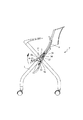
【図5】本考案による椅子構造を折畳み収納する場合の状態を示す説明図である。
【図6】複数個の本考案による椅子同士を積み重ねて収納する場合を示す説明図である。
【符号の説明】
1 脚架
2 支持横棒
21 載置段
3 支持部材
31 板体
32 孔部
4 突き上げ部材
5 連結ユニット
51,52 連結部材
53 フランジ部
54 螺着部材
6 座りパッド
7 椅子[0001]
[Technical field to which the invention belongs]
The present invention relates to a chair structure, in particular, has a characteristic of gently expanding and holding when used, and has a characteristic that it can be easily folded and stored when not in use. The present invention relates to a chair structure capable of forming an elastic contact with a flexible push-up member arranged in a corresponding paragraph therebetween, thereby improving comfort in use.
[0002]
[Prior art]
In the industry, chair structures with different uses for human sitting have been developed, and all of their assembly designs have been improved for the place and use, so each one sold in the market In view of the chair structure with different functions, the chair structure with each characteristic published in the related weekly magazine, and the chair structure of each type published in magazines and patent publications published in Japan and overseas, Chair products with these diversified assembling functions provide a selection corresponding to the user's preference according to their consumption level.
[0003]
[Purpose of the invention]
The present invention expresses a new structure of a chair assembly structure having the same properties as described above, which can be easily folded and stored, and can be deployed and erected, and a general user supports the sitting pad when using the seat pad. Erection of the support bar by means of one or more flexible push-up members, making elastic contact with the bottom of the sitting pad, providing comfort when the human buttocks sit down. The flange portion is formed to extend outward from the connecting unit that can be put out and hanged on both sides of the support horizontal bar. Or, it can be pulled up to the front and can be installed horizontally. Formation can be realized an implementation that does not touch the sides of the sea lions when sitting pad is actuated in and out direction.
[0004]
The present invention provides support legs on both sides of the sitting position, bridges the supporting horizontal bar to a predetermined height of the left and right supporting legs, and activates the sitting pad via the connecting unit. In the chair structure that is constructed between the members of the above, in the middle paragraph of the support horizontal bar between the left and right support legs, the sitting pad mounting step that is set in advance at an angle to incline forward is formed in a concave shape. At least one support member extending forward is fixed to the sitting pad mounting stage, and a flexible push-up member is positioned and coupled to a hole at an upper end portion of the support member, It can elastically contact with the bottom of the seat pad erected between the support bars and can be used to sit down on the buttocks of a human, and in addition, outwardly in the connecting unit assembled on both sides of the support bar. Extension For use in which the left and right sides of the seat pad are connected to the corresponding connection unit, bend upward and use for folding storage, or rotate forward and use for horizontal erection, outward from the connection unit. A chair structure, characterized in that a partitioning means can be formed by an extending flange portion and an adjacent support leg, and a function can be provided that does not contact the legs on both sides when the seat pad is actuated in and out. That is its primary purpose.
[0005]
Hereinafter, preferred embodiments of the present invention will be described in detail with reference to the accompanying drawings.
[0006]
[Embodiment of the invention]
As shown in FIG. 1, the chair structure according to the design of the present invention mainly includes left and right support legs (1) of a type that can be folded and stored operatively, and presets of the left and right support legs (1). Support bar (2) erected at a predetermined height, one or more support members (3) fixed between the support bar (2), a seat pad (6) and a support bar ( 2) and a connecting unit (5) for connecting the above. In the middle section of the support bar (2) installed at a preset height of the left and right support legs (1), a seat pad mounting is installed along a preset forwardly inclined angle. The mounting stage (21) is formed in a concave shape (where the depth of the concave portion of the mounting stage (21) is determined according to the downwardly concave shape in the middle paragraph of the sitting pad (6)). One or more forwardly extending support members (3) are provided between the sitting pad placement steps (21), and are formed on the plate (31) at the upper end of the support members (3). The hole (32) is positioned and connected by a flexible push-up member (4) of an appropriate outer diameter, and two pairs of half-shaped connecting members are provided in the higher paragraphs on both sides of the supporting lateral portion (2). (51, 52) are provided, and And two connecting members (51, 52) are connected by a plurality of screwing members (54) to form a connecting unit (5), and are actively connected to the left and right sides of the support cross bar (2). Flanges (53) extend outwardly from the connecting members (51, 52) to be connected, and are located adjacent to the connecting units (5) on both sides that have been assembled and the left and right support legs (1). To form a partition area (see FIG. 3), and only a few at the corresponding level on the upper level of the connecting unit (5) assembled on both sides of the support crossbar (20) and the bottom side of the seat pad (6). (See FIG. 2).
[0007]
The chair (7) that has been assembled can be constructed such that the sitting pad (6) is installed horizontally with respect to the supporting horizontal bar (2) when the chair (7) is to be used by ordinary users during normal times (see FIG. 4). The flexible push-up member (4) coupled to the support member (3) between them can maintain a horizontally erected state when the buttocks are seated, but at the same time provide a comfortable elastic contact. Therefore, it is possible to provide comfortable sitting quality when a person sits down.
[0008]
Further, when the chair (7) is bent upward and folded and stored, a plurality of chairs (7) can be stacked (see FIGS. 5 and 6), or they can be pressed forward and horizontally supported horizontally. When it is installed on the rod (2) (see FIG. 2), the rearwardly extending flange portion (53) of the connecting unit (5) assembled on both sides of the supporting horizontal bar (2) is supported by the supporting member adjacent thereto. A partition area can be formed with the pedestal (1) (see FIG. 3), and when the seat pad (6) on the support bar (2) is actuated inward and outward, the left and right support pedestals (1) are mutually connected. It can be set so as not to cause interference.
[Brief description of the drawings]
FIG. 1 is an exploded perspective view showing a chair structure of the present invention.
FIG. 2 is a partially sectional side view showing the chair structure of the present invention.
FIG. 3 is a front view showing the chair structure of the present invention.
FIG. 4 is an explanatory view showing a state in which the sitting pad and the push-up member are elastically pushed up after the buttocks are seated in the chair of the present invention.
FIG. 5 is an explanatory view showing a state where the chair structure according to the present invention is folded and stored.
FIG. 6 is an explanatory view showing a case where a plurality of chairs according to the present invention are stacked and stored.
[Explanation of symbols]
REFERENCE SIGNS LIST 1 leg 2 supporting horizontal bar 21 mounting step 3 supporting member 31 plate 32 hole 4 push-up member 5 connecting unit 51, 52 connecting member 53 flange 54 screwing member 6 sitting pad 7 chair