JP3097251U - Fluorescent lamp fall prevention device - Google Patents
Fluorescent lamp fall prevention device Download PDFInfo
- Publication number
- JP3097251U JP3097251U JP2003002126U JP2003002126U JP3097251U JP 3097251 U JP3097251 U JP 3097251U JP 2003002126 U JP2003002126 U JP 2003002126U JP 2003002126 U JP2003002126 U JP 2003002126U JP 3097251 U JP3097251 U JP 3097251U
- Authority
- JP
- Japan
- Prior art keywords
- fluorescent lamp
- prevention device
- bent
- fall prevention
- reflector
- Prior art date
- Legal status (The legal status is an assumption and is not a legal conclusion. Google has not performed a legal analysis and makes no representation as to the accuracy of the status listed.)
- Expired - Lifetime
Links
Images


Landscapes
- Securing Globes, Refractors, Reflectors Or The Like (AREA)
- Fastening Of Light Sources Or Lamp Holders (AREA)
Abstract
【課題】蛍光灯具の蛍光灯を所定の取り付け位置に確実に保持することができ、蛍光灯の取り付けも容易に行えるようにした新規な構造の脱落防止具を得る。
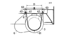
【解決手段】帯状板材を略U字乃至V字形に屈曲させ、その一端部に被回転支持部62、他端部に外方折り返し部63を設けて形成し、被回転支持部62を反射板4で回転自在に支持し、外方折り返し部63を反射板4に設けた被係合部42に着脱自在とし、蛍光灯5の下部周面を屈曲部61で支持する。
【選択図】 図3An object of the present invention is to provide a fluorescent lamp having a novel structure in which a fluorescent lamp can be securely held at a predetermined mounting position and a fluorescent lamp can be easily mounted.
A belt-shaped plate is bent into a substantially U-shaped or V-shaped form, and a rotatable support portion is provided at one end thereof and an outwardly folded portion 63 is provided at the other end thereof. 4, the outer folded portion 63 is detachably attached to the engaged portion 42 provided on the reflection plate 4, and the lower peripheral surface of the fluorescent lamp 5 is supported by the bent portion 61.
[Selection diagram] FIG.
Description
【0001】
【考案の属する技術分野】
本考案は、蛍光灯具の蛍光灯が適正な取り付け位置から脱落するのを防止するための器具に関する。
【0002】
【従来の技術】
駅のプラットホームなどに設置される、2mほどの長い蛍光灯を装備した蛍光灯具には、蛍光灯の落下を防止する脱落防止具が取り付けられている。
この脱落防止具10は、図5に示されるように、蛍光灯12の外径と略同じ幅に設けた基部10aの両端部から腕部10b、10bを平行に突出させるともに両腕部の先端を互いに先細り状に湾曲させて形成されており、蛍光灯具11の反射板13に基部10aをネジ止め固定し、反射板13から垂下した腕部10b、10bの間に、端部を電極ソケット14に嵌め入れた蛍光灯12を圧入し、両腕部で蛍光灯12の外周を挟み持って支持するようになっていた。
【0003】
【考案が解決しようとする課題】
従来の脱落防止具10は、反射板13の下面に固定されていたため、蛍光灯12を取り付ける際に、蛍光灯12の両端電極を電極ソケット14に嵌め込む操作と蛍光灯12を脱落防止具10に差し入れる操作を同時に行わなければならず、取り付け操作が煩わしく手間がかかるという問題があった。
【0004】
本考案は従来の技術の有するこのような問題点に鑑み、蛍光灯具の蛍光灯を所定の取り付け位置に確実に保持することができ、また、蛍光灯の取り付けも容易に行えるようにした新規な構造の脱落防止具を得ることを課題とする。
【0005】
【課題を解決するための手段】
前記課題を解決するため本考案の蛍光灯の脱落防止具は、帯状板材を略U字乃至V字形に屈曲させてなり、その両端部を蛍光灯具の反射板に取り付け、反射板から吊り下がった屈曲部側で蛍光灯の下部外周を支持するように構成されたことを特徴とする。
【0006】
前記構成の脱落防止具において、一端部に被回転支持部、他端部に外方折り返し部を設けて形成し、前記被回転支持部が反射板に回転自在に支持され、前記外方折り返し部が反射板に設けた被係合部に着脱自在とされるように設けることが好ましい。
【0007】
これによれば、反射板から吊り下がった脱落防止具の屈曲部が蛍光灯の下側をぐるりと包囲して蛍光灯下面を支持し、蛍光灯を所定の取り付け位置に固定し保持させることができる。
また、反射板に対し、脱落防止具の一端部が回動自在、他端部が着脱自在に設けてあれば、反射板の下側で脱落防止具を回動させて変位させることができるので、電極ソケットに蛍光灯を取り付ける際に脱落防止具が邪魔となるようなこはなく、蛍光灯の取り付け操作をスムーズに行える。
【0008】
【考案の実施の形態】
図1は本考案の一実施形態の脱落防止具を装備した蛍光灯具の外観を示している。図示されるように、この蛍光灯具1は、下部を開口面とした枠体2と、枠体2内に取り付けられる電極ソケット3及び反射板4と、電極ソケット3、3間に支持される蛍光灯5との各部材により構成されており、蛍光灯5の周面二箇所に脱落防止具6を装着して蛍光灯5が支持されるようになっている。
【0009】
詳しくは、図2に示されるように、脱落防止具6は、細長いステンレス板などの帯状板材を略V字形に折り曲げてなり、その中央部を蛍光灯5の外径と略同径に屈曲させ、その一端部62を筒状に折り曲げ、他端部63を外側に折り返した形状に形成されている。
【0010】
そして、図3に示されるように、脱落防止具6は、その筒状端部62が反射板4に形成された孔部41に係入され、同孔部内に架設した回転軸43を挿通させて反射板4に回転自在に取り付けられ、また、折り返し端部63が、同じく反射板4に形成された孔部42内に係合自在に設けてあり、折り返し端部63を孔部42に係合させた状態では屈曲部61が反射板4の下側に吊り下がり、電極ソケット3、3間に取り付けた蛍光灯5の下部周面を屈曲部61で支持するようになっている。
【0011】
なお、反射板4の孔部41、42間の幅Dは、脱落防止具6の両端部間の幅dよりも僅かに狭く設定してあり、折り返し端部63を孔部42に係合させたときに、脱落防止具自体の弾性によって折り返し端部63を孔部42の縁部に押圧することにより係合状態が維持されるようになっている。
【0012】
脱落防止具6が装備された蛍光灯具1に蛍光灯5を取り付ける操作は、先ず、折り返し端部63を反射板4から取り外して脱落防止具6を宙ぶらりんとし、その状態で蛍光灯5の両端電極を電極ソケット3、3に嵌め入れ、次いで、脱落防止具6を蛍光灯5の外周に掛け回し、折り返し端部63を孔部42に係合させて完了する。
このように、蛍光灯5を取り付ける際に脱落防止具6が邪魔とならず、蛍光灯5を電極ソケット3、3に取り付けた後で脱落防止具6を装着すればよいので、従来のものと比較して蛍光灯5の取り付け操作が簡単になり、迅速且つスムーズな取り付けを可能とし、また、蛍光灯5の下部周面に掛け回した脱落防止具6の屈曲部61で蛍光灯5を安定的に支持することができる
【0013】
なお、図示した脱落防止具6の形態は一例であり、本考案は他の様々な形態で構成することができる。脱落防止具6は、反射板4から吊り下がった屈曲部61で蛍光灯5の下部を支持可能であれば屈曲形状は問わず、他の適宜な形態に設けることができる。図4は他の形態例を示し、同図(A)は屈曲部61が折れ曲がったもの、同図(B)、(C)は全体が略U字形の屈曲したもの、同図(D)は屈曲部61内に折れ部を設けたものである。また、脱落防止具6の両端部62、63を、反射板5に対して着脱自在としてもよい。
【図面の簡単な説明】
【図1】本考案の一実施形態の脱落防止具を装着した蛍光灯具の外観図である。
【図2】図1の脱落防止具の正面図と側面図である。
【図3】図1の脱落防止具で蛍光灯を支持する状態を示した図である。
【図4】脱落防止具の他の形態を示した図である。
【図5】従来の蛍光灯具の要部破断拡大側面図(A)と、正面端部部分を拡大断面で示した図(B)である。
【符号の説明】
1 蛍光灯具、2 枠体、3 電極ソケット、4 反射板、5 蛍光灯、6 脱落防止具、61 屈曲部、62 筒状端部、63 折り返し端部[0001]
[Technical field to which the invention belongs]
The present invention relates to a device for preventing a fluorescent lamp of a fluorescent lamp from falling off from a proper mounting position.
[0002]
[Prior art]
Fluorescent lamps installed on a platform of a station or the like and equipped with fluorescent lamps as long as about 2 m are provided with fall-off prevention devices for preventing the fluorescent lamps from falling.
As shown in FIG. 5, the drop-
[0003]
[Problems to be solved by the invention]
Since the conventional
[0004]
The present invention has been made in view of the above-mentioned problems of the prior art, and is a new type of fluorescent lamp that can securely hold a fluorescent lamp of a fluorescent lamp at a predetermined mounting position, and that can be easily mounted. An object of the present invention is to obtain a structure fall prevention device.
[0005]
[Means for Solving the Problems]
In order to solve the above problems, the fluorescent lamp fall prevention device of the present invention is formed by bending a band-shaped plate material into a substantially U-shaped or V-shaped shape, and both ends thereof are attached to the reflector of the fluorescent lamp and suspended from the reflector. The bent portion side is configured to support the lower periphery of the fluorescent lamp.
[0006]
In the fall-off preventing device having the above-described configuration, the one end portion is provided with a rotatably supported portion, and the other end portion is provided with an outwardly folded portion. Is preferably provided so as to be detachable from an engaged portion provided on the reflection plate.
[0007]
According to this, the bent portion of the fall-off prevention device hung from the reflection plate surrounds the lower side of the fluorescent lamp and supports the fluorescent lamp lower surface, thereby fixing and holding the fluorescent lamp at a predetermined mounting position. it can.
In addition, if one end of the stopper is rotatably provided and the other end is detachably provided with respect to the reflector, the stopper can be rotated and displaced below the reflector. In addition, when the fluorescent lamp is attached to the electrode socket, the fall-off preventing device does not hinder the operation, and the attaching operation of the fluorescent lamp can be performed smoothly.
[0008]
[Embodiment of the invention]
FIG. 1 shows the appearance of a fluorescent lamp equipped with a fall prevention device according to an embodiment of the present invention. As shown in the figure, the fluorescent lamp 1 includes a frame 2 having a lower portion as an opening surface, an
[0009]
More specifically, as shown in FIG. 2, the fall-
[0010]
As shown in FIG. 3, the
[0011]
Note that the width D between the
[0012]
The operation of attaching the
As described above, when the
It should be noted that the illustrated form of the
[Brief description of the drawings]
FIG. 1 is an external view of a fluorescent lamp equipped with a fall prevention device according to an embodiment of the present invention.
2A and 2B are a front view and a side view of the fall prevention device of FIG.
FIG. 3 is a view showing a state in which a fluorescent lamp is supported by the drop-off preventing device of FIG. 1;
FIG. 4 is a view showing another embodiment of the drop-off preventing device.
FIG. 5 is an enlarged side view (A) of a main part of a conventional fluorescent lamp, in which the front end portion is shown in an enlarged cross section.
[Explanation of symbols]
DESCRIPTION OF SYMBOLS 1 Fluorescent light fixture, 2 frame bodies, 3 electrode sockets, 4 reflectors, 5 fluorescent lamps, 6 drop-off prevention tools, 61 bent portions, 62 cylindrical end portions, 63 folded end portions
Claims (2)
Priority Applications (1)
| Application Number | Priority Date | Filing Date | Title |
|---|---|---|---|
| JP2003002126U JP3097251U (en) | 2003-04-17 | 2003-04-17 | Fluorescent lamp fall prevention device |
Applications Claiming Priority (1)
| Application Number | Priority Date | Filing Date | Title |
|---|---|---|---|
| JP2003002126U JP3097251U (en) | 2003-04-17 | 2003-04-17 | Fluorescent lamp fall prevention device |
Publications (1)
| Publication Number | Publication Date |
|---|---|
| JP3097251U true JP3097251U (en) | 2004-01-22 |
Family
ID=43251069
Family Applications (1)
| Application Number | Title | Priority Date | Filing Date |
|---|---|---|---|
| JP2003002126U Expired - Lifetime JP3097251U (en) | 2003-04-17 | 2003-04-17 | Fluorescent lamp fall prevention device |
Country Status (1)
| Country | Link |
|---|---|
| JP (1) | JP3097251U (en) |
Cited By (4)
| Publication number | Priority date | Publication date | Assignee | Title |
|---|---|---|---|---|
| JP3166927U (en) * | 2010-12-16 | 2011-03-31 | アイリスオーヤマ株式会社 | Fall prevention device |
| JP2011165340A (en) * | 2010-02-04 | 2011-08-25 | Yamaguchi Engineering Kk | Lamp tool and manufacturing method of lamp tool |
| JP5232326B1 (en) * | 2012-11-19 | 2013-07-10 | 英資 森田 | Rivet, lighting desorption prevention tool, and lighting device |
| JP5349704B1 (en) * | 2013-03-21 | 2013-11-20 | 英資 森田 | Rivet, lighting desorption prevention tool, and lighting device |
-
2003
- 2003-04-17 JP JP2003002126U patent/JP3097251U/en not_active Expired - Lifetime
Cited By (4)
| Publication number | Priority date | Publication date | Assignee | Title |
|---|---|---|---|---|
| JP2011165340A (en) * | 2010-02-04 | 2011-08-25 | Yamaguchi Engineering Kk | Lamp tool and manufacturing method of lamp tool |
| JP3166927U (en) * | 2010-12-16 | 2011-03-31 | アイリスオーヤマ株式会社 | Fall prevention device |
| JP5232326B1 (en) * | 2012-11-19 | 2013-07-10 | 英資 森田 | Rivet, lighting desorption prevention tool, and lighting device |
| JP5349704B1 (en) * | 2013-03-21 | 2013-11-20 | 英資 森田 | Rivet, lighting desorption prevention tool, and lighting device |
Similar Documents
| Publication | Publication Date | Title |
|---|---|---|
| CA2804563C (en) | Downlight support | |
| JP3097251U (en) | Fluorescent lamp fall prevention device | |
| JP2009129772A (en) | Lamp, and lighting system | |
| US6824298B2 (en) | Lock-A-Lite mounting bracket | |
| AU2011100986A4 (en) | Downlight Fixture Mechanism | |
| US20090219725A1 (en) | Helicoidal System For Recessed Light Fixture Assembly | |
| JP3131836U (en) | lighting equipment | |
| RU2004122776A (en) | BUILT-IN CEILING DETAILS FOR BUILT-IN CEILING LUMINAIRES | |
| TWI518279B (en) | Lamps and their fixtures | |
| JP2007257879A (en) | Lighting apparatus | |
| JP4102271B2 (en) | External lighting system | |
| CN219120459U (en) | Lamp clamping device and lighting equipment | |
| JP4211047B2 (en) | lighting equipment | |
| JP7278912B2 (en) | Drop prevention device and lighting device for straight tube lamp | |
| JP2008004479A (en) | Illumination device | |
| JP4569771B2 (en) | lighting equipment | |
| US7296907B2 (en) | Lighting fixture | |
| JP2004342486A (en) | Mounting structure for attachment member to luminaire | |
| JP3148549U (en) | Mounting bracket | |
| JPH10255538A (en) | Discharge lamp luminaire and reflector mounting tool for the luminaire | |
| TWM455814U (en) | Lamp with fastening device | |
| JP2019057396A (en) | Lighting fixture | |
| JPH052910A (en) | Lighting fixture | |
| JPH0719047Y2 (en) | lighting equipment | |
| KR200351628Y1 (en) | Hood Lamp for Gas Range |
Legal Events
| Date | Code | Title | Description |
|---|---|---|---|
| R250 | Receipt of annual fees |
Free format text: JAPANESE INTERMEDIATE CODE: R250 |
|
| FPAY | Renewal fee payment (event date is renewal date of database) |
Free format text: PAYMENT UNTIL: 20080806 Year of fee payment: 5 |
|
| FPAY | Renewal fee payment (event date is renewal date of database) |
Free format text: PAYMENT UNTIL: 20090806 Year of fee payment: 6 |
|
| EXPY | Cancellation because of completion of term | ||
| FPAY | Renewal fee payment (event date is renewal date of database) |
Free format text: PAYMENT UNTIL: 20090806 Year of fee payment: 6 |