JP2025041262A - Flight system, control device, and method for controlling flying object - Google Patents

Flight system, control device, and method for controlling flying object Download PDF

Info

Publication number
JP2025041262A
JP2025041262A JP2023148453A JP2023148453A JP2025041262A JP 2025041262 A JP2025041262 A JP 2025041262A JP 2023148453 A JP2023148453 A JP 2023148453A JP 2023148453 A JP2023148453 A JP 2023148453A JP 2025041262 A JP2025041262 A JP 2025041262A
Authority
JP
Japan
Prior art keywords
flight
detection
aircraft
unit
range
Prior art date
Legal status (The legal status is an assumption and is not a legal conclusion. Google has not performed a legal analysis and makes no representation as to the accuracy of the status listed.)
Pending
Application number
JP2023148453A
Other languages
Japanese (ja)
Inventor
大輔 水野
Daisuke Mizuno
貴景 森本
Yoshihiro Morimoto
拓海 越本
Takumi Koshimoto
智香 山口
Chika Yamaguchi
Current Assignee (The listed assignees may be inaccurate. Google has not performed a legal analysis and makes no representation or warranty as to the accuracy of the list.)
Mitsubishi Electric Corp
Original Assignee
Mitsubishi Electric Corp
Priority date (The priority date is an assumption and is not a legal conclusion. Google has not performed a legal analysis and makes no representation as to the accuracy of the date listed.)
Filing date
Publication date
Application filed by Mitsubishi Electric Corp filed Critical Mitsubishi Electric Corp
Priority to JP2023148453A priority Critical patent/JP2025041262A/en
Publication of JP2025041262A publication Critical patent/JP2025041262A/en
Pending legal-status Critical Current

Links

Images

Landscapes

  • Control Of Position, Course, Altitude, Or Attitude Of Moving Bodies (AREA)
  • Traffic Control Systems (AREA)

Abstract

To provide a flight system, control device, and control method for a flying body, capable of appropriately detecting information that should be detected by the flying body.SOLUTION: A flight system includes: a flying body 1 that flies in the air; a flight information acquisition unit that acquires flight information on the flying body 1 including the flight position and attitude; a flight control unit that controls the flying body 1 on the basis of the flight information acquired by the flight information acquisition unit; and a detection unit that is mounted on the flying body 1, and detects target information from a detection target 4 during flight of the flying body 1. The detection target 4 includes a plurality of detection target regions 5, and the detection unit has a reference axis refA and detects the target information from the detection target regions 5 along the reference axis refA. When the detection unit detects the target information from the plurality of detection target regions 5, the flight control unit controls the flying body 1 such that an angle formed between the reference axis refA of the detection unit and a predetermined detection direction for each of the detection target regions 5 falls within a predetermined first range.SELECTED DRAWING: Figure 5

Description

本開示は、飛行体を制御する飛行システム、制御装置および飛行体の制御方法に関する。 This disclosure relates to a flight system for controlling an aircraft, a control device, and a method for controlling the aircraft.

近年、トンネル、橋梁などのインフラ構造物の点検に、無人飛行体の遠隔操作または自律飛行が活用されている。無人飛行体としてのドローンを自律飛行させる場合には、ドローンに開始位置、経由位置および目的位置(終点)などを表す経路情報を与えて、ドローンがGlоbal Pоsitiоning System(GPS)などの自己位置を推定する機能などを用いて飛行する。 In recent years, remote control or autonomous flight of unmanned aerial vehicles has been used to inspect infrastructure structures such as tunnels and bridges. When flying a drone as an unmanned aerial vehicle autonomously, the drone is given route information indicating the starting position, intermediate positions, and destination position (end point), and the drone flies using functions such as the Global Positioning System (GPS) to estimate its own position.

ドローンが自律飛行している際に、ドローンに搭載したセンサーにより検出された画像またはセンサー情報を、リアルタイムにオペレータが確認しながら調査を行う場合もあるが、あらかじめドローンの飛行経路を設定して、ドローンを自律飛行させたあとに、センサーにより検出された画像またはセンサー情報をオペレータがオフラインで確認する場合もある。オフラインでセンサーにより検出された画像やセンサー情報を用いる場合、ドローンの自律飛行には、予め設定された経路に沿った飛行が求められる。 In some cases, while the drone is flying autonomously, the operator conducts an investigation while checking in real time images or sensor information detected by the drone's onboard sensor, but in other cases, the drone's flight path is set in advance, the drone flies autonomously, and then the operator checks the images or sensor information detected by the sensor offline. When using images or sensor information detected offline by the sensor, the drone's autonomous flight is required to fly along a preset path.

特許文献1に記載された無人飛行体の飛行経路制御システムは、3次元空間における空間飛行経路を生成し、2次元平面地図に投影した、無人飛行体の飛行位置が、生成された空間飛行経路を2次元平面地図に投影した2次元経路に沿うように、無人飛行体を制御している。 The flight path control system for an unmanned aerial vehicle described in Patent Document 1 generates a spatial flight path in three-dimensional space and projects it onto a two-dimensional planar map. The system controls the unmanned aerial vehicle so that the flight position of the unmanned aerial vehicle follows the two-dimensional path that is the generated spatial flight path projected onto the two-dimensional planar map.

特開2019-120986号公報JP 2019-120986 A

実際の飛行では風などの外乱や自己位置推定の誤差などで飛行体の飛行位置が飛行経路から外れる。特許文献1の飛行経路制御システムでは、無人飛行体の飛行位置が飛行経路から外れた場合、制御システムは、飛行体の飛行方向および姿勢を補正しながら飛行経路に沿うように飛行体を飛行させる。しかしながら、飛行体の飛行方向または姿勢が変化すると、測定対象と飛行体との位置関係が変化し、本来の検出すべき情報が検出できないことがある。 During actual flight, the flight position of the aircraft may deviate from the flight path due to disturbances such as wind or errors in self-position estimation. In the flight path control system of Patent Document 1, if the flight position of the unmanned aircraft deviates from the flight path, the control system flies the aircraft along the flight path while correcting the flight direction and attitude of the aircraft. However, if the flight direction or attitude of the aircraft changes, the positional relationship between the measurement target and the aircraft changes, and it may not be possible to detect the information that should have been detected.

本開示は、上記のような問題点を解決するためになされたものであり、飛行体により検出すべき情報を適切に検出することが可能な飛行システム、制御装置および飛行体の制御方法を提供することである。 The present disclosure has been made to solve the problems described above, and aims to provide a flight system, a control device, and a method for controlling an aircraft that can properly detect information that should be detected by the aircraft.

本開示に係る飛行体の飛行システムは、空中を飛行する飛行体と、飛行位置と姿勢を含む飛行体の飛行情報を取得する、飛行情報取得部と、飛行情報取得部により取得された飛行情報に基づいて、飛行体を制御する、飛行制御部と、飛行体に備えられ、飛行体の飛行中に検出対象物から対象物情報を検出する検出部と、を備える。検出対象物が複数の検出対象領域を含み、検出部が、基準軸を有し、基準軸に沿って複数の検出対象領域から対象物情報を検出する。飛行制御部は、検出部が、複数の検出対象領域から対象物情報を検出する時に、複数の検出対象領域の各々に対して予め定められた検出方向と、検出部の基準軸とがなす角度が、予め定められた第1の範囲内となるように、飛行体を制御する。 The flight system of the flying object according to the present disclosure includes a flying object flying in the air, a flight information acquisition unit that acquires flight information of the flying object including a flight position and attitude, a flight control unit that controls the flying object based on the flight information acquired by the flight information acquisition unit, and a detection unit that is provided on the flying object and detects object information from a detection object while the flying object is flying. The detection object includes a plurality of detection target areas, and the detection unit has a reference axis and detects object information from the plurality of detection target areas along the reference axis. The flight control unit controls the flying object so that, when the detection unit detects object information from the plurality of detection target areas, an angle formed between a detection direction predetermined for each of the plurality of detection target areas and the reference axis of the detection unit falls within a predetermined first range.

本開示によれば、飛行中、複数の検出対象領域の各々に設定された検出方向と、検出部の基準軸とがなす角度が、予め定められた範囲内となる。それにより、検出対象領域に対する検出部の姿勢が一定となり、飛行体により検出すべき情報を適切に検出することが可能となる。 According to the present disclosure, during flight, the angle between the detection direction set for each of the multiple detection target areas and the reference axis of the detection unit falls within a predetermined range. This makes it possible for the attitude of the detection unit relative to the detection target area to be constant, making it possible for the flying object to properly detect the information to be detected.

実施の形態1に係る飛行システムの構成を示す図である。FIG. 1 is a diagram showing a configuration of a flight system according to a first embodiment. 飛行体の平面図である。FIG. 飛行体の側面図である。FIG. 飛行体の従来の制御方法について説明するための図である。FIG. 1 is a diagram for explaining a conventional control method for an aircraft. 実施の形態1の制御例1に係る飛行体1の制御方法について説明するための図である。1 is a diagram for explaining a control method of an aircraft 1 according to a control example 1 of embodiment 1. FIG. 実施の形態1において飛行位置が第2の範囲から外れた場合の動作を示す模式的平面図である。13 is a schematic plan view showing the operation when the flight position is outside the second range in embodiment 1. FIG. 実施の形態1の制御例1に係る動作フローを示すフローチャートである。11 is a flowchart showing an operation flow according to a first control example of the first embodiment. 実施の形態1の制御例2に係る飛行体の飛行方向と検出部の基準軸を示す図である。13A to 13C are diagrams illustrating the flight direction of an aircraft and the reference axis of a detection unit in Control Example 2 of Embodiment 1. 実施の形態1の制御例2に係る動作フローを示すフローチャートである。13 is a flowchart showing an operation flow according to a second control example of the first embodiment. 実施の形態2の制御例1について説明するための模式的平面図である。FIG. 13 is a schematic plan view for explaining a control example 1 of the second embodiment. 実施の形態2の制御例1における飛行体1の飛行方向を示す模式的平面図である。13 is a schematic plan view showing the flight direction of the aircraft 1 in control example 1 of embodiment 2. FIG. 実施の形態2の制御例1に係る動作フローを示すフローチャートである。13 is a flowchart showing an operation flow according to a first control example of the second embodiment; 実施の形態2の制御例2について説明するための模式的平面図である。FIG. 13 is a schematic plan view for explaining a control example 2 of the second embodiment. 実施の形態2の制御例2に係る動作フローを示すフローチャートである。13 is a flowchart showing an operation flow according to a second control example of the second embodiment. 実施の形態2の制御例3に係る飛行体の飛行方向を示す模式的平面図である。13 is a schematic plan view showing the flight direction of an aircraft according to a third control example of the second embodiment. FIG. 飛行体が、第2の範囲の境界面近傍を飛行している時の経由位置を示す模式的平面図である。11 is a schematic plan view showing a route position when the aircraft is flying near the boundary surface of the second range. FIG. 実施の形態2の制御例3に係る動作フローを示すフローチャートである。13 is a flowchart showing an operation flow according to a control example 3 of the second embodiment. 制御部の少なくとも一部の機能がソフトウェアで実現される例を示す図である。FIG. 11 is a diagram showing an example in which at least a part of the functions of a control unit is realized by software.

実施の形態1.
<飛行システムの構成>
以下、本開示の実施の形態に係る飛行システム、制御装置および飛行体の制御方法について図面を参照しながら説明する。実施の形態1に係る飛行システムの構成について図1を用いて説明する。図1は、本開示の実施の形態1に係る飛行システム100の構成を示す図である。飛行システム100は、飛行体1、飛行管制部2および飛行情報処理部3を備える。
Embodiment 1.
<Flight system configuration>
Hereinafter, a flight system, a control device, and a control method for an aircraft according to an embodiment of the present disclosure will be described with reference to the drawings. The configuration of a flight system according to an embodiment 1 will be described with reference to Fig. 1. Fig. 1 is a diagram showing the configuration of a flight system 100 according to an embodiment 1 of the present disclosure. The flight system 100 includes an aircraft 1, a flight control unit 2, and a flight information processing unit 3.

飛行体1は、複数のプロペラ111、複数のモーター112、慣性センサー12、姿勢制御部13、モーター制御部14および検出部15を含む。複数のプロペラ111は、複数のモーター112にそれぞれ対応し、各モーター112は、対応するプロペラ111を回転駆動する。これにより、飛行体1を飛行させるための推力が発生される。各モーター112には、図示しないバッテリーから電力が供給される。バッテリーは、飛行体1に配置されてもよく、地上に配置されてもよい。バッテリーが地上に配置される場合、バッテリーと飛行体1とが電力ケーブルを介して互いに接続されてもよい。飛行体1の構造の詳細は後述する。 The flying object 1 includes a plurality of propellers 111, a plurality of motors 112, an inertial sensor 12, an attitude control unit 13, a motor control unit 14, and a detection unit 15. The plurality of propellers 111 correspond to a plurality of motors 112, respectively, and each motor 112 drives and rotates the corresponding propeller 111. This generates thrust for flying the flying object 1. Each motor 112 is supplied with power from a battery (not shown). The battery may be disposed in the flying object 1 or on the ground. When the battery is disposed on the ground, the battery and the flying object 1 may be connected to each other via a power cable. The structure of the flying object 1 will be described in detail later.

各プロペラ111は、回転軸の位置および向きが飛行体1に対して一定になるように設けられる。この場合、複数のプロペラ111の回転数差により飛行体1の飛行方向が調整される。飛行体1の飛行方向の変更に伴い、飛行体1の姿勢が変化する。 Each propeller 111 is installed so that the position and orientation of the rotation axis are constant relative to the aircraft 1. In this case, the flight direction of the aircraft 1 is adjusted by the difference in rotation speed of the multiple propellers 111. As the flight direction of the aircraft 1 changes, the attitude of the aircraft 1 changes.

慣性センサー12は、飛行体1の姿勢および飛行速度を第1の飛行情報として検出する。姿勢制御部13は、慣性センサー12により検出された第1の飛行情報に基づいて、各モーター112の回転数を決定する。複数のモーター112の回転数がそれぞれ調整されることにより、飛行体1の姿勢が調整される。モーター制御部14は、各モーター112の回転数が、姿勢制御部13により決定された回転数となるように、各モーター112を制御する。 The inertial sensor 12 detects the attitude and flight speed of the flying object 1 as first flight information. The attitude control unit 13 determines the rotation speed of each motor 112 based on the first flight information detected by the inertial sensor 12. The attitude of the flying object 1 is adjusted by adjusting the rotation speed of each of the multiple motors 112. The motor control unit 14 controls each motor 112 so that the rotation speed of each motor 112 becomes the rotation speed determined by the attitude control unit 13.

検出部15は、飛行体1の飛行中に検出対象物4から対象物情報を検出する。検出部15は、カメラ等の画像センサーでもよいし、LiDAR等の距離センサーでもよいし、その他のセンサーでもよい。対象物情報は、検出対象物4の特徴を表す情報である。検出部15が画像センサーである場合、検出部15は、検出対象物4の画像データを対象物情報として検出する。検出部15が距離センサーである場合、検出部15は、検出対象物4までの距離情報を対象物情報として検出する。 The detection unit 15 detects object information from the detection object 4 while the aircraft 1 is flying. The detection unit 15 may be an image sensor such as a camera, a distance sensor such as LiDAR, or other sensor. The object information is information that represents the characteristics of the detection object 4. When the detection unit 15 is an image sensor, the detection unit 15 detects image data of the detection object 4 as the object information. When the detection unit 15 is a distance sensor, the detection unit 15 detects distance information to the detection object 4 as the object information.

検出対象物4は、複数の検出対象領域5を含む。各検出対象領域5には、検出部15により対象物情報を検出すべき方向が検出方向として予め定められる。検出対象物4は単体の構造物であってもよく、複数の構造物であってもよい。また、検出対象物4は、構造物でない自然物(例えば、地表、森林、河川など)であってもよい。複数の検出対象領域5を含む仮想面を検出面6とする。検出面6は、各検出対象領域5に設定された代表点を接点とするような包絡面であってもよい。 The detection object 4 includes multiple detection target areas 5. For each detection target area 5, the direction in which the detection unit 15 should detect object information is predefined as the detection direction. The detection object 4 may be a single structure or multiple structures. The detection object 4 may also be a natural object that is not a structure (e.g., the ground surface, a forest, a river, etc.). A virtual surface that includes the multiple detection target areas 5 is defined as the detection surface 6. The detection surface 6 may be an envelope surface that has contact points at representative points set in each detection target area 5.

検出部15は、基準軸refA(後述の図4参照)を有し、その基準軸refAに沿って複数の検出対象領域5の各々から対象物情報を検出する。基準軸refAは、検出部15による検出範囲の基準として設定される。例えば、検出部15による検出範囲の中心を通る直線が基準軸refAに設定される。本実施の形態では、検出部15の基準軸refAと、複数の検出対象領域5の各々に予め定められた検出方向とがなす角度が、予め定められた第1の範囲内になるように、飛行体1が制御される。検出部15の基準軸refAと、複数の検出対象領域5の各々に予め定められた検出方向とが、厳密に一致していなくても、これらのずれが特定の範囲内であれば、検出対象領域5から対象物情報を適切に取得することが可能である。そこで、第1の範囲は、検出部15により検出対象領域5から対象物情報を適切に取得可能なように定められる。 The detection unit 15 has a reference axis refA (see FIG. 4 described later) and detects object information from each of the multiple detection target areas 5 along the reference axis refA. The reference axis refA is set as a reference for the detection range by the detection unit 15. For example, a straight line passing through the center of the detection range by the detection unit 15 is set as the reference axis refA. In this embodiment, the flying object 1 is controlled so that the angle between the reference axis refA of the detection unit 15 and the detection direction predetermined for each of the multiple detection target areas 5 is within a predetermined first range. Even if the reference axis refA of the detection unit 15 and the detection direction predetermined for each of the multiple detection target areas 5 do not strictly match, it is possible to properly obtain object information from the detection target area 5 as long as the deviation between them is within a specific range. Therefore, the first range is determined so that the detection unit 15 can properly obtain object information from the detection target area 5.

飛行体1は、記憶部16、移動・速度指令値生成部17および位置測位処理部18をさらに含む。記憶部16は、検出部15により検出された対象物情報を記憶する。なお、飛行体1が通信手段を備え、検出部15により検出された対象物情報を外部に送信し、外部の記憶手段に対象物情報が保存されてもよい。移動・速度指令値生成部17および位置測位処理部18については後述する。 The flying object 1 further includes a memory unit 16, a movement/speed command value generation unit 17, and a positioning processing unit 18. The memory unit 16 stores object information detected by the detection unit 15. The flying object 1 may also include a communication means, and transmit the object information detected by the detection unit 15 to the outside, and store the object information in an external memory means. The movement/speed command value generation unit 17 and the positioning processing unit 18 will be described later.

飛行管制部2は、飛行計画部21、判定部22および経路誘導生成部23を含む。飛行計画部21は、飛行計画を決定する。飛行計画は、飛行体1の飛行経路、飛行体1の飛行位置の適正範囲である第2の範囲、検出対象領域5の検出順序および検出対象領域5の検出方向を含む。飛行経路は、飛行の開始位置、目的位置、経由位置および飛行方向を含む。飛行経路は、複数の検出対象領域5の位置および検出方向、検出部15により検出可能な範囲(以下、検出可能範囲と呼ぶ。)、ならびに検出部15による複数の検出対象領域5の検出の順序に基づいて、決定される。また、飛行計画部21は、後述の飛行情報処理部3から飛行体1の第2の飛行情報を取得し、取得した第2の飛行情報に基づいて、目的位置および経由位置を補正する。 The flight control unit 2 includes a flight planning unit 21, a determination unit 22, and a route guidance generation unit 23. The flight planning unit 21 determines a flight plan. The flight plan includes the flight path of the flying object 1, a second range that is an appropriate range for the flight position of the flying object 1, the detection order of the detection target area 5, and the detection direction of the detection target area 5. The flight path includes the start position of the flight, the destination position, the intermediate position, and the flight direction. The flight path is determined based on the positions and detection direction of the multiple detection target areas 5, the range detectable by the detection unit 15 (hereinafter referred to as the detectable range), and the detection order of the multiple detection target areas 5 by the detection unit 15. In addition, the flight planning unit 21 acquires second flight information of the flying object 1 from the flight information processing unit 3 described later, and corrects the destination position and intermediate position based on the acquired second flight information.

第2の範囲は、検出面6に対して垂直方向の判定範囲(以下、垂直方向判定範囲と呼ぶ。)および検出面6に対して平行方向の判定範囲(以下、平行方向判定範囲と呼ぶ。)を含む。垂直方向判定範囲および平行方向判定範囲は、検出部15が各検出対象領域5から対象物情報を適切に検出可能なように、複数の検出対象領域5の位置および検出方向、ならびに検出可能範囲に基づいて、決定される。具体的には、各検出対象領域5が検出部15の検出可能範囲に含まれるように、垂直方向判定範囲および平行方向判定範囲が決定される。例えば、検出部15が画像センサー(撮像部)であり、検出対象領域5を撮像することにより、検出対象領域5の画像データを検出対象物情報として検出する場合、検出部15は、予め定められた画角、および予め定められた焦点深度を有する。検出部15の基準軸refAは、例えば、画角の中心に位置する。検出部15の画角の範囲内にあり、かつ検出部15からの距離が検出部15の焦点深度の範囲内にある領域が、検出可能範囲に相当する。この場合、垂直方向判定範囲および平行方向判定範囲は、撮像部の画角および焦点深度に基づいて決定される。 The second range includes a judgment range in a direction perpendicular to the detection surface 6 (hereinafter referred to as a vertical judgment range) and a judgment range in a direction parallel to the detection surface 6 (hereinafter referred to as a parallel judgment range). The vertical judgment range and the parallel judgment range are determined based on the positions and detection directions of the multiple detection target areas 5, and the detectable range, so that the detection unit 15 can appropriately detect object information from each detection target area 5. Specifically, the vertical judgment range and the parallel judgment range are determined so that each detection target area 5 is included in the detectable range of the detection unit 15. For example, when the detection unit 15 is an image sensor (imaging unit) and detects image data of the detection target area 5 as detection target information by imaging the detection target area 5, the detection unit 15 has a predetermined angle of view and a predetermined focal depth. The reference axis refA of the detection unit 15 is located, for example, at the center of the angle of view. An area that is within the range of the angle of view of the detection unit 15 and is located within the range of the focal depth of the detection unit 15 corresponds to the detectable range. In this case, the vertical direction determination range and the parallel direction determination range are determined based on the angle of view and focal depth of the imaging unit.

判定部22は、飛行体1の飛行位置が、飛行計画部21により決定された第2の範囲内にあるか否かを判定する。経路誘導生成部23は、飛行計画部21により決定された飛行計画に基づいて、飛行指令値を生成する。また、判定部22により飛行体1の飛行位置が第2の範囲内にないと判定された場合、経路誘導生成部23は、飛行体1の飛行位置が第2の範囲内になるように飛行指令値を生成する。飛行指令値の詳細については後述する。飛行管制部2は飛行体1に設けられていてもよく、飛行体1とは別個に設けられていてもよい。 The determination unit 22 determines whether the flight position of the aircraft 1 is within the second range determined by the flight planning unit 21. The route guidance generation unit 23 generates flight command values based on the flight plan determined by the flight planning unit 21. Furthermore, if the determination unit 22 determines that the flight position of the aircraft 1 is not within the second range, the route guidance generation unit 23 generates flight command values so that the flight position of the aircraft 1 is within the second range. Details of the flight command values will be described later. The flight control unit 2 may be provided in the aircraft 1, or may be provided separately from the aircraft 1.

飛行情報処理部3は、センサー部31と飛行情報変換部32とを有する。センサー部31は、飛行体1の位置および姿勢を含む飛行情報を第2の飛行情報として取得する。第2の飛行情報は、請求項における飛行情報の例である。センサー部31は、例えば、Glоbal Pоsitiоning System(GPS)である。センサー部31がGPSである場合、飛行情報処理部3が飛行体1に設けられていてもよい。センサー部31は、Ultra-Wideband(UWB)方式を利用したセンサーであってもよい。この場合、飛行情報処理部3が飛行体1とは別個に設けられてもよい。 The flight information processing unit 3 has a sensor unit 31 and a flight information conversion unit 32. The sensor unit 31 acquires flight information including the position and attitude of the flying object 1 as second flight information. The second flight information is an example of flight information in the claims. The sensor unit 31 is, for example, a Global Positioning System (GPS). When the sensor unit 31 is a GPS, the flight information processing unit 3 may be provided in the flying object 1. The sensor unit 31 may be a sensor that uses an Ultra-Wideband (UWB) system. In this case, the flight information processing unit 3 may be provided separately from the flying object 1.

飛行情報変換部32は、センサー部31により取得された第2の飛行情報を飛行管制部2で使用可能な形式に変換する。例えば、センサー部31により取得された第2の飛行情報が絶対位置情報である場合、飛行情報変換部32は、絶対位置情報を飛行管制部2で使用している座標系の位置情報に変換する。変換された第2の飛行情報は、飛行体1の位置測位処理部18と飛行管制部2の飛行計画部21および判定部22とに入力される。 The flight information conversion unit 32 converts the second flight information acquired by the sensor unit 31 into a format usable by the flight control unit 2. For example, if the second flight information acquired by the sensor unit 31 is absolute position information, the flight information conversion unit 32 converts the absolute position information into position information in the coordinate system used by the flight control unit 2. The converted second flight information is input to the positioning processing unit 18 of the flying object 1 and the flight planning unit 21 and judgment unit 22 of the flight control unit 2.

位置測位処理部18は、飛行情報変換部32によって変換された後の第2の飛行情報を移動・速度指令値生成部17が使用可能な形式に変換する。例えば、飛行情報変換部32により変換された後の第2の飛行情報が飛行管制部2で使用している座標系の位置情報である場合、位置測位処理部18は、飛行管制部2で使用している座標系の位置情報を飛行体1の移動・速度指令値生成部17で使用している座標系の位置情報に変換する。 The positioning processing unit 18 converts the second flight information converted by the flight information conversion unit 32 into a format usable by the movement/speed command value generation unit 17. For example, if the second flight information converted by the flight information conversion unit 32 is position information in the coordinate system used by the flight control unit 2, the positioning processing unit 18 converts the position information in the coordinate system used by the flight control unit 2 into position information in the coordinate system used by the movement/speed command value generation unit 17 of the aircraft 1.

移動・速度指令値生成部17は、経路誘導生成部23で生成された飛行指令値および位置測位処理部18により変換された後の第2の飛行情報に基づいて、飛行体1の制御に必要な移動・速度指令値を生成する。位置測位処理部18からの第2の飛行情報は、飛行管制部2からの飛行指令値が飛行方向の変更を伴う場合のみ必要となる。姿勢制御部13が、移動・速度指令値生成部17により生成された移動・速度指令値、および慣性センサー12により取得された第1の飛行情報に基づいて、各モーター112の回転数を決定する。 The movement/speed command value generation unit 17 generates movement/speed command values necessary for controlling the flying object 1 based on the flight command values generated by the route guidance generation unit 23 and the second flight information after conversion by the position measurement processing unit 18. The second flight information from the position measurement processing unit 18 is only required when the flight command values from the flight control unit 2 involve a change in flight direction. The attitude control unit 13 determines the rotation speed of each motor 112 based on the movement/speed command values generated by the movement/speed command value generation unit 17 and the first flight information acquired by the inertial sensor 12.

このようにして、飛行管制部2は、センサー部31により取得された第2の飛行情報に基づいて、飛行体1を制御する。飛行管制部2が請求項における制御装置の例であり、飛行計画部21が請求項における飛行情報取得部の例であり、飛行管制部2の飛行計画部21および経路誘導生成部23が請求項における飛行制御部の例である。なお、第2の飛行情報を取得可能な構成であれば、飛行情報取得部の構成はこれに限定されない。また、第2の飛行情報に基づいて飛行体1を制御可能な構成であれば、飛行制御部の構成はこれに限定されない。 In this way, the flight control unit 2 controls the flying object 1 based on the second flight information acquired by the sensor unit 31. The flight control unit 2 is an example of a control device in the claims, the flight planning unit 21 is an example of a flight information acquisition unit in the claims, and the flight planning unit 21 and the route guidance generation unit 23 of the flight control unit 2 are examples of a flight control unit in the claims. Note that the configuration of the flight information acquisition unit is not limited to this as long as it is configured to acquire the second flight information. Furthermore, the configuration of the flight control unit is not limited to this as long as it is configured to control the flying object 1 based on the second flight information.

図2および図3を参照しながら飛行体1の構造例について説明する。図2は、飛行体1の平面図、図3は飛行体1の側面図である。飛行体1は、本体部10および複数のアーム部113をさらに備える。本体部10から外方に突出するように、本体部10に複数のアーム部113が取り付けられる。複数のモーター112は、複数のアーム部113の先端にそれぞれ取り付けられる。各プロペラ111は、各モーター112に取り付けられる。図2および図3の例では、複数のプロペラ111、複数のモーター112および複数のアーム部113がそれぞれ4個であるが、プロペラ111、モーター112およびアーム部113の数が互いに同じであれば、プロペラ111、モーター112およびアーム部113の数は、4個よりも少なくてもよいし、多くてもよい。検出部15は、本体部10に対する検出軸の位置が一定になるように、本体部10に取り付けられる。 An example of the structure of the flying object 1 will be described with reference to Figures 2 and 3. Figure 2 is a plan view of the flying object 1, and Figure 3 is a side view of the flying object 1. The flying object 1 further includes a main body 10 and a plurality of arm sections 113. The plurality of arm sections 113 are attached to the main body 10 so as to protrude outward from the main body 10. The plurality of motors 112 are attached to the tips of the plurality of arm sections 113, respectively. Each propeller 111 is attached to each motor 112. In the example of Figures 2 and 3, the number of the plurality of propellers 111, the plurality of motors 112, and the plurality of arm sections 113 is four, but as long as the number of the propellers 111, the motors 112, and the arm sections 113 is the same, the number of the propellers 111, the motors 112, and the arm sections 113 may be less than four or more than four. The detection unit 15 is attached to the main body 10 so that the position of the detection axis relative to the main body 10 is constant.

本体部10を基準に、前後方向に対応する前後軸、横方向に対応する横軸、上下方向に対応する上下軸が定められる。前後軸周りにおける本体部10の回転角(ロール角)、横軸周りにおける本体部10の回転角(ピッチ角)、および上下軸周りにおける本体部10の回転角(ヨー角)により、飛行体1の姿勢が表される。 A fore-aft axis corresponding to the fore-aft direction, a horizontal axis corresponding to the lateral direction, and a vertical axis corresponding to the vertical direction are determined based on the main body 10. The attitude of the aircraft 1 is expressed by the rotation angle of the main body 10 around the fore-aft axis (roll angle), the rotation angle of the main body 10 around the horizontal axis (pitch angle), and the rotation angle of the main body 10 around the vertical axis (yaw angle).

<従来の飛行体の制御方法>
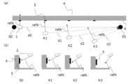
次に、検出面6が平面である場合の飛行体1の制御方法について説明する。はじめに従来の制御方法について説明する。図4は、飛行体1の従来の制御方法について説明するための図である。図4(a)は模式的平面図であり、図4(b)は模式的側面図である。図4の例では、複数の検出対象領域5が直線状に並ぶように配置されている。各検出対象領域5の検出方向は、検出面6に対して垂直である。複数の検出対象領域5の検出方向は互いに等しい。
<Conventional Aircraft Control Method>
Next, a method for controlling the flying object 1 when the detection surface 6 is a plane will be described. First, a conventional control method will be described. FIG. 4 is a diagram for explaining a conventional control method for the flying object 1. FIG. 4(a) is a schematic plan view, and FIG. 4(b) is a schematic side view. In the example of FIG. 4, a plurality of detection target areas 5 are arranged so as to be aligned in a straight line. The detection direction of each detection target area 5 is perpendicular to the detection surface 6. The detection directions of the plurality of detection target areas 5 are the same as each other.

位置S0と位置E0とを結ぶ直線d0上の経路が、飛行開始時点で予定される飛行体1の飛行経路(以下、予定飛行経路と呼ぶ。)である。位置S0は飛行開始位置であり、位置E0は目的位置である。また、本例では、飛行管制部2は、目的位置(位置E0)を一定として飛行体1を制御する。 The path on the straight line d0 connecting position S0 and position E0 is the flight path of the aircraft 1 planned at the start of flight (hereinafter referred to as the planned flight path). Position S0 is the flight start position, and position E0 is the destination position. In this example, the flight control unit 2 controls the aircraft 1 with the destination position (position E0) kept constant.

図4(a)に示すように、飛行体1が、位置S0と位置E0とを結ぶ直線d0に沿って飛行する場合、飛行体1の飛行方向が一定のため、飛行体1の姿勢も一定となる。これにより、検出部15の基準軸refAの方向も一定となる。この場合、検出面6は平面であるので、各検出対象領域5に対する基準軸refAの角度も一定である。 As shown in FIG. 4(a), when the aircraft 1 flies along a straight line d0 connecting positions S0 and E0, the flying direction of the aircraft 1 is constant, and therefore the attitude of the aircraft 1 is also constant. As a result, the direction of the reference axis refA of the detection unit 15 is also constant. In this case, since the detection surface 6 is a flat surface, the angle of the reference axis refA with respect to each detection target area 5 is also constant.

風などの外乱で、飛行体1が予定飛行経路から外れた位置K1に流された場合について説明する。位置E0が固定されているため、飛行管制部2は、飛行体1の飛行方向が、位置K1から位置E0に向かう方向d1となるように制御する。この時、飛行体1の姿勢が変化するので、検出対象領域5に対する検出部15の基準軸refAの角度も変化する。位置K1においては、予定飛行経路からのずれが小さいため検出対象領域5に対する検出部15の基準軸refAの角度の変化も小さい。 We will explain the case where the flying object 1 is blown to position K1, deviating from the planned flight path, due to external disturbances such as wind. Since position E0 is fixed, the flight control unit 2 controls the flight direction of the flying object 1 to be direction d1 from position K1 toward position E0. At this time, the attitude of the flying object 1 changes, and so does the angle of the reference axis refA of the detection unit 15 relative to the detection target area 5. At position K1, the deviation from the planned flight path is small, so the change in the angle of the reference axis refA of the detection unit 15 relative to the detection target area 5 is also small.

飛行体1が、予定飛行経路からさらに離れた位置K2に流された場合について説明する。位置E0が固定されているため、飛行管制部2は、飛行体1の飛行方向が、位置K2から位置E0に向かう方向d2となるように制御する。この時、飛行体1の姿勢の変化も大きくなり、検出対象領域5に対する検出部15の基準軸refAの角度の変化も大きくなる。 We will now explain the case where the flying object 1 is swept away from the planned flight path to position K2. Since position E0 is fixed, the flight control unit 2 controls the flight direction of the flying object 1 to be direction d2 from position K2 toward position E0. At this time, the change in the attitude of the flying object 1 also becomes large, and the change in the angle of the reference axis refA of the detection unit 15 relative to the detection target area 5 also becomes large.

さらに、飛行体1が、位置K3に流された場合、飛行体1の姿勢の変化がさらに大きくなり、検出対象領域5に対する検出部15の基準軸refAの角度の変化がさらに大きくなる。 Furthermore, if the flying object 1 is swept to position K3, the change in the attitude of the flying object 1 becomes even larger, and the change in the angle of the reference axis refA of the detection unit 15 relative to the detection target area 5 becomes even larger.

図4(b)には、飛行体1が位置S0,K1,K2,K3にある時の側方から見た飛行体1と検出対象領域5との関係が示される。図4(b)に示すように、側方から見ても、飛行体1が予定飛行経路から外れるほど、飛行体1の姿勢の変化が大きくなり、検出対象領域5に対する検出部15の基準軸refAの角度の変化が大きくなる。 Figure 4(b) shows the relationship between the aircraft 1 and the detection target area 5 as viewed from the side when the aircraft 1 is at positions S0, K1, K2, and K3. As shown in Figure 4(b), even when viewed from the side, the more the aircraft 1 deviates from the planned flight path, the greater the change in attitude of the aircraft 1 and the greater the change in the angle of the reference axis refA of the detection unit 15 relative to the detection target area 5.

各検出対象領域5から適切に対象物情報を検出するためには、各検出対象領域5に対して適切な方向から対象物情報を検出する必要がある。すなわち、検出対象領域5に対する検出部15の基準軸refAの角度が一定の範囲内にある必要がある。図4の例のように、目的位置が一定であると、飛行体1が予定飛行経路から外れた場合に検出対象領域5に対する検出部15の基準軸refAの角度の変化が大きくなり、検出対象領域5から適切に対象物情報を検出できない。 In order to properly detect object information from each detection target area 5, it is necessary to detect the object information from an appropriate direction for each detection target area 5. That is, the angle of the reference axis refA of the detection unit 15 relative to the detection target area 5 must be within a certain range. As in the example of Figure 4, if the target position is constant, when the flying object 1 deviates from the planned flight path, the change in the angle of the reference axis refA of the detection unit 15 relative to the detection target area 5 becomes large, and object information cannot be properly detected from the detection target area 5.

<実施の形態1の制御例1>
次に、実施の形態1の制御例1に係る飛行体1の制御方法について説明する。図5は、実施の形態1の制御例1に係る飛行体1の制御方法について説明するための図である。図5(a)は模式的平面図であり、図5(b)は模式的側面図である。図4の例と同様に、位置S0は飛行開始位置であり、位置E0は目的位置である。
<Control Example 1 of First Embodiment>
Next, a control method of the flying object 1 according to the control example 1 of the embodiment 1 will be described. Fig. 5 is a diagram for explaining a control method of the flying object 1 according to the control example 1 of the embodiment 1. Fig. 5(a) is a schematic plan view, and Fig. 5(b) is a schematic side view. As in the example of Fig. 4, position S0 is the flight start position, and position E0 is the destination position.

上記のように、飛行管制部2(図1)の飛行計画部21は、垂直方向判定範囲および平行方向判定範囲を第2の範囲として決定する。図5の例では、判定面LY1と判定面LY2との間の領域が垂直方向判定範囲に設定される。判定面LY1、LY2の各々は、検出面6と平行である。判定面LY2と検出面6との間の距離は、判定面LY1と検出面6との間の距離よりも大きい。また、判定面LZ1と判定面LZ2との間の領域が平行方向判定範囲に設定される。判定面LZ1、LZ2の各々は、検出面6に対して垂直である。判定面LZ1の高さは、判定面LZ2の高さよりも高い。飛行管制部2の判定部22は、第2の飛行情報に含まれる、飛行体1の飛行位置が垂直方向判定範囲内にあるか否かを判定するとともに、第2の飛行情報に含まれる飛行体1の飛行位置が平行方向判定範囲内にあるか否かを判定する。以下の説明において、飛行体1の飛行位置が第2の範囲内にあるとは、飛行体1の飛行位置が垂直方向判定範囲内にありかつ平行方向判定範囲内にあることを意味する。 As described above, the flight planning unit 21 of the flight control unit 2 (FIG. 1) determines the vertical direction judgment range and the parallel direction judgment range as the second range. In the example of FIG. 5, the area between the judgment plane LY1 and the judgment plane LY2 is set as the vertical direction judgment range. Each of the judgment planes LY1 and LY2 is parallel to the detection plane 6. The distance between the judgment plane LY2 and the detection plane 6 is greater than the distance between the judgment plane LY1 and the detection plane 6. In addition, the area between the judgment plane LZ1 and the judgment plane LZ2 is set as the parallel direction judgment range. Each of the judgment planes LZ1 and LZ2 is perpendicular to the detection plane 6. The height of the judgment plane LZ1 is higher than the height of the judgment plane LZ2. The judgment unit 22 of the flight control unit 2 judges whether the flight position of the flying object 1 included in the second flight information is within the vertical direction judgment range, and judges whether the flight position of the flying object 1 included in the second flight information is within the parallel direction judgment range. In the following description, the flight position of the aircraft 1 being within the second range means that the flight position of the aircraft 1 is within the vertical direction determination range and within the parallel direction determination range.

各検出対象領域5には、検出方向5vnが予め定められる。nは自然数で、複数の検出対象領域5の各々に割り当てられる。図5の例では、複数の検出対象領域5の検出方向5vnは互いに同じであり、検出面6に垂直な方向である。但し、図5では、5v1および5v2の表記は、省略されている。 A detection direction 5vn is predefined for each detection target area 5. n is a natural number that is assigned to each of the multiple detection target areas 5. In the example of FIG. 5, the detection directions 5vn of the multiple detection target areas 5 are the same and are perpendicular to the detection surface 6. However, in FIG. 5, the notations 5v1 and 5v2 are omitted.

本実施の形態では、第2の飛行情報に含まれる飛行体1の飛行位置が、飛行管制部2の判定部22により、第2の範囲内と判定された場合、飛行管制部2は、検出部15の基準軸refAと検出対象領域5の各々に設定された検出方向5vnとがなす角度が予め定められた第1の範囲内となるように飛行体1の飛行方向を制御する。第1の範囲は、検出部15が検出対象領域5から対象物情報を適切に検出可能な角度範囲に定められる。実施の形態1の制御例1においては、飛行体1の飛行位置が第2の範囲内にある場合、飛行方向が方向d0で一定となるように飛行体1が制御される。 In this embodiment, when the flight position of the flying object 1 included in the second flight information is determined to be within the second range by the determination unit 22 of the flight control unit 2, the flight control unit 2 controls the flight direction of the flying object 1 so that the angle between the reference axis refA of the detection unit 15 and the detection direction 5vn set for each of the detection target areas 5 is within a predetermined first range. The first range is set to an angle range in which the detection unit 15 can appropriately detect object information from the detection target area 5. In control example 1 of embodiment 1, when the flight position of the flying object 1 is within the second range, the flying object 1 is controlled so that the flight direction is constant in direction d0.

図1を参照しながら、具体的な制御の流れを説明する。飛行情報処理部3により取得された飛行体1の飛行位置を含む第2の飛行情報が、飛行管制部2の判定部22および飛行体1の位置測位処理部18へ入力される。判定部22は、第2の飛行情報に含まれる飛行体1の飛行位置が、第2の範囲内であるか判定する。飛行体1の飛行位置が第2の範囲内にあると判定された場合、経路誘導生成部23は、飛行体1の飛行方向を方向d0とする飛行指令値を生成する。生成された飛行指令値は飛行体1の移動・速度指令値生成部17に入力される。 A specific control flow will be described with reference to FIG. 1. Second flight information including the flight position of the aircraft 1 acquired by the flight information processing unit 3 is input to the determination unit 22 of the flight control unit 2 and the positioning processing unit 18 of the aircraft 1. The determination unit 22 determines whether the flight position of the aircraft 1 included in the second flight information is within the second range. If it is determined that the flight position of the aircraft 1 is within the second range, the route guidance generation unit 23 generates a flight command value with the flight direction of the aircraft 1 as direction d0. The generated flight command value is input to the movement/speed command value generation unit 17 of the aircraft 1.

移動・速度指令値生成部17は、経路誘導生成部23により生成された飛行指令値と位置測位処理部18で処理された第2の飛行情報とに基づいて、飛行体1の制御に必要な移動・速度指令値を生成する。生成された移動・速度指令値は姿勢制御部13に入力される。なお、位置測位処理部18からの第2の飛行情報は、目的位置を指定して飛行方向を変更する場合に必要であるので、本制御例1では、飛行体1が位置測位処理部18を備えなくてもよい。 The movement/speed command value generator 17 generates movement/speed command values necessary for controlling the flying object 1 based on the flight command values generated by the route guidance generator 23 and the second flight information processed by the positioning processor 18. The generated movement/speed command values are input to the attitude controller 13. Note that since the second flight information from the positioning processor 18 is necessary when specifying a destination position and changing the flight direction, in this control example 1, the flying object 1 does not need to be equipped with the positioning processor 18.

姿勢制御部13は、移動・速度指令値生成部17により生成された移動・速度指令値と、慣性センサー12により検出された第1の飛行情報に含まれる姿勢とに基づいて、各モーター112の回転数を決定する。 The attitude control unit 13 determines the rotation speed of each motor 112 based on the movement/speed command value generated by the movement/speed command value generation unit 17 and the attitude included in the first flight information detected by the inertial sensor 12.

飛行体1は、飛行方向が一定となるように制御されるため、飛行体1の本体部10の姿勢が一定となる。それにより、本体部10に取り付けられた検出部15の基準軸refAの向きも一定となる。したがって、検出部15の基準軸refAと検出面6上の、複数の検出対象領域5の検出方向5vnとがなす角度も一定となる。 Since the flying object 1 is controlled to keep its flight direction constant, the attitude of the main body 10 of the flying object 1 is constant. As a result, the orientation of the reference axis refA of the detection unit 15 attached to the main body 10 is also constant. Therefore, the angle between the reference axis refA of the detection unit 15 and the detection direction 5vn of the multiple detection target areas 5 on the detection surface 6 is also constant.

図5を参照しながら、風などの外乱により流されて当初の予定飛行経路から外れた場合について具体的に説明する。風などの外乱により飛行体1が、第2の範囲内の位置K1に流されたとする。飛行位置K1が、判定部22により第2の範囲内にあると判定された場合、飛行管制部2は、飛行体1の飛行方向が方向d0で一定となるように制御する。位置K1での検出部15の基準軸refAの方向は、開始位置S0における検出部15の基準軸refAの方向から変化しない。 With reference to FIG. 5, a specific description will be given of a case where the aircraft 1 is blown away from the originally planned flight path by a disturbance such as wind. Suppose that the aircraft 1 is blown away to position K1 within the second range by a disturbance such as wind. When the determination unit 22 determines that the flight position K1 is within the second range, the flight control unit 2 controls the flight direction of the aircraft 1 to be constant in direction d0. The direction of the reference axis refA of the detection unit 15 at position K1 does not change from the direction of the reference axis refA of the detection unit 15 at the start position S0.

次に、風などの外乱により飛行体1が、予定飛行経路からさらに離れた、位置K2に流された場合について説明する。位置K2も判定部22により第2の範囲内にあると判定され、飛行管制部2は、飛行体1の飛行方向が方向d0で一定となるように制御する。飛行方向一定のため、飛行体1の姿勢も一定となる。位置K2での検出部15の基準軸refAは開始位置S0における検出部15の基準軸refAの方向から変化しない。 Next, we will explain the case where the flying object 1 is blown to position K2, further away from the planned flight path, due to external disturbances such as wind. Position K2 is also determined to be within the second range by the determination unit 22, and the flight control unit 2 controls the flight direction of the flying object 1 to be constant in direction d0. Since the flight direction is constant, the attitude of the flying object 1 is also constant. The reference axis refA of the detection unit 15 at position K2 does not change from the direction of the reference axis refA of the detection unit 15 at the start position S0.

さらに風などの外乱により飛行体1が、第2の範囲内の位置K3に流された場合について説明する。位置K3も第2の範囲内にあると判定されるため、飛行管制部2は、飛行体1の飛行方向が方向d0で一定となるように制御する。位置K3での検出部15の基準軸refAも開始位置S0における検出部15の基準軸refAの方向から変化しない。 Furthermore, a case will be described in which the flying object 1 is blown to position K3 within the second range due to a disturbance such as wind. Since position K3 is also determined to be within the second range, the flight control unit 2 controls the flying direction of the flying object 1 to be constant in direction d0. The reference axis refA of the detection unit 15 at position K3 also does not change from the direction of the reference axis refA of the detection unit 15 at the start position S0.

<飛行位置が第2の範囲から外れた場合の動作>
次に、飛行体1の飛行位置が、第2の範囲から外れていると判定部22により判定された場合について図6を用いて説明する。図6は、飛行体1の飛行位置が第2の範囲から外れた場合の動作を示す模式的平面図である。
<Operation when flight position is outside the second range>
Next, a case where the determination unit 22 determines that the flight position of the flying object 1 is outside the second range will be described with reference to Fig. 6. Fig. 6 is a schematic plan view showing the operation when the flight position of the flying object 1 is outside the second range.

飛行体1の飛行位置が第2の範囲から外れていると判定された場合、検出部15による検出対象領域5からの対象物情報の検出が中断される。飛行位置K4において、第2の範囲から外れたと判定されたとする。飛行管制部2は、第2の範囲内の位置K41を戻り位置として設定し、飛行体1を戻り位置まで飛行するように制御する。飛行体1が、戻り位置K41まで戻った後、検出部15による検出対象領域5からの対象物情報の検出が再開される。なお、検出部15により検出された対象物情報と当該対象物情報検出時の飛行体1の位置に関する情報とが関連づけられていれば、飛行体1が戻り位置まで飛行している間も検出部15による検出が継続されていてもよい。 If it is determined that the flight position of the aircraft 1 is outside the second range, the detection of object information from the detection target area 5 by the detection unit 15 is interrupted. It is assumed that the aircraft 1 is determined to have left the second range at flight position K4. The flight control unit 2 sets position K41 within the second range as the return position, and controls the aircraft 1 to fly to the return position. After the aircraft 1 returns to return position K41, the detection unit 15 resumes detection of object information from the detection target area 5. Note that, as long as the object information detected by the detection unit 15 is associated with information regarding the position of the aircraft 1 at the time the object information was detected, detection by the detection unit 15 may continue while the aircraft 1 is flying to the return position.

<動作フロー>
図7を参照しながら実施の形態1の制御例1の動作フローについて説明する。図7は、実施の形態1の制御例1に係る動作フローを示すフローチャートである。
<Operation flow>
An operation flow of control example 1 of embodiment 1 will be described with reference to Fig. 7. Fig. 7 is a flowchart showing an operation flow according to control example 1 of embodiment 1.

ステップST1において、飛行管制部2は、飛行の開始位置S0、目的位置E0、検出対象領域5の検出順序、検出方向および飛行方向(姿勢)を決定する。例えば、複数の検出対象領域5の一端に位置する検出対象領域5付近に開始位置S0が設定され、他端に位置する検出対象領域5付近に目的位置E0が設定される。 In step ST1, the flight control unit 2 determines the flight start position S0, the destination position E0, the detection order of the detection target area 5, the detection direction, and the flight direction (attitude). For example, the start position S0 is set near the detection target area 5 located at one end of the multiple detection target areas 5, and the destination position E0 is set near the detection target area 5 located at the other end.

次にステップST2において、飛行管制部2は、垂直方向判定範囲および平行方向判定範囲を決定する。 Next, in step ST2, the flight control unit 2 determines the vertical direction judgment range and the horizontal direction judgment range.

次にステップST3において、飛行管制部2が飛行体1に飛行方向を指令する。飛行方向は、開始位置S0から目的位置E0へ向かう方向で、実施の形態1においては検出面6と平行である。 Next, in step ST3, the flight control unit 2 commands the flying direction to the flying object 1. The flying direction is the direction from the starting position S0 to the destination position E0, which is parallel to the detection surface 6 in the first embodiment.

次にステップST4において、飛行管制部2が飛行体1に飛行を開始させ、ステップST5において、検出部15が検出対象領域5からの対象物情報の検出を開始する。飛行体1の飛行中に、検出部15により複数の検出対象領域5から対象物情報が順次検出される。飛行管制部2は、各検出対象領域5の検出方向と、検出部15の基準軸refAとがなす角度が、第1の範囲内になるように、飛行体1の飛行を制御する。 Next, in step ST4, the flight control unit 2 causes the aircraft 1 to start flying, and in step ST5, the detection unit 15 starts detecting object information from the detection target areas 5. While the aircraft 1 is flying, the detection unit 15 sequentially detects object information from the multiple detection target areas 5. The flight control unit 2 controls the flight of the aircraft 1 so that the angle between the detection direction of each detection target area 5 and the reference axis refA of the detection unit 15 is within a first range.

ステップST6において、飛行情報処理部3は、第2の飛行情報を取得する。次にステップST7において、飛行管制部2は、ステップST6で取得された第2の飛行情報に基づいて、その時点での飛行位置が第2の範囲内にあるか否かを判定する。飛行位置が第2の範囲内にある場合(ステップST7 YES)、飛行管制部2は、ステップST8に進み、飛行位置が目的位置に達したか(LXE0を通過したか)否かを判定する。 In step ST6, the flight information processing unit 3 acquires the second flight information. Next, in step ST7, the flight control unit 2 determines whether the flight position at that time is within the second range based on the second flight information acquired in step ST6. If the flight position is within the second range (step ST7 YES), the flight control unit 2 proceeds to step ST8 and determines whether the flight position has reached the destination position (passed LXE0).

飛行位置が目的位置に達している場合(ステップST8 YES)、飛行管制部2は、飛行体1に飛行を終了させる。飛行位置が目的位置に達していない場合(ステップST8 NО)、飛行管制部2がステップST6に戻る。ステップST7において、飛行体1の飛行位置が第2の範囲内にない場合(ステップST7 NО)、飛行管制部2は検出部15による検出対象領域5からの対象物情報の検出を中断し(ステップST9)、飛行管制部2がステップST10に進む。 If the flight position has reached the destination position (step ST8 YES), the flight control unit 2 causes the aircraft 1 to end flight. If the flight position has not reached the destination position (step ST8 NO), the flight control unit 2 returns to step ST6. In step ST7, if the flight position of the aircraft 1 is not within the second range (step ST7 NO), the flight control unit 2 interrupts detection of object information from the detection target area 5 by the detection unit 15 (step ST9), and the flight control unit 2 proceeds to step ST10.

ステップST10において、飛行管制部2は、第2の範囲内の位置を戻り位置として設定し、戻り位置に向かって飛行するように飛行体1を制御する。次にステップST11において、飛行管制部2は、飛行体1が戻り位置に達したか否かを判定する。飛行体1が戻り位置に達するまで、飛行管制部2は、ステップST10、ST11を繰り返す。飛行体1が戻り位置に達すると、飛行管制部2は、ステップST12に進み、飛行体1の飛行方向(姿勢)をステップST3で設定した方向(姿勢)に設定して、検出部15による検出対象領域5からの対象物情報の検出を再開する。 In step ST10, the flight control unit 2 sets a position within the second range as the return position, and controls the aircraft 1 to fly toward the return position. Next, in step ST11, the flight control unit 2 determines whether the aircraft 1 has reached the return position. The flight control unit 2 repeats steps ST10 and ST11 until the aircraft 1 reaches the return position. When the aircraft 1 reaches the return position, the flight control unit 2 proceeds to step ST12, sets the flight direction (attitude) of the aircraft 1 to the direction (attitude) set in step ST3, and resumes detection of object information from the detection target area 5 by the detection unit 15.

<実施の形態1の制御例1の効果>
実施の形態1に係る飛行システムおよびその制御方法においては、空中を飛行する飛行体1の飛行情報が飛行情報処理部3により取得される。飛行情報処理部3により取得された飛行情報に基づいて、飛行管制部2により飛行体1が制御される。飛行体1に設けられた検出部15により飛行体1の飛行中に検出対象物4から対象物情報が検出される。検出部15が複数の検出対象領域5の各々から対象物情報を検出する時に、複数の検出対象領域5の各々に対して予め定められた検出方向と、検出部15の基準軸refAとがなす角度が、予め定められた第1の範囲内となるように、飛行体1が制御される。
<Effects of Control Example 1 of First Embodiment>
In the flight system and control method according to the first embodiment, flight information of the aircraft 1 flying in the air is acquired by the flight information processing unit 3. The aircraft 1 is controlled by the flight control unit 2 based on the flight information acquired by the flight information processing unit 3. A detection unit 15 provided in the aircraft 1 detects object information from a detection target 4 during the flight of the aircraft 1. When the detection unit 15 detects object information from each of a plurality of detection target areas 5, the aircraft 1 is controlled so that an angle formed between a detection direction predetermined for each of the plurality of detection target areas 5 and a reference axis refA of the detection unit 15 falls within a predetermined first range.

このような構成により、複数の検出対象領域5に対する検出部15の姿勢を適切に維持しながら対象物情報を検出することができる。それにより、飛行体1により取得すべき対象物情報を適切に取得することが可能となる。 This configuration allows the detection unit 15 to detect object information while appropriately maintaining the orientation of the detection unit 15 relative to the multiple detection target areas 5. This makes it possible to appropriately acquire the object information that should be acquired by the flying object 1.

また、実施の形態1の制御例1においては、飛行管制部2は、複数の検出対象領域5の位置および検出方向、ならびに検出部15による複数の検出対象領域5の検出の順序に基づいて、飛行体1の飛行経路を決定し、決定した飛行経路に沿って飛行するように飛行体1を制御する。これにより、各検出対象領域5に対する検出部15の姿勢を適切に維持しながら飛行体1を飛行させることができる。 In addition, in control example 1 of embodiment 1, the flight control unit 2 determines the flight path of the aircraft 1 based on the positions and detection directions of the multiple detection target areas 5 and the order in which the detection unit 15 detects the multiple detection target areas 5, and controls the aircraft 1 to fly along the determined flight path. This allows the aircraft 1 to fly while appropriately maintaining the attitude of the detection unit 15 relative to each detection target area 5.

また、実施の形態1においては、飛行体1の飛行位置の適正範囲が第2の範囲として定められる。飛行システム100は、飛行情報処理部3により取得された飛行情報に基づいて、飛行体1の飛行位置が第2の範囲内にあるか否かを判定する第1の判定部22をさらに備え、判定部22により飛行体1の飛行位置が第2の範囲内にないと判定された場合、飛行管制部2は、飛行体1の飛行位置が第2の範囲内になるように、飛行体1を制御する。これにより、検出部15と各検出対象領域5との距離が、対象物の検出に適した範囲内に保たれる。その結果、飛行体1により取得すべき対象物情報適切に取得することができる。 In addition, in the first embodiment, the appropriate range for the flight position of the aircraft 1 is determined as the second range. The flight system 100 further includes a first determination unit 22 that determines whether the flight position of the aircraft 1 is within the second range based on the flight information acquired by the flight information processing unit 3, and if the determination unit 22 determines that the flight position of the aircraft 1 is not within the second range, the flight control unit 2 controls the aircraft 1 so that the flight position of the aircraft 1 is within the second range. This keeps the distance between the detection unit 15 and each detection target area 5 within a range suitable for detecting the target object. As a result, the target object information that should be acquired by the aircraft 1 can be appropriately acquired.

また、実施の形態1においては、検出部15は、検出対象領域5を撮像することにより検出対象領域5の画像データを対象物情報として検出する撮像部を含む。撮像部は、予め定められた画角および予め定められた焦点深度を有し、第2の範囲は、撮像部の画角および焦点深度に基づいて定められる。これにより、飛行体1が、第2の範囲内を飛行していれば、検出対象領域5全体が、検出部15の検出範囲に入り、検出部15により検出対象領域5から対象物情報が取得される。 In addition, in the first embodiment, the detection unit 15 includes an imaging unit that captures an image of the detection target area 5 to detect image data of the detection target area 5 as object information. The imaging unit has a predetermined angle of view and a predetermined focal depth, and the second range is determined based on the angle of view and focal depth of the imaging unit. As a result, if the flying object 1 is flying within the second range, the entire detection target area 5 falls within the detection range of the detection unit 15, and the detection unit 15 acquires object information from the detection target area 5.

また、実施の形態1に係る飛行システムにおいては、複数の検出対象領域5の検出方向は、互いに等しい。これにより、飛行管制部2は、検出部15が複数の検出対象領域5の各々から対象物情報を検出する時に、飛行体1の飛行方向を一定方向となるように制御することができ、制御負荷を軽減できる。 In addition, in the flight system according to the first embodiment, the detection directions of the multiple detection target areas 5 are the same. This allows the flight control unit 2 to control the flight direction of the aircraft 1 to be constant when the detection unit 15 detects object information from each of the multiple detection target areas 5, thereby reducing the control load.

飛行体1は、複数のプロペラを備えた無人飛行体であり、複数のプロペラ111の回転軸の位置は、飛行体1に対して固定されており、飛行管制部2は、複数のプロペラ111の回転数差で飛行体1の飛行方向を制御する。これにより、有人飛行体では近寄れないような狭小な検出対象物からも検出部15により検出対象領域5から対象物情報が取得される。 The aircraft 1 is an unmanned aircraft equipped with multiple propellers, and the position of the rotation axis of the multiple propellers 111 is fixed relative to the aircraft 1, and the flight control unit 2 controls the flight direction of the aircraft 1 by the difference in the rotation speed of the multiple propellers 111. This allows the detection unit 15 to obtain object information from the detection target area 5 even for small detection objects that cannot be approached by manned aircraft.

<実施の形態1の制御例2>
本実施の形態の制御例2について、上記制御例1と異なる点を中心に説明する。制御例2においては、各検出対象領域5の検出方向と、検出部15の基準軸refAとがなす角度が、第1の範囲内となるように、飛行管制部2が、目的位置を補正し、補正した目的位置に向かうように飛行体1の飛行方向を制御する。例えば、第2の飛行情報に含まれる飛行体1の飛行位置が第2の範囲内にあると判定された場合、飛行管制部2は、飛行体1の飛行方向が一定となるように飛行体1の飛行位置に基づいて目的位置を変更する。図8を参照しながら、風などの外乱により流されて当初の予定飛行経路から外れた場合について具体的に説明する。図8において、飛行開始時の目的位置E0を通り検出面5と垂直な線をLXE0とする。
<Control Example 2 of First Embodiment>
A control example 2 of this embodiment will be described focusing on the differences from the control example 1. In the control example 2, the flight control unit 2 corrects the target position so that the angle between the detection direction of each detection target area 5 and the reference axis refA of the detection unit 15 is within the first range, and controls the flight direction of the aircraft 1 to head toward the corrected target position. For example, when it is determined that the flight position of the aircraft 1 included in the second flight information is within the second range, the flight control unit 2 changes the target position based on the flight position of the aircraft 1 so that the flight direction of the aircraft 1 is constant. With reference to FIG. 8, a case where the aircraft 1 is blown away by disturbances such as wind and deviates from the initial planned flight path will be specifically described. In FIG. 8, a line passing through the target position E0 at the start of flight and perpendicular to the detection surface 5 is designated as LXE0.

飛行体1が位置K1に流されたとする。飛行体1の飛行位置K1が、判定部22により第2の範囲内にあると判定された場合、飛行管制部2は、位置K1を通り、方向d0と平行な直線と直線LXE0との交点E1を新しい目的位置として設定し、飛行体1へ指令する。飛行体1は、飛行方向一定で飛行を継続することとなる。飛行体1の本体部10の姿勢に変化はないため、検出部15の基準軸refAの方向は、開始位置S0における検出部15の基準軸refAの方向から変化しない。 Suppose that the aircraft 1 is drifted to position K1. If the determination unit 22 determines that the flight position K1 of the aircraft 1 is within the second range, the flight control unit 2 sets the intersection E1 of a line that passes through position K1 and is parallel to direction d0 and the line LXE0 as a new destination position and issues a command to the aircraft 1. The aircraft 1 continues flying with a constant flight direction. Since there is no change in the attitude of the main body unit 10 of the aircraft 1, the direction of the reference axis refA of the detection unit 15 does not change from the direction of the reference axis refA of the detection unit 15 at the start position S0.

次に、風などの外乱により飛行体1が予定飛行経路からさらに離れた位置K2に流された場合について説明する。位置K2も判定部22により第2の範囲内にあると判定され、飛行管制部2は、位置K2を通り、方向d0と平行な直線と直線LXE0との交点E2を新しい目的位置として設定し、飛行体1へ指令する。飛行体1は、飛行方向一定で飛行を継続することとなる。飛行体1の本体部10の姿勢に変化はないため、検出部15の基準軸refAの方向は、開始位置S0における検出部15の基準軸refAの方向から変化しない。 Next, we will explain the case where the flying object 1 is blown to position K2, further away from the planned flight path, due to disturbances such as wind. Position K2 is also determined to be within the second range by the determination unit 22, and the flight control unit 2 sets the intersection E2 of a line that passes through position K2 and is parallel to direction d0 and the line LXE0 as the new destination position and issues a command to the flying object 1. The flying object 1 will continue flying with a constant flight direction. Since there is no change in the attitude of the main body unit 10 of the flying object 1, the direction of the reference axis refA of the detection unit 15 does not change from the direction of the reference axis refA of the detection unit 15 at the start position S0.

さらに風などの外乱により飛行体1が、位置K3に流された場合について説明する。飛行位置K3も第2の範囲内にあると判定され、飛行管制部2は、位置K3を通り、方向d0と平行な直線とLXE0との交点E3を新しい目的位置として設定し、飛行体1へ指令する。飛行体1は、飛行方向一定で飛行を継続することとなる。飛行体1の本体部10の姿勢に変化はないため、検出部15の基準軸refAの方向は、開始位置S0における検出部15の基準軸refAの方向から変化しない。 Furthermore, a case will be described where the flying object 1 is blown to position K3 due to a disturbance such as wind. Flight position K3 is also determined to be within the second range, and the flight control unit 2 sets the intersection E3 of a line passing through position K3 and parallel to direction d0 with LXE0 as the new destination position, and issues a command to the flying object 1. The flying object 1 will continue flying with a constant flight direction. Since there is no change in the attitude of the main body unit 10 of the flying object 1, the direction of the reference axis refA of the detection unit 15 does not change from the direction of the reference axis refA of the detection unit 15 at the start position S0.

このように、風などの外乱により、飛行開始時の予定飛行経路から外れても、飛行体1の飛行位置が第2の範囲内にあると判定された場合、目的位置が変更され、飛行方向が一定となるように制御される。これにより飛行体1の本体部10の姿勢も一定となり、検出部15の基準軸refAと検出対象領域5の検出方向5vnとがなす角度が、予め定められた第1の範囲内にある状態で飛行が継続される。 In this way, even if the flying object 1 deviates from the planned flight path at the start of flight due to disturbances such as wind, if the flying position of the flying object 1 is determined to be within the second range, the destination position is changed and the flying direction is controlled to be constant. This also keeps the attitude of the main body 10 of the flying object 1 constant, and flight continues with the angle between the reference axis refA of the detection unit 15 and the detection direction 5vn of the detection target area 5 within the predetermined first range.

<動作フロー>
図9を参照しながら実施の形態1の制御例2の動作フローについて、図7の動作フローと異なる点を説明する。図9は、実施の形態1の制御例2の動作フローを説明するフローチャートである。制御例1の動作フロー(図7)では、ステップST8において、飛行位置が目的位置に達していない場合、飛行管制部2がステップST6に戻る。それに対して、制御例2では、ステップST8において飛行位置が目的位置に達していない場合、飛行管制部2が、ステップST13に進む。ステップST13において、飛行管制部2は、飛行体1の飛行方向が一定となるように、飛行位置に基づいて、目的位置を変更し、ステップST6に戻る。
<Operation flow>
With reference to FIG. 9, differences between the operation flow of control example 2 of embodiment 1 and the operation flow of FIG. 7 will be described. FIG. 9 is a flowchart for explaining the operation flow of control example 2 of embodiment 1. In the operation flow of control example 1 (FIG. 7), if the flight position has not reached the target position in step ST8, the flight control unit 2 returns to step ST6. In contrast, in control example 2, if the flight position has not reached the target position in step ST8, the flight control unit 2 proceeds to step ST13. In step ST13, the flight control unit 2 changes the target position based on the flight position so that the flight direction of the aircraft 1 is constant, and returns to step ST6.

<実施の形態1の制御例2の効果>
実施の形態1の制御例2においても、制御例1と同様に、検出部15が複数の検出対象領域5の各々から対象物情報を検出する時に、複数の検出対象領域5の各々に対して予め定められた検出方向と、検出部15の基準軸refAとがなす角度が、予め定められた第1の範囲内となるように、飛行体1が制御される。これにより、複数の検出対象領域5に対する検出部15の姿勢を適切に維持しながら対象物情報を検出することができる。それにより、飛行体1により取得すべき対象物情報を適切に取得することが可能となる。
<Effects of Control Example 2 of First Embodiment>
In Control Example 2 of Embodiment 1, similarly to Control Example 1, the aircraft 1 is controlled so that when the detection unit 15 detects object information from each of the plurality of detection target areas 5, the angle between a predetermined detection direction for each of the plurality of detection target areas 5 and the reference axis refA of the detection unit 15 is within a predetermined first range. This makes it possible to detect object information while appropriately maintaining the attitude of the detection unit 15 with respect to the plurality of detection target areas 5. This makes it possible to appropriately acquire object information that should be acquired by the aircraft 1.

また、実施の形態1の制御例2においては、飛行管制部2により飛行体1の目的位置が取得され、複数の検出対象領域5の各々に対して予め定められた検出方向と、検出部15の基準軸refAとがなす角度が第1の範囲内となるように、取得された目的位置が補正され、補正された目的位置に向かうように飛行体1の飛行方向が制御される。これにより、飛行体1は、飛行方向が一定となるように制御されるため制御負荷を軽減可能である。 In addition, in control example 2 of embodiment 1, the flight control unit 2 acquires the destination position of the aircraft 1, corrects the acquired destination position so that the angle between the detection direction predetermined for each of the multiple detection target areas 5 and the reference axis refA of the detection unit 15 is within a first range, and controls the flight direction of the aircraft 1 so that it heads toward the corrected destination position. This allows the aircraft 1 to be controlled so that its flight direction is constant, reducing the control load.

実施の形態2.
以下、実施の形態2に係る飛行システム100について、実施の形態1との相違点を中心に説明する。実施の形態2に係る飛行システム100の構成は、図1に示した構成と同じである。実施の形態1では、複数の検出対象領域5が、検出対象物4の平面上に配置されており、複数の検出対象領域5の検出方向が互いに等しい。それに対して、実施の形態2では、複数の検出対象領域5が、検出対象物4の曲面上に配置されており、複数の検出対象領域5のうち少なくとも2つの検出対象領域5の検出方向が互いに異なる。
Embodiment 2.
The flight system 100 according to the second embodiment will be described below, focusing on the differences from the first embodiment. The configuration of the flight system 100 according to the second embodiment is the same as the configuration shown in Fig. 1. In the first embodiment, the multiple detection target areas 5 are arranged on a flat surface of the detection target object 4, and the detection directions of the multiple detection target areas 5 are the same. In contrast, in the second embodiment, the multiple detection target areas 5 are arranged on a curved surface of the detection target object 4, and the detection directions of at least two of the multiple detection target areas 5 are different from each other.

<実施の形態2の制御例1>
図10は、実施の形態2の制御例1について説明するための模式的平面図である。本例では、理解を容易にするため、飛行体1および各検出対象領域5が共通の平面(水平面)上にあると仮定し、二次元上でのこれらの関係を説明する。図10の例では、検出対象物4が略円弧状の外面を有し、その外面上に複数の検出対象領域5が周方向に沿って配置される。検出面6は、略円弧状の外面に設定される。検出面6と間隔をおいて周方向に沿うように、飛行体1の予定飛行経路が設定される。予定飛行経路は、開始位置S0と経由位置W0、W1、W2、W3とを含む。経由位置W0、W1、W2、W3は、飛行体1が経由すべき位置である。隣り合う経由位置間の距離が、隣り合う経由位置間の飛行経路の長さと同等となるように、検出面6の曲率が大きいほど隣り合う経由位置間の距離も大きく設定可能である。
<Control Example 1 of Second Embodiment>
FIG. 10 is a schematic plan view for explaining a control example 1 of the second embodiment. In this example, for ease of understanding, it is assumed that the flying object 1 and each detection target area 5 are on a common plane (horizontal plane), and their relationship in two dimensions is explained. In the example of FIG. 10, the detection target object 4 has a substantially arc-shaped outer surface, and a plurality of detection target areas 5 are arranged along the circumferential direction on the outer surface. The detection surface 6 is set on the substantially arc-shaped outer surface. The planned flight path of the flying object 1 is set so as to be spaced apart from the detection surface 6 and along the circumferential direction. The planned flight path includes a start position S0 and via positions W0, W1, W2, and W3. The via positions W0, W1, W2, and W3 are positions through which the flying object 1 should pass. The greater the curvature of the detection surface 6, the greater the distance between adjacent via positions can be set so that the distance between adjacent via positions is equivalent to the length of the flight path between the adjacent via positions.

図10においては、経由位置W0を通り検出面6に垂直な直線をLXW0、経由位置W1を通り検出面6に垂直な直線をLXW1、経由位置W2を通り検出面6に垂直な直線をLXW2、経由位置W3を通り検出面6に垂直な直線をLXW3とする。 In FIG. 10, the line passing through via position W0 and perpendicular to detection surface 6 is LXW0, the line passing through via position W1 and perpendicular to detection surface 6 is LXW1, the line passing through via position W2 and perpendicular to detection surface 6 is LXW2, and the line passing through via position W3 and perpendicular to detection surface 6 is LXW3.

複数の経由位置は、例えば、複数の検出対象領域5の位置に基づいて決定される。図10の例では、検出対象領域51が検出されるように経由位置W0と経由位置W1とが設定され、検出対象領域52が検出されるように経由位置W1と経由位置W2とが設定され、検出対象領域53が検出されるように経由位置W2と経由位置W3とが設定される。 The multiple via positions are determined, for example, based on the positions of the multiple detection target areas 5. In the example of FIG. 10, via positions W0 and W1 are set so that detection target area 51 is detected, via positions W1 and W2 are set so that detection target area 52 is detected, and via positions W2 and W3 are set so that detection target area 53 is detected.

各経由位置から次の経由位置までの区間における飛行速度および飛行方向等が予め設定されてもよい。なお、図6の例では、経由位置が設定されないが、検出面6が平面である場合にも、飛行開始位置と飛行終了位置との間に1または複数の経由位置が設定されてもよい。また、図10の例では、隣り合う経由位置の間の各区間に対応して1つの検出対象領域5が設けられるが、各区間に対応して複数の検出対象領域5が設けられていてもよいし、対応する検出対象領域5が存在しない区間があってもよい。 The flight speed and flight direction in the section from each waypoint to the next waypoint may be set in advance. In the example of FIG. 6, no waypoints are set, but even if the detection surface 6 is flat, one or more waypoints may be set between the flight start position and the flight end position. In the example of FIG. 10, one detection target area 5 is provided corresponding to each section between adjacent waypoints, but multiple detection target areas 5 may be provided corresponding to each section, and there may be a section where no corresponding detection target area 5 exists.

図11は、実施の形態2の制御例1における飛行体1の飛行方向を示す模式的平面図である。飛行体1が、経由位置W1と経由位置W2との間の区間で、検出面6に垂直でかつ検出対象領域5を通る直線LXW11上の位置K11を飛行しているとする。本例において、各検出対象領域5の検出方向は、その検出対象領域5が設けられた検出面6の部分に垂直な方向である。また、検出部15の基準軸refAは、飛行体1の進行方向に対して垂直である。制御例1では、飛行体1は、飛行方向d11が、直線LXW11と垂直な方向となるように制御される。 Figure 11 is a schematic plan view showing the flight direction of the aircraft 1 in control example 1 of embodiment 2. The aircraft 1 is assumed to fly at position K11 on a straight line LXW11 that is perpendicular to the detection surface 6 and passes through the detection target area 5 in the section between via position W1 and via position W2. In this example, the detection direction of each detection target area 5 is a direction perpendicular to the part of the detection surface 6 in which the detection target area 5 is provided. The reference axis refA of the detection unit 15 is also perpendicular to the traveling direction of the aircraft 1. In control example 1, the aircraft 1 is controlled so that the flight direction d11 is perpendicular to the straight line LXW11.

例えば、複数の検出対象領域5が、共通の水平面上で一定の曲率を有する第1の円に沿って配置される場合、平面視において第1の円の少なくとも一部に相当するように検出面6が設定される。その場合、飛行体1は、第1の円と同心でかつ第1の円よりも大きい半径を有する第2の円に沿って飛行する。飛行体1の飛行速度は、第2の円の中心軸周りの飛行体1の角速度と、飛行体1のヨー速度(ヨーレート)とが一致するように決定される。 For example, when multiple detection target regions 5 are arranged along a first circle having a constant curvature on a common horizontal plane, the detection surface 6 is set to correspond to at least a part of the first circle in a planar view. In this case, the flying object 1 flies along a second circle that is concentric with the first circle and has a larger radius than the first circle. The flight speed of the flying object 1 is determined so that the angular velocity of the flying object 1 around the central axis of the second circle matches the yaw speed (yaw rate) of the flying object 1.

このように飛行体1が制御されることで、飛行体1は、曲面状の検出面6に沿って曲線状に飛行し、検出面6に対して一定の向きを保って飛行する。これにより、検出部15による各検出対象領域5からの対象物情報の検出時に、検出部15の基準軸refAと、検出対象領域5の検出方向とがなす角度が、第1の範囲内となる。風などの外乱により飛行体1が、第2の範囲の外に流された場合、実施の形態1と同様の方法で第2の範囲内に飛行体1が戻される。 By controlling the flying object 1 in this manner, the flying object 1 flies in a curved manner along the curved detection surface 6, and maintains a constant orientation relative to the detection surface 6. As a result, when the detection unit 15 detects object information from each detection target area 5, the angle between the reference axis refA of the detection unit 15 and the detection direction of the detection target area 5 falls within the first range. If the flying object 1 is blown out of the second range by an external disturbance such as wind, the flying object 1 is returned to within the second range in the same manner as in embodiment 1.

<動作フロー>
図12を参照しながら実施の形態2の制御例1の動作フローについて、図7の動作フローと異なる点を説明する。図12は、実施の形態2の制御例1の動作フローを示すフローチャートである。実施の形態1の制御例1(図7)では、ステップST3において、飛行管制部2は、飛行位置に関わらず飛行方向が一定となるように飛行体1を制御する。それに対して、本実施の形態の制御例1では、ステップST3の代わりにステップST3aが実施され、ステップST3aにおいて、飛行管制部2は、飛行位置に基づいて飛行体1の飛行方向、飛行速度およびヨー角を指令する。
<Operation flow>
With reference to Fig. 12, the operation flow of control example 1 of embodiment 2 will be described with respect to differences from the operation flow of Fig. 7. Fig. 12 is a flowchart showing the operation flow of control example 1 of embodiment 2. In control example 1 of embodiment 1 (Fig. 7), in step ST3, the flight control unit 2 controls the flying object 1 so that the flight direction is constant regardless of the flight position. In contrast, in control example 1 of this embodiment, step ST3a is performed instead of step ST3, and in step ST3a, the flight control unit 2 commands the flight direction, flight speed, and yaw angle of the flying object 1 based on the flight position.

実施の形態1の制御例1(図7)では、ステップST8において、飛行位置が目的位置に達していない場合、飛行管制部2がステップST6に戻る。それに対して、本実施の形態の制御例1では、飛行管制部2がステップST13aに進む。ステップST13aにおいて、飛行管制部2は、飛行体1の飛行方向が一定となるように、飛行位置に基づいて飛行方向、飛行速度およびヨー角を指令し、ステップST6に戻る。 In control example 1 of embodiment 1 (FIG. 7), if the flight position has not reached the target position in step ST8, the flight control unit 2 returns to step ST6. In contrast, in control example 1 of the present embodiment, the flight control unit 2 proceeds to step ST13a. In step ST13a, the flight control unit 2 commands the flight direction, flight speed, and yaw angle based on the flight position so that the flight direction of the flying object 1 is constant, and returns to step ST6.

他のステップは、実施の形態1の制御例1と同様である。 The other steps are the same as in Control Example 1 of Embodiment 1.

<実施の形態2の制御例1の効果>
実施の形態2に係る飛行システムにおいても、実施の形態1と同様に、検出部15が複数の検出対象領域5の各々から対象物情報を検出する時に、複数の検出対象領域5の各々に対して予め定められた検出方向と、検出部15の基準軸refAとがなす角度が、予め定められた第1の範囲内となるように、飛行体1が制御される。これにより、複数の検出対象領域5に対する検出部15の姿勢を適切に維持しながら対象物情報を検出することができる。それにより、飛行体1により取得すべき対象物情報を適切に取得することが可能となる。
<Effects of Control Example 1 of Second Embodiment>
In the flight system according to the second embodiment, similarly to the first embodiment, the flying object 1 is controlled so that when the detection unit 15 detects object information from each of the plurality of detection target areas 5, the angle between the predetermined detection direction for each of the plurality of detection target areas 5 and the reference axis refA of the detection unit 15 is within a predetermined first range. This makes it possible to detect object information while appropriately maintaining the attitude of the detection unit 15 with respect to the plurality of detection target areas 5. This makes it possible to appropriately acquire object information that should be acquired by the flying object 1.

また、実施の形態2においても、実施の形態1と同様に、判定部22により飛行体1の飛行位置が第2の範囲内にないと判定された場合、飛行管制部2は、飛行体1の飛行位置が第2の範囲内になるように、飛行体1を制御する。これにより、検出部15と各検出対象領域5との距離が、対象物の検出に適した範囲内に保たれる。その結果、飛行体1により取得すべき対象物情報を適切に取得することができる。 Also in the second embodiment, as in the first embodiment, if the determination unit 22 determines that the flight position of the aircraft 1 is not within the second range, the flight control unit 2 controls the aircraft 1 so that the flight position of the aircraft 1 is within the second range. This keeps the distance between the detection unit 15 and each detection target area 5 within a range suitable for detecting the target object. As a result, the target object information that should be acquired by the aircraft 1 can be appropriately acquired.

また、実施の形態2の制御例1に係る飛行システムにおいては、複数の検出対象領域5の前記検出方向は、互いに異なる。このような場合、複数の検出対象領域5は、曲面の検出面6上に配置されることになる。検出面6が曲面の場合においても、複数の検出対象領域5の各々に対して予め定められた検出方向と、検出部15の基準軸refAとがなす角度が、予め定められた第1の範囲内となるように、飛行体1は制御される。これにより、検出面6が曲面であっても複数の検出対象領域5に対する検出部15の姿勢を適切に維持しながら対象物情報を検出できる。それにより、飛行体1により取得すべき対象物情報を適切に取得することが可能となる。 In addition, in the flight system according to control example 1 of embodiment 2, the detection directions of the multiple detection target areas 5 are different from each other. In such a case, the multiple detection target areas 5 are arranged on a curved detection surface 6. Even when the detection surface 6 is curved, the flying object 1 is controlled so that the angle between the predetermined detection direction for each of the multiple detection target areas 5 and the reference axis refA of the detection unit 15 is within a predetermined first range. This makes it possible to detect object information while appropriately maintaining the attitude of the detection unit 15 with respect to the multiple detection target areas 5 even when the detection surface 6 is curved. This makes it possible to appropriately acquire object information that should be acquired by the flying object 1.

<実施の形態2の制御例2>
図13を参照しながら、検出面6が、曲面である場合の飛行経路の他の決定方法について、上記制御例1と異なる点を中心に説明する。図13は、実施の形態2の制御例2について説明するための模式的平面図である。
<Control Example 2 of Second Embodiment>
Another method for determining a flight path when the detection surface 6 is a curved surface will be described with reference to Fig. 13, focusing on differences from the above-mentioned Control Example 1. Fig. 13 is a schematic plan view for explaining Control Example 2 of the second embodiment.

第2の実施の形態の制御例2では、第1の経由位置から第2の経由位置まで飛行体1が飛行する期間に、飛行体1が直線的にかつ一定の姿勢で飛行しつつ、検出部15の基準軸refAと経由位置間対象領域の検出方向とがなす角度が、第1の範囲内になるように、飛行体1が制御される。ここで、第1および第2の経由位置とは、通過する順序が互いに連続する経由位置である。経由位置間対象領域とは、飛行体1が第1の経由位置から第2の経由位置まで飛行する期間に検出部15により検出すべき検出対象領域5である。 In control example 2 of the second embodiment, during the period when the aircraft 1 flies from the first via position to the second via position, the aircraft 1 is controlled so that the angle between the reference axis refA of the detection unit 15 and the detection direction of the inter-via position target area is within a first range while the aircraft 1 flies in a straight line with a constant attitude. Here, the first and second via positions are via positions that are passed consecutively. The inter-via position target area is the detection target area 5 that should be detected by the detection unit 15 during the period when the aircraft 1 flies from the first via position to the second via position.

第1の経由位置から第2の経由位置まで飛行体1が直線的にかつ一定の姿勢で飛行する期間には、検出部15の基準軸refAの方向は一定である。その基準軸refAと、経由位置間対象領域の検出方向とがなす角度が、第1の範囲内となるように、飛行管制部2が、第1の経由位置と第2の経由位置とを決定する。 During the period when the aircraft 1 flies in a straight line with a constant attitude from the first via point to the second via point, the direction of the reference axis refA of the detection unit 15 is constant. The flight control unit 2 determines the first via point and the second via point so that the angle between the reference axis refA and the detection direction of the target area between the via points is within a first range.

図13の例では、複数の経由位置間の各区間を飛行体1が飛行する期間に、1つの検出対象領域5が検出される。この場合、複数の経由位置間の各区間において、直線的にかつ一定の姿勢で飛行するように飛行体1が制御される。 In the example of FIG. 13, one detection target area 5 is detected during the period in which the aircraft 1 flies through each section between multiple intermediate positions. In this case, the aircraft 1 is controlled to fly linearly and with a constant attitude through each section between multiple intermediate positions.

開始位置S0と経由位置W0とを結んだ直線の方向を方向d0、経由位置W0と経由位置W1とを結んだ直線の方向を方向d1、経由位置W1と経由位置W2とを結んだ直線の方向を方向d2、経由位置W2と経由位置W3とを結んだ直線の方向を方向d3とする。飛行体1が、開始位置S0と経由位置W0との間に対応する区間を飛行している時、開始位置S0が第1の経由位置、経由位置W1が第2の経由位置となる。同様に、経由位置W1と経由位置W2との間に対応する区間では、経由位置W1が第1の経由位置、経由位置W2が第2の経由位置となり、経由位置W2と経由位置W3との間に対応する区間では、経由位置W2が第1の経由位置、経由位置W3が第2の経由位置となる。 The direction of the line connecting the start position S0 and the via position W0 is direction d0, the direction of the line connecting the via position W0 and the via position W1 is direction d1, the direction of the line connecting the via position W1 and the via position W2 is direction d2, and the direction of the line connecting the via position W2 and the via position W3 is direction d3. When the aircraft 1 is flying in the section corresponding to the start position S0 and the via position W0, the start position S0 is the first via position and the via position W1 is the second via position. Similarly, in the section corresponding to the via position W1 and the via position W2, the via position W1 is the first via position and the via position W2 is the second via position, and in the section corresponding to the via position W2 and the via position W3, the via position W2 is the first via position and the via position W3 is the second via position.

飛行体1が、開始位置S0と経由位置W0の間の区間を飛行している時には、飛行管制部2は、飛行方向が方向d0で一定となるように飛行体1を制御する。同様に、経由位置W0と経由位置W1の間の区間、経由位置W1と経由位置W2の間の区間、経由位置W2と経由位置W3の間の区間を飛行している時には、飛行管制部2は、飛行方向が、それぞれ方向d1、方向d2、方向d3で一定となるように飛行体1を制御する。飛行体1が、連続する2つの経由位置の間の区間を飛行している間は、飛行体1の飛行方向を、当該2つの経由位置を結んだ直線と平行な方向とする。風などの外乱により飛行体1が、第2の範囲の外に流された場合、実施の形態1と同様の方法で第2の範囲内に戻される。 When the aircraft 1 is flying in the section between the start position S0 and the waypoint position W0, the flight control unit 2 controls the aircraft 1 so that the flight direction is constant in the direction d0. Similarly, when the aircraft 1 is flying in the section between waypoint position W0 and waypoint position W1, the section between waypoint position W1 and waypoint position W2, and the section between waypoint position W2 and waypoint position W3, the flight control unit 2 controls the aircraft 1 so that the flight direction is constant in the direction d1, the direction d2, and the direction d3, respectively. While the aircraft 1 is flying in the section between two consecutive waypoint positions, the flight direction of the aircraft 1 is parallel to the straight line connecting the two waypoint positions. If the aircraft 1 is blown out of the second range by a disturbance such as wind, it is returned to the second range in the same manner as in the first embodiment.

飛行体1が、経由位置W0と経由位置W1との間の区間を飛行中に、飛行体1の飛行位置が風などの外乱により経由位置W0と経由位置W1と結ぶ直線から外れた位置K11に移動したとする。飛行管制部2は、経由位置W1へ向かうように飛行体1の飛行方向を変更するのではなく、飛行体1の飛行方向が方向d1のまま一定となるように飛行体1を制御する。飛行方向が一定となるように制御することで、経由位置W0と経由位置W1との間の区間において、検出部15の基準軸refAと当該区間に対応する検出対象領域5の検出方向とがなす角度が、第1の範囲内となる。検出部15の基準軸refAと検出対象領域5の検出方向とがなす角度が第1の範囲内となるため、検出部15により経由位置W0と経由位置W1との間の区間に対応する検出対象領域5から対象物情報が適切に検出される。 Suppose that while flying in the section between via position W0 and via position W1, the flying position of the flying object 1 moves to position K11, which is off the straight line connecting via position W0 and via position W1, due to a disturbance such as wind. The flight control unit 2 controls the flying object 1 so that the flying direction of the flying object 1 remains constant at direction d1, rather than changing the flight direction of the flying object 1 so as to head toward via position W1. By controlling the flight direction to be constant, in the section between via position W0 and via position W1, the angle between the reference axis refA of the detection unit 15 and the detection direction of the detection target area 5 corresponding to the section falls within a first range. Since the angle between the reference axis refA of the detection unit 15 and the detection direction of the detection target area 5 falls within the first range, the detection unit 15 appropriately detects object information from the detection target area 5 corresponding to the section between via position W0 and via position W1.

飛行体1が、経由位置W1と経由位置W2との間の区間を飛行中に、風などの外乱により経由位置W1と経由位置W2とをむすぶ直線から飛行位置が位置K11に移動した場合、飛行管制部2は、経由位置W2へ向かうように飛行方向を変更するのではなく、飛行体1の飛行方向がd2のまま一定となるように飛行体1を制御する。飛行体1が、経由位置W0と経由位置W1との間の区間を飛行している場合と同様に、検出部15の基準軸refAと検出対象領域5の検出方向とがなす角度が、第1の範囲内となる。 If the flying object 1 is flying in the section between via position W1 and via position W2 and its flight position moves from the straight line connecting via position W1 and via position W2 to position K11 due to a disturbance such as wind, the flight control unit 2 controls the flying object 1 so that its flight direction remains constant at d2, rather than changing the flight direction to head toward via position W2. As in the case where the flying object 1 is flying in the section between via position W0 and via position W1, the angle between the reference axis refA of the detection unit 15 and the detection direction of the detection target area 5 falls within the first range.

飛行体1が、経由位置W2と経由位置W3との間の区間を飛行中に、風などの外乱により経由位置W2と経由位置W3とをむすぶ直線から飛行位置が、位置K21に移動した場合も、飛行管制部2は、経由位置W3へ向かうように飛行方向を変更するのではなく、飛行体1の飛行方向がd3のまま一定となるように飛行体1を制御する。飛行体1が、経由位置W0と経由位置W1との間の区間を飛行している場合と同様に、検出部15の基準軸refAと検出対象領域5の検出方向とがなす角度が、第1の範囲内となる。 Even if the flying object 1 moves from the straight line connecting the via position W2 and the via position W3 to position K21 due to a disturbance such as wind while flying in the section between the via position W2 and the via position W3, the flight control unit 2 controls the flying object 1 so that the flying direction of the flying object 1 remains constant at d3, rather than changing the flight direction to head toward the via position W3. As in the case where the flying object 1 is flying in the section between the via position W0 and the via position W1, the angle between the reference axis refA of the detection unit 15 and the detection direction of the detection target area 5 falls within the first range.

<動作フロー>
図14を参照しながら実施の形態2の制御例2の動作フローについて、図7の動作フローと異なる点を説明する。図14は実施の形態2の制御例2における動作フローを示すフローチャートである。実施の形態1の制御例1の動作フロー(図7)では、検出面6が平面のため、ステップST3において、飛行体1の飛行方向は方向d0で一定である。それに対して、本実施の形態の制御例2では、ステップST3の代わりにステップST3bが実施され、ステップST4bにおいて、飛行管制部2は、飛行体1の飛行位置に基づいて、飛行位置の前の経由位置と後ろの経由位置とを結んだ直線と平行な方向に飛行方向を指令する。
<Operation flow>
With reference to FIG. 14, the differences between the operation flow of control example 2 of embodiment 2 and the operation flow of FIG. 7 will be described. FIG. 14 is a flowchart showing the operation flow in control example 2 of embodiment 2. In the operation flow (FIG. 7) of control example 1 of embodiment 1, since the detection surface 6 is a plane, in step ST3, the flight direction of the flying object 1 is constant in the direction d0. In contrast, in control example 2 of this embodiment, step ST3b is performed instead of step ST3, and in step ST4b, the flight control unit 2 commands the flight direction to be parallel to the straight line connecting the waypoint before and the waypoint after the flight position based on the flight position of the flying object 1.

また、実施の形態1の制御例1では、ステップST8において飛行位置が目的位置に達していない場合、ステップST6に戻る。それに対して、実施の形態2の制御例2では、ステップST13bに進む。ステップST13bにおいて、飛行管制部2は、飛行体1の飛行方向が一定となるように、飛行位置に基づいて目的位置を変更し、ステップST6に戻る。 In addition, in control example 1 of embodiment 1, if the flight position has not reached the target position in step ST8, the process returns to step ST6. In contrast, in control example 2 of embodiment 2, the process proceeds to step ST13b. In step ST13b, the flight control unit 2 changes the target position based on the flight position so that the flight direction of the aircraft 1 remains constant, and the process returns to step ST6.

<実施の形態2の制御例2の効果>
実施の形態2の制御例2においても、制御例1と同様に、検出部15が複数の検出対象領域5の各々から対象物情報を検出する時に、複数の検出対象領域5の各々に対して予め定められた検出方向と、検出部15の基準軸refAとがなす角度が、予め定められた第1の範囲内となるように、飛行体1が制御される。これにより、複数の検出対象領域5に対する検出部15の姿勢を適切に維持しながら対象物情報を検出することができる。それにより、飛行体1により取得すべき対象物情報を適切に取得することが可能となる。
<Effects of Control Example 2 of Second Embodiment>
In Control Example 2 of Embodiment 2, similarly to Control Example 1, the aircraft 1 is controlled so that when the detection unit 15 detects object information from each of the plurality of detection target areas 5, the angle between a predetermined detection direction for each of the plurality of detection target areas 5 and the reference axis refA of the detection unit 15 is within a predetermined first range. This makes it possible to detect object information while appropriately maintaining the attitude of the detection unit 15 with respect to the plurality of detection target areas 5. This makes it possible to appropriately acquire object information that should be acquired by the aircraft 1.

なお、複数の検出対象領域5が共通の水平面上に配置されている場合で説明したが、複数の検出対象領域5が、3次元的に配置されていてもよい。 Although the above description assumes that multiple detection target regions 5 are arranged on a common horizontal plane, multiple detection target regions 5 may be arranged three-dimensionally.

<実施の形態2の制御例3>
図15を参照しながら検出面6が、曲面である場合の飛行経路のさらに他の決定方法について、上記制御例2と異なる点を中心に説明する。図15は、実施の形態2の制御例3を説明するための模式的平面図である。制御例3でも、制御例2と同様に、第1の経由位置から第2の経由位置まで飛行体1が飛行する期間に、飛行体1が直線的にかつ一定の姿勢で飛行しつつ、検出部15の基準軸refAと経由位置間対象領域の検出方向とがなす角度が、第1の範囲内になるように、飛行体1が制御される。
<Control Example 3 of Second Embodiment>
With reference to Fig. 15, another method of determining a flight path when the detection surface 6 is a curved surface will be described, focusing on the differences from the above-mentioned control example 2. Fig. 15 is a schematic plan view for explaining control example 3 of the second embodiment. In control example 3, similar to control example 2, during the period when the aircraft 1 flies from the first via-way position to the second via-way position, the aircraft 1 is controlled so that the angle between the reference axis refA of the detection unit 15 and the detection direction of the target area between the via-way positions falls within a first range while the aircraft 1 flies linearly and with a constant attitude.

第2の実施の形態の制御例3では、第1の経由位置から第2の経由位置まで飛行体1が飛行する期間に、第2の飛行情報に含まれる飛行位置が第2の範囲内にあると判定された場合、飛行管制部2は、飛行体1の飛行方向が、隣り合った経由位置の間の区間毎に予め定められた飛行方向で一定となるように飛行体1の飛行位置に基づいて当該区間の後端の経由位置あるいは目的位置を変更(補正)する。 In control example 3 of the second embodiment, if it is determined that the flight position included in the second flight information is within the second range during the period when the aircraft 1 flies from the first via point to the second via point, the flight control unit 2 changes (corrects) the via point or destination point at the rear end of the section based on the flight position of the aircraft 1 so that the flight direction of the aircraft 1 is constant in a predetermined flight direction for each section between adjacent via points.

経由位置W0と経由位置W1との間の区間を飛行中に、飛行体1の飛行位置が風などの外乱により位置K11にずれたとする。飛行管制部2は、経由位置W1へ向かうように飛行体1の飛行方向を変更するのではなく、飛行体1の飛行方向が方向d1のままとなるように、経由位置をW1から、直線LXW1と飛行位置K11とを通り、方向d1と平行な直線との交点W11へ変更する。このように経由位置を変更することで、経由位置W0と経由位置W1との間に対応する区間において、検出部15の基準軸refAの方向は一定となる。同区間に対応した検出対象物4上に配置された検出対象領域5に予め設定された方向5vnと検出部15の基準軸refAとがなす角度が第1の範囲内となる。図15の例では、nは11、21、31を表す。 Suppose that the flight position of the aircraft 1 shifts to position K11 due to a disturbance such as wind while flying in the section between the via position W0 and the via position W1. The flight control unit 2 does not change the flight direction of the aircraft 1 so that it heads toward the via position W1, but changes the via position from W1 to the intersection W11 of the straight line LXW1 and the flight position K11, which passes through the straight line LXW1 and the flight position K11, and is parallel to the direction d1, so that the flight direction of the aircraft 1 remains in the direction d1. By changing the via position in this way, the direction of the reference axis refA of the detection unit 15 becomes constant in the section corresponding to the via position W0 and the via position W1. The angle between the direction 5vn preset in the detection target area 5 arranged on the detection target 4 corresponding to the same section and the reference axis refA of the detection unit 15 falls within the first range. In the example of FIG. 15, n represents 11, 21, and 31.

経由位置を変更後に、飛行体1がその経由位置に到達すると、飛行管制部2は、次の経由位置を変更する。具体的には、飛行体1が変更後の経由位置W11に到達すると、飛行管制部2は、変更後の経由位置W11から次の経由位置に向かう方向が、変更前の経由位置W1から変更前の経由位置W2に向かう方向d2と同じになるように、次の経由位置をW2からW21に変更する。 When the aircraft 1 reaches the route location after changing the route location, the flight control unit 2 changes the next route location. Specifically, when the aircraft 1 reaches the changed route location W11, the flight control unit 2 changes the next route location from W2 to W21 so that the direction from the changed route location W11 toward the next route location is the same as the direction d2 from the previous route location W1 toward the previous route location W2.

飛行体1が、経由位置W11と経由位置W21と間の区間を飛行中に、風などの外乱により飛行位置がさらにK21にずれた場合、飛行管制部2は、経由位置を経由位置W21から、直線LXW2と位置K21とを通り方向d2と平行な直線との交点W22へ変更する。 飛行体1が変更後の経由位置W22に到達すると、飛行管制部2は、変更後の経由位置W22から次の経由位置に向かう方向が、変更前の経由位置W2から変更前の経由位置W3に向かう方向d3と同じになるように、次の経由位置をW3からW31に変更する。 If the flight position of the aircraft 1 is further shifted to K21 due to a disturbance such as wind while flying in the section between the via position W11 and the via position W21, the flight control unit 2 changes the via position from the via position W21 to the intersection W22 of the straight line LXW2 and a straight line that passes through position K21 and is parallel to the direction d2. When the aircraft 1 reaches the changed via position W22, the flight control unit 2 changes the next via position from W3 to W31 so that the direction from the changed via position W22 to the next via position is the same as the direction d3 from the previous via position W2 to the previous via position W3.

飛行体1が、経由位置W22と経由位置W31との間の区間を飛行中に、風などの外乱により飛行位置がさらにK31にずれた場合も同様に、飛行管制部2は、経由位置を、経由位置W3から直線LXW3と位置K31とを通り方向d3と平行な直線との交点W31へ変更する。これにより、飛行体1が、経由位置W1と経由位置W2との間に対応した区間を飛行する間も、経由位置W2と経由位置W3の間に対応した区間を飛行する間も経由位置W0と経由位置W1との間の区間を飛行している間と同様に検出対象領域5の検出方向5vnと検出部15の基準軸refAとがなす角度が第1の範囲内となる。 Similarly, if the flight position of the aircraft 1 is further shifted to K31 due to a disturbance such as wind while flying in the section between the via position W22 and the via position W31, the flight control unit 2 changes the via position from the via position W3 to the intersection W31 of the straight line LXW3 and the straight line that passes through position K31 and is parallel to the direction d3. As a result, the angle between the detection direction 5vn of the detection target area 5 and the reference axis refA of the detection unit 15 is within the first range while the aircraft 1 flies in the section corresponding to the via position W1 and the via position W2, and while it flies in the section corresponding to the via position W2 and the via position W3, just as when it flies in the section between the via position W0 and the via position W1.

上記のように、飛行方向を区間毎に定められた方向に一定となるように経由位置を変更する場合、飛行体1が、第2の範囲の境界面の近傍を飛行している場合、飛行位置は第2の範囲内にあるものの、飛行位置から決定される経由位置が第2の範囲から外れてしまう場合がある。図16を参照しながら説明する。図16は、飛行体1が、第2の範囲の境界面近傍を飛行している時の経由位置を示す図である。飛行体1が経由位置W1と経由位置W2との間の区間を飛行中に、風などの外乱により飛行位置がK12にずれたとする。位置K12は、第2の範囲内であるが、直線LXW2と位置K12を通り方向d2と平行な直線との交点W22は第2の範囲外となる。 As described above, when changing the via position so that the flight direction is constant in a direction determined for each section, if the aircraft 1 is flying near the boundary surface of the second range, the flight position may be within the second range, but the via position determined from the flight position may fall outside the second range. An explanation will be given with reference to FIG. 16. FIG. 16 is a diagram showing the via positions when the aircraft 1 is flying near the boundary surface of the second range. Suppose that while the aircraft 1 is flying in the section between via positions W1 and W2, the flight position shifts to K12 due to a disturbance such as wind. Position K12 is within the second range, but the intersection W22 of the straight line LXW2 and the straight line that passes through position K12 and is parallel to direction d2 is outside the second range.

そこで、経由位置の適正範囲が第3の範囲として定められ、判定部22は、補正後の経由位置が第3の範囲内にあるか否かを判定してもよい。この場合、補正後の経由位置が第3の範囲内にないと判定された場合、飛行管制部2は、飛行体1の飛行位置が第2の範囲内、かつ経由位置が第3の範囲内になるように、飛行体1を制御する。判定部22は、請求項における第3の判定部の例である。第3の範囲は、第2の範囲と同じであってもよく、第2の範囲と異なってもよい。 The appropriate range of the via-point position may be set as a third range, and the determination unit 22 may determine whether the corrected via-point position is within the third range. In this case, if it is determined that the corrected via-point position is not within the third range, the flight control unit 2 controls the aircraft 1 so that the flight position of the aircraft 1 is within the second range and the via-point position is within the third range. The determination unit 22 is an example of a third determination unit in the claims. The third range may be the same as the second range, or may be different from the second range.

具体的には、補正後の経由位置が第3の範囲内にない場合、飛行管制部2は、検出部15による検出対象領域5からの対象物情報の検出を中断してもよい。位置K12を通り、検出面5と垂直な直線をLXW12とする。飛行管制部2は、飛行体1の飛行位置をK12からLXW12上の位置K13へ移動するように指令する。飛行体1がK13へ移動した後、飛行管制部2は、経由位置を直線LXW2とK13を通り方向d2と平行な直線との交点W23へ変更し、検出部15による検出対象領域5からの対象物情報の検出を再開する。 Specifically, if the corrected via position is not within the third range, the flight control unit 2 may suspend the detection of object information from the detection target area 5 by the detection unit 15. A straight line that passes through position K12 and is perpendicular to the detection plane 5 is defined as LXW12. The flight control unit 2 commands the flight position of the aircraft 1 to move from K12 to position K13 on LXW12. After the aircraft 1 moves to K13, the flight control unit 2 changes the via position to the intersection W23 of the straight line LXW2 and a straight line that passes through K13 and is parallel to direction d2, and resumes the detection of object information from the detection target area 5 by the detection unit 15.

なお、複数の検出対象領域5が共通の水平面上に配置されている場合で説明したが、複数の検出対象領域5が、3次元的に配置されていてもよい。 Although the above description assumes that multiple detection target regions 5 are arranged on a common horizontal plane, multiple detection target regions 5 may be arranged three-dimensionally.

<動作フロー>
図17を参照しながら実施の形態2の制御例3の動作フローについて、図7の動作フローと異なる点を説明する。図17は実施の形態2の制御例3における動作フローを示すフローチャートである。実施の形態1の制御例1の動作フロー(図7)では、検出面6が平面のため、ステップST3において、飛行体1の飛行方向は方向d0で一定である。それに対して、本実施の形態の制御例3では、ステップST3の代わりにステップST3cが実施され、ステップST3cにおいて、飛行管制部2は、飛行体1の飛行位置に基づいて飛行方向が、飛行計画時における第1の経由位置から第2の経由位置へと向かう方向となるように第2の経由位置を変更する。
<Operation flow>
With reference to FIG. 17, the operation flow of control example 3 of embodiment 2 will be described with respect to differences from the operation flow of FIG. 7. FIG. 17 is a flowchart showing the operation flow in control example 3 of embodiment 2. In the operation flow (FIG. 7) of control example 1 of embodiment 1, since the detection surface 6 is a plane, in step ST3, the flight direction of the aircraft 1 is constant in the direction d0. In contrast, in control example 3 of this embodiment, step ST3c is performed instead of step ST3, and in step ST3c, the flight control unit 2 changes the second route position based on the flight position of the aircraft 1 so that the flight direction is a direction from the first route position to the second route position at the time of the flight plan.

また、実施の形態1の制御例1では、ステップST7において、飛行体1の飛行位置が判定される。それに対して、本実施の形態の制御例3では、ステップST7aが実施され、ステップST7aにおいて、飛行管制部2は、飛行体1の飛行位置に加えて、飛行位置から決定される経由位置も第2の範囲内にあるか否かを判定する。なお、本例では第3の範囲が第2の範囲と同じである。両方とも第2の範囲内に入っている場合のみステップST8に進み、少なくとも一方が第2の範囲から外れている場合、ステップST9に進む。 In addition, in control example 1 of embodiment 1, the flight position of the aircraft 1 is determined in step ST7. In contrast, in control example 3 of this embodiment, step ST7a is performed, and in step ST7a, the flight control unit 2 determines whether or not the flight position of the aircraft 1, as well as the route position determined from the flight position, are within the second range. Note that in this example, the third range is the same as the second range. Only when both are within the second range does the process proceed to step ST8, and when at least one is outside the second range, the process proceeds to step ST9.

また、実施の形態1の制御例1では、ステップST8において、飛行位置が目的位置に達していない場合、ステップST6に戻る。それに対して、本実施の形態の制御例3では、ステップST13cに進む。ステップST13cにおいて、飛行管制部2は、飛行体1の飛行方向が一定となるように飛行位置に基づいて目的位置を変更し、ステップST6に戻る。 In addition, in control example 1 of embodiment 1, if the flight position has not reached the target position in step ST8, the process returns to step ST6. In contrast, in control example 3 of this embodiment, the process proceeds to step ST13c. In step ST13c, the flight control unit 2 changes the target position based on the flight position so that the flight direction of the aircraft 1 remains constant, and the process returns to step ST6.

<実施の形態2の制御例3の効果>
実施の形態2の制御例3においても、制御例1と同様に、検出部15が複数の検出対象領域5の各々から対象物情報を検出する時に、複数の検出対象領域5の各々に対して予め定められた検出方向と、検出部15の基準軸refAとがなす角度が、予め定められた第1の範囲内となるように、飛行体1が制御される。これにより、複数の検出対象領域5に対する検出部15の姿勢を適切に維持しながら対象物情報を検出することができる。それにより、飛行体1により取得すべき対象物情報を適切に取得することが可能となる。
<Effects of Control Example 3 of Second Embodiment>
In Control Example 3 of Embodiment 2, similarly to Control Example 1, the aircraft 1 is controlled so that when the detection unit 15 detects object information from each of the multiple detection target areas 5, the angle between a predetermined detection direction for each of the multiple detection target areas 5 and the reference axis refA of the detection unit 15 is within a predetermined first range. This makes it possible to detect object information while appropriately maintaining the attitude of the detection unit 15 with respect to the multiple detection target areas 5. This makes it possible to appropriately acquire object information that should be acquired by the aircraft 1.

また、実施の形態2の制御例3においては、実施の形態1の制御例2と同様に、飛行管制部2により飛行体1の目的位置が取得され、複数の検出対象領域5の各々に対して予め定められた検出方向と、検出部15の基準軸refAとがなす角度が第1の範囲内となるように、取得された目的位置を補正され、補正された目的位置に向かうように飛行体の飛行方向が制御される。これにより、飛行体1は、飛行方向が一定となるように制御されるため制御負荷を軽減可能である。 In addition, in control example 3 of embodiment 2, similar to control example 2 of embodiment 1, the flight control unit 2 acquires the destination position of the aircraft 1, corrects the acquired destination position so that the angle between the detection direction predetermined for each of the multiple detection target areas 5 and the reference axis refA of the detection unit 15 is within a first range, and controls the flight direction of the aircraft to head toward the corrected destination position. As a result, the aircraft 1 is controlled to maintain a constant flight direction, reducing the control load.

実施の形態2の制御例3においては、目的位置の適正範囲が第3の範囲として定められる。飛行システムは、補正後の目的位置が第3の範囲内にあるか否かを判定する第3の判定部22をさらに備え、判定部22により補正後の目的位置が第3の範囲内にないと判定された場合、飛行管制部2は、飛行体1の飛行位置が第2の範囲内になるように、飛行体1を制御する。これにより、飛行体1の飛行位置が第2の範囲内に保たれる。したがって、検出部15が、対象物情報の検出に適した距離を有する場合も本来の検出すべき対象物情報を取得できる。 In control example 3 of embodiment 2, the appropriate range of the destination position is defined as a third range. The flight system further includes a third determination unit 22 that determines whether the corrected destination position is within the third range, and if the determination unit 22 determines that the corrected destination position is not within the third range, the flight control unit 2 controls the aircraft 1 so that the flight position of the aircraft 1 is within the second range. This keeps the flight position of the aircraft 1 within the second range. Therefore, even if the detection unit 15 has a distance suitable for detecting object information, it is possible to obtain the object information that should be detected.

他の実施の形態.
検出面6が平面とある曲率をもった曲面と両方を含んでもよい。その場合、飛行体1が検出面6の平面の部分に沿って飛行している期間には、飛行体1は実施の形態1のいずれかの制御方法に基づいて制御され、飛行体1が検出面6の曲面の部分に沿って飛行している期間には、飛行体1は実施の形態2のいずれかの制御方法に基づいて制御される。
Other embodiments.
The detection surface 6 may include both a flat surface and a curved surface having a certain curvature. In this case, while the aircraft 1 is flying along the flat portion of the detection surface 6, the aircraft 1 is controlled based on one of the control methods of the first embodiment, and while the aircraft 1 is flying along the curved portion of the detection surface 6, the aircraft 1 is controlled based on one of the control methods of the second embodiment.

検出面6が複雑な形状をしていても検出部15の基準軸refAと複数の検出対象領域5の検出方向5vnとがなす角度が予め定められた第1の範囲内となるように飛行体1が制御されることにより、飛行体1により取得すべき対象物情報を適切に取得することが可能となる。 Even if the detection surface 6 has a complex shape, the aircraft 1 is controlled so that the angle between the reference axis refA of the detection unit 15 and the detection direction 5vn of the multiple detection target areas 5 falls within a predetermined first range, making it possible to properly obtain the target information to be obtained by the aircraft 1.

上記実施の形態では、飛行位置が第2の範囲内にあるか否か判定され、判定結果に基づいて飛行体1が制御されるが、本発明はこれに限らない。例えば、風などの外乱の影響が小さい場合、飛行体1の飛行位置の予定飛行経路からのずれは小さい。そこで、風速を測定し、予め定められた風速よりも小さい場合、飛行管制部2は、飛行体1の飛行位置のずれは小さいものとして、飛行位置が第2の範囲内にあるか判定せずに飛行体1を制御してもよい。この場合、飛行管制部2の制御負荷が軽減される。 In the above embodiment, it is determined whether the flight position is within the second range, and the flying object 1 is controlled based on the determination result, but the present invention is not limited to this. For example, when the influence of external disturbances such as wind is small, the deviation of the flight position of the flying object 1 from the planned flight path is small. Therefore, if the wind speed is measured and it is smaller than a predetermined wind speed, the flight control unit 2 may determine that the deviation of the flight position of the flying object 1 is small and control the flying object 1 without determining whether the flight position is within the second range. In this case, the control load of the flight control unit 2 is reduced.

図18は、飛行体1の姿勢制御部13、モーター制御部14および移動・速度指令値生成部17、ならびに飛行管制部2の経路誘導生成部23の少なくとも一部の機能がソフトウェアで実現される例を示す図である。図18の例では、飛行体1の姿勢制御部13、モーター制御部14および移動・速度指令値生成部17、ならびに経路誘導生成部23が、処理装置(プロセッサ)91および記憶装置(メモリ)92を備える。処理装置91は、例えばCPU(中央演算処理装置)であり、記憶装置92に記憶されたプログラムを読み出して実行することにより、姿勢制御部13、モーター制御部14、移動・速度指令値生成部17および経路誘導生成部23の機能を実現することができる。処理装置91としては、ASIC(特定用途向け集積回路)、DSP(Digital Signal Processor)、FPGA(Field Programmable Gate Array)等が用いられてもよい。また、記憶装置92としては、ROM(Read only Memory)、RAM(Random Access Memory)、HDD(Hard disk drive)等が用いられてもよい。 18 is a diagram showing an example in which at least some of the functions of the attitude control unit 13, motor control unit 14, and movement/speed command value generation unit 17 of the flying object 1, and the route guidance generation unit 23 of the flight control unit 2 are realized by software. In the example of FIG. 18, the attitude control unit 13, motor control unit 14, and movement/speed command value generation unit 17 of the flying object 1, and the route guidance generation unit 23 are equipped with a processing device (processor) 91 and a storage device (memory) 92. The processing device 91 is, for example, a CPU (central processing unit), and can realize the functions of the attitude control unit 13, motor control unit 14, movement/speed command value generation unit 17, and route guidance generation unit 23 by reading and executing a program stored in the storage device 92. As the processing device 91, an ASIC (application-specific integrated circuit), a DSP (digital signal processor), an FPGA (field programmable gate array), etc. may be used. The storage device 92 may be a read only memory (ROM), a random access memory (RAM), a hard disk drive (HDD), etc.

100 飛行システム、 1 飛行体、 10 本体部、111 プロペラ、
112 モーター、 12 慣性センサー、 13 姿勢制御部、
14 モーター制御部、 15 検出部、 16 記憶部、
17 移動・速度指令値生成部、 18 位置測位処理部、
2 飛行管制部、 21 飛行計画部、 22 判定部、 23 経路誘導生成部、
3 飛行情報処理部、 31 センサー部、 32 飛行情報変換部、
4 検出対象物、 5 検出対象領域、 6 検出面
100 Flight system, 1 Aircraft, 10 Main body, 111 Propeller,
112 motor, 12 inertial sensor, 13 attitude control unit,
14 Motor control unit, 15 Detection unit, 16 Storage unit,
17 movement/speed command value generating unit, 18 position measurement processing unit,
2 Flight control unit, 21 Flight planning unit, 22 Determination unit, 23 Route guidance generation unit,
3 Flight information processing unit, 31 Sensor unit, 32 Flight information conversion unit,
4 detection object, 5 detection object area, 6 detection surface

Claims (13)

空中を飛行する飛行体と、
飛行位置を含む前記飛行体の飛行情報を取得する飛行情報取得部と、
前記飛行情報取得部により取得された前記飛行情報に基づいて、前記飛行体を制御する飛行制御部と、
前記飛行体に設けられ、前記飛行体の飛行中に検出対象物から対象物情報を検出する検出部と、
を備え、
前記検出対象物は、複数の検出対象領域を含み、
前記検出部は、基準軸を有し、前記基準軸に沿って前記複数の検出対象領域から対象物情報を検出し、
前記飛行制御部は、前記検出部が、前記複数の検出対象領域の各々から前記対象物情報を検出する時に、前記複数の検出対象領域の各々に対して予め定められた検出方向と、前記検出部の前記基準軸とがなす角度が、予め定められた第1の範囲内となるように、前記飛行体を制御することを特徴とする飛行システム。
An aircraft flying in the air,
A flight information acquisition unit that acquires flight information of the flying object including a flight position;
A flight control unit that controls the flying object based on the flight information acquired by the flight information acquisition unit;
A detection unit provided in the aircraft and detecting object information from a detection object during flight of the aircraft;
Equipped with
The detection target includes a plurality of detection target regions,
the detection unit has a reference axis and detects object information from the plurality of detection target areas along the reference axis;
A flight system characterized in that the flight control unit controls the flying object so that when the detection unit detects the object information from each of the multiple detection target areas, the angle between a predetermined detection direction for each of the multiple detection target areas and the reference axis of the detection unit is within a predetermined first range.
前記飛行制御部は、前記飛行体の目的位置を取得し、前記角度が前記第1の範囲内となるように、前記目的位置を補正し、補正した目的位置に向かうように前記飛行体を制御する、
ことを特徴とする、請求項1に記載の飛行システム。
The flight control unit acquires a destination position of the flying object, corrects the destination position so that the angle falls within the first range, and controls the flying object to head toward the corrected destination position.
2. The flight system of claim 1 .
前記飛行制御部は、前記複数の検出対象領域の位置および前記検出方向、ならびに前記検出部による前記複数の検出対象領域の検出の順序に基づいて、前記飛行体の飛行経路を決定し、決定した飛行経路に沿って飛行するように前記飛行体を制御する、
ことを特徴とする、請求項1に記載の飛行システム。
The flight control unit determines a flight path of the aircraft based on the positions and the detection directions of the plurality of detection target areas, and an order of detection of the plurality of detection target areas by the detection unit, and controls the aircraft to fly along the determined flight path.
2. The flight system of claim 1 .
前記飛行体の飛行位置の適正範囲が第2の範囲として定められ、
前記飛行システムは、
前記飛行体の飛行位置が前記第2の範囲内にあるか否かを判定する第1の判定部をさらに備え、
前記第1の判定部により前記飛行体の飛行位置が前記第2の範囲内にないと判定された場合、前記飛行制御部は、前記飛行体の飛行位置が前記第2の範囲内になるように、前記飛行体を制御する、
ことを特徴とする、請求項1から3のいずれか1項に記載の飛行システム。
An appropriate range of the flight position of the aircraft is determined as a second range,
The flight system includes:
A first determination unit that determines whether or not the flight position of the flying object is within the second range,
When the first determination unit determines that the flight position of the aircraft is not within the second range, the flight control unit controls the aircraft so that the flight position of the aircraft is within the second range.
A flight system according to any one of claims 1 to 3, characterized in that it comprises:
前記検出部は、前記検出対象領域を撮像することにより前記検出対象領域の画像データを前記対象物情報として検出する撮像部を含み、
前記撮像部は、予め定められた画角および予め定められた焦点深度を有し、
前記第2の範囲は、前記撮像部の画角および前記焦点深度に基づいて定められる、
ことを特徴とする、請求項4に記載の飛行システム。
the detection unit includes an imaging unit that captures an image of the detection target area to detect image data of the detection target area as the object information,
the imaging unit has a predetermined angle of view and a predetermined depth of focus;
The second range is determined based on an angle of view and a focal depth of the imaging unit.
5. The flight system of claim 4.
前記複数の検出対象領域の前記検出方向は、互いに等しい、
ことを特徴とする、請求項1から請求項3のいずれか1項に記載の飛行システム。
The detection directions of the plurality of detection target regions are equal to each other.
A flight system according to any one of claims 1 to 3, characterized in that
前記複数の検出対象領域のうち少なくとも2つの検出対象領域の前記検出方向は、互いに異なる、
ことを特徴とする、請求項1から請求項3のいずれか1項に記載の飛行システム。
The detection directions of at least two of the plurality of detection target areas are different from each other.
A flight system according to any one of claims 1 to 3, characterized in that
前記飛行制御部は、前記複数の検出対象領域のうち少なくとも1つの検出対象領域を含むように設定された曲面状の検出面に沿って、前記飛行体が曲線状に飛行するように、前記飛行体を制御する、
ことを特徴とする、請求項7に記載の飛行システム。
The flight control unit controls the aircraft so that the aircraft flies in a curved manner along a curved detection surface set to include at least one of the plurality of detection target areas.
8. The flight system of claim 7 .
前記飛行制御部は、前記複数の検出対象領域の位置に基づいて、前記飛行体が経由すべき複数の経由位置を設定し、
前記複数の経由位置は、第1の経由位置と、前記第1の経由位置の次に前記飛行体が経由すべき第2の経由位置とを含み、
前記複数の検出対象領域は、前記飛行体が前記第1の経由位置から前記第2の経由位置まで飛行する期間に前記検出部により検出すべき経由位置間対象領域を含み、
前記飛行制御部は、前記第1の経由位置から前記第2の経由位置まで前記飛行体が飛行する期間に、前記飛行体が直線的にかつ一定の姿勢で飛行しつつ、前記検出部の前記基準軸と前記経由位置間対象領域の前記検出方向とがなす角度が、前記第1の範囲内になるように、前記飛行体を制御する、
ことを特徴とする、請求項7に記載の飛行システム。
The flight control unit sets a plurality of route positions through which the flying object should pass based on the positions of the plurality of detection target areas,
The plurality of way-through positions include a first way-through position and a second way-through position through which the aircraft should pass after the first way-through position,
the plurality of detection target areas include an inter-way position target area to be detected by the detection unit during a period in which the aircraft flies from the first waypoint to the second waypoint,
The flight control unit controls the flying object so that, during a period in which the flying object flies from the first via-point to the second via-point, the flying object flies linearly and with a constant attitude, and an angle between the reference axis of the detection unit and the detection direction of the target area between the via-points falls within the first range.
8. The flight system of claim 7 .
前記飛行制御部は、前記飛行体の前記経由位置を取得し、前記経由位置の適正範囲が第3の範囲として定められ、
前記飛行システムは、
前記補正後の経由位置が前記第3の範囲内にあるか否かを判定する第3の判定部をさらに備え、
前記第3の判定部により前記補正後の経由位置が前記第3の範囲内にないと判定された場合、前記飛行制御部は、前記飛行体の飛行位置が前記第2の範囲内、かつ補正後の経由位置が前記第3の範囲内になるように、前記飛行体を制御する、
ことを特徴とする、請求項9に記載の飛行システム。
The flight control unit acquires the route position of the flying object, and an appropriate range of the route position is determined as a third range,
The flight system includes:
a third determination unit that determines whether the corrected route position is within the third range;
When the third determination unit determines that the corrected route position is not within the third range, the flight control unit controls the flying object so that the flight position of the flying object is within the second range and the corrected route position is within the third range.
10. The flight system of claim 9.
前記飛行体は、複数のプロペラを備えた無人飛行体であり、
前記複数のプロペラの回転軸の位置は、前記飛行体に対して固定されており、
前記飛行制御部は、前記複数のプロペラの回転数差で前記飛行体の飛行方向を制御する、
ことを特徴とする、請求項1から請求項3のいずれか1項に記載の飛行システム。
The flying object is an unmanned flying object equipped with a plurality of propellers,
The positions of the rotation axes of the plurality of propellers are fixed with respect to the aircraft,
The flight control unit controls the flight direction of the aircraft by the rotation speed difference between the multiple propellers.
A flight system according to any one of claims 1 to 3, characterized in that
空中を飛行する飛行体を制御する制御装置であって、
飛行位置を含む前記飛行体の飛行情報を取得する飛行情報取得部と、
前記飛行情報取得部により取得された前記飛行情報に基づいて、前記飛行体を制御する飛行制御部と、
を備え、
前記飛行体は、前記飛行体の飛行中に検出対象物から対象物情報を検出する検出部を有し、
前記検出対象物は、複数の検出対象領域を含み、
前記検出部は、基準軸を有し、前記基準軸に沿って前記複数の検出対象領域から対象物情報を検出し、
前記飛行制御部は、前記検出部が、前記複数の検出対象領域の各々から前記対象物情報を検出する時に、前記複数の検出対象領域の各々に対して予め定められた検出方向と、前記検出部の前記基準軸とがなす角度が、予め定められた第1の範囲内となるように、前記飛行体を制御することを特徴とする制御装置。
A control device for controlling an aircraft flying in the air,
A flight information acquisition unit that acquires flight information of the flying object including a flight position;
A flight control unit that controls the flying object based on the flight information acquired by the flight information acquisition unit;
Equipped with
The aircraft has a detection unit that detects object information from a detection object during flight of the aircraft,
The detection target includes a plurality of detection target regions,
the detection unit has a reference axis and detects object information from the plurality of detection target areas along the reference axis;
A control device characterized in that the flight control unit controls the flying object so that when the detection unit detects the object information from each of the multiple detection target areas, the angle between a predetermined detection direction for each of the multiple detection target areas and the reference axis of the detection unit is within a predetermined first range.
空中を飛行する飛行体の制御方法であって、
前記飛行体の飛行位置と姿勢を含む、前記飛行体の飛行情報を取得する飛行情報取得ステップと、
取得された前記飛行情報に基づいて、前記飛行体を制御する飛行制御ステップと、
前記飛行体に設けられた検出部により、前記飛行体の飛行中に検出対象物から対象物情報を検出する検出ステップと、
を備え、
前記検出対象物が、複数の検出対象領域を含み、
前記検出部は、基準軸を有し、
前記検出ステップは、前記検出部が、前記基準軸に沿って前記複数の検出対象領域から対象物情報を検出することを含み、
前記飛行制御ステップは、前記検出部が、前記複数の検出対象領域の各々から前記対象物情報を検出する時に、前記複数の検出対象領域の各々に対して予め定められた検出方向と、前記検出部の前記基準軸とがなす角度が、予め定められた第1の範囲内となるように、前記飛行体を制御することを含むことを特徴とする飛行体の制御方法。
A method for controlling an aircraft flying in the air, comprising:
A flight information acquisition step of acquiring flight information of the aircraft, including a flight position and an attitude of the aircraft;
a flight control step of controlling the flying object based on the acquired flight information;
A detection step of detecting object information from a detection object during flight of the aircraft by a detection unit provided in the aircraft;
Equipped with
the detection target comprises a plurality of detection target regions,
The detection unit has a reference axis,
The detection step includes detecting object information from the plurality of detection target regions along the reference axis by the detection unit,
A method for controlling an aircraft, characterized in that the flight control step includes controlling the aircraft so that when the detection unit detects the object information from each of the plurality of detection target areas, an angle formed between a predetermined detection direction for each of the plurality of detection target areas and the reference axis of the detection unit is within a predetermined first range.
JP2023148453A 2023-09-13 2023-09-13 Flight system, control device, and method for controlling flying object Pending JP2025041262A (en)

Priority Applications (1)

Application Number Priority Date Filing Date Title
JP2023148453A JP2025041262A (en) 2023-09-13 2023-09-13 Flight system, control device, and method for controlling flying object

Applications Claiming Priority (1)

Application Number Priority Date Filing Date Title
JP2023148453A JP2025041262A (en) 2023-09-13 2023-09-13 Flight system, control device, and method for controlling flying object

Publications (1)

Publication Number Publication Date
JP2025041262A true JP2025041262A (en) 2025-03-26

Family

ID=95105128

Family Applications (1)

Application Number Title Priority Date Filing Date
JP2023148453A Pending JP2025041262A (en) 2023-09-13 2023-09-13 Flight system, control device, and method for controlling flying object

Country Status (1)

Country Link
JP (1) JP2025041262A (en)

Similar Documents

Publication Publication Date Title
CN113029117B (en) flight sensor
KR101553998B1 (en) System and method for controlling an unmanned air vehicle
US9758239B2 (en) System and method for controlling an unmanned air vehicle
CN202600150U (en) Intelligent low-altitude remote sensing surveying and mapping system
US20190346562A1 (en) Systems and methods for radar control on unmanned movable platforms
CN106249755B (en) A kind of unmanned aerial vehicle autonomous navigation system and navigation method
JP7123774B2 (en) flight control system
US20160125739A1 (en) Collision avoidance systems and methods
JP5105596B2 (en) Travel route determination map creation device and travel route determination map creation method for autonomous mobile body
CN112789672A (en) Control and navigation system, attitude optimization, mapping and positioning technology
Polvara et al. Towards autonomous landing on a moving vessel through fiducial markers
JP7499584B2 (en) MOBILE SYSTEM AND MOBILE SYSTEM CONTROL DEVICE
CN103092210A (en) Methods for adjusting relative navigation system
JP2015006874A (en) System and method for autonomous landing using a three-dimensional evidence grid
US12539962B2 (en) Aerial vehicle
CN111176298B (en) Unmanned vehicle track recording and tracking method
JP7049101B2 (en) A system and method for establishing a flight pattern adjacent to the target that the vehicle follows.
JP7031997B2 (en) Aircraft system, air vehicle, position measurement method, program
CN111679669B (en) Unmanned ship autonomous accurate berthing method and system
EP3673295B1 (en) High accuracy remote coordinate machine
JP7063578B2 (en) Flight equipment
JP7352908B2 (en) System, method, program, and storage medium storing the program for correcting the estimated position of an unmanned aircraft
GB2522327A (en) Determining routes for aircraft
JP2023070120A (en) Autonomous flight control method, autonomous flight control apparatus and autonomous flight control system
JP2025041262A (en) Flight system, control device, and method for controlling flying object

Legal Events

Date Code Title Description
RD01 Notification of change of attorney

Free format text: JAPANESE INTERMEDIATE CODE: A7421

Effective date: 20240705

A621 Written request for application examination

Free format text: JAPANESE INTERMEDIATE CODE: A621

Effective date: 20260226