JP2025041258A - Shield structure - Google Patents
Shield structure Download PDFInfo
- Publication number
- JP2025041258A JP2025041258A JP2023148447A JP2023148447A JP2025041258A JP 2025041258 A JP2025041258 A JP 2025041258A JP 2023148447 A JP2023148447 A JP 2023148447A JP 2023148447 A JP2023148447 A JP 2023148447A JP 2025041258 A JP2025041258 A JP 2025041258A
- Authority
- JP
- Japan
- Prior art keywords
- housing
- pair
- shield
- guide
- electric wire
- Prior art date
- Legal status (The legal status is an assumption and is not a legal conclusion. Google has not performed a legal analysis and makes no representation as to the accuracy of the status listed.)
- Granted
Links
Images
Classifications
-
- H—ELECTRICITY
- H01—ELECTRIC ELEMENTS
- H01R—ELECTRICALLY-CONDUCTIVE CONNECTIONS; STRUCTURAL ASSOCIATIONS OF A PLURALITY OF MUTUALLY-INSULATED ELECTRICAL CONNECTING ELEMENTS; COUPLING DEVICES; CURRENT COLLECTORS
- H01R13/00—Details of coupling devices of the kinds covered by groups H01R12/70 or H01R24/00 - H01R33/00
- H01R13/648—Protective earth or shield arrangements on coupling devices, e.g. anti-static shielding
- H01R13/658—High frequency shielding arrangements, e.g. against EMI [Electro-Magnetic Interference] or EMP [Electro-Magnetic Pulse]
- H01R13/6581—Shield structure
-
- H—ELECTRICITY
- H01—ELECTRIC ELEMENTS
- H01R—ELECTRICALLY-CONDUCTIVE CONNECTIONS; STRUCTURAL ASSOCIATIONS OF A PLURALITY OF MUTUALLY-INSULATED ELECTRICAL CONNECTING ELEMENTS; COUPLING DEVICES; CURRENT COLLECTORS
- H01R13/00—Details of coupling devices of the kinds covered by groups H01R12/70 or H01R24/00 - H01R33/00
- H01R13/648—Protective earth or shield arrangements on coupling devices, e.g. anti-static shielding
- H01R13/658—High frequency shielding arrangements, e.g. against EMI [Electro-Magnetic Interference] or EMP [Electro-Magnetic Pulse]
- H01R13/6591—Specific features or arrangements of connection of shield to conductive members
- H01R13/6592—Specific features or arrangements of connection of shield to conductive members the conductive member being a shielded cable
-
- B—PERFORMING OPERATIONS; TRANSPORTING
- B60—VEHICLES IN GENERAL
- B60R—VEHICLES, VEHICLE FITTINGS, OR VEHICLE PARTS, NOT OTHERWISE PROVIDED FOR
- B60R16/00—Electric or fluid circuits specially adapted for vehicles and not otherwise provided for; Arrangement of elements of electric or fluid circuits specially adapted for vehicles and not otherwise provided for
- B60R16/02—Electric or fluid circuits specially adapted for vehicles and not otherwise provided for; Arrangement of elements of electric or fluid circuits specially adapted for vehicles and not otherwise provided for electric constitutive elements
- B60R16/0207—Wire harnesses
-
- H—ELECTRICITY
- H01—ELECTRIC ELEMENTS
- H01R—ELECTRICALLY-CONDUCTIVE CONNECTIONS; STRUCTURAL ASSOCIATIONS OF A PLURALITY OF MUTUALLY-INSULATED ELECTRICAL CONNECTING ELEMENTS; COUPLING DEVICES; CURRENT COLLECTORS
- H01R13/00—Details of coupling devices of the kinds covered by groups H01R12/70 or H01R24/00 - H01R33/00
- H01R13/40—Securing contact members in or to a base or case; Insulating of contact members
-
- H—ELECTRICITY
- H01—ELECTRIC ELEMENTS
- H01R—ELECTRICALLY-CONDUCTIVE CONNECTIONS; STRUCTURAL ASSOCIATIONS OF A PLURALITY OF MUTUALLY-INSULATED ELECTRICAL CONNECTING ELEMENTS; COUPLING DEVICES; CURRENT COLLECTORS
- H01R13/00—Details of coupling devices of the kinds covered by groups H01R12/70 or H01R24/00 - H01R33/00
- H01R13/46—Bases; Cases
- H01R13/502—Bases; Cases composed of different pieces
- H01R13/506—Bases; Cases composed of different pieces assembled by snap action of the parts
-
- H—ELECTRICITY
- H01—ELECTRIC ELEMENTS
- H01R—ELECTRICALLY-CONDUCTIVE CONNECTIONS; STRUCTURAL ASSOCIATIONS OF A PLURALITY OF MUTUALLY-INSULATED ELECTRICAL CONNECTING ELEMENTS; COUPLING DEVICES; CURRENT COLLECTORS
- H01R2103/00—Two poles
Landscapes
- Details Of Connecting Devices For Male And Female Coupling (AREA)
- Details Of Indoor Wiring (AREA)
- Cable Accessories (AREA)
- Shielding Devices Or Components To Electric Or Magnetic Fields (AREA)
- Insulated Conductors (AREA)
- Suspension Of Electric Lines Or Cables (AREA)
Abstract
Description
本発明は、シールド構造に関するものである。 The present invention relates to a shield structure.
自動車には、多種多様な電子機器が搭載され、電子機器に電力や制御信号等を伝えるためにワイヤハーネスが配索されている。ワイヤハーネスは、複数の電線と、コネクタと、を備え、このコネクタを電子機器のコネクタや他のワイヤハーネスのコネクタに嵌合させることで、電子機器や他のワイヤハーネスに接続されている。 Automobiles are equipped with a wide variety of electronic devices, and wire harnesses are arranged to transmit power, control signals, etc. to the electronic devices. The wire harness includes multiple electric wires and connectors, and is connected to the electronic devices and other wire harnesses by fitting the connectors to the connectors of the electronic devices or to the connectors of other wire harnesses.
このようなワイヤハーネスにおいて、電気自動車(EV)やハイブリッド電気自動車(HEV)等の高電圧を取り扱う2本のシールドケーブルに取り付けられるシールド構造が知られている(例えば、特許文献1参照)。シールド構造の一例として、電線の端部に端子が接続された端子付き電線を収容するハウジングと、該ハウジングが挿入される筒状のシールドシェルと、を備えたものがある。ハウジングは、互いの間に電線を挟み込む一対の分割体を有して構成されている。一対の分割体のうち一方には、ロック部が設けられ、他方にはロック部に係合可能なロック受け部と、が設けられ、ロック部とロック受け部とを係合させることにより、一対の分割体は、電線を挟み込んだ状態が維持されるように構成されている。 In such wire harnesses, a shield structure is known that is attached to two shielded cables that handle high voltages, such as in electric vehicles (EVs) and hybrid electric vehicles (HEVs) (see, for example, Patent Document 1). One example of a shield structure includes a housing that houses a terminal-equipped electric wire, the end of which is connected to a terminal, and a cylindrical shield shell into which the housing is inserted. The housing is configured to have a pair of divided bodies that sandwich the electric wire between them. One of the pair of divided bodies is provided with a locking portion, and the other is provided with a lock receiving portion that can engage with the locking portion, and the pair of divided bodies are configured to maintain a state in which the electric wire is sandwiched by engaging the locking portion with the lock receiving portion.
このようなシールド構造を組み立てる場合には、ハウジングを構成する一対の分割体により電線を挟み込み、ロック部がロック受け部に係合したロック状態で、一対の分割体を治具の内部に挿通し、一対の分割体がロック状態であることを確認(検知)した後、シールドシェルに収納される。このようにしてシールド構造は組み立てられる。 When assembling such a shielding structure, the electric wires are sandwiched between the pair of halves that make up the housing, and in the locked state where the locking portion is engaged with the lock receiving portion, the pair of halves are inserted into the inside of a jig, and after it is confirmed (detected) that the pair of halves is in the locked state, they are stored in the shielding shell. In this way, the shielding structure is assembled.
しかしながら、従来のシールド構造は、治具を用いて、一対の分割体がロック状態であるか否かが検知されていた。このため治具を用意するための費用や一対の分割体がロック状態であるかを検知するための作業が生じて、製造コストが高かった。 However, in conventional shield structures, a jig was used to detect whether the pair of segments was locked or not. This required expenses for preparing the jig and work to detect whether the pair of segments was locked, resulting in high manufacturing costs.
本発明の目的は、製造コストの低減を図ったシールド構造を提供することにある。 The object of the present invention is to provide a shield structure that reduces manufacturing costs.
前記課題を解決し目的を達成するために、請求項1に記載された発明は、電線の所定位置に支持されるシールド構造であって、シールド空間を有する筒状のシールドシェルと、前記電線を保持して前記シールド空間に挿入されるハウジングと、を備え、前記シールドシェルは、前記ハウジングを前記シールド空間に案内する案内構造を有し、前記ハウジングは、前記電線を挟んで保持する一対の分割体と、該一対の分割体が前記電線を保持した状態を維持するためのロック機構と、を有し、前記ロック機構は、前記一対の分割体のうち一方に設けられたロック部と、他方に設けられて前記ロック部に係合可能なロック受け部と、を有し、前記ハウジングが前記シールド空間に挿入されるに伴って、前記ハウジングは前記案内構造に案内されることにより、前記一対の分割体同士が互いに近付いて、前記ロック部および前記ロック受け部が係合するように構成されていることを特徴とするシールド構造である。
In order to solve the problem and achieve the object, the invention described in
請求項1記載の発明によれば、製造コストの低減を図ることができる。
The invention described in
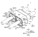
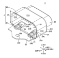
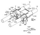
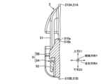
以下、本発明の実施形態を図面に基づいて説明する。図1は、本発明の実施形態に係るシールド構造1を示す斜視図である。図2は、シールド構造1を構成するシールドシェル2を示す斜視図である。図3は、シールド構造1を構成するハウジング3が電線10を保持した状態を示す斜視図である。シールド構造1は、自動車などに配索されるワイヤハーネスを構成するものであり、制御信号等を伝送する電線10から外部に漏洩する電気的なノイズ、または外部から流入される電気的なノイズを遮蔽するシールド回路を構成する。
The following describes an embodiment of the present invention with reference to the drawings. Fig. 1 is a perspective view showing a
本実施形態のシールド構造1は、図1、2に示すように、一対の電線10(電線、図1に示す)の所定位置に支持されとともに車体における金属製の取付け対象に固定されてシールド回路を形成するものであって、シールド空間20(図2に示す)を有する筒状のシールドシェル2と、一対の電線10、10を保持してシールド空間20に挿入されるハウジング3(図1に示す)と、シールドシェル2に設けられてハウジング3をシールド空間20に案内するためのシェル側案内部4(案内構造、図2に示す)と、を備える。一対の電線10、10は、それぞれ、その端部(後端部、図1の手前側の端部)に不図示の端末コネクタが接続されている。
As shown in Figures 1 and 2, the
以下では、一対の電線10、10それぞれの軸方向を「前後方向」と記し「矢印Y」で示し、一対の電線10、10、2が並ぶ方向を「左右方向」と記し「矢印X」で示し、矢印Xと矢印Yに直交するとともに、一対の分割体31A、31Bが電線10を挟む方向を「高さ方向」と記し「矢印Z」で示す場合がある。また、矢印Yのうち、電線10の一端側(図1中の奥前側)を「前方Y1」と記し、これとは反対側を「後方Y2」と記す場合がある。また、矢印Zのうち、一方を「上方Z1」、他方を「下方Z2」と記す場合がある。
In the following, the axial direction of each of the pair of
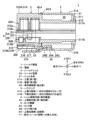
シールドシェル2は、導電性の金属板にプレス加工や曲げ加工が施されて構成されている。このシールドシェル2は、図2に示すように、シールド空間20を構成するシェル本体21と、該シェル本体21の前方Y1に連続する筒状部22と、シェル本体21の後方Y2に連続して設けられて不図示の取付け対象にボルト締結される板状の車体締結部23(延出板)と、ハウジング3に設けられた後述の係止アーム314に係止される被係止部24と、ハウジング3をシールド空間20に案内するシェル側案内部4と、を備える。
The
シェル本体21は、図2に示すように、上壁21A(第1壁)、底壁21B(第2壁)、及び一対の側壁21C、21Dを有し、前後方向Yを軸とする四角筒状に形成されてシールド空間20を構成する収容部本体210と、該収容部本体210の後端部に位置して筒状部22との隙間を埋める閉塞壁211と、を備える。
As shown in FIG. 2, the
このシェル本体21の高さ寸法(上壁21Aから底壁21Bまでの内径寸法)L0(図2に示す)は、後述のハウジング3が係合状態である際の高さ寸法より大きい寸法となるように構成され、ハウジング3が非係合状態である際の高さ寸法より小さい寸法となるように構成されている。
The height dimension (inner diameter dimension from
車体締結部23は、図2に示すように、前後方向Yおよび左右方向Xに延在する板状に構成されているとともに、シェル本体21の底壁21Bに、後述の下側案内部41を介して連続して設けられている。この車体締結部23には、不図示のボルトが挿通されるボルト挿通孔230が設けられている。
2, the vehicle
被係止部24は、図2に示すように、シェル本体21の底壁21Bに設けられているとともに、左右方向Xに間隔をあけて一対で設けられている。各被係止部24は、底壁21Bが切り欠かれて形成された切断端縁24Aを含んで、シールド空間20に向かって上方Z1に膨出する膨出部24Bと、切断端縁24Aの前方Y1に設けられた孔24Cと、を有して構成されている。切断端縁24Aは、膨出部24Bの前端縁を構成する。この膨出部24Bは、前後方向Yに連続して設けられているとともに、その後端は車体締結部23に設けられ、前端(切断端縁24A)は、後述のシェル側案内部4を構成する下側案内部41を跨いで、シェル本体21の底壁21Bに設けられている。
2, the
シェル側案内部4は、図2に示すように、上側案内部40(第1案内部)と、下側案内部41(第2案内部)と、を備える。
As shown in FIG. 2, the shell
上側案内部40は、シェル本体21の上壁21Aの後端縁に設けられているとともに、前方Y1に進むにしたがって下方Z2に向かうように傾斜する第1ガイド面を有して構成されている。換言すれば、上側案内部40は、シェル本体21の後端縁を切り欠いて構成されたテーパ形状である。この上側案内部40は、前後方向Yにおいて、下側案内部41を挟んで車体締結部23から離れた位置に設けられている。また上側案内部40は、下側案内部41によってハウジング3が押し上げられた際に、ハウジング3の後述する上側当接部60(図3に示す)に当接される位置に設けられている。
The
下側案内部41は、シェル本体21の底壁21Bと車体締結部23との間に位置する段差にあって、前方Y1に進むにしたがって、上方Z1(シールド空間20の内方)に向かうように傾斜する第2ガイド面を有して構成されている。
The
ハウジング3は、図3、4に示すように、一対の電線10、10それぞれを挿通させる一対の電線挿通部30、30(図3に示す)を有し、一対の電線10、10を挟んで保持する上側分割体31Aおよび下側分割体31B(一対の分割体)と、該上側分割体31Aおよび下側分割体31Bの左右方向Xの一方の側面に設けられたロック機構5(図4に示す)と、一対の分割体31A、31Bの左右方向Xの他方の側面に設けられて一対の分割体31A、31B同士を連結するヒンジ32(図3に示す)と、を備える。
As shown in Figs. 3 and 4, the
上側分割体31Aおよび下側分割体31Bは、それぞれがブロック状に構成されている。これらの上側分割体31Aおよび下側分割体31Bは、それぞれが上下に直交する方向(XY方向)に延在する分割面310a、310bを有し、各分割面310a、310bが接触した状態で、後述の電線挿通部30に挿通された電線10が保持されるように構成されている。
The
また各電線挿通部30は、図3に示すように、一対の分割体31A、31Bそれぞれの分割面310a、310bを、前後方向Yに延在する溝状に切り欠いて形成された一対の凹溝部30A、30Bを有して構成されている。以下では、一対の凹溝部30A、30Bのうち一方を「上側凹溝部30A」と記し、一対の凹溝部30A、30Bのうち他方を「下側凹溝部30B」と記す場合がある。上側凹溝部30Aは上側分割体31Aに設けられ、下側凹溝部30Bは下側分割体31Bに設けられている。
As shown in FIG. 3, each
上側分割体31Aは、図3に示すように、上側分割面310aに上側凹溝部30Aが形成された上側分割体本体310Aと、該上側分割体本体310Aの上側凹溝部30Aに連続しているとともに前方Y1に延出されて一対の電線10、10それぞれを支持する一対の上側電線支持部311A、311Aと、一対の上側電線支持部311A、311Aを連結する上側連結部312Aと、を備える。
As shown in FIG. 3, the
下側分割体31Bは、図3、6に示すように、下側分割面310bに下側凹溝部30Bが形成された下側分割体本体310Bと、該下側分割体本体310Bの下側凹溝部30Bに連続しているとともに上側電線支持部311Aに組み付いて、一対の電線10、10それぞれを支持する下側電線支持部311Bと、下側分割体本体310Bの下側凹溝部30Bに連続しているとともに後方Y2に延出されて一方の電線10を支持する一方側支持部313Bと、シールドシェル2の被係止部24を係止する係止アーム314(図6に示す)と、を備える。
As shown in Figures 3 and 6, the
この下側分割体本体310Bには、図1、3に示すように、シェル本体21に設けられた被係止部24を挿通させる挿通部315が設けられている。挿通部315は、図6に示すように、下側凹溝部30Bの下方Z2に位置しているとともに、下側分割体本体310Bの下面(シェル本体21の底壁21Bに接触可能な面)において前後方向Yに延在する凹溝状に形成されている。
As shown in Figs. 1 and 3, the
係止アーム314は、図6、7に示すように、下側凹溝部30Bと挿通部315との間に位置する壁部300を切り欠いて形成されているとともに前方Y1に延びて形成されたアーム本体316と、該アーム本体316の自由端に設けられて被係止部24(切断端縁24A)に係止する係止突起317と、を備えて構成されている。
As shown in Figures 6 and 7, the
ロック機構5は、図4、5に示すように、上側分割体31Aに設けられたロック部5Aと、下側分割体31Bに設けられてロック部5Aに係合するロック受け部5Bと、を備えて構成されている。
As shown in Figures 4 and 5, the
ロック部5Aは、上下方向Zに延在するとともに前後方向Yに並んで設けられた一対の延在部51、51と、該一対の延在部51、51それぞれの下端部同士を連結する連結部52と、を有してU字状に構成されている。このロック部5Aは、左右方向Xに接離可能に構成されている。またロック部5Aは、上端が上側分割体31Aの左右方向Xの一方の側面に固定され、下端が上側分割体31Aの分割面310aから下方Z2に突出して設けられている。
The
ロック受け部5Bは、下側分割体31Bの左右方向Xの一方の側面から突出する突起部から構成されている。このロック受け部5Bは、上側分割体31Aおよび下側分割体31Bが互いに近付いて、互いの分割面310a、310b同士が接触した際に、ロック部5AのU字の内側、即ち、一対の延在部51、51および連結部52の内側に位置付けられるように構成されている。本実施形態では、ロック受け部5Bが、ロック部5AのU字の内側に位置付けられた状態を、「ロック部5Aとロック受け部5Bとが係合した係合状態」と記し、係合状態では、一対の分割体31A、31Bが電線10を保持した状態が維持されるようになっている。
The
またハウジング3には、図4に示すように、シールドシェル2の上側案内部40に当接する上側当接部60(当接部)と、シールドシェル2の下側案内部41に当接する下側当接部61と、が設けられている。
As shown in FIG. 4, the
上側当接部60は、図4に示すように、上側分割体31Aの上面と前面との境界に位置する隅部に設けられているとともに、前方Y1に進むにしたがって下方Z2に向かうテーパを有して構成されている。この下側当接部61のテーパは、シールドシェル2の上側案内部40の傾斜(テーパ)と、逆のテーパとなるように構成されている。これにより上側当接部60は、ハウジング3が前方Y1に移動されるに伴って、上側案内部40に当接して摺動されるように構成されている。
As shown in FIG. 4, the
下側当接部61は、図4に示すように、下側分割体31Bの下面と前面との境界に位置する隅部に設けられているとともに、前方Y1に進むにしたがって上方Z1に向かうテーパを有して構成されている。このような下側当接部61によって、ハウジング3が前方Y1に移動されるに伴って、下側案内部41に摺動されるように構成されている。
As shown in FIG. 4, the
続いて、上述した構成のシールド構造1を組み立てる組立て手順について、図1、3~7を参照して説明する。図6、7では、電線10は省略されている。
Next, the assembly procedure for assembling the
まず、シールドシェル2を車体締結部23が後方Y2を向く格好で、その内部に一対の電線10、10を挿通させておく。そして、ハウジング3をシールドシェル2の後方Y2に位置付け、各電線10の所定位置を、ハウジング3の上側分割体31A(または下側分割体31B)の上側凹溝部30A(または下側凹溝部30B)に設置して、各電線10をテープまたは結束バンドを用いて上側分割体31A(または下側分割体31B)に固定する。
First, the pair of
そして、上側分割体31Aを下側分割体31Bに近付けるように変位(移動)させる。上側分割体31Aの変位が進んで、上側分割体31Aに設けられたロック部5Aの先端が、下側分割体31Bのロック受け部5Bに接触する。変位が進んで、ロック部5Aがロック受け部5Bに当接し、ロック部5Aが撓んでロック受け部5Bを乗り上げる。さらに変位が進んで、ロック部5Aがロック受け部5Bを乗り越えて、ロック部5Aが自然状態に復帰する。これと略同時に、上側分割体31Aおよび下側分割体31Bの各分割面310a、310b同士が互いに接触し、各電線10が各電線挿通部30に挿通されるとともに、図4、5に示すように、ロック受け部5Bが、ロック部5AのU字の内側、即ち一対の延在部51、51および連結部52の内側に位置付けられる。このようにして、ハウジング3は、ロック部5Aがロック受け部5Bに係合した係合状態となる。この係合状態では、図3に示すように、一対の分割体31A、31Bが電線10を挟み込んで保持した状態が維持されている。
Then, the upper
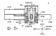
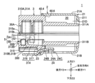
この後、シールドシェル2に対して、(係合状態の)ハウジング3を前方Y1に移動させる。移動が進んで、ハウジング3の下側当接部61がシールドシェル2の下側案内部41に当接する。さらに移動が進んで、図7に示すように、下側当接部61が下側案内部41の第2ガイド面の傾斜に摺動されて、下側案内部41を乗り上げて、ハウジング3はシールドシェル2のシールド空間20に挿入される。さらに移動が進んで、ハウジング3の係止アーム314が、シールドシェル2の被係止部24を係止する。これにより、ハウジング3はシールドシェル2に対して抜止めされる。このようにしてシールドシェル2の組立てが完了する。
Then, the housing 3 (in an engaged state) is moved forward Y1 relative to the shielded
続いて、ハウジング3が非係合状態、即ち、ロック受け部5Bが、ロック部5AのU字の内側、即ち一対の延在部51、51および連結部52の内側に位置付けられていない状態(非係合状態)で、シールドシェル2のシールド空間20に挿入された場合について、図6、7を参照して説明する。
Next, the case where the
シールドシェル2に対して、(非係合状態の)ハウジング3を前方Y1に移動させる。移動が進んで、ハウジング3の下側当接部61がシールドシェル2の下側案内部41に当接する。さらに移動が進んで、図6に示すように、下側当接部61が下側案内部41の傾斜に摺動されて、下側案内部41を乗り上げる。これと略同時に、ハウジング3の上側当接部60がシールドシェル2の上側案内部40に当接する。さらに移動が進んで、上側当接部60が上側案内部40の第1ガイド面の傾斜に摺動されて、上側分割体31Aが下側分割体31Bに押し付けられる。これにより、ロック部5Aがロック受け部5Bに近付いて、ロック受け部5Bが、ロック部5AのU字の内側、即ち一対の延在部51、51および連結部52の内側に位置付けられる。このようにして、ハウジング3は、ロック部5Aがロック受け部5Bに係合した係合状態となり、図7に示すように、シールド空間20の内部への挿入が許容されることとなる。さらに移動が進んで、ハウジング3の係止アーム314が、シールドシェル2の被係止部24を係止する。これにより、ハウジング3はシールドシェル2に対して抜止めされる。このようにしてシールド構造1の組立てが完了する。
The housing 3 (in a non-engaged state) is moved forward Y1 relative to the
この後、シールド構造1は、車体締結部23にボルト締結される。このようにして制御信号等を伝送する電線10から外部に漏洩する電気的なノイズ、または外部から流入される電気的なノイズを遮蔽するシールド回路が構成される。
The
上述した実施形態によれば、ハウジング3がシールド空間20に挿入されるに伴って、ハウジング3はシェル側案内部4(案内構造)に案内されることにより、一対の分割体31A、31B同士が互いに近付いて、ロック部5Aおよびロック受け部5Bが係合するように構成されている。これによれば、従来技術の如く、治具を用意するための費用や一対の分割体31A、31Bが係合状態であるかを確認(検知)するための作業を省略することができるから、製造コストの低減を図ることができる。
According to the above-described embodiment, as the
また、シェル側案内部4(案内構造)は、上側案内部40(第1案内部)を有し、上側案内部40は、上壁21A(第1壁)に設けられているとともに、(ハウジング3がシールド空間20に挿入される挿入方向)前方Y1に進むにしたがって、底壁21B(第2壁)に向けて突出するように傾斜した第1ガイド面を有して構成されている。これによれば、ハウジング3が非係合状態である場合には、ハウジング3は上側案内部40を構成する第1ガイド面の傾斜に摺動され、一対の分割体31A、31Bのうち一方が他方に押し付けられることにより、一対の分割体31A、31B同士が互いに近付いて、ロック部5Aがロック受け部5Bに係合した係合状態でシールド空間20に挿入される構成を実現できる。
The shell-side guide section 4 (guide structure) has an upper guide section 40 (first guide section), which is provided on the
また、シェル側案内部4(案内構造)は、下側案内部41(第2案内部)を有し、下側案内部41は、底壁21B(第2壁)と車体締結部23(延出板)との間に設けられているとともに、前方Y1(ハウジング3がシールド空間20に挿入される挿入方向)に進むにしたがって、上壁21A(第1壁)に向けて突出するように傾斜した第2ガイド面を有して構成されている。これによれば、ハウジング3が非係合状態である場合には、ハウジング3は下側案内部41を構成する第2ガイド面の傾斜に摺動され、第2ガイド面を乗り上げることにより、一対の分割体31A、31Bのうち他方が一方に押し付けられることにより、一対の分割体31A、31B同士が互いに近付いて、ロック部5Aがロック受け部5Bに係合した係合状態でシールド空間20に挿入される構成を実現できる。
The shell-side guide section 4 (guide structure) has a lower guide section 41 (second guide section), which is provided between the
また、ハウジング3は、上側分割体31A(一対の分割体31A、31Bのうち一方)に、上側案内部40(第1案内部)に当接可能な上側当接部60(当接部)を有し、上側案内部40は、下側案内部41(第2案内部)を挟んで車体締結部23(延出板)とは離れた側に設けられ、上側案内部40は、ハウジング3が下側案内部41に案内された際に、上側当接部60が当接される位置に設けられている。これによれば、ハウジング3がシールドシェル2の下側案内部41および上側案内部40に当接するタイミングがずらされることとなり、非係合状態であったとしても、ハウジング3は、小さな力でスムーズに、シールド空間20に挿入される構成を実現できる。
The
また、シェル本体21において一対の分割体31A、31Bが電線10を挟む方向の内寸L0は、ハウジング3においてロック部5Aとロック受け部5Bとが係合していない非係合状態より小さく、ロック部5Aとロック受け部5Bとが係合した係合状態より大きくなるように構成されている。これによれば、ハウジング3が非係合状態でシールド空間20に挿入されることを阻止することができる。
The inner dimension L0 of the
その他、本発明を実施するための最良の構成、方法などは、以上の記載で開示されているが、本発明は、これに限定されるものではない。すなわち、本発明は、主に特定の実施形態に関して特に図示され、且つ、説明されているが、本発明の技術的思想および目的の範囲から逸脱することなく、以上述べた実施形態に対し、形状、材質、数量、その他の詳細な構成において、当業者が様々な変形を加えることができるものである。従って、上記に開示した形状、材質などを限定した記載は、本発明の理解を容易にするために例示的に記載したものであり、本発明を限定するものではないから、それらの形状、材質などの限定の一部、もしくは全部の限定を外した部材の名称での記載は、本発明に含まれるものである。 Although the best configurations and methods for implementing the present invention have been disclosed above, the present invention is not limited thereto. That is, the present invention has been mainly illustrated and described with reference to specific embodiments, but those skilled in the art can make various modifications to the above-described embodiments in terms of shape, material, quantity, and other detailed configurations without departing from the scope of the technical idea and purpose of the present invention. Therefore, the descriptions limiting the shapes, materials, etc. disclosed above are provided as examples to facilitate understanding of the present invention, and do not limit the present invention. Therefore, descriptions of the names of components that have some or all of the limitations on the shapes, materials, etc. removed are included in the present invention.
1 シールド構造
10 電線
2 シールドシェル
20 シールド空間
21 シェル本体
21A 上壁(第1壁)
21B 底壁(第2壁)
23 車体締結部(延出板)
3 ハウジング
31A 上側分割体(一対の分割体のうち一方)
31B 下側分割体(一対の分割体のうち他方)
4 シェル側案内部(案内構造)
40 上側案内部(第1案内部)
41 下側案内部(第2案内部)
5 ロック機構
5A ロック部
5B ロック受け部
60 上側当接部(当接部)
Y1 前方(シールド空間への挿入方向)
REFERENCE SIGNS
21B Bottom wall (second wall)
23 Vehicle body fastening portion (extension plate)
3
31B Lower division body (the other of the pair of division bodies)
4. Shell side guide section (guide structure)
40 Upper guide part (first guide part)
41 Lower guide part (second guide part)
5
Y1: Front (insertion direction into shielded space)
Claims (5)
シールド空間を有する筒状のシールドシェルと、
前記電線を保持して前記シールド空間に挿入されるハウジングと、を備え、
前記シールドシェルは、前記ハウジングを前記シールド空間に案内する案内構造を有し、
前記ハウジングは、前記電線を挟んで保持する一対の分割体と、該一対の分割体が前記電線を保持した状態を維持するためのロック機構と、を有し、
前記ロック機構は、前記一対の分割体のうち一方に設けられたロック部と、他方に設けられて前記ロック部に係合可能なロック受け部と、を有し、
前記ハウジングが前記シールド空間に挿入されるに伴って、前記ハウジングは前記案内構造に案内されることにより、前記一対の分割体同士が互いに近付いて、前記ロック部および前記ロック受け部が係合するように構成されていることを特徴とするシールド構造。 A shielding structure supported in a predetermined position on an electric wire,
A cylindrical shield shell having a shield space;
a housing that holds the electric wire and is inserted into the shielded space,
the shield shell has a guide structure that guides the housing into the shielded space,
the housing has a pair of divided bodies that sandwich and hold the electric wire, and a locking mechanism that maintains a state in which the pair of divided bodies hold the electric wire,
the lock mechanism includes a lock portion provided on one of the pair of divided bodies and a lock receiving portion provided on the other of the pair of divided bodies and capable of engaging with the lock portion,
A shield structure characterized in that, as the housing is inserted into the shielded space, the housing is guided by the guide structure, causing the pair of divided bodies to approach each other and engage with the locking portion and the lock receiving portion.
前記シールドシェルは、前記シールド空間を構成する筒状のシェル本体と、該シェル本体から離れる方向に延出された延出板と、を備え、
前記シェル本体は、前記一対の分割体が前記電線を挟む方向に対向する第1壁および第2壁を有し、
前記延出板は、前記第2壁に連続して設けられ、
前記第1案内部は、前記第1壁に設けられているとともに、前記ハウジングが前記シールド空間に挿入される挿入方向に進むにしたがって、前記第2壁に向けて突出するように傾斜した第1ガイド面を有して構成されていることを特徴とする請求項1に記載のシールド構造。 The guide structure has a first guide portion,
The shield shell includes a cylindrical shell main body that defines the shielded space, and an extension plate that extends in a direction away from the shell main body,
The shell body has a first wall and a second wall that face each other in a direction in which the pair of divided bodies sandwich the electric wire,
The extension plate is provided continuously with the second wall,
2. The shield structure according to claim 1, characterized in that the first guide portion is provided on the first wall and has a first guide surface that is inclined so as to protrude toward the second wall as the housing progresses in an insertion direction in which it is inserted into the shielded space.
前記第2案内部は、前記第2壁と前記延出板との間に設けられているとともに、前記ハウジングが前記シールド空間に挿入される挿入方向に進むにしたがって、前記第1壁に向けて突出するように傾斜した第2ガイド面を有して構成されていることを特徴とする請求項2に記載のシールド構造。 The guide structure has a second guide portion,
The shield structure described in claim 2, characterized in that the second guide portion is provided between the second wall and the extension plate, and is configured to have a second guide surface that is inclined so as to protrude toward the first wall as the housing progresses in an insertion direction in which it is inserted into the shielded space.
前記第1案内部は、前記第2案内部を挟んで前記延出板とは離れた側に設けられ、
前記第1案内部は、前記ハウジングが前記第2案内部に案内された際に、前記当接部が当接される位置に設けられていることを特徴とする請求項3に記載のシールド構造。 the housing has an abutment portion in one of the pair of divided bodies that is abuttable against the first guide portion,
The first guide portion is provided on a side away from the extension plate with the second guide portion interposed therebetween,
4. The shield structure according to claim 3, wherein the first guide portion is provided at a position where the abutment portion abuts against the first guide portion when the housing is guided by the second guide portion.
3. The shield structure according to claim 2, wherein an inner dimension of the pair of divided bodies in the shell main body in a direction in which the pair of divided bodies sandwich the electric wire is smaller than an inner dimension of a disengaged state in which the locking portion and the lock receiving portion are not engaged in the housing, and is larger than an inner dimension of a engaged state in which the locking portion and the lock receiving portion are engaged.
Priority Applications (3)
| Application Number | Priority Date | Filing Date | Title |
|---|---|---|---|
| JP2023148447A JP7815188B2 (en) | 2023-09-13 | Shield structure | |
| DE102024122836.9A DE102024122836A1 (en) | 2023-09-13 | 2024-08-09 | Shielding structure |
| FR2408886A FR3152929A1 (en) | 2023-09-13 | 2024-08-13 | Protective structure |
Applications Claiming Priority (1)
| Application Number | Priority Date | Filing Date | Title |
|---|---|---|---|
| JP2023148447A JP7815188B2 (en) | 2023-09-13 | Shield structure |
Publications (2)
| Publication Number | Publication Date |
|---|---|
| JP2025041258A true JP2025041258A (en) | 2025-03-26 |
| JP7815188B2 JP7815188B2 (en) | 2026-02-17 |
Family
ID=
Citations (2)
| Publication number | Priority date | Publication date | Assignee | Title |
|---|---|---|---|---|
| JP2014154359A (en) * | 2013-02-08 | 2014-08-25 | Yazaki Corp | Connector |
| JP2017168421A (en) * | 2016-03-10 | 2017-09-21 | 日立金属株式会社 | Wire harness |
Patent Citations (3)
| Publication number | Priority date | Publication date | Assignee | Title |
|---|---|---|---|---|
| JP2014154359A (en) * | 2013-02-08 | 2014-08-25 | Yazaki Corp | Connector |
| JP2017168421A (en) * | 2016-03-10 | 2017-09-21 | 日立金属株式会社 | Wire harness |
| JP2020053392A (en) * | 2016-03-10 | 2020-04-02 | 日立金属株式会社 | Wire harness |
Also Published As
| Publication number | Publication date |
|---|---|
| DE102024122836A1 (en) | 2025-03-13 |
| FR3152929A1 (en) | 2025-03-14 |
Similar Documents
| Publication | Publication Date | Title |
|---|---|---|
| JP3479773B2 (en) | Flat cable connector | |
| US9246260B2 (en) | Electrical connector | |
| EP0967692B1 (en) | Connector and connector attachment structure | |
| JP2013110067A (en) | Connector and method of manufacturing the same | |
| JP2025062114A (en) | Shield Terminal | |
| CN110462940B (en) | Connector | |
| JP2025041258A (en) | Shield structure | |
| JP7444131B2 (en) | connector | |
| JP7815188B2 (en) | Shield structure | |
| US7658640B2 (en) | Cable connector, method of connecting a cable connector and a cable | |
| JP6286012B1 (en) | Control circuit device for vehicle automatic transmission and connector for vehicle | |
| JP2001110466A (en) | ID connector | |
| US11637396B2 (en) | Electrical connector assembly with a releasable locking structure | |
| JP2024157795A (en) | Connector manufacturing equipment | |
| US10096925B2 (en) | Connector | |
| JP2025062384A (en) | Shield structure | |
| US12472889B2 (en) | Electric wire holder | |
| US20250323440A1 (en) | Electrical connector for flat conductor | |
| JP2017117625A (en) | Connector and self-alignment connector | |
| JPS61161679A (en) | Electric connector for receptacle | |
| CN115207851B (en) | Electrical junction box, manufacturing method of electrical junction box, and wiring harness | |
| KR101175571B1 (en) | Electric connector | |
| JP3506361B2 (en) | Assembly connection structure of electrical unit | |
| US20250323439A1 (en) | Electrical connector for flat conductor | |
| JP2025170875A (en) | connector |
Legal Events
| Date | Code | Title | Description |
|---|---|---|---|
| A621 | Written request for application examination |
Free format text: JAPANESE INTERMEDIATE CODE: A621 Effective date: 20241115 |
|
| A977 | Report on retrieval |
Free format text: JAPANESE INTERMEDIATE CODE: A971007 Effective date: 20250930 |
|
| A131 | Notification of reasons for refusal |
Free format text: JAPANESE INTERMEDIATE CODE: A131 Effective date: 20251028 |
|
| A521 | Request for written amendment filed |
Free format text: JAPANESE INTERMEDIATE CODE: A523 Effective date: 20251211 |
|
| A01 | Written decision to grant a patent or to grant a registration (utility model) |
Free format text: JAPANESE INTERMEDIATE CODE: A01 Effective date: 20260203 |
|
| A61 | First payment of annual fees (during grant procedure) |
Free format text: JAPANESE INTERMEDIATE CODE: A61 Effective date: 20260204 |