JP2025041255A - Saddle type vehicle - Google Patents
Saddle type vehicle Download PDFInfo
- Publication number
- JP2025041255A JP2025041255A JP2023148441A JP2023148441A JP2025041255A JP 2025041255 A JP2025041255 A JP 2025041255A JP 2023148441 A JP2023148441 A JP 2023148441A JP 2023148441 A JP2023148441 A JP 2023148441A JP 2025041255 A JP2025041255 A JP 2025041255A
- Authority
- JP
- Japan
- Prior art keywords
- shroud
- wing
- saddle
- vehicle
- vehicle body
- Prior art date
- Legal status (The legal status is an assumption and is not a legal conclusion. Google has not performed a legal analysis and makes no representation as to the accuracy of the status listed.)
- Granted
Links
Images



Classifications
-
- B—PERFORMING OPERATIONS; TRANSPORTING
- B62—LAND VEHICLES FOR TRAVELLING OTHERWISE THAN ON RAILS
- B62J—CYCLE SADDLES OR SEATS; AUXILIARY DEVICES OR ACCESSORIES SPECIALLY ADAPTED TO CYCLES AND NOT OTHERWISE PROVIDED FOR, e.g. ARTICLE CARRIERS OR CYCLE PROTECTORS
- B62J17/00—Weather guards for riders; Fairings or stream-lining parts not otherwise provided for
- B62J17/10—Ventilation or air guiding devices forming part of fairings
-
- B—PERFORMING OPERATIONS; TRANSPORTING
- B62—LAND VEHICLES FOR TRAVELLING OTHERWISE THAN ON RAILS
- B62J—CYCLE SADDLES OR SEATS; AUXILIARY DEVICES OR ACCESSORIES SPECIALLY ADAPTED TO CYCLES AND NOT OTHERWISE PROVIDED FOR, e.g. ARTICLE CARRIERS OR CYCLE PROTECTORS
- B62J43/00—Arrangements of batteries
- B62J43/10—Arrangements of batteries for propulsion
- B62J43/16—Arrangements of batteries for propulsion on motorcycles or the like
Landscapes
- Engineering & Computer Science (AREA)
- Mechanical Engineering (AREA)
- Automatic Cycles, And Cycles In General (AREA)
Abstract
Description
本発明は、鞍乗り型車両に関する。 The present invention relates to a saddle-type vehicle.
従来、ウィングを備えた鞍乗り型車両が知られている(例えば、特許文献1参照)。特許文献1に記載の鞍乗り型車両では、カウルの車幅方向外端部に、ウィングとしての翼部を左右一対設けており、翼部によりダウンフォースを得ている。特許文献1では、左右の翼部の間には、吸気用の吸気口が形成されている。特許文献1の吸気口は、燃料タンクよりも前方に形成されており、車体の前部に形成されている。
Conventionally, saddle-type vehicles equipped with wings are known (see, for example, Patent Document 1). In the saddle-type vehicle described in
ところで、特許文献1では、吸入口としての吸気口がカウルの前面に設けられているが、鞍乗り型車両によっては、吸入口に走行風が流入し易いと吸気量が過剰になる可能性がある。このため、吸入口が車体の前部に形成される場合であっても、走行風が吸入口に流入する量を調整すること求められていた。また、一般的な課題として、ライダーの疲労軽減のためには、走行風をライダーに当たらないようにすることが望ましい。
本発明は、上述した事情に鑑みてなされたものであり、吸入口が車体の前部に設けられる場合でも、必要十分な吸気量を得られ易く、ライダーに走行風が当たることが抑制された鞍乗り型車両を提供することを目的とする。
In
The present invention has been made in consideration of the above-mentioned circumstances, and aims to provide a saddle-type vehicle that can easily obtain a necessary and sufficient intake volume even when the intake port is provided at the front of the vehicle body, and that prevents the rider from being exposed to the wind caused by driving.
鞍乗り型車両は、エネルギー貯蔵部と、シュラウドウィング及びシュラウドインテークと、を備えた鞍乗り型車両において、吸入口が設けられ、前記エネルギー貯蔵部の左右側方に配置されて走行風をシートの下方に導風する前記シュラウドインテークと、前記シュラウドインテークの前方に配置され、シュラウドウィング下面により走行風を前記吸入口に導き、シュラウドウィング上面により走行風を車体の側方に流す前記シュラウドウィングと、前記シュラウドウィングは、シュラウドウィング側部よりも車体幅方向内側にウィング本体部を備え、前記ウィング本体部は、車体前後方向前側かつ車体幅方向内側に設けられた第1尖り部と、車体前後方向後側かつ車体幅方向外側に設けられた第2尖り部と、を備え、車体側面視で前方から、前記ウィング本体部、前記吸入口、前記エネルギー貯蔵部の順に配置されることを特徴とする。 The saddle-ride type vehicle is a saddle-ride type vehicle including an energy storage unit, a shroud wing, and a shroud intake, the shroud intakes being provided with intake ports and arranged on the left and right sides of the energy storage unit to guide the traveling wind below the seat, the shroud wing being arranged in front of the shroud intake and guiding the traveling wind to the intake port by the lower surface of the shroud wing and directing the traveling wind to the side of the vehicle body by the upper surface of the shroud wing, the shroud wing having a wing main body part on the inner side in the vehicle body width direction than the shroud wing side part, the wing main body part having a first pointed part arranged on the front side in the vehicle body fore-and-aft direction and on the inner side in the vehicle body width direction, and a second pointed part arranged on the rear side in the vehicle body fore-and-aft direction and on the outer side in the vehicle body width direction, the wing main body part, the intake port, and the energy storage unit being arranged in this order from the front when viewed from the side of the vehicle body.
吸入口が車体の前部に設けられる場合でも、必要十分な吸気量を得られ易く、ライダーに走行風が当たることが抑制された鞍乗り型車両を提供することができる。 Even if the intake port is located at the front of the vehicle body, it is easy to obtain a sufficient amount of intake air, and it is possible to provide a saddle-type vehicle in which the rider is prevented from being exposed to the wind while riding.
以下、図面を参照して本発明の実施の形態について説明する。なお、説明中、前後左右および上下といった方向の記載は、特に記載がなければ車体に対する方向と同一とする。また、各図に示す符号FRは車体前方を示し、符号UPは車体上方を示し、符号LHは車体左方を示す。 Below, an embodiment of the present invention will be described with reference to the drawings. In the description, directions such as front, back, left, right, and up and down are the same as directions relative to the vehicle body unless otherwise specified. In addition, the symbol FR in each figure indicates the front of the vehicle body, the symbol UP indicates the upper part of the vehicle body, and the symbol LH indicates the left side of the vehicle body.
[実施の形態]
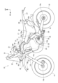
図1は、本発明の実施の形態に係る鞍乗り型車両10の側面図である。
鞍乗り型車両10は、車体フレーム11と、車体フレーム11に支持されるパワーユニット12と、前輪13を操舵自在に支持するフロントフォーク14と、後輪15を支持するスイングアーム16と、乗員用のシート17とを備える車両である。
鞍乗り型車両10は、乗員がシート17に跨るようにして着座する車両である。シート17は、車体フレーム11の後部の上方に設けられる。
[Embodiment]
FIG. 1 is a side view of a saddle-
The saddle-
The saddle-
車体フレーム11は、車体フレーム11の前端部に設けられるヘッドパイプ18と、ヘッドパイプ18の後方に位置するフロントフレーム19と、フロントフレーム19の後方に位置するリアフレーム20とを備える。フロントフレーム19の前端部は、ヘッドパイプ18に接続される。
シート17は、リアフレーム20に支持される。
The
The
フロントフォーク14は、ヘッドパイプ18によって左右に操舵自在に支持される。前輪13は、フロントフォーク14の下端部に設けられる車軸13aに支持される。乗員が把持する操舵用のハンドル21は、フロントフォーク14の上端部に取り付けられる。
The
スイングアーム16は、車体フレーム11に支持されるピボット軸22に支持される。ピボット軸22は、車幅方向に水平に延びる軸である。スイングアーム16の前端部には、ピボット軸22が挿通される。スイングアーム16は、ピボット軸22を中心に上下に揺動する。
後輪15は、スイングアーム16の後端部に設けられる車軸15aに支持される。
The
The
パワーユニット12は、前輪13と後輪15との間に配置され、車体フレーム11に支持される。
パワーユニット12は、内燃機関である。パワーユニット12は、クランクケース23と、往復運動するピストンを収容するシリンダー部24とを備える。シリンダー部24の排気ポートには、排気装置25が接続される。
パワーユニット12の出力は、パワーユニット12と後輪15とを接続する駆動力伝達部材によって後輪15に伝達される。
The
The
The output of the
また、鞍乗り型車両10は、前輪13を上方から覆うフロントフェンダー26と、後輪15を上方から覆うリアフェンダー27と、乗員が足を載せるステップ28と、パワーユニット12が使用する燃料を蓄える燃料タンク29とを備える。
フロントフェンダー26は、フロントフォーク14に取り付けられる。リアフェンダー27及びステップ28は、シート17よりも下方に設けられる。燃料タンク29は、車体フレーム11に支持される。
The saddle-
The
本実施の形態では、フロントフレーム19は、左右一対のメインフレーム部19aと、メインフレーム部19aの後端から下方に湾曲しながら延びる左右一対のピボットフレーム部19bと、ヘッドパイプ18から下方に延びるダウンフレーム部19cと、ダウンフレーム部19cの下端から後方に延びてピボットフレーム部19bの下端に接続される左右一対のロアフレーム部19dと、を有する。
本実施の形態では、フロントフレーム19は、金属製である。
In this embodiment, the
In this embodiment, the
リアフレーム20は、側面視で前後方向に帯状に延びる左右一対のシートフレーム部20aと、ピボットフレーム部19bからシートフレーム部20aに延びるサブフレーム部20bと、を有する。シートフレーム部20aは、メインフレーム部19aの車幅方向外側に位置する。リアフレーム20は、シートフレーム部20aがピボットフレーム部19bの上端部に接続される。また、リアフレーム20は、サブフレーム部20bがピボットフレーム部19bの上下中間部に接続される。
本実施の形態では、リアフレーム20は、CFRP(Carbon Fiber Reinforced Plastics)製である。
The
In this embodiment, the
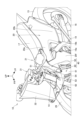
図2は、鞍乗り型車両10の左上方からの斜視図である。図3は、鞍乗り型車両10の要部を示す斜視図である。図4は、図3からタンクシュラウド40を省略した図である。
鞍乗り型車両10は、メータユニット31を有する。メータユニット31は、ハンドル21の前方に支持される。メータユニット31は、前方からフロントスクリーン32で覆われる。
Fig. 2 is a perspective view from the upper left of the
The
図4に示すように、左右一対のメインフレーム部19aには、左右一対のフロントタンク(エネルギー貯蔵部)29fが支持される。フロントタンク29fは、左右対称に形成される。フロントタンク29fは、上下方向に長い容器状である。フロントタンク29fは、メインフレーム部19aの前端部において、メインフレーム部19aの上部から車幅方向外側にわたって配置される。フロントタンク29fは、メインフレーム部19aの上方から下方に延びる。フロントタンク29fは、車幅方向内側のタンク上部29f1と、タンク上部29f1の下部から下方に延びるタンク下部29f2と、を有する。タンク下部29f2は、タンク上部29f1よりも車幅方向外側に膨出している。よって、タンク上部29f1の外側面とタンク下部29f2の上面とにより、車幅方向内側に凹むような凹部29f3が形成される。凹部29f3は、前後方向に延びる。
As shown in FIG. 4, a pair of left and right front tanks (energy storage units) 29f are supported on the pair of left and right
フロントタンク29fの後方には、左右一対のリアタンク29rが設けられる。リアタンク29rは、リアフレーム20に支持される。詳細には、リアタンク29rは、シートフレーム部20aおよびサブフレーム部20bに支持される。リアタンク29rは、燃料配管を介してフロントタンク29fに接続される。
本実施の形態では、フロントタンク29fとリアタンク29rとにより、燃料タンク29が構成される。
A pair of left and right
In the present embodiment, the
図5は、シート17の周辺部を示す鞍乗り型車両10の後上方からの斜視図である。
フロントタンク29fとリアタンク29rとの間には、エアクリーナボックス34が配置される。エアクリーナボックス34は、シート17の下方に配置される。よって、シート17が鞍乗り型車両10から取り外されると、エアクリーナボックス34が左右一対のシートフレーム部20aの間から上方に露出する。エアクリーナボックス34は、車幅方向中央部に吸気口34aを備える。吸気口34aは、後方に開口する。エアクリーナボックス34は、シート17の下方の吸気スペースSから吸気する。吸気スペースSは、左右一対のシートフレーム部20aに挟まれた空間である。
FIG. 5 is a perspective view of the saddle-
An air
図6は、左側のタンクシュラウド40の左前方からの斜視図である。図7は、左側のタンクシュラウド40の左後方からの斜視図である。図8は、左側のタンクシュラウド40を車幅方向外側から見た側面図である。図9は、左側のタンクシュラウド40を車幅方向内側から見た側面図である。図10は、左側のタンクシュラウド40の平面図である。図11は、左側のタンクシュラウド40の底面図である。図12は、左側のタンクシュラウド40の正面図である。
左右のフロントタンク29fの車幅方向外側には、それぞれのタンクシュラウド40が設けられる。
Fig. 6 is a perspective view of the
Tank shrouds 40 are provided on the outer sides of the left and right
タンクシュラウド40は、フロントタンク29fの車幅方向外側に配置されるシュラウドインテーク50と、シュラウドインテーク50の前方に配置されるシュラウドウィング60と、を有する。
シュラウドインテーク50は、フロントタンク29fを車幅方向外側から覆う。シュラウドインテーク50は、車体外面を構成するアウターシュラウド部51と、アウターシュラウド部51の車幅方向内側に接続されるインナーシュラウド部52と、を備える。
The
The
アウターシュラウド部51は、前後方向に延びる。アウターシュラウド部51は、側面視で円弧状の接続部51aを有する。アウターシュラウド部51は、車幅方向内側に湾曲する上部51bを有する。アウターシュラウド部51は、タンク下部29f2の上方に配置されタンク上部29f1を車幅方向外側から覆う。すなわち、アウターシュラウド部51は、凹部29f3を車幅方向外側から覆うように支持される。これにより、フロントタンク29fの側面とアウターシュラウド部51により前後方向に延びるダクト部S1(図5参照)が形成される。ダクト部S1は吸気スペースSに連通する。アウターシュラウド部51の後部は、シートフレーム部20aに沿ってシートフレーム部20aの前端部まで延びる(図1参照)。
The
アウターシュラウド部51の前端部には、車幅方向内側からインナーシュラウド部52が接続される。インナーシュラウド部52は、アウターシュラウド部51の上部51bおよび下部に接続される。インナーシュラウド部52は、アウターシュラウド部51に対向して接続される。これにより、アウターシュラウド部51とインナーシュラウド部52との間には、前後方向に延びる筒状のダクト53(図6参照)を形成される。アウターシュラウド部51およびインナーシュラウド部52の前縁の囲み形状により、ダクト53の入口としての吸入口54が形成される。インナーシュラウド部52の後端には、車幅方向内側に屈曲した固定部52aが形成される。固定部52aは、フロントタンク29fのタンク上部29f1の前面に固定される。これにより、ダクト53が、アウターシュラウド部51とフロントタンク29fの凹部29f3とにより形成されたダクト部S1に連通する。
The
シュラウドインテーク50の前側には、シュラウドウィング60が接続される。シュラウドウィング60は、上下方向に延びるシュラウド側面部(シュラウドウィング側部)61と、シュラウド側面部61の前端に形成されたウィング本体部62と、を有する。
シュラウド側面部61には、後縁から前方に円弧状に凹んだ接続部61aが形成される。接続部61aには、シュラウドインテーク50の接続部51aが進入した状態でシュラウドインテーク50と接続される。接続部61aの下方には、上下方向に延びるスリット孔61bが形成される。
A
A
シュラウド側面部61の上部前端には、車幅方向内側に湾曲したように形成されたウィング本体部62が支持される。ウィング本体部62は、シュラウド側面部61に対して後退翼形状に形成される。すなわち、シュラウド側面部61を機体本体と見た場合に、ウィング本体部62は、機体本体に対する後退翼形状である。換言すれば、ウィング本体部62とシュラウド側面部61との間には、前方に進むに連れて先細る切り欠き63が形成される。ウィング本体部62は、シュラウド側面部61よりも車幅方向内側に位置する。ウィング本体部62は、フロントフォーク14のフォークチューブ14aよりも前側に配置される。ウィング本体部62は、フォークチューブ14aと一部が正面視で重なる(図14参照)。
A
ウィング本体部62は、上面(シュラウドウィング上面)62aと下面(シュラウドウィング下面)62bとを有し厚みが略一定の略板状である。ウィング本体部62は、上面62aに沿う走行風を鞍乗り型車両10の側方の一例としてのライダーR(図16参照)の側方に流すように上面62aが形成されると共に、下面62bに沿う走行風を吸入口54に導くように下面62bが形成される。
The
本実施の形態では、ウィング本体部62は、車体前後方向前側かつ車体幅方向内側に、前内尖り部(第1尖り部)62cを有する。前内尖り部62cは、車体前後方向前側かつ車体幅方向内側に進むに連れて先細るように形成される。また、ウィング本体部62は、車体前後方向後側かつ車体幅方向外側に、後外尖り部(第2尖り部)62dを有する。後外尖り部62dは、車体前後方向後側かつ車体幅方向外側に進むに連れて先細っている。換言すれば、後外尖り部62dにより、シュラウド側面部61との間に切り欠き63が形成される。
In this embodiment, the wing
ウィング本体部62は、車体後方に向けて上方に傾斜している(図8、図12参照)。また、ウィング本体部62は、車体幅方向内側に向けて上方に傾斜している(図6~図8、図10、図12参照)。本実施の形態では、ウィング本体部62は、連続的に湾曲して傾斜している。換言すれば、本実施の形態では、ウィング本体部62は、滑らかに湾曲して傾斜している。ウィング本体部62では、前内尖り部62cから後外尖り部62dに向けて、水平面に対して緩斜面62eから急斜面62fに角度が変わる。より具体的には、図6~図12などの各図において、前内尖り部62cと後外尖り部62dとを結ぶ補助線を破線で示す。補助線は、各図で便宜的に直線状に示す。補助線に沿って前内尖り部62cから後外尖り部62dに進むに連れて、緩斜面62eから急斜面62fに角度が変わる。
The
本実施の形態では、シュラウドインテーク50はCFRP製である。シュラウドウィング60は、PP(polypropylene)製である。シュラウドウィング60では、シュラウド側面部61に対してウィング本体部62が片持ち形状で支持される。ここで、シュラウドウィング60をPP製にすることにより、シュラウドウィング60が地面などと接触した際に、シュラウドウィング60を曲げ易くできて衝撃を吸収し易く、割れ難くすることができる。
In this embodiment, the
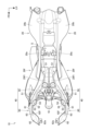
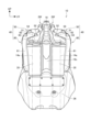
図13は、鞍乗り型車両10の要部の平面図である。図14は、鞍乗り型車両10の要部の正面図である。図15は、タンクシュラウド40の周辺を示す図1の拡大図である。
タンクシュラウド40は、フロントタンク29fの側方に取り付けられる。このとき、前方から、ウィング本体部62、吸入口54、フロントタンク29fの順に配置される。吸入口54は、前方に開口する。吸入口54は、車体側面視でヘッドパイプ18と重なる(図15参照)。吸入口54は、フォークチューブ14aよりも車幅方向外側に位置する(図14参照)。また、シュラウドウィング60のウィング本体部62は、車体正面視で吸入口54と重なる(図14参照)。詳細には、ウィング本体部62は、車体正面視で吸入口54の下部と重なり、上部とは重ならない。ウィング本体部62は、図15に示すように、フロントフェンダー26よりも上方に位置する。すなわち、ウィング本体部62は、フロントフェンダー26の上端を通過する水平面H1よりも上方に位置する。吸入口54の上端は、ウィング本体部62よりも上方に位置する。ウィング本体部62および吸入口54は、フロントスクリーン32よりも下方に配置される。すなわち、ウィング本体部62および吸入口54は、フロントスクリーン32の下端を通過する水平面H2よりも下方に配置される。
Fig. 13 is a plan view of a main part of the
The
また、図15に示すように、車体側面視で、ウィング本体部62の後端の水平面H1に対する角度θ1と、ヘッドパイプ18の軸線の水平面H2に対する角度θ2とが、略平行になるように設定される。また、車体側面視で、前内尖り部62cと後外尖り部62dとを結ぶ補助線の水平面H1に対する角度θ3は、ヘッドパイプ18が水平面H2に対して成す角度θ2よりも小さい。なお、角度θ1~θ3は、鋭角である。これにより、ウィング本体部62は、より精度よく、下面62bにより走行風を吸入口54に導くと共に、上面62aにより走行風を、車体フレーム11等で構成される車体の側方に流すことができる。
As shown in FIG. 15, the angle θ1 of the rear end of the wing
左右のタンクシュラウド40の間には、図14に示すように、左右一対のラジエータ35が配置される。ラジエータ35の下方には、エンジンガード36が配置される。エンジンガード36は、パワーユニット12を前方から覆う。本実施の形態では、エンジンガード36はCFRP製である。
As shown in FIG. 14, a pair of left and
図16は、本実施の形態の作用説明図である。
鞍乗り型車両10が走行すると、矢印A1、B1で示すように前方からシュラウドウィング60のウィング本体部62に向けて走行風が流れる。ウィング本体部62の上面62aに沿って流れる走行風は、矢印A2で示すように、上面62aにより、車体の側方に向けて案内され、矢印A3で示すように、ライダーRの側方を流れ易くなっている。よって、ライダーRが走行風から抵抗を受け難くなっており、ライダーRの疲労が蓄積し難くなっている。
FIG. 16 is a diagram illustrating the operation of this embodiment.
When the saddle-
また、ウィング本体部62の下面62b(図9、図11参照)に沿って流れる走行風は、矢印B2で示すように、下面62bにより、吸入口54に向けて案内され、矢印B3で示すように、シュラウドインテーク50の吸入口54に案内され易くなっている。吸入口54に進入した走行風は、ダクト53、ダクト部S1を通じて吸気スペースSに流入する。これにより、エアクリーナボックス34が適切な量の吸気をし易くなっている。よって、必要十分な吸気量を得られ鞍乗り型車両10の走行性能が向上し易くなっている。
In addition, the running wind flowing along the
本実施の形態では、吸入口54が、フロントタンク29fよりも前側である車体の前部に配置されて、前方に開口するため、過剰に走行風が流入する虞のある構成である。これに対して、本実施の形態では、ウィング本体部62を設けることにより、上面62aでは、車体の側方に流して、下面62bに沿う走行風のみを吸入口54に流入させ易くすることにより、必要十分な吸気量に調整し易くなっている。
In this embodiment, the
ここで、車体の前部ではなくて、吸気スペースSの側部に吸入口を設けることも考えられるが、車体の側部に吸入口を設ける場合には、吸入口の孔形状により、車体側部の部材の材質が制限されたり、ライダーの脚で塞がれる場合があり、適切な吸気量を確保し難くなる。これに対して、本実施の形態では、吸入口54を車体の前部に設け、ウィング本体部62を吸入口54よりも前方に設けることにより、必要十分な吸気量を確保し易くなっている。
It is possible to provide the intake port on the side of the intake space S rather than on the front of the vehicle body, but providing the intake port on the side of the vehicle body may limit the material of the parts on the side of the vehicle body depending on the shape of the intake port hole, or it may be blocked by the rider's legs, making it difficult to ensure an appropriate amount of intake air. In contrast, in this embodiment, the
また、本実施の形態では、車体幅方向外側への突出を無くしながら、ウィング本体部62というウィング形状を設けることができる。
In addition, in this embodiment, a wing shape called the wing
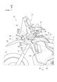
以上説明したように、本発明を適用した本実施の形態によれば、フロントタンク29fと、シュラウドウィング60及びシュラウドインテーク50と、を備えた鞍乗り型車両10において、吸入口54が設けられ、フロントタンク29fの左右側方に配置されて走行風をシート17の下方に導風するシュラウドインテーク50と、シュラウドインテーク50の前方に配置され、下面62bにより走行風を吸入口54に導き、上面62aにより走行風を、車体フレーム11等で構成される車体の側方に流すシュラウドウィング60と、シュラウドウィング60は、シュラウド側面部61よりも車体幅方向内側にウィング本体部62を備え、ウィング本体部62は、車体前後方向前側かつ車体幅方向内側に設けられた前内尖り部62cと、車体前後方向後側かつ車体幅方向外側に設けられた後外尖り部62dと、を備え、車体側面視で前方から、ウィング本体部62、吸入口54、フロントタンク29fの順に配置される。
As described above, according to the present embodiment to which the present invention is applied, in a saddle-
この構成によれば、下面62bの走行風をシュラウドインテーク50の吸入口54に導くことができるので、必要十分な吸気量を得られ易くできる。また、上面62aの走行風を車体フレーム11等で構成される車体の側方に流すことで、ライダーRに走行風が当たるのを抑制できる。よって、上記構成によれば、吸入口54が車体の前部に設けられる場合でも、必要十分な吸気量を得られ易く、ライダーRに走行風が当たることが抑制された鞍乗り型車両10を提供することができる。
With this configuration, the traveling wind on the
本実施の形態では、ウィング本体部62は、車体正面視で吸入口54と一部重なる。
この構成によれば、上面62aに当たる前方からの走行風を吸入口54以外に導風し易くでき、上面62aの走行風と、下面62bの走行風との使い分けをし易くできる。
In the present embodiment, the wing
With this configuration, the wind from the front hitting the
また、本実施の形態では、吸入口54は、車体側面視でヘッドパイプ18と一部重なる。
この構成によれば、吸入口54がヘッドパイプ18と重なる程度に前方にあるため、シュラウドウィング60が走行風を吸入口54に向けて、より導き易くなっていってる。
In addition, in this embodiment, the
According to this configuration, since the
また、本実施の形態では、ウィング本体部62は、車体後方に向けて上方に傾斜すると共に、車体幅方向内側に向けて上方に傾斜する。
この構成によれば、より精度よく、下面62bの走行風をシュラウドインテーク50の吸入口54に導くと共に、上面62aの走行風をライダーRの側方に流すことができる。
In the present embodiment, the wing
According to this configuration, the traveling wind on the
また、本実施の形態では、前内尖り部62cから後外尖り部62dに向けて、緩斜面62eから急斜面62fに角度が変わる。
この構成によれば、より精度よく、下面62bの走行風をシュラウドインテーク50の吸入口54に導くと共に、上面62aの走行風をライダーRの側方に流すことができる。
In this embodiment, the angle changes from the
According to this configuration, the traveling wind on the
また、本実施の形態では、ウィング本体部62は、シュラウド側面部61に対し、車体幅方向内側に後退翼形状を成す。
この構成によれば、より精度よく、下面62bの走行風をシュラウドインテーク50の吸入口54に導くと共に、上面62aの走行風をライダーRの側方に流すことができる。
In this embodiment, the wing
According to this configuration, the traveling wind on the
また、本実施の形態では、シュラウドインテーク50は、CFRP製である。
この構成によれば、シュラウドインテーク50について、走行時の振動による変形を抑制できるとともに、車体軽量化に繋げることができる。
In the present embodiment, the
According to this configuration, deformation of the
また、本実施の形態では、シュラウドウィング60は、PP製である。
この構成によれば、走行時の接触転倒でも、割れ難くでき、シュラウドウィング60の耐久性を向上させることができる。
In this embodiment, the
According to this configuration, the
[他の実施の形態]
上述した実施の形態は、あくまでも本発明の一態様を示すものであり、本発明の主旨を逸脱しない範囲で任意に変形及び応用が可能である。
[Other embodiments]
The above-described embodiment merely shows one aspect of the present invention, and any modification and application can be made without departing from the spirit and scope of the present invention.
上記実施の形態では、ウィング本体部62は、連続的に湾曲して傾斜している構成を例示したが、これに限定されない。例えば、ウィング本体部62は、非連続的に傾斜してもよい。具体的には、ウィング本体部62に異なる角度で傾斜する傾斜面と傾斜面との間に境界を形成する稜線が形成された構成でもよい。すなわち、ウィング本体部62は、段階的に傾斜してもよい。
In the above embodiment, the
上記実施の形態では、鞍乗り型車両10として、内燃機関としてのパワーユニット12を有する鞍乗り型車両10を例示したが、これに限定されない。例えば、鞍乗り型車両10としては、内燃機関としてのパワーユニット12を有しない車両、すなわち、電動車両でもよい。よって、上記実施の形態では、車体を駆動するパワーユニットとしてパワーユニット12を例示したが、パワーユニットとしては、駆動用の電動モータを備えるパワーユニットでもよい。また、エネルギー貯蔵部としての燃料タンク29に代えて、エネルギー貯蔵部は、駆動用のバッテリでもよい。ここで、電動車両の場合には、吸入口54を、パワーユニットやバッテリを冷却するために、走行風を取り入れる吸入口として利用可能である。
In the above embodiment, the saddle-
上記実施の形態では、鞍乗り型車両10として前輪13と後輪15とを有する自動二輪車を例に挙げて説明したが、本発明はこれに限定されるものではなく、本発明は、前輪または後輪を2つ備えた三輪の鞍乗り型車両や四輪以上を備えた鞍乗り型車両に適用可能である。
In the above embodiment, a motorcycle having a
[上記実施の形態によりサポートされる構成]
上記実施の形態は、以下の構成をサポートする。
[Configuration supported by the above embodiment]
The above embodiment supports the following configurations.
(構成1)エネルギー貯蔵部と、シュラウドウィング及びシュラウドインテークと、を備えた鞍乗り型車両において、吸入口が設けられ、前記エネルギー貯蔵部の左右側方に配置されて走行風をシートの下方に導風する前記シュラウドインテークと、前記シュラウドインテークの前方に配置され、シュラウドウィング下面により走行風を前記吸入口に導き、シュラウドウィング上面により走行風を車体の側方に流す前記シュラウドウィングと、前記シュラウドウィングは、シュラウドウィング側部よりも車体幅方向内側にウィング本体部を備え、前記ウィング本体部は、車体前後方向前側かつ車体幅方向内側に設けられた第1尖り部と、車体前後方向後側かつ車体幅方向外側に設けられた第2尖り部と、を備え、車体側面視で前方から、前記ウィング本体部、前記吸入口、前記エネルギー貯蔵部の順に配置されることを特徴とする鞍乗り型車両。
この構成によれば、シュラウドウィング下面の走行風をシュラウドインテークの吸入口に導くことができるので、必要十分な吸気量を得られ易くできる。また、シュラウドウィング上面の走行風を車体の側方に流すことで、ライダーに走行風が当たるのを抑制できる。よって、上記構成によれば、吸入口が車体の前部に設けられる場合でも、必要十分な吸気量を得られ易く、ライダーに走行風が当たることが抑制された鞍乗り型車両を提供することができる。
(Configuration 1) A saddle-ride type vehicle comprising an energy storage unit, a shroud wing, and a shroud intake, the shroud intakes being provided with an intake port and arranged on the left and right sides of the energy storage unit to guide a traveling wind downwardly to a seat, the shroud wing being arranged in front of the shroud intake and guiding the traveling wind to the intake port by means of a lower surface of the shroud wing and directing the traveling wind to the side of the vehicle body by means of an upper surface of the shroud wing, the shroud wing having a wing main body portion on the inner side in the vehicle body width direction than a side portion of the shroud wing, the wing main body portion having a first pointed portion arranged on the front side in the fore-and-aft direction of the vehicle body and on the inner side in the vehicle body width direction, and a second pointed portion arranged on the rear side in the fore-and-aft direction of the vehicle body and on the outer side in the vehicle body width direction, the saddle-ride type vehicle being characterized in that the wing main body portion, the intake port, and the energy storage unit are arranged in this order from the front when viewed from the side of the vehicle body.
According to this configuration, the traveling wind on the underside of the shroud wing can be guided to the intake port of the shroud intake, so that a necessary and sufficient intake volume can be easily obtained. Also, by directing the traveling wind on the upper surface of the shroud wing to the side of the vehicle body, it is possible to prevent the traveling wind from hitting the rider. Therefore, according to the above configuration, even if the intake port is provided at the front of the vehicle body, it is possible to provide a saddle-type vehicle that easily obtains a necessary and sufficient intake volume and prevents the traveling wind from hitting the rider.
(構成2)前記ウィング本体部は、車体正面視で前記吸入口と一部重なることを特徴とする請求項1に記載の鞍乗り型車両。
この構成によれば、シュラウドウィング上面に当たる前方からの走行風を吸入口以外に導風し易くでき、シュラウドウィング上面の走行風と、シュラウドウィング下面の走行風との使い分けをし易くできる。
(Configuration 2) The saddle-ride type vehicle according to
With this configuration, it is possible to easily guide the traveling wind from the front that hits the upper surface of the shroud wing to a location other than the intake port, making it easier to distinguish between the traveling wind on the upper surface of the shroud wing and the traveling wind on the lower surface of the shroud wing.
(構成3)前記吸入口は、車体側面視でヘッドパイプと一部重なることを特徴とする請求項1または2に記載の鞍乗り型車両。
この構成によれば、吸入口がヘッドパイプと重なる程度に前方にあるため、シュラウドウィングが走行風を吸入口に向けて、より導き易くなっていってる。
(Configuration 3) The saddle-type vehicle according to
With this configuration, the intake port is located far enough forward that it overlaps with the head pipe, making it easier for the shroud wing to direct the wind toward the intake port.
(構成4)前記ウィング本体部は、車体後方に向けて上方に傾斜すると共に、車体幅方向内側に向けて上方に傾斜することを特徴とする請求項1から3のいずれかに記載の鞍乗り型車両。
この構成によれば、より精度よく、シュラウドウィング下面の走行風をシュラウドインテークの吸入口に導くと共に、シュラウドウィング上面の走行風をライダーの側方に流すことができる。
(Configuration 4) A saddle-type vehicle according to any one of
According to this configuration, the traveling wind on the lower surface of the shroud wing can be more accurately guided to the intake port of the shroud intake, and the traveling wind on the upper surface of the shroud wing can be directed to the side of the rider.
(構成5)前記第1尖り部から前記第2尖り部に向けて、緩斜面から急斜面に角度が変わることを特徴とする請求項1から4のいずれかに記載の鞍乗り型車両。
この構成によれば、より精度よく、シュラウドウィング下面の走行風をシュラウドインテークの吸入口に導くと共に、シュラウドウィング上面の走行風をライダーの側方に流すことができる。
(Configuration 5) A saddle-type vehicle according to any one of
According to this configuration, the traveling wind on the lower surface of the shroud wing can be more accurately guided to the intake port of the shroud intake, and the traveling wind on the upper surface of the shroud wing can be directed to the side of the rider.
(構成6)前記ウィング本体部は、前記シュラウドウィング側部に対し、車体幅方向内側に後退翼形状を成すことを特徴とする請求項1から5のいずれかに記載の鞍乗り型車両。
この構成によれば、より精度よく、シュラウドウィング下面の走行風をシュラウドインテークの吸入口に導くと共に、シュラウドウィング上面の走行風をライダーの側方に流すことができる。
(Configuration 6) The saddle-ride type vehicle according to any one of
According to this configuration, the traveling wind on the lower surface of the shroud wing can be more accurately guided to the intake port of the shroud intake, and the traveling wind on the upper surface of the shroud wing can be directed to the side of the rider.
(構成7)前記シュラウドインテークは、CFRP製であることを特徴とする請求項1から6のいずれかに記載の鞍乗り型車両。
この構成によれば、シュラウドインテークについて、走行時の振動による変形を抑制できるとともに、車体軽量化に繋げることができる。
(Configuration 7) The saddle-type vehicle according to any one of
With this configuration, deformation of the shroud intake due to vibrations during driving can be suppressed, and the vehicle body can be made lighter.
(構成8)前記シュラウドウィングは、PP製であることを特徴とする請求項1から7のいずれかに記載の鞍乗り型車両。
この構成によれば、走行時の接触転倒でも、割れ難くでき、シュラウドウィングの耐久性を向上させることができる。
(Configuration 8) A saddle-type vehicle according to any one of
According to this configuration, the shroud wing is less likely to crack even if it is hit and overturned while traveling, and the durability of the shroud wing can be improved.
10 鞍乗り型車両
11 車体フレーム(車体)
17 シート
18 ヘッドパイプ
29f フロントタンク(エネルギー貯蔵部)
50 シュラウドインテーク
54 吸入口
60 シュラウドウィング
61 シュラウド側面部(シュラウドウィング側部)
62 ウィング本体部
62a 上面(シュラウドウィング上面)
62b 下面(シュラウドウィング下面)
62c 前内尖り部(第1尖り部)
62d 後外尖り部(第2尖り部)
62e 緩斜面
62f 急斜面
10 Saddle-
17
50
62
62b Lower surface (lower surface of shroud wing)
62c Front inner pointed portion (first pointed portion)
62d rear outer pointed portion (second pointed portion)
Claims (8)
吸入口(54)が設けられ、前記エネルギー貯蔵部(29f)の左右側方に配置されて走行風をシート(17)の下方に導風する前記シュラウドインテーク(50)と、
前記シュラウドインテーク(50)の前方に配置され、シュラウドウィング下面(62b)により走行風を前記吸入口(54)に導き、シュラウドウィング上面(62a)により走行風を車体(11)の側方に流す前記シュラウドウィング(60)と、
前記シュラウドウィング(60)は、シュラウドウィング側部(61)よりも車体幅方向内側にウィング本体部(62)を備え、
前記ウィング本体部(62)は、車体前後方向前側かつ車体幅方向内側に設けられた第1尖り部(62c)と、車体前後方向後側かつ車体幅方向外側に設けられた第2尖り部(62d)と、を備え、
車体側面視で前方から、前記ウィング本体部(62)、前記吸入口(54)、前記エネルギー貯蔵部(29f)の順に配置される
ことを特徴とする鞍乗り型車両。 A saddle-type vehicle including an energy storage unit (29f), a shroud wing (60), and a shroud intake (50),
the shroud intake (50) is provided with an intake port (54), is arranged on the left and right sides of the energy storage unit (29f), and guides a traveling wind to below the seat (17);
the shroud wing (60) disposed in front of the shroud intake (50), guiding a running wind to the intake port (54) through a shroud wing lower surface (62b) and directing the running wind to a side of the vehicle body (11) through a shroud wing upper surface (62a);
The shroud wing (60) includes a wing main body portion (62) located on the inner side in the vehicle body width direction than a shroud wing side portion (61),
The wing main body portion (62) includes a first pointed portion (62c) provided on a front side in the vehicle body longitudinal direction and on an inner side in the vehicle body width direction, and a second pointed portion (62d) provided on a rear side in the vehicle body longitudinal direction and on an outer side in the vehicle body width direction,
a wing body portion (62), an intake port (54), and an energy storage portion (29f) are arranged in this order from the front in a side view of the vehicle body.
ことを特徴とする請求項1に記載の鞍乗り型車両。 The saddle-ride type vehicle according to claim 1, wherein the wing main body (62) partially overlaps with the intake port (54) when viewed from the front of the vehicle body.
ことを特徴とする請求項1または2に記載の鞍乗り型車両。 3. The saddle-ride type vehicle according to claim 1, wherein the intake port (54) partially overlaps with a head pipe (18) in a side view of the vehicle body.
ことを特徴とする請求項1または2に記載の鞍乗り型車両。 The saddle-ride type vehicle according to claim 1 or 2, characterized in that the wing main body (62) is inclined upward toward the rear of the vehicle body and is also inclined upward toward an inner side in a width direction of the vehicle body.
ことを特徴とする請求項1または2に記載の鞍乗り型車両。 The saddle-type vehicle according to claim 1 or 2, characterized in that an angle changes from a gentle slope (62e) to a steep slope (62f) from the first pointed portion (62c) to the second pointed portion (62d).
ことを特徴とする請求項1または2に記載の鞍乗り型車両。 3. The saddle-ride type vehicle according to claim 1, wherein the wing main body portion (62) forms a swept-back shape on an inner side in a vehicle width direction relative to the shroud wing side portion (61).
ことを特徴とする請求項1または2に記載の鞍乗り型車両。 The saddle-ride type vehicle according to claim 1 or 2, characterized in that the shroud intake (50) is made of CFRP.
ことを特徴とする請求項7に記載の鞍乗り型車両。 The saddle-type vehicle according to claim 7, characterized in that the shroud wing (60) is made of PP.
Priority Applications (3)
| Application Number | Priority Date | Filing Date | Title |
|---|---|---|---|
| JP2023148441A JP7689165B2 (en) | 2023-09-13 | 2023-09-13 | Saddle type vehicle |
| CN202422131314.7U CN222973554U (en) | 2023-09-13 | 2024-08-30 | Saddle-type vehicle |
| US18/829,429 US20250083764A1 (en) | 2023-09-13 | 2024-09-10 | Saddle-ride vehicle |
Applications Claiming Priority (1)
| Application Number | Priority Date | Filing Date | Title |
|---|---|---|---|
| JP2023148441A JP7689165B2 (en) | 2023-09-13 | 2023-09-13 | Saddle type vehicle |
Publications (2)
| Publication Number | Publication Date |
|---|---|
| JP2025041255A true JP2025041255A (en) | 2025-03-26 |
| JP7689165B2 JP7689165B2 (en) | 2025-06-05 |
Family
ID=94873347
Family Applications (1)
| Application Number | Title | Priority Date | Filing Date |
|---|---|---|---|
| JP2023148441A Active JP7689165B2 (en) | 2023-09-13 | 2023-09-13 | Saddle type vehicle |
Country Status (3)
| Country | Link |
|---|---|
| US (1) | US20250083764A1 (en) |
| JP (1) | JP7689165B2 (en) |
| CN (1) | CN222973554U (en) |
Citations (5)
| Publication number | Priority date | Publication date | Assignee | Title |
|---|---|---|---|---|
| JP2017165387A (en) * | 2016-03-15 | 2017-09-21 | 本田技研工業株式会社 | Radiator shroud for vehicle |
| JP2020040521A (en) * | 2018-09-11 | 2020-03-19 | 川崎重工業株式会社 | Cover structure of saddle type vehicle |
| JP2022153064A (en) * | 2021-03-29 | 2022-10-12 | 本田技研工業株式会社 | saddle-riding vehicle |
| JP2023034296A (en) * | 2021-08-30 | 2023-03-13 | 本田技研工業株式会社 | Saddle-riding type vehicle |
| JP2024155427A (en) * | 2023-04-21 | 2024-10-31 | スズキ株式会社 | Under cowl |
-
2023
- 2023-09-13 JP JP2023148441A patent/JP7689165B2/en active Active
-
2024
- 2024-08-30 CN CN202422131314.7U patent/CN222973554U/en active Active
- 2024-09-10 US US18/829,429 patent/US20250083764A1/en active Pending
Patent Citations (5)
| Publication number | Priority date | Publication date | Assignee | Title |
|---|---|---|---|---|
| JP2017165387A (en) * | 2016-03-15 | 2017-09-21 | 本田技研工業株式会社 | Radiator shroud for vehicle |
| JP2020040521A (en) * | 2018-09-11 | 2020-03-19 | 川崎重工業株式会社 | Cover structure of saddle type vehicle |
| JP2022153064A (en) * | 2021-03-29 | 2022-10-12 | 本田技研工業株式会社 | saddle-riding vehicle |
| JP2023034296A (en) * | 2021-08-30 | 2023-03-13 | 本田技研工業株式会社 | Saddle-riding type vehicle |
| JP2024155427A (en) * | 2023-04-21 | 2024-10-31 | スズキ株式会社 | Under cowl |
Also Published As
| Publication number | Publication date |
|---|---|
| JP7689165B2 (en) | 2025-06-05 |
| US20250083764A1 (en) | 2025-03-13 |
| CN222973554U (en) | 2025-06-13 |
Similar Documents
| Publication | Publication Date | Title |
|---|---|---|
| JP5771100B2 (en) | Saddle riding vehicle | |
| JP6663451B2 (en) | Saddle-type vehicle | |
| US20090218152A1 (en) | Motorcycle and intake device thereof | |
| JP4684826B2 (en) | Front structure of saddle-ride type vehicle | |
| JP6196083B2 (en) | Motorcycle | |
| US8061468B2 (en) | Vehicle | |
| CN110329409A (en) | Straddle-type vehicle | |
| JP4856485B2 (en) | Motorcycle cowling structure | |
| JP2015016757A (en) | Motorcycle | |
| US9045188B2 (en) | Lower part structure for vehicle | |
| EP2042414B1 (en) | Motorcycle comprising an air intake port structure | |
| JP7689165B2 (en) | Saddle type vehicle | |
| JP5872508B2 (en) | Motorcycle rear frame structure | |
| JP6492940B2 (en) | Saddle riding vehicle | |
| JP6943538B2 (en) | Saddle-type vehicle | |
| CN110155226B (en) | Saddle-ride type vehicle | |
| JP7480200B2 (en) | Saddle type vehicle | |
| CN101712352B (en) | Motor bicycle | |
| CN112533820A (en) | Saddle-ride type vehicle | |
| JP7206840B2 (en) | Motorcycle air intake duct structure | |
| JP7570395B2 (en) | Saddle-type vehicle | |
| CN110300699B (en) | straddle vehicle | |
| JP7549131B2 (en) | Saddle-type vehicle | |
| JP7692951B2 (en) | Exterior part structure | |
| JP7431794B2 (en) | saddle type vehicle |
Legal Events
| Date | Code | Title | Description |
|---|---|---|---|
| A621 | Written request for application examination |
Free format text: JAPANESE INTERMEDIATE CODE: A621 Effective date: 20240328 |
|
| TRDD | Decision of grant or rejection written | ||
| A01 | Written decision to grant a patent or to grant a registration (utility model) |
Free format text: JAPANESE INTERMEDIATE CODE: A01 Effective date: 20250520 |
|
| A61 | First payment of annual fees (during grant procedure) |
Free format text: JAPANESE INTERMEDIATE CODE: A61 Effective date: 20250526 |
|
| R150 | Certificate of patent or registration of utility model |
Ref document number: 7689165 Country of ref document: JP Free format text: JAPANESE INTERMEDIATE CODE: R150 |