JP2025041247A - Power receiving device, mobile object, wireless power transmission system, and coil unit - Google Patents
Power receiving device, mobile object, wireless power transmission system, and coil unit Download PDFInfo
- Publication number
- JP2025041247A JP2025041247A JP2023148426A JP2023148426A JP2025041247A JP 2025041247 A JP2025041247 A JP 2025041247A JP 2023148426 A JP2023148426 A JP 2023148426A JP 2023148426 A JP2023148426 A JP 2023148426A JP 2025041247 A JP2025041247 A JP 2025041247A
- Authority
- JP
- Japan
- Prior art keywords
- power receiving
- coil
- power
- circuit
- receiving coil
- Prior art date
- Legal status (The legal status is an assumption and is not a legal conclusion. Google has not performed a legal analysis and makes no representation as to the accuracy of the status listed.)
- Pending
Links
Images
Landscapes
- Charge And Discharge Circuits For Batteries Or The Like (AREA)
- Current-Collector Devices For Electrically Propelled Vehicles (AREA)
- Electric Propulsion And Braking For Vehicles (AREA)
Abstract
Description
本実施形態は、受電装置、移動体、無線電力伝送システム、及びコイルユニットに関する。 This embodiment relates to a power receiving device, a mobile object, a wireless power transmission system, and a coil unit.
送電コイルを含む送電装置から受電コイルを含む受電装置へ向けて電力を送電する無線電力伝送システムが提案されている。しかし、消費電力が多く、高電圧で駆動する装置を急速に充電するために大電流で無線電力伝送を行うと、通過抵抗によりシステム内で発生する熱による障害が生じる可能性がある。そこで、解決方法の一つとして、一つの受電コイルに流れる電流を分散させるため、受電コイル、および受電コイルに直列接続された受電回路を備えている受電ユニットを複数並列に接続し、これらの受電ユニットの出力を加算・合成し負荷に出力する技術が知られている。しかし、受電ユニットを並列接続すると、受電ユニットの出力にばらつきが生じた場合、受電ユニット間を電流が逆流する可能性があるという課題がある。 A wireless power transmission system has been proposed that transmits power from a power transmission device including a power transmission coil to a power receiving device including a power receiving coil. However, when wireless power transmission is performed at a large current in order to rapidly charge a device that consumes a lot of power and operates at a high voltage, there is a possibility that a failure will occur due to heat generated in the system due to passing resistance. As a solution to this problem, a technology is known in which multiple power receiving units each having a power receiving coil and a power receiving circuit connected in series to the power receiving coil are connected in parallel to distribute the current flowing through one power receiving coil, and the outputs of these power receiving units are added and combined to be output to a load. However, when power receiving units are connected in parallel, there is a problem in that if there is variation in the output of the power receiving units, there is a possibility that current will flow back between the power receiving units.
本発明が解決しようとする課題は、一つの受電ユニットに流れる電流を分散させつつ、受電ユニット間の電流の逆流が起こらない受電装置、移動体、無線電力伝送システム、及びコイルユニットを提供することである。 The problem that the present invention aims to solve is to provide a power receiving device, a mobile body, a wireless power transmission system, and a coil unit that can distribute the current flowing through one power receiving unit while preventing reverse current flow between power receiving units.
実施形態の受電装置は、第1受電コイルと、第2受電コイルと、第1受電回路と、第2受電回路と、加算部とを備える。第1コイルの軸に対して垂直な第1受電コイルの断面である第1受電面と、第2コイルの軸に対して垂直な第2受電コイルの断面である第2受電面とを垂直に投影したとき、投影された第1受電面及び第2受電面は少なくとも一部が重複する。第1受電回路は第1受電コイルに接続され、第2受電回路は第2受電コイルに接続される。加算部は、第1受電回路及び第2受電回路が出力した電流を電流加算する。 The power receiving device of the embodiment includes a first power receiving coil, a second power receiving coil, a first power receiving circuit, a second power receiving circuit, and an adder. When a first power receiving surface, which is a cross section of the first power receiving coil perpendicular to the axis of the first coil, and a second power receiving surface, which is a cross section of the second power receiving coil perpendicular to the axis of the second coil, are projected vertically, the projected first power receiving surface and second power receiving surface at least partially overlap. The first power receiving circuit is connected to the first power receiving coil, and the second power receiving circuit is connected to the second power receiving coil. The adder adds the currents output by the first power receiving circuit and the second power receiving circuit.
以下、実施形態について、図面を参照して説明する。なお、実施形態は本発明を限定するものではない。図面中の同一部分には、同一番号を付してその詳しい説明は適宜省略し、異なる部分について説明する。なお、図面は模式的または概念的なものであり、各部分の厚みと幅との関係、部分間の大きさの比率などは、必ずしも現実のものと同一とは限らない。また、同じ部分を表す場合であっても、図面により互いの寸法や比率が異なって表される場合もある。 The following describes the embodiments with reference to the drawings. Note that the present invention is not limited to the embodiments. Identical parts in the drawings are given the same numbers, and detailed descriptions thereof are omitted as appropriate, and different parts are described. Note that the drawings are schematic or conceptual, and the relationship between the thickness and width of each part, the size ratio between parts, and the like are not necessarily the same as in reality. Even when the same parts are shown, the dimensions and ratios between them may be shown differently depending on the drawing.
さらに、各図中に示すX軸、Y軸、及びZ軸を用いて各部分の配置および構成を説明する。X軸、Y軸、Z軸は、相互に直交し、それぞれX方向、Y方向、Z方向を表す。また、コイルを貫く磁束に平行な方向をZ方向とし、送電コイルから受電コイルへ向かう方向を正、その反対方向を負として説明する場合がある。 The arrangement and configuration of each part will be explained using the X-axis, Y-axis, and Z-axis shown in each figure. The X-axis, Y-axis, and Z-axis are mutually perpendicular and represent the X-direction, Y-direction, and Z-direction, respectively. In addition, the direction parallel to the magnetic flux passing through the coil will be referred to as the Z-direction, and the direction from the transmitting coil to the receiving coil will sometimes be described as positive, and the opposite direction as negative.
さらに、第1受電コイル21a及び第2受電コイル21bを含む、個々の受電コイルの総称を受電コイル21(二次コイルともいう)とすることがある。
Furthermore, the individual receiving coils, including the first receiving
さらに、第1受電コイル21aに接続された受電回路20a及び第2受電コイル21bに接続された受電回路20bを含む、受電回路をまとめて受電回路20とする。
Furthermore, the power receiving circuits including the
(第1の実施形態)
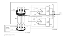
図1は、本実施形態における無線電力伝送システム1の概略図の一例である。本実施形態において、無線電力伝送システム1は、受電装置3と、受電装置3へ向けて無線電力を送電する送電装置2と、を備える。送電装置2は、高周波発生回路10と送電コイル11(一次コイルともいう)とを備え、送電コイル11は高周波発生回路10に接続される。受電装置3は、第1受電コイル21aと、第2受電コイル21bと、第1受電コイル21aに接続された第1受電回路20aと、第2受電コイル21bに接続された第2受電回路20bと、第1受電回路20a及び第2受電回路20bが出力した電流を電流加算する加算部25と、を備える。以下、第1受電コイル21aと第2受電コイル21bとを含む受電コイルの集合体をコイルユニット21uとして説明する。
First Embodiment
1 is an example of a schematic diagram of a wireless power transmission system 1 in this embodiment. In this embodiment, the wireless power transmission system 1 includes a
高周波発生回路10は、高周波の交流電流を出力する回路である。
The high-
送電コイル11は、少なくとも一部が環状に巻回されたコイルである。基本的に環の形状は円形であるが、楕円形や多角形でもよい。
The
第1受電回路20aは、整流回路23aを備える。整流回路23aは、第1受電コイル21aの両端に接続される。整流回路23aは、例えば、4つのダイオードをブリッジ接続した全波整流回路である。ただし、整流回路23aの構成はこれに限定されず、交流電流を直流電流に変換可能な構成であればよい。
The first
また、第1受電回路20aは、第1受電コイル21aに並列に接続されたキャパシタンス22aを含んでもよい。このとき、キャパシタンス22aの両端には整流回路23aが接続されている。キャパシタンス22aは、第1受電コイル21aと共に共振回路を構成するためのものである。本明細書において、キャパシタンスとは、コンデンサ等の実体を有し、無線給電に用いる周波数で十分な容量成分を有する電子部品である。ただし、受電コイルとして用いるソレノイド形状巻線で、隣接の巻線間の浮遊容量も含む総称をキャパシタンスとしてもよい。図1に示す実施形態では、キャパシタンス22aを第1受電コイル21aに対して並列に接続している。また、図1には図示しないが、送電装置2に含まれるコンデンサ22cは送電コイル11に直列に接続されているとする。これは、いわゆるS-P(送電側シリーズ-受電側パラレル)方式と呼ばれ、回路の信頼性を高めることができる。
The first
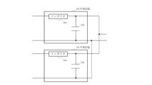
また、第1受電回路20aは、平滑回路24を含んでもよい。図2は、平滑回路24の概略図の一例である。図2に示すように、平滑回路24は請求回路23aの両端に接続され、キャパシタンス22bを含む回路である。平滑回路24はインダクタ26aをさらに含んでいてもよい。本実施形態において、インダクタ26aは、銅線等の配線材料が有するインダクタンス成分のこととしてもよいし、回路に流れる電流が大きい場合、リアクトルとしてもよい。インダクタ26aの種類を変更することにより、平滑回路24によって平滑化される電流の周波数を調整することが可能となる。
The first
なお、本実施形態において、第2受電コイル21bは上述した第1受電コイル21aと同様の構成としてもよく、第2受電回路20bは上述した第1受電回路20aと同様の構成としてもよい。
In this embodiment, the second
複数の受電コイル21のそれぞれに接続された回路どうしが電気的に接続され、第1受電回路20a及び第2受電回路20bから出力された電流が電流加算される箇所を加算部25とする。
The circuits connected to each of the multiple
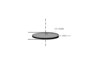
続いて、受電コイル21について詳細に説明する。受電コイル21は、少なくとも一部が環状に巻回されたコイルである。基本的に環の形状は円形であるが、楕円形や多角形でもよい。また、以下本明細書中では、図3に示すように、受電コイル21の軸(破線)に対して垂直な受電コイル21の断面(網掛け部)を受電面21Sとし、第1受電コイル21aの受電面を第1受電面、第2受電コイル21bの受電面を第2受電面とする。
Next, the
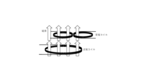
一般に、1個の受電コイルをN個に分けて並列接続する場合、各受電コイルに接続された受電回路に流れる電流の大きさは、元の受電回路の(1/N)となるため、1個の受電コイルをN個に分けることにより、各々の受電回路に流れる電流の大きさが小さくなり、回路が障害を起こしにくくなる。さらにこのとき、各受電回路における熱損失は(1/N)^2倍に減少する。従って、受電装置全体の熱損失の合計は、N×((1/N)^2)= (1/N)倍に減少する。しかし、複数の受電コイルを受電面が重ならないように並べて配置する場合、受電コイルの搭載面積が大きくなるという課題がある。さらに、複数の受電コイルを受電面が重ならないように並べて配置する場合、複数の受電コイルに印加される磁束の密度および位相に違いが生じることにより、各受電コイルに接続された受電回路に流れる電流の大きさおよび位相にも違いが生じる。これにより、加算部で電流が逆流するおそれがあるといった課題がある。図4に、各受電コイルに印加される磁束が異なる例を示す。図4において、受電コイルに印加される磁束の密度が異なる。このように、従来の無線電力伝送システムにおいて、送電コイルと、受電コイルとの位置関係によっては、各受電コイルに印加される磁束の密度にばらつきが生じることがあった。従って、各受電コイルに接続された受電回路を流れる電流の大きさにもばらつきが生じ、受電回路内を電流が逆流する可能性があり、従来の受電装置において、受電回路の電流が大きい場合は、受電回路内に逆流防止回路などの保護手段を設ける必要があった。 Generally, when one receiving coil is divided into N parts and connected in parallel, the magnitude of the current flowing through the receiving circuit connected to each receiving coil is (1/N) of the original receiving circuit. Therefore, by dividing one receiving coil into N parts, the magnitude of the current flowing through each receiving circuit is reduced, making the circuit less likely to malfunction. Furthermore, at this time, the heat loss in each receiving circuit is reduced by (1/N)^2. Therefore, the total heat loss of the entire receiving device is reduced by N x ((1/N)^2) = (1/N) times. However, when multiple receiving coils are arranged side by side so that their receiving surfaces do not overlap, there is a problem that the mounting area of the receiving coil becomes large. Furthermore, when multiple receiving coils are arranged side by side so that their receiving surfaces do not overlap, differences occur in the density and phase of the magnetic flux applied to the multiple receiving coils, which causes differences in the magnitude and phase of the current flowing through the receiving circuit connected to each receiving coil. This causes a problem that the current may flow backward in the adder. FIG. 4 shows an example in which the magnetic flux applied to each receiving coil is different. In FIG. 4, the density of the magnetic flux applied to the receiving coil is different. In this way, in a conventional wireless power transmission system, the density of the magnetic flux applied to each receiving coil can vary depending on the positional relationship between the power transmission coil and the receiving coil. Therefore, the magnitude of the current flowing through the receiving circuit connected to each receiving coil also varies, and there is a possibility that the current may flow back in the receiving circuit. In a conventional power receiving device, when the current in the receiving circuit is large, it was necessary to provide a protective measure such as a backflow prevention circuit in the receiving circuit.
そこで、本実施形態によれば、第1受電面と第2受電面とを垂直にXY平面に投影したとき、投影された第1受電面及び第2受電面は少なくとも一部が重複するように受電コイル21を配置する。一例として、第1受電面及び第2受電面付近の磁束方向は同一であるが、磁束密度がXY平面内の位置に対して大きく変化する場合を説明する。このとき、垂直にXY平面に投影された第1受電面と第2受電面は、受電面の面積がほぼ同一で、投影された受電面のほとんどが重複することが好ましい。具体的には、垂直にXY平面に投影された第1受電面と第2受電面は、第1受電面の面積の95%以上が重複することが好ましい。95%以上が重複する場合、第1受電コイル21aおよび第2受電コイル21bの誘導電流の差は5%以下に抑えることが可能である。なお、投影された両受電面は、第1受電面の面積の97%以上が重複することがより好ましい。97%以上が重複する場合、第1受電コイル21aおよび第2受電コイル21bの誘導電流の差は3%以下に抑えることが可能である。なお、投影された両受電面は、第1受電面の面積の99%以上が重複することがさらに好ましい。99%以上が重複する場合、第1受電コイル21aおよび第2受電コイル21bの誘導電流の差は1%以下に抑えることが可能である。なお、投影された両受電面が一致することが最も好ましい。
Therefore, according to this embodiment, when the first and second power receiving surfaces are projected vertically onto the XY plane, the
また、垂直にXY平面に投影された第1受電面の中心と第2受電面の中心とが近いほど好ましい。一例として、第1受電面及び第2受電面付近の磁束方向は同一であるが、磁束密度がXY平面内の位置に対して大きく変化する場合を説明する。例えば、受電面が円形である場合、投影された第1受電面の中心と第2受電面の中心との距離は、第1受電面の内径の4.8%以下であることが好ましい。内径の4.8%以下である場合、第1受電コイル21aおよび第2受電コイル21bの誘導電流の差は5%以下に抑えることが可能である。なお、投影された両受電面の中心と第2受電面の中心との距離は、第1受電面の内径の2.88%以下であることがより好ましい。内径の2.88%以下である場合、第1受電コイル21aおよび第2受電コイル21bの誘導電流の差は3%以下に抑えることが可能である。なお、投影された両受電面の中心と第2受電面の中心との距離は、第1受電面の内径の0.96%以下であることがより好ましい。内径の0.96%以下である場合、第1受電コイル21aおよび第2受電コイル21bの誘導電流の差は1%以下に抑えることが可能である。なお、投影された両受電面の中心は一致することが最も好ましい。
In addition, the closer the center of the first power receiving surface and the center of the second power receiving surface projected vertically onto the XY plane, the better. As an example, a case will be described in which the magnetic flux direction near the first power receiving surface and the second power receiving surface is the same, but the magnetic flux density changes significantly with respect to the position in the XY plane. For example, when the power receiving surface is circular, it is preferable that the distance between the center of the projected first power receiving surface and the center of the second power receiving surface is 4.8% or less of the inner diameter of the first power receiving surface. When it is 4.8% or less of the inner diameter, it is possible to suppress the difference in the induced current of the first
このように、投影された第1受電面及び第2受電面の少なくとも一部が重複し、両受電面の中心が近くなるように配置することにより、受電コイル21aおよび第2受電コイル21bに印加される磁束の密度および位相が揃うことで、各受電コイルの誘導電流の差を抑えることができ、加算部で電流が逆流するおそれがなくなる。加えて、コイルユニット21uの搭載面積を小さくすることができる。つまり、図1に示すように、投影された第1受電面及び第2受電面は少なくとも一部が重複し、第1受電コイル21aを流れる電流は、第1受電コイル21aに接続された第1受電回路20aに出力され、第2受電コイル21bを流れる電流は、第2受電コイル21bに接続された第2受電回路20bに出力されるコイルユニット21uを無線電力伝送システムに用いることにより、送電コイル11とコイルユニット21uとの位置関係にかかわらず、各々の受電コイル21に印加される磁束が共通化されるため、各々の受電コイル21に接続された受電回路20に流れる電流の振幅および位相に違いが生じない。従って、本実施形態によれば、従来各々の受電回路に実装されていた逆流防止回路が不要になる、あるいは、簡略化できることにより、受電装置3の軽量化が可能である。さらに、本実施形態による構成は受電装置全体の熱損失の合計を抑制可能であるため、熱損失の際に発生した熱を放熱するための放熱器の体積も同時に小さくすることができる。
In this way, by arranging the projected first and second power receiving surfaces so that at least a portion of them overlap and the centers of both power receiving surfaces are close to each other, the density and phase of the magnetic flux applied to the
さらに、第1受電面の面積と第2受電面の面積はほぼ等しいことが好ましい。一例として、第1受電面及び第2受電面付近の磁束密度が一様である場合を説明する。このとき、第1受電面の面積と第2受電面の面積との差は±5%以内であることが好ましく、±3%であることがより好ましい。なお、両受電面の面積差は±1%以内であることがさらに好ましい。なお、両受電面の面積が一致することが最も好ましい。このように、第1受電面と第2受電面の面積を近づけることにより、送電コイル11とコイルユニット21uとの位置関係に関わらず、複数の受電コイル21に印加される磁束がほぼ等しくなるため、大きさおよび位相がほぼそろった誘導電流が、各受電コイル21に接続された受電回路20に流れる。またこのとき、第1受電面と第2受電面の形状が同じであることが好ましく、受電面21Sの形状は、円形、楕円形、多角形などである。
Furthermore, it is preferable that the area of the first power receiving surface and the area of the second power receiving surface are almost equal. As an example, a case where the magnetic flux density near the first power receiving surface and the second power receiving surface is uniform will be described. In this case, the difference between the area of the first power receiving surface and the area of the second power receiving surface is preferably within ±5%, and more preferably ±3%. It is even more preferable that the area difference between the two power receiving surfaces is within ±1%. It is most preferable that the areas of the two power receiving surfaces are the same. In this way, by bringing the areas of the first power receiving surface and the second power receiving surface closer together, the magnetic flux applied to the multiple power receiving coils 21 becomes almost equal regardless of the positional relationship between the
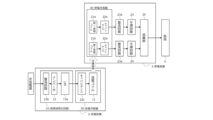
図5は、本実施形態における無線電力伝送システム1のブロック図の一例である。以下このブロック図を用いて、無線電力伝送システム1を用いた無線電力伝送を説明する。 Figure 5 is an example of a block diagram of the wireless power transmission system 1 in this embodiment. Hereinafter, wireless power transmission using the wireless power transmission system 1 will be described using this block diagram.
高周波発生回路10は、整流回路23bと、インバータ12と、LPF13a(高域阻止フィルタ)とを含む。
The high
整流回路23bは、外部電源から入力される交流電流を直流電流へと変換する。
The
インバータ12は、整流回路23bから出力された直流電流を高周波の交流電流へと変換する。高周波とは、数kHzから十数MHzまでを想定しており、例えば9kHz、85kHz、6.78MHz、13.56MHz等である。インバータ12は、出力電圧が目標電圧に一致するようにフィードバック制御を行ってもよい。
The
LPF13aは、インバータ12から出力する高周波交流電流のうち、基本波成分を除く高調波成分を減衰させて、送電コイル11から発生させる高周波交番磁界のうち高調波成分が、使用する国等の法令やガイドラインで定められる基準以下となるように高域阻止を行う。LPF13aを通過した交流電流は、送電共振器30へ向けて出力される。本実施形態において、高周波発生回路10が出力する交流電流の周波数帯としては、数kHzから十数MHzを想定しており、例えば9kHz、85kHz、6.78MHz、13.56MHz等である。
The
送電共振器30は、キャパシタンス22cと、送電コイル11とを含む。キャパシタンス22cは、送電コイル11と共に共振回路を構成するためのものである。送電共振器30は、無線電力伝送に用いる共振周波数に近い周波数の共振を発生させる。送電共振器30は、キャパシタンス22cと送電コイル11の他にも構成要素を含んでいてもよい。例えば、送電共振器30は、LPFを含んでいてもよい。キャパシタンス22cは、受電共振器40に含まれるキャパシタンス22aとは異なる種類のキャパシタンスを用いてもよい。
The power transmission resonator 30 includes a
送電コイル11は、交流電流が流れることで交番磁界を発生させる。
The
受電共振器40は、第1受電コイル21a及び第2受電コイル21bと、キャパシタンス22aとを含む。キャパシタンス22aは、受電コイル21と共に共振回路を構成するためのものである。受電共振器40は、無線電力伝送に用いる共振周波数に近い周波数の共振を発生させる。
The power receiving resonator 40 includes a first
第1受電コイル21a及び第2受電コイル21bには、送電コイル11で発生した交番磁界が印加される。第1受電コイル21a及び第2受電コイル21bに交番磁界が印加されると、第1受電コイル21及び第2受電コイル21bに誘導電流が流れる。即ち、第1受電コイル21a及び第2受電コイル21bを含むコイルユニット21uと送電コイル11とが対向した状態において、送電コイル11が発生させた磁束によりコイルユニット21uに電流が流れ、無線電力伝送システム1において、送電装置2から受電装置3へ向けた無線電力伝送が可能となる。ここで、コイルユニット21uと送電コイル11が対向した状態とは、受電面21Sと送電面が略平行に向かい合った状態のことであり、送電面とは、受電コイル21における受電面21Sと同様に、送電コイル11における送電コイル11の内部空間の送電コイル11の軸に対して垂直な断面のことである。図5では、第1受電コイル21aと送電コイル11の間に第2受電コイル21を配置しているが、本ブロック図は受電コイル21の配置を限定するものではない。
An alternating magnetic field generated by the
整流回路23aは、受電コイル21にて発生した交流電流の誘導電流を脈流電流へと変換する。ここで、脈流とは、電流の流れる方向が一定で、電流および電圧の大きさが周期的または不定期な変動を伴う電流とする。
The
平滑回路24は、整流回路23aが出力した電流を平滑化可能である。例えば、平滑回路24は、整流回路23aから出力された脈流電流を平滑化し、直流電流を出力する。ここで、直流電流とは、電流の流れる方向が一定で、電流および電圧の大きさがほとんど一定の電流とする。
The smoothing
加算部25は、並列接続された複数の平滑回路24から出力された直流電流を電流加算する。これにより、受電装置3は大電流を出力することができる。得られた大電流は、受電装置3に接続された負荷4へ向けて出力される。
The
このように、投影された第1受電面及び第2受電面の少なくとも一部が重複し、第1受電コイル21aを流れる電流は第1受電回路20aに出力され、第2受電コイル21bに流れる電流が第2受電回路20bに出力されるコイルユニット21uを無線電力伝送システム1に用い、各受電回路20の出力を電流加算することにより、ひとつの受電コイルに流れる電流を分散させつつ、受電回路間の電流の逆流が起こらない無線電力伝送システムを提供することができる。さらに、受電コイル21の搭載面積や放熱器の体積を抑制することにより受電装置全体を小さくすることができるため、移動体への搭載が容易になる。
In this way, by using a
ただし、受電装置3の実施形態は、上述の内容に限定されない。例えば、図1には2つの受電コイル21を図示したが、受電コイル21の個数はこれに限定されない。3つ以上の受電コイル21を用いてもよい。このとき、第1受電コイル21a及び第2受電コイル21b以外の受電コイル21から任意に選択した受電コイルを第3の受電コイルとし、第1受電面と同様に第3受電面を定義する。垂直にXY平面に投影された第3受電面の少なくとも一部と、同じく垂直にXY平面に投影された第1受電面または第2受電面の少なくとも一部とが重複することが好ましい。さらに、投影された第1受電面、第2受電面、及び第3受電面の3つが重複する領域があることがさらに好ましい。また、第1~3受電コイル以外の受電コイルも同様に、投影された受電面が投影された少なくとも一つの他の受電面の少なくとも一部と重複することが好ましい。さらに、コイルユニット21uに含まれるそれぞれの受電コイル21の受電面21Sを垂直にXY平面に投影したとき、投影されたすべての受電面21Sが重複する領域があることが最も好ましい。
However, the embodiment of the
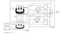
また、図1にはS-P方式を用いた場合を例に示したが、キャパシタンスと受電コイル21の接続関係はこれに限定されない。例えば、二次電池などの負荷インピーダンスが極端に低いものを受電側回路の出力側に接続する場合は、図6に示すように、キャパシタンス22aを第1受電コイル21aに対して直列し、キャパシタンス22aの一端を第1受電コイル21aの一端に接続し、整流回路23aを第1受電コイル21aの他端とキャパシタンス22aの他端とに接続することで、よりよい特性を得ることも考えられる。このとき、図6には図示しないが、送電装置2に含まれるコンデンサ22cは送電コイル11に直列に接続されているとする。これは、いわゆるS-S(送電側シリーズ-受電側シリーズ)方式と呼ばれ、例えば、受電装置3の出力先に接続された負荷4として二次電池やドローンを用いる場合等、負荷4に掛かる電圧が小さく、負荷4に流れる電流が大きい場合に適している。
Although FIG. 1 shows an example in which the S-P method is used, the connection relationship between the capacitance and the receiving
また、直流電源から送電装置2へ直流電流を供給してもよい。この場合、高周波発生回路10は整流回路23bを含まなくともよい。
In addition, a direct current may be supplied from a direct current power source to the
また、伝送される電力が小さい場合、送電共振器30および受電共振器40は、それぞれキャパシタンス22cおよびキャパシタンス22aを含まない構成も考え得る。これにより、送電装置2および受電装置3の小型化が可能である。
In addition, when the power to be transmitted is small, the power transmitting resonator 30 and the power receiving resonator 40 may be configured not to include
また、受電面21Sの中心とは、受電面21Sの形状が円形である場合、直径を示す線分の中点付近の領域のこととする。受電面21Sの形状が円形でない場合は、受電面21Sを剛体と見立てた際の重心付近の領域としてもよい。また、受電面21Sが三角形の場合、受電面21Sの中心は三角形の垂心、重心、外心、内心、傍心のいずれの点付近の領域としてもよいし、それ以外の領域としてもよい。 In addition, when the shape of the power receiving surface 21S is circular, the center of the power receiving surface 21S refers to the area near the midpoint of the line segment that indicates the diameter. When the shape of the power receiving surface 21S is not circular, the center may be the area near the center of gravity when the power receiving surface 21S is considered to be a rigid body. In addition, when the power receiving surface 21S is triangular, the center of the power receiving surface 21S may be the area near any of the orthocenter, center of gravity, circumcenter, incenter, or eccenter of the triangle, or it may be any other area.
(第1の変形例)
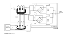
図7は、本変形例における無線電力伝送システム1の概略図の一例である。本変形例では、図1のキャパシタンス22aに代えて、高域阻止フィルタ(LPF)を設けている。このとき、第1受電回路20aは、第1受電コイル21aと接続されたLPF13bと、LPF13bの両端に接続された整流回路23aとを備える。
(First Modification)
Fig. 7 is an example of a schematic diagram of a wireless power transmission system 1 in this modification. In this modification, a high-pass filter (LPF) is provided instead of the
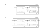
図8は、LPF13bの概略図の一例である。本明細書では、図8に示すLPF13bを例として、受電回路20に用いられるLPF13bを説明する。LPF13bは、キャパシタンス3とインダクタ26bとを含む。図8(a)に示すLPF13bは、1つのキャパシタンス3と4つのインダクタ26bとを含む。このようなLPF13bはLPF自体が小型であることに加えて、LPF13bを構成する素子のうち、受電コイル21と直列に接続されるインダクタ26bが、受電コイル21のインダクタンス成分を補完することにより、受電コイル21の巻き数を低減させることができるため、受電コイル21をより小型にすることが可能である。従って、このようなLPF13bを用いることにより、受電装置3を小型化することが可能である。一方、図8(b)に示すLPF13bは、複数のキャパシタンスを含む。並列キャパシタンスを複数設けるLPFの方が不要波を低減させる効果が高いため、整流回路23aにおける不要波の発生レベルが比較的高い場合は、図8(b)に示すようなLPFを用いても良い。ここで図示したLPF13b実施形態は、本変形例における受電回路20に含まれるLPFの一例であり、LPFの構成を限定するものではない。本変形例におけるLPFは、整流回路等において発生する高調波などの不要波受電コイルを低減することが可能な回路であればよい。なお、LPF13bには、送電装置2に含まれるLPF13aとは異なる種類のLPFを用いてもよい。
Figure 8 is an example of a schematic diagram of the
(第2の実施形態)
本実施形態では、第1の実施形態と同一部分には同一符号を付して説明を省略し、以下異なる部分について説明する。本実施形態では、無線電力伝送システム1を移動体のワイヤレス給電に用いる。そこで、本実施形態では、受電装置3と、受電装置3の電流を出力する出力部に接続された負荷4と、を備える移動体5について説明する。本実施形態では、移動体5の一例としてドローン300を用い、負荷4の一例として二次電池を用いて説明する。ドローンの放電時電流は、二次電池の電流容量Cに対して、10倍を超えることがあるため、ドローン300に搭載される二次電池の充電時の許容電流も、Cに対して10倍を超えるものが望まれる。従って、本実施形態のように、電気的に並列接続された複数の受電コイル21で受電した電力の出力電流を加算して、ドローン300に搭載された二次電池を大電流で充電することが望ましい。
Second Embodiment
In this embodiment, the same parts as those in the first embodiment are denoted by the same reference numerals and the description thereof is omitted, and the following description focuses on the different parts. In this embodiment, the wireless power transmission system 1 is used for wireless power supply to a moving body. In this embodiment, a moving
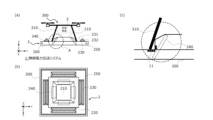
図9は、本実施形態における無線電力伝送システム1の概略図の一例である。図9(a)は駐機時のドローン300と送電装置2との側面図、図9(b)は送電装置2の上面図、図9(c)は図9(a)におけるA部内部の構造を示す拡大図である。送電装置2は、ドローンポート等のポートに設置されている。
Figure 9 is an example of a schematic diagram of a wireless power transmission system 1 in this embodiment. Figure 9(a) is a side view of the
図9(a)、図10(a)に示すように、無線電力伝送システム1は、移動体5(本実施形態ではドローン300を例として記載)と、移動体5に含まれる受電装置3へ向けて無線電力を送電する送電装置2と、を備える。また、移動体5(ここではドローン300)は、第1脚部310と第2脚部320とを含む脚部と、回転翼330と、を備える。第2脚部320は、送電面に対向する向きに配置され、環状である。回転翼330は、受電装置3が受電した電力により動作可能である。コイルユニット21uの少なくとも一部は第2脚部320に沿って設けられる。例えば、第2脚部320が中空状であり、コイルユニット21uの環状に巻回された部分が第2脚部320の内部に収められていればよい。あるいは、コイルユニット21uの環状に巻回された部分が第2脚部320の表面に沿って配置されていてもよい。ドローン300は、回転翼330により飛行可能である。
9(a) and 10(a), the wireless power transmission system 1 includes a moving body 5 (a
図9(b)に示すように、本実施形態における送電装置2は、送電コイル11を格納する筐体200を備える。筐体200は、錐体210と、着陸面220と、リム230とを備え、これらによる筐体200の形状の起伏によりドローン300の着陸面220への載置を誘導することが可能である。錐体210は、Z軸負の方向に向かって外側形状が大きくなる。図9(a)(b)では、錐体210は、正方形錐台が直方体の上に載る形状であるとして図示しているが、錐体210の形状はこれに限定されない。錐体210は、基本形状に対して角や辺が丸みを帯びていてもよい。錐体210の上側の形状は、上から下に広がるスロープになっている。錐体210は、一例として、非金属材料(例えばカーボン、プラスチック、カーボン及びプラスチックの混合、ガラス、ガラス繊維とプラスチックの混合、FRP等)により構成されている。錐体210の外側形状は、Z軸方向から見たときに、第2脚部320の内側形状と概ね相似であり、Z軸負の方向に向かって外側形状が大きくなる。このため、ドローンの着陸時、多少の水平方向の位置ずれ、角度ずれ、またはこれらの両方がある場合でも、第2脚部320の内側形状と錐体210の外側形状とが、自ら同じ向きになることにより、ドローンの着陸を安定させることができる。これにより第2脚部320が錐体210と嵌合し、ドローンは給電用の位置にセットされる。したがって、着陸の際、位置ずれ・角度ずれが生じにくくなる。なお、図中の錐体210は上部が開口しておらず、非金属材料で塞ぐ構成となっているが、開口していてもよい。
As shown in FIG. 9B, the
着陸面220は、ドローンが着陸する面を提供する。図9(a)に示すように、ドローンの第2脚部320が環状の着陸面220に着陸することで、ドローンを給電に適した位置に載置する。この際、錐体210の最下部に接する着陸面220の内側の形状が、第2脚部320の形状と概ね相似であることにより、第2脚部320が、所定の向きで、錐体210と嵌合する。概ね相似するとは、第2脚部320が錐体210に特定の方向で嵌合する程度に形状が近似していれば、完全な相似でなくてもよいことを意味する。また、特に、ドローンの中央からぶら下がる搭載物が金属を含む場合、送電装置2の近傍に生じる磁界が渦電流を発生させることがある。これによる電力伝送の効率の低下や発熱を防ぐため、錐体210の上部の少なくとも一部にアルミ板を配置しても良い。
The
リム230は、着陸面220に異物が混入することを防止する部材(防塵部材)である。例えば、着陸面220に混入した金属の異物は、給電の際に発熱する可能性がある。そのため、リム230を設けることにより、着陸面220への異物の混入を防止する必要がある。リム230は、図9(a)に示すように、例えば、側面(すなわち、垂直方向の断面)が三角形である三角柱である。あるいは、リム230は、側面が台形である四角柱、およびこれ以外の多角柱であってもよい。リム230は、着陸面220の外周に配置される。リム230は、Z方向に特定の高さを有する。この特定の高さは、例えば、錐体210の垂直方向の高さよりも高く設定されていてもよい。リム230は、例えば、錐体210に対向する面231(以下、前面231と称する)と、前面231と向かい合う面232(以下、背面232と称する)とを備える。前面308aは、例えば、Z軸負の方向に向かって錐体210の方向へ近づく傾きを有する。これにより、リム230は、ドローン300の第2脚部320がリム230の前面231に接することにより、第2脚部320を着陸面220のうちより給電に適した場所に誘導して、着陸面220上に正しく載置させるための誘導機構を有する。リム230の位置、高さ、および形状は、この誘導機構を実現するように設計され得る。これにより、ドローン300の送電装置2への着陸を容易にすることができる。なお、リム230の背面232は、着陸面220に対して垂直な面であってもよいし、傾きを有する面であってもよい。
The
本実施形態における送電装置2は、磁性体240と、ダミーループ250とを備える。
In this embodiment, the
磁性体240は、送電コイル11と受電コイル21との間の結合係数を向上させ、それにより、給電効率を向上させるための部材である。磁性体240は、例えば、フェライトである。磁性体240は、一定以上の透磁率を有するものを用いることが好ましい。磁性体240は、筒状あるいは筒の一部をおおよそ形作るように配置されている。図9(b)に示す磁性体240は、4つの磁性体240が一つの筒の一部をおおよそ形作るように配置されている例を示す。磁性体240は、Z軸正の方向に向かってすぼまった構造を有する筒状であることが好ましいが、複雑な形状の磁性体240は作製コストが嵩む。そこで、図9(b)(c)に示すように、平板状あるいは曲面を有する簡易的な形状の複数の磁性体240を、Z軸正の方向に向かうほど磁性体240どうしの距離が近くなるように傾けて配置してもよい。磁性体240は一例としてフェライトにより構成される。図中の磁性体240の一端は、着陸面220より下方の位置に固定しており、例えば筐体200の底面に接している。一方、磁性体240の他端は、錐体210の上部と概ね同じ高さに位置している。このように磁性体240を配置することにより、錐体210の高さを低く抑えることができる。これにより、ドローンの下部にカメラ用ジンバルなど大型の搭載物がある場合にも使用することができる。ただし、磁性体240の他端は、錐体210の上端より低くてもよい。また、磁性体240が厚いほど磁性特性は向上するが、製造コストも嵩む。そこで、磁性体240の部材の厚みは、送電コイル11に流す電流により発生する磁界が磁性体240を通過する際の磁束密度が、磁性体240の総断面積を勘案した飽和磁束密度を超えない程度の厚みであればよい。即ち、磁性体240の部材の厚みは、送電に使用する周波数に応じた表皮深さ(skin depth)よりもおおむね大きい厚みであればよい。これにより、磁界特性を犠牲にすることなく、軽量で低コスト化を図ることができる。また、磁性体240は筒状でなく、内部が磁性体材料あるいは非磁性体材料で埋められていても問題はない。磁性体240は、第2脚部320の内側及び受電コイル21の内側を貫通している。ただし、磁性体240は錐体210の内部に存在するのに対し、第2脚部320及び受電コイル21は錐体210の外部に存在する。受電コイル21と送電コイル11は同じ磁性体240の周囲を巻回した状態で、互いに第2脚部320を介して対向している。
The
また、送電装置2は、高周波の交流電流を出力可能な高周波発生回路10と、交流電流により磁束を発生可能な送電コイル11とを備える。コイルユニット21uと送電コイル11とが対向した状態において、送電コイル11が発生させた交番磁界によりコイルユニット21uに電流が流れる。図9(c)に示すように、送電コイル11は、送電装置2の筐体200の内部に配置されている。なお、送電コイル11は、少なくともその一部が着陸面220の下部に配置されている。これにより、コイルユニット21uと送電コイル11とは筐体200の着陸面220を介して対向して載置された状態において、送電コイル11が発生させた交番磁界によりコイルユニット21uに電流が流れる。即ち、ドローン300が送電装置2に着陸したとき、送電コイル11の少なくとも一部とコイルユニット21uの少なくとも一部とは、着陸面220を介して対向し、送電コイル11で生じた交番磁界により無線電力伝送を行うことができる。このとき、筐体200によるドローン300の載置の誘導や磁性体240による働きにより、受電コイル21が送電コイル11に高い結合係数で結合することができる。送電コイル11は、磁性体240の周囲を囲んでいる。これにより、送電コイル11の内側を、磁性体240が上下方向に貫通しているため、送電コイル11で発生する磁束が受電コイル21へと効率よく集約される。
The
ダミーループ250の材料は、銅などである。ダミーループ250には、送電コイル11で発生する交番磁界の一部が送電装置2の外側へ漏洩し、漏洩した磁界により誘導される電流が流れる。ダミーループ250に流れる電流により、漏洩した磁界を打ち消す方向の磁界が誘起され、送電装置2から遠方へ輻射する放射エミッションを低減することができる。
The material of the
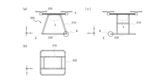
図10は、本実施形態におけるドローン300及びドローン300の脚部の概略図の一例である。図10(a)はドローン300の正面図、図10(b)はドローン300の脚部をZ軸方向から見た平面図、図10(c)はドローン300の側面図である。図10(a)に示すように、ドローン300は、第1脚部310と、第2脚部320と、受電装置3と、負荷4と、回転翼330とを備えている。
Figure 10 is an example of a schematic diagram of the
第1脚部310及び第2脚部320を含む本体フレームは、主として非金属材料(例えばカーボン、プラスチック、カーボン及びプラスチックの混合等)により構成されている。ただし、結合部やねじなどの一部が金属材料で構成されていてもよい。第1脚部310及び第2脚部320の内部は中空であることが好ましい。第1脚部310及び第2脚部320の内部が中空であることにより、ドローン300を軽量化できる。ただし、第1脚部310及び第2脚部320の内部は必ずしも中空でなくともよい。第1脚部310及び第2脚部320は、非金属材料(例えばカーボン、プラスチック、カーボン及びプラスチックの混合等)により構成されていることが好ましい。ただし、第1脚部310及び第2脚部320に非金属材料以外の材料が含まれていてもよい。第2脚部320は本体の最下部にあり、着陸する際に着陸面に接する。第2脚部320の内部には受電コイル21が設けられている。ドローン300の着陸が完了すると、第2脚部320の内部に配置された送電コイル11と受電コイル21とが概ね対峙する。これにより、送電コイル11に交番電流を流すことで、受電コイル21に誘電起電力が生じて電力伝送が行われる。
The main body frame including the
第2脚部320は環状である。図10の例では、第2脚部320はおおむね正方形である。しかし、第2脚部320の形状は必ずしも正方形に近い形でなくともよい。ドローン300の着陸時に第2脚部320が錐体210と嵌合すればよいので、錐体210の外側の形状および着陸面220の内側の形状が、第2脚部320の形状と概ね相似であればよい。例えば、錐体210の外側の形状および着陸面220の内側の形状が円形である場合、第2脚部320も円形であればよい。
The
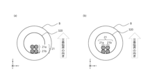
第2脚部320の内部には、2つの受電コイル21a、 21bを必要な巻回数通す。図11は、図10に示すB部の断面の拡大図である。図11において、受電コイル21の巻回数が2回の場合を示している。図11(a)に示すように2つの受電コイル21a、21bを交番磁界と同じ方向に積み上げることにより、2本の受電コイル21に印加される磁束の差が小さくなり、受電出力の差を低減することが可能となる。ただし、受電コイル21の位置関係はこれに限定されない。例えば、無線電力伝送に用いる周波数において、磁性体240における電力損失(いわゆる鉄損)が比較的大きい場合は、2つの受電コイル21a、21bを交番磁界と同じ方向(Z軸方向)に積み上げると、磁性体240からの影響を受けて受電コイルに生じる鉄損の大きさが受電コイルどうしで異なることがある。特に、磁性体240と受電コイル21との距離が2つの受電コイル21a、21bどうしで大きく異なる場合、磁性体240からの影響を受けて受電コイルに生じる鉄損の大きさの差も大きくなる。この場合は、図11(b)に示すように、2本のリッツ線を交番磁界の向きに直交する平面内(XY平面内)に並べることにより、各リッツ線が受電する電力の差をより小さくしてもよい。2つの受電コイル21a、21bの各両端は、第1脚部310の内部を経由し、ドローン300が備える受電回路20へ接続される。ここで、2つの受電コイル21a、21bの位置関係を「交番磁界と同じ方向に積み上げる」または「交番磁界の向きに直交する平面内に並べる」と表記したが、これらは一例であり、2つの受電コイル21a、21bの位置関係はこれらに限定されない。例えば、2つの受電コイル21a、21bはZ軸と完全に平行に積み上げられなくともよく、2つの受電コイル21a、21bがZ軸方向の位置が異なった状態であればよい。また、2つの受電コイル21a、21bが完全に交番磁界の向きに直交する平面内に配置されなくともよく、2つの受電コイル21a、21bを含む平面又は曲面が交番磁界におおよそ直交すればよい。また、図11では巻回数が2回、受電コイル21が2本の場合を図示したが、巻回数、受電コイル21の本数ともに、これに限定されない。
Inside the
また、振動等により、第1脚部310および第2脚部320の内部で受電コイル21が過度に動き、受電コイル21が損傷するのを防止するため、第2脚部320の内部を、軽量の発泡体、スポンジ、樹脂材料等で充填し、受電コイル21の過度な動きを防止してもよい。負荷4は、受電した電力を消費する機器等、または二次電池などの蓄電装置である。受電した電力を消費する機器の例として、ドローン300の回転翼330を駆動するモーター、モーターの駆動を制御する制御装置、または移動を制御するコンピュータ等がある。また、負荷4が二次電池である場合、リチウムイオン電池などの繰り返し使用可能な電池である。
In addition, in order to prevent excessive movement of the
回転翼330は、負荷4としてドローン300に搭載されたモーターにより駆動される。
The
このように、受電電力のほぼ等しい受電回路20が並列接続された受電装置3を含む無線電力伝送システム1をドローン等の移動体の給電に用いることにより、ドローン300に大電流でのワイヤレス給電を行うことが可能となる。
In this way, by using a wireless power transmission system 1 including a
さらに、本実施形態に示すように磁性体240を配置することにより、送電コイル11で発生した交番磁界により生ずる磁束のうち、多くの磁束は、磁性体240を通過する。これにより、磁束が高効率で受電コイル21に印加され、無線電力伝送の高効率化を図ることができる。
Furthermore, by arranging the
ただし、受電装置3の実施形態は、上述の内容に限定されない。例えば、受電コイル21は、必ずしも第2脚部320の内部に設けられなくともよい。任意の形状のドローン300の脚部の最下部に近い位置に設けられ、ドローン300の駐機時に送電コイル11と対峙できる箇所に配置されていればよい。
However, the embodiment of the
(第3の実施形態)
本実施形態では、無線電力伝送システム1を移動体5のワイヤレス給電に用いた例を示す。本実施形態において、移動体5とは、例えば、AGV(自動搬送車)などの産業用車両、電気自動車、電動バス等を含む車であるとして説明する。これらの移動体5は、高電圧でモーターを駆動する場合が多く、消費電力も多い。そのため、消費電流も大きくなる。したがって、大電流で急速に充電することが望まれる。そこで、本実施形態のように、複数の受電回路20を並列接続し、それらの出力電流を加算して、大電流を二次電池に供給することが考えられる。
Third Embodiment
In this embodiment, an example is shown in which the wireless power transmission system 1 is used for wireless power supply to a moving
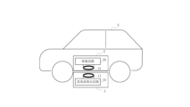
図12は、無線電力伝送システム1を移動体5のワイヤレス給電に用いる場合の概略図の一例である。本実施形態における無線電力伝送システム1は、移動体5と、受電装置3へ向けて無線電力を送電する送電装置2と、を備える。送電装置2は、高周波の交流電流を出力可能な高周波発生回路10と、交流電流により交番磁界を発生可能な送電コイル11と、を備える。コイルユニット21uと送電コイル11とが対向した状態において、交番磁界によりコイルユニット21uに電流が流れる。図12に示すように、図中の送電コイル11及び受電コイル21は、それぞれコイル面が床面に対して略平行になるように配置されている。しかし、無線電力伝送システム1の配置はこれに限定されない。例えば、送電装置2は、床面に垂直な壁面に保持されるように配置されていてもよいし、受電装置3は移動体の側面、進行方向前方、または進行方向後方に配置されていてもよい。
12 is an example of a schematic diagram of a case where the wireless power transmission system 1 is used for wireless power supply to a moving
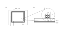
図13は、本実施形態において受電装置3が備える受電コイル21周辺の概略図の一例である。ここでは、移動体5の車体が金属を含む場合を例に説明する。本実施形態における移動体5はコイルユニット21uを備え、移動体5の車体とコイルユニット21uとの間にアルミを含む第1板材500を備え、アルミを含む板材500とコイルユニット21uとの間に磁性体を含む第2板材510を備える。移動体5は、車体の金属による影響を低減するために、磁気シールド効果のある第1板材500を移動体5の筐体側に設け、磁束を周囲になるべく逃がさないための第2板材510を第1板材500とコイルユニット21uとの間に設ける。第2板材510の好適例として、フェライトブロックが挙げられる。図13(a)は、移動体に搭載される受電装置3が備えるコイルユニット21u周辺の概略図の一例である。図13(a)において、送電コイル11で発生する交番磁界は図面手前から奥側、あるいは奥側から手前に向けて印加される。図13(a)において、コイルユニット21uは、複数の受電コイル21を含むが、これらの複数のコイルは交番磁界と同じ方向(Z軸方向)に積み上げられているため、交番磁界の方向から見ると重なって一つの受電コイルに見える場合を示している。図13(b)は、図13(a)のC部の断面の拡大図である。図13(b)に示すように、複数の受電コイル21(第1受電コイル21a、第2受電コイル21b)は、交番磁界と同じ方向(Z軸方向)に積み上げられている。図13(b)では受電コイル21の巻回数は3回の場合を示している。交番磁界と同じ方向に積み上げられることにより、各受電コイル21に印加される磁束の密度、振幅、および位相がほぼ等しくなるため、各受電コイル21に接続された受電回路20に流れる電流の振幅および位相に違いが生じない。ただし、第1受電コイル21aと第2受電コイル21bとの位置関係はこれに限定されない。例えば、無線電力伝送に用いる周波数において、第2板材510における電力損失(いわゆる鉄損)が比較的大きい場合は、図13(b)のように2つの受電コイル21a、21bを交番磁界と同じ方向に積み上げると、磁性体240からの影響を受けて、第1受電コイル21aと第2受電コイル21bとでコイルに生じる鉄損の大きさが異なることがある。特に、磁性体240と受電コイル21との距離が2つ受電コイル21どうしで大きく異なる場合、磁性体240からの影響を受けて受電コイル21に生じる鉄損の大きさの差も大きくなる。この場合は、2つの受電コイル21を交番磁界の向きに直交する平面内に並べることにより、各受電コイル21が受電する電力の差をより小さくしてもよい。このように、受電電力のほぼ等しい受電回路20が並列接続された受電装置3を含む無線電力伝送システム1をAGV等の移動体の給電に用いることにより、移動体に大電流での無線電力伝送を行うことが可能となる。
Figure 13 is an example of a schematic diagram of the periphery of the
ただし、受電装置3の実施形態は、上述の内容に限定されない。例えば、受電コイル21と整流回路23aとの間にはLPFやキャパシタンスが含まれていなくともよい。受電コイル21の形状や周波数、送電コイル11と受電コイル21との間の結合係数などの条件によっては、受電コイル21の有するキャパシタンスも含めて勘案すると、受電コイル21と整流回路23aの間に回路を設けなくともよい場合がある。
However, the embodiment of the
また、第1受電コイル21a、第2受電コイル21bは樹脂パイプ内に配置されてもよい。また、振動等により、樹脂パイプの内部で受電コイル21が過度に動き、受電コイル21が損傷するのを防止するため、樹脂パイプの内部を、軽量の発泡体、スポンジ、樹脂材料等で充填し、受電コイル21の過度な動きを防止してもよい。
The
本発明のいくつかの実施形態を説明したが、これらの実施形態は、例として提示したものであり、発明の範囲を限定することは意図していない。これら新規な実施形態は、その他の様々な形態で実施されることが可能であり、発明の要旨を逸脱しない範囲で、種々の省略、置き換え、変更、構成要素の組み合わせを行うことができる。これら実施形態やその変形は、発明の範囲や要旨に含まれるとともに、特許請求の範囲に記載された発明とその均等の範囲に含まれる。 Although several embodiments of the present invention have been described, these embodiments are presented as examples and are not intended to limit the scope of the invention. These novel embodiments can be implemented in various other forms, and various omissions, substitutions, modifications, and combinations of components can be made without departing from the gist of the invention. These embodiments and their modifications are included in the scope and gist of the invention, and are included in the scope of the invention and its equivalents as set forth in the claims.
更に、本開示は、以下の付記による例を含む。 Furthermore, this disclosure includes examples with the following appendices:
[付記1]
第1受電コイルと、
第2受電コイルと、
前記第1受電コイルに接続された第1受電回路と、
前記第2受電コイルに接続された第2受電回路と、
前記第1受電回路及び前記第2受電回路が出力した電流を電流加算する加算部と、
を備え、
前記第1コイルの軸に対して垂直な前記第1コイルの断面である第1受電面と、前記第2コイルの軸に対して垂直な前記第2コイル断面である第2受電面とを垂直に投影したとき、投影された前記第1受電面及び前記第2受電面は少なくとも一部が重複する、
受電装置。
[Appendix 1]
A first receiving coil;
A second power receiving coil;
A first power receiving circuit connected to the first power receiving coil;
A second power receiving circuit connected to the second power receiving coil;
an adder that adds currents output from the first power receiving circuit and the second power receiving circuit;
Equipped with
when a first power receiving surface, which is a cross section of the first coil perpendicular to an axis of the first coil, and a second power receiving surface, which is a cross section of the second coil perpendicular to an axis of the second coil, are projected perpendicularly, the projected first power receiving surface and the projected second power receiving surface at least partially overlap with each other.
Powered device.
[付記2]
前記第1受電面と前記第2受電面とを垂直に投影したとき、投影された前記第1受電面及び前記第2受電面は、前記第1受電面の面積の95%以上が重複する、
付記1に記載の受電装置。
[Appendix 2]
When the first power receiving surface and the second power receiving surface are vertically projected, 95% or more of an area of the first power receiving surface overlaps with the projected first power receiving surface and the projected second power receiving surface.
2. The power receiving device according to claim 1.
[付記3]
前記第1受電面の面積と前記第2受電面の面積とがほぼ等しい、
付記1又は2に記載の受電装置。
[Appendix 3]
The area of the first power receiving surface is approximately equal to the area of the second power receiving surface.
3. The power receiving device according to
[付記4]
前記第1受電回路は、前記第1受電コイルの両端に接続された整流回路を備える、
付記1乃至3のいずれか1つに記載の受電装置。
[Appendix 4]
The first power receiving circuit includes a rectifier circuit connected to both ends of the first power receiving coil.
4. The power receiving device according to claim 1 .
[付記5]
前記第1受電回路は、
前記第1受電コイルと並列接続されたキャパシタンスと、
前記キャパシタンスの両端に接続された整流回路と、
を備える、付記1乃至4のいずれか1つに記載の受電装置。
[Appendix 5]
The first power receiving circuit is
A capacitance connected in parallel with the first receiving coil;
a rectifier circuit connected across the capacitance;
5. The power receiving device according to claim 1, further comprising:
[付記6]
前記第1受電回路は、
一端が前記第1受電コイルの一端に直列接続されたキャパシタンスと、
前記第1受電コイルの他端と前記キャパシタンスの他端とに接続された整流回路と、
を備える、付記1乃至5のいずれか1つに記載の受電装置。
[Appendix 6]
The first power receiving circuit is
A capacitance having one end connected in series to one end of the first receiving coil;
a rectifier circuit connected to the other end of the first power receiving coil and the other end of the capacitance;
6. The power receiving device according to claim 1, further comprising:
[付記7]
前記第1受電回路は、
前記第1受電コイルと接続された高域阻止フィルタと、
前記高域阻止フィルタの両端に接続された整流回路と、
を備える、付記1乃至6のいずれか1つに記載の受電装置。
[Appendix 7]
The first power receiving circuit is
a high-pass filter connected to the first power receiving coil;
a rectifier circuit connected to both ends of the high-pass filter;
7. The power receiving device according to claim 1, further comprising:
[付記8]
前記第1受電回路は、
前記整流回路の両端に接続され、前記整流回路が出力した電流を平滑化可能な平滑回路を備える、付記4乃至7のいずれか1つに記載の受電装置。
[Appendix 8]
The first power receiving circuit is
8. The power receiving device according to
[付記9]
付記1乃至8のいずれか一項に記載の受電装置と、
前記受電装置の電流を出力する出力部に接続された負荷と、
を備える、移動体。
[Appendix 9]
A power receiving device according to any one of Supplementary Notes 1 to 8;
A load connected to an output section that outputs a current of the power receiving device;
A mobile body comprising:
[付記10]
環状の脚部と、
前記受電装置が受電した電力により動作可能な回転翼と、
を備え、
前記第1受電コイル及び前記第2受電コイルを含むコイルユニットの少なくとも一部は前記脚部に沿って設けられ、
前記回転翼により飛行可能である、
付記9に記載の移動体。
[Appendix 10]
A circular leg;
A rotor operable by the power received by the power receiving device;
Equipped with
At least a portion of a coil unit including the first power receiving coil and the second power receiving coil is provided along the leg portion,
The rotor is capable of flying,
10. The moving object according to claim 9.
[付記11]
前記移動体は車であり、
前記移動体の車体は金属を含み、
前記第1受電コイル及び前記第2受電コイルを含むコイルユニットを備え、
前記車体と前記コイルユニットとの間にアルミを含む第1板材を備え、
前記第1板材と前記コイルユニットとの間に磁性体を含む第2板材を備える、
付記9又は10に記載の移動体。
[Appendix 11]
The moving object is a car,
the vehicle body includes metal;
a coil unit including the first power receiving coil and the second power receiving coil,
a first plate material including aluminum is provided between the vehicle body and the coil unit;
a second plate member including a magnetic material is provided between the first plate member and the coil unit;
11. The moving object according to
[付記12]
付記1乃至8のいずれか一項に記載の受電装置と、
前記受電装置へ向けて無線電力を送電する送電装置と、
を備える、無線電力伝送システム。
[Appendix 12]
A power receiving device according to any one of Supplementary Notes 1 to 8;
a power transmitting device that transmits wireless power to the power receiving device;
A wireless power transmission system comprising:
[付記13]
前記送電装置は、
高周波の交流電流を出力可能な高周波発生回路と、
前記交流電流により交番磁界を発生可能な送電コイルと、
を備え、
前記第1受電コイル及び前記第2受電コイルを含むコイルユニットと前記送電コイルとが対向した状態において、
前記交番磁界により前記コイルユニットに電流が流れる、
付記12に記載の無線電力伝送システム。
[Appendix 13]
The power transmitting device is
A high frequency generating circuit capable of outputting a high frequency alternating current;
a power transmission coil capable of generating an alternating magnetic field by the alternating current;
Equipped with
In a state in which a coil unit including the first power receiving coil and the second power receiving coil faces the power transmitting coil,
The alternating magnetic field causes a current to flow in the coil unit.
13. The wireless power transmission system according to
[付記14]
付記9乃至11のいずれか1つに記載の移動体と、
前記受電装置へ向けて無線電力を送電する送電装置と、
を備え、
前記送電装置は、
高周波の交流電流を出力可能な高周波発生回路と、
前記交流電流により交番磁界を発生可能な送電コイルと、
を備え、
前記第1受電コイル及び前記第2受電コイルを含むコイルユニットと前記送電コイルとが対向した状態において、
前記交番磁界により前記コイルユニットに電流が流れる、
無線電力伝送システム。
[Appendix 14]
A moving object according to any one of Supplementary Notes 9 to 11,
a power transmitting device that transmits wireless power to the power receiving device;
Equipped with
The power transmitting device is
A high frequency generating circuit capable of outputting a high frequency alternating current;
a power transmission coil capable of generating an alternating magnetic field by the alternating current;
Equipped with
In a state in which a coil unit including the first power receiving coil and the second power receiving coil faces the power transmitting coil,
The alternating magnetic field causes a current to flow in the coil unit.
Wireless power transmission system.
[付記15]
付記9乃至11のいずれか1つに記載の移動体と、
前記受電装置へ向けて無線電力を送電する送電装置と、
を備え、
前記送電装置は、
高周波の交流電流を出力可能な高周波発生回路と、
前記交流電流により交番磁界を発生可能な送電コイルと、
前記送電コイルを格納する筐体と、
を備え、
前記筐体の形状の起伏により付記10に記載の移動体の載置を誘導可能であり、
前記第1受電コイル及び前記第2受電コイルを含むコイルユニットと前記送電コイルとが前記筐体を介して対向して載置された状態において、
前記交番磁界により前記コイルユニットに電流が流れる、
無線電力伝送システム。
[Appendix 15]
A moving object according to any one of Supplementary Notes 9 to 11,
a power transmitting device that transmits wireless power to the power receiving device;
Equipped with
The power transmitting device is
A high frequency generating circuit capable of outputting a high frequency alternating current;
a power transmission coil capable of generating an alternating magnetic field by the alternating current;
A housing for storing the power transmitting coil;
Equipped with
The housing has a shape that is undulating, and is capable of inducing placement of the moving body described in
In a state in which a coil unit including the first power receiving coil and the second power receiving coil and the power transmitting coil are placed opposite each other via the housing,
The alternating magnetic field causes a current to flow in the coil unit.
Wireless power transmission system.
[付記16]
無線電力伝送システムに含まれる受電装置が備えるコイルユニットであって、
第1受電コイル及び第2受電コイルを含み、
前記第1コイルの軸に対して垂直な前記第1コイルの断面である第1受電面と、前記第2コイルの軸に対して垂直な前記第2コイルの断面である第2受電面とを垂直に投影したとき、投影された前記第1受電面及び第2受電面は少なくとも一部が重複し、
前記第1受電コイルを流れる電流は、前記第1受電コイルに接続された第1受電回路に出力され、
前記第2受電コイルを流れる電流は、前記第2受電コイルに接続された第2受電回路に出力される、
コイルユニット。
[Appendix 16]
A coil unit provided in a power receiving device included in a wireless power transmission system,
A first receiving coil and a second receiving coil are included.
when a first power receiving surface, which is a cross section of the first coil perpendicular to an axis of the first coil, and a second power receiving surface, which is a cross section of the second coil perpendicular to an axis of the second coil, are vertically projected, the projected first power receiving surface and second power receiving surface at least partially overlap with each other,
The current flowing through the first receiving coil is output to a first receiving circuit connected to the first receiving coil,
The current flowing through the second power receiving coil is output to a second power receiving circuit connected to the second power receiving coil.
Coil unit.
1…無線電力伝送システム、2…送電装置、3…受電装置、4…負荷、5…移動体、10…高周波発生回路、11…送電コイル(一次コイル)、12…インバータ、13a,13b…LPF、20…受電回路、20a…第1受電回路、20b…第2受電回路、21…受電コイル(二次コイル)、21a…第1受電コイル、21b…第2受電コイル、21u…コイルユニット、21S…受電面、22a,22b,22c…キャパシタンス、23a,23b…整流回路、24…平滑回路、25…加算部、26a,26b…インダクタ、30…送電共振器、40…受電共振器、200…筐体、210…錐体、220…着陸面、230…リム、231…前面、232…背面、240…磁性体、250…ダミーループ、300…ドローン、310…第1脚部、320…第2脚部、330…回転翼、500…第1板材、510…第2板材 1...wireless power transmission system, 2...power transmission device, 3...power receiving device, 4...load, 5...mobile body, 10...high frequency generating circuit, 11...power transmission coil (primary coil), 12...inverter, 13a, 13b...LPF, 20...power receiving circuit, 20a...first power receiving circuit, 20b...second power receiving circuit, 21...power receiving coil (secondary coil), 21a...first power receiving coil, 21b...second power receiving coil, 21u...coil unit, 21S...power receiving surface, 22a, 22b, 2 2c...capacitance, 23a, 23b...rectifier circuit, 24...smoothing circuit, 25...adder, 26a, 26b...inductor, 30...power transmission resonator, 40...power reception resonator, 200...housing, 210...cone, 220...landing surface, 230...rim, 231...front, 232...back, 240...magnetic material, 250...dummy loop, 300...drone, 310...first leg, 320...second leg, 330...rotor, 500...first plate, 510...second plate
Claims (16)
第2受電コイルと、
前記第1受電コイルに接続された第1受電回路と、
前記第2受電コイルに接続された第2受電回路と、
前記第1受電回路及び前記第2受電回路が出力した電流を電流加算する加算部と、
を備え、
前記第1コイルの軸に対して垂直な前記第1コイルの断面である第1受電面と、前記第2コイルの軸に対して垂直な前記第2コイル断面である第2受電面とを垂直に投影したとき、投影された前記第1受電面及び前記第2受電面は少なくとも一部が重複する、
受電装置。 A first receiving coil;
A second power receiving coil;
A first power receiving circuit connected to the first power receiving coil;
A second power receiving circuit connected to the second power receiving coil;
an adder that adds currents output from the first power receiving circuit and the second power receiving circuit;
Equipped with
when a first power receiving surface, which is a cross section of the first coil perpendicular to an axis of the first coil, and a second power receiving surface, which is a cross section of the second coil perpendicular to an axis of the second coil, are projected perpendicularly, the projected first power receiving surface and the projected second power receiving surface at least partially overlap with each other.
Powered device.
請求項1に記載の受電装置。 When the first power receiving surface and the second power receiving surface are vertically projected, 95% or more of an area of the first power receiving surface overlaps with the projected first power receiving surface and the projected second power receiving surface.
The power receiving device according to claim 1 .
請求項1に記載の受電装置。 The area of the first power receiving surface is approximately equal to the area of the second power receiving surface.
The power receiving device according to claim 1 .
請求項1に記載の受電装置。 The first power receiving circuit includes a rectifier circuit connected to both ends of the first power receiving coil.
The power receiving device according to claim 1 .
前記第1受電コイルと並列接続されたキャパシタンスと、
前記キャパシタンスの両端に接続された整流回路と、
を備える、請求項1に記載の受電装置。 The first power receiving circuit is
A capacitance connected in parallel with the first receiving coil;
a rectifier circuit connected across the capacitance;
The power receiving device according to claim 1 .
一端が前記第1受電コイルの一端に直列接続されたキャパシタンスと、
前記第1受電コイルの他端と前記キャパシタンスの他端とに接続された整流回路と、
を備える、請求項1に記載の受電装置。 The first power receiving circuit is
A capacitance having one end connected in series to one end of the first receiving coil;
a rectifier circuit connected to the other end of the first power receiving coil and the other end of the capacitance;
The power receiving device according to claim 1 .
前記第1受電コイルと接続された高域阻止フィルタと、
前記高域阻止フィルタの両端に接続された整流回路と、
を備える、請求項1に記載の受電装置。 The first power receiving circuit is
a high-pass filter connected to the first power receiving coil;
a rectifier circuit connected to both ends of the high-pass filter;
The power receiving device according to claim 1 .
前記整流回路の両端に接続され、前記整流回路が出力した電流を平滑化可能な平滑回路を備える、請求項4に記載の受電装置。 The first power receiving circuit is
The power receiving device according to claim 4 , further comprising a smoothing circuit connected to both ends of the rectifier circuit and capable of smoothing a current output by the rectifier circuit.
前記受電装置の電流を出力する出力部に接続された負荷と、
を備える、移動体。 The power receiving device according to any one of claims 1 to 8,
A load connected to an output section that outputs a current of the power receiving device;
A mobile body comprising:
前記受電装置が受電した電力により動作可能な回転翼と、
を備え、
前記第1受電コイル及び前記第2受電コイルを含むコイルユニットの少なくとも一部は前記脚部に沿って設けられ、
前記回転翼により飛行可能である、
請求項9に記載の移動体。 A circular leg;
A rotor operable by the power received by the power receiving device;
Equipped with
At least a portion of a coil unit including the first power receiving coil and the second power receiving coil is provided along the leg portion,
The rotor is capable of flying,
The moving body according to claim 9.
前記移動体の車体は金属を含み、
前記第1受電コイル及び前記第2受電コイルを含むコイルユニットを備え、
前記車体と前記コイルユニットとの間にアルミを含む第1板材を備え、
前記第1板材と前記コイルユニットとの間に磁性体を含む第2板材を備える、
請求項9に記載の移動体。 The moving object is a car,
the vehicle body includes metal;
a coil unit including the first power receiving coil and the second power receiving coil,
a first plate material including aluminum is provided between the vehicle body and the coil unit;
a second plate member including a magnetic material is provided between the first plate member and the coil unit;
The moving body according to claim 9.
前記受電装置へ向けて無線電力を送電する送電装置と、
を備える、無線電力伝送システム。 The power receiving device according to any one of claims 1 to 8,
a power transmitting device that transmits wireless power to the power receiving device;
A wireless power transmission system comprising:
高周波の交流電流を出力可能な高周波発生回路と、
前記交流電流により交番磁界を発生可能な送電コイルと、
を備え、
前記第1受電コイル及び前記第2受電コイルを含むコイルユニットと前記送電コイルとが対向した状態において、
前記交番磁界により前記コイルユニットに電流が流れる、
請求項12に記載の無線電力伝送システム。 The power transmitting device is
A high frequency generating circuit capable of outputting a high frequency alternating current;
a power transmission coil capable of generating an alternating magnetic field by the alternating current;
Equipped with
In a state in which a coil unit including the first power receiving coil and the second power receiving coil faces the power transmitting coil,
The alternating magnetic field causes a current to flow in the coil unit.
The wireless power transmission system according to claim 12.
前記受電装置へ向けて無線電力を送電する送電装置と、
を備え、
前記送電装置は、
高周波の交流電流を出力可能な高周波発生回路と、
前記交流電流により交番磁界を発生可能な送電コイルと、
を備え、
前記第1受電コイル及び前記第2受電コイルを含むコイルユニットと前記送電コイルとが対向した状態において、
前記交番磁界により前記コイルユニットに電流が流れる、
無線電力伝送システム。 A moving body according to claim 10 or 11;
a power transmitting device that transmits wireless power to the power receiving device;
Equipped with
The power transmitting device is
A high frequency generating circuit capable of outputting a high frequency alternating current;
a power transmission coil capable of generating an alternating magnetic field by the alternating current;
Equipped with
In a state in which a coil unit including the first power receiving coil and the second power receiving coil faces the power transmitting coil,
The alternating magnetic field causes a current to flow in the coil unit.
Wireless power transmission system.
前記受電装置へ向けて無線電力を送電する送電装置と、
を備え、
前記送電装置は、
高周波の交流電流を出力可能な高周波発生回路と、
前記交流電流により交番磁界を発生可能な送電コイルと、
前記送電コイルを格納する筐体と、
を備え、
前記筐体の形状の起伏により請求項10に記載の移動体の載置を誘導可能であり、
前記第1受電コイル及び前記第2受電コイルを含むコイルユニットと前記送電コイルとが前記筐体を介して対向して載置された状態において、
前記交番磁界により前記コイルユニットに電流が流れる、
無線電力伝送システム。 A moving body according to claim 10;
a power transmitting device that transmits wireless power to the power receiving device;
Equipped with
The power transmitting device is
A high frequency generating circuit capable of outputting a high frequency alternating current;
a power transmission coil capable of generating an alternating magnetic field by the alternating current;
A housing for storing the power transmitting coil;
Equipped with
The housing has a shape that is undulating, and is capable of inducing placement of the moving body according to claim 10;
In a state in which a coil unit including the first power receiving coil and the second power receiving coil and the power transmitting coil are placed opposite each other via the housing,
The alternating magnetic field causes a current to flow in the coil unit.
Wireless power transmission system.
第1受電コイル及び第2受電コイルを含み、
前記第1コイルの軸に対して垂直な前記第1コイルの断面である第1受電面と、前記第2コイルの軸に対して垂直な前記第2コイルの断面である第2受電面とを垂直に投影したとき、投影された前記第1受電面及び第2受電面は少なくとも一部が重複し、
前記第1受電コイルを流れる電流は、前記第1受電コイルに接続された第1受電回路に出力され、
前記第2受電コイルを流れる電流は、前記第2受電コイルに接続された第2受電回路に出力される、
コイルユニット。 A coil unit provided in a power receiving device included in a wireless power transmission system,
A first receiving coil and a second receiving coil are included.
when a first power receiving surface, which is a cross section of the first coil perpendicular to an axis of the first coil, and a second power receiving surface, which is a cross section of the second coil perpendicular to an axis of the second coil, are vertically projected, the projected first power receiving surface and second power receiving surface at least partially overlap with each other,
The current flowing through the first receiving coil is output to a first receiving circuit connected to the first receiving coil,
The current flowing through the second power receiving coil is output to a second power receiving circuit connected to the second power receiving coil.
Coil unit.
Priority Applications (1)
| Application Number | Priority Date | Filing Date | Title |
|---|---|---|---|
| JP2023148426A JP2025041247A (en) | 2023-09-13 | 2023-09-13 | Power receiving device, mobile object, wireless power transmission system, and coil unit |
Applications Claiming Priority (1)
| Application Number | Priority Date | Filing Date | Title |
|---|---|---|---|
| JP2023148426A JP2025041247A (en) | 2023-09-13 | 2023-09-13 | Power receiving device, mobile object, wireless power transmission system, and coil unit |
Publications (1)
| Publication Number | Publication Date |
|---|---|
| JP2025041247A true JP2025041247A (en) | 2025-03-26 |
Family
ID=95105071
Family Applications (1)
| Application Number | Title | Priority Date | Filing Date |
|---|---|---|---|
| JP2023148426A Pending JP2025041247A (en) | 2023-09-13 | 2023-09-13 | Power receiving device, mobile object, wireless power transmission system, and coil unit |
Country Status (1)
| Country | Link |
|---|---|
| JP (1) | JP2025041247A (en) |
Citations (10)
| Publication number | Priority date | Publication date | Assignee | Title |
|---|---|---|---|---|
| JP2012060812A (en) * | 2010-09-10 | 2012-03-22 | Toko Inc | Non-contact power transmission device |
| JP2012205379A (en) * | 2011-03-25 | 2012-10-22 | Sanyo Electric Co Ltd | Charging system, power supply device, mobile body, wireless power transmission and reception system, and power reception device |
| JP2013535841A (en) * | 2010-08-06 | 2013-09-12 | オークランド ユニサービシズ リミテッド | Inductive power receiver device |
| WO2017042904A1 (en) * | 2015-09-09 | 2017-03-16 | 株式会社 東芝 | Wireless electric power delivery system, power transmitter, and power receiver |
| JP2017093182A (en) * | 2015-11-11 | 2017-05-25 | 株式会社ダイヘン | Non-contact power transmission system |
| JP2017135880A (en) * | 2016-01-28 | 2017-08-03 | 日立マクセル株式会社 | Wireless power supply system |
| WO2018225757A1 (en) * | 2017-06-07 | 2018-12-13 | 日本電産株式会社 | Unmanned aerial vehicle, unmanned aerial vehicle system, and battery system |
| JP2019213267A (en) * | 2018-05-31 | 2019-12-12 | 株式会社Soken | Non-contact transmission apparatus |
| JP2021168340A (en) * | 2020-04-10 | 2021-10-21 | Tdk株式会社 | Coil unit, mobile body, power receiving device, and wireless power transmission system |
| JP2022158970A (en) * | 2021-03-31 | 2022-10-17 | オムロン株式会社 | Wireless charging system, transmission side charging device and reception side charging device |
-
2023
- 2023-09-13 JP JP2023148426A patent/JP2025041247A/en active Pending
Patent Citations (10)
| Publication number | Priority date | Publication date | Assignee | Title |
|---|---|---|---|---|
| JP2013535841A (en) * | 2010-08-06 | 2013-09-12 | オークランド ユニサービシズ リミテッド | Inductive power receiver device |
| JP2012060812A (en) * | 2010-09-10 | 2012-03-22 | Toko Inc | Non-contact power transmission device |
| JP2012205379A (en) * | 2011-03-25 | 2012-10-22 | Sanyo Electric Co Ltd | Charging system, power supply device, mobile body, wireless power transmission and reception system, and power reception device |
| WO2017042904A1 (en) * | 2015-09-09 | 2017-03-16 | 株式会社 東芝 | Wireless electric power delivery system, power transmitter, and power receiver |
| JP2017093182A (en) * | 2015-11-11 | 2017-05-25 | 株式会社ダイヘン | Non-contact power transmission system |
| JP2017135880A (en) * | 2016-01-28 | 2017-08-03 | 日立マクセル株式会社 | Wireless power supply system |
| WO2018225757A1 (en) * | 2017-06-07 | 2018-12-13 | 日本電産株式会社 | Unmanned aerial vehicle, unmanned aerial vehicle system, and battery system |
| JP2019213267A (en) * | 2018-05-31 | 2019-12-12 | 株式会社Soken | Non-contact transmission apparatus |
| JP2021168340A (en) * | 2020-04-10 | 2021-10-21 | Tdk株式会社 | Coil unit, mobile body, power receiving device, and wireless power transmission system |
| JP2022158970A (en) * | 2021-03-31 | 2022-10-17 | オムロン株式会社 | Wireless charging system, transmission side charging device and reception side charging device |
Similar Documents
| Publication | Publication Date | Title |
|---|---|---|
| Cai et al. | A 500-W wireless charging system with lightweight pick-up for unmanned aerial vehicles | |
| Choi et al. | Generalized active EMF cancel methods for wireless electric vehicles | |
| JP5759716B2 (en) | Wireless power transmission system | |
| JP6300106B2 (en) | Non-contact power transmission device | |
| CN104662774B (en) | Antenna unit | |
| US9892847B2 (en) | Method for forming magnetic field space | |
| US10199163B2 (en) | Ground-side coil unit | |
| US20120169135A1 (en) | Non-contact power feeding apparatus of magnetic resonance method | |
| JP2019193563A (en) | Device | |
| US20170170688A1 (en) | System for Inductive Wireless Power Transfer for Portable Devices | |
| JP2019201451A (en) | Power transmission device, mobile body and wireless power transmission device | |
| JP2017168522A (en) | Coil device | |
| JP6009920B2 (en) | Non-contact power receiving apparatus and vehicle including the same, non-contact power transmission apparatus, and non-contact power transmission system | |
| JP6168500B2 (en) | Wireless power transmission device, power transmission device, and power reception device | |
| US10836261B2 (en) | Inductor unit, wireless power transmission device, and electric vehicle | |
| JPWO2013111344A1 (en) | Power receiving apparatus, power transmission system, and power transmission method | |
| JP2020009972A (en) | Inductor unit, non-contact power supply system, and electric vehicle | |
| Song et al. | A high-efficiency wireless power transfer system for unmanned aerial vehicle considering carbon fiber body | |
| JP6866324B2 (en) | Inductor unit, contactless power supply system and electric vehicle | |
| JP6600607B2 (en) | Inductor unit, wireless power transmission device, electric vehicle, and charging facility | |
| JP5906457B2 (en) | Contactless power supply | |
| CN204230992U (en) | For the system of induction type Energy Transfer and the part of system | |
| JP2023128475A (en) | Coil module, wireless power transmission device, wireless power reception device and wireless power transmission system | |
| CN118288813A (en) | A magnetic coupling mechanism for wireless charging of drones | |
| JP2019030150A (en) | Power transmission unit |
Legal Events
| Date | Code | Title | Description |
|---|---|---|---|
| RD07 | Notification of extinguishment of power of attorney |
Free format text: JAPANESE INTERMEDIATE CODE: A7427 Effective date: 20240719 |
|
| RD07 | Notification of extinguishment of power of attorney |
Free format text: JAPANESE INTERMEDIATE CODE: A7427 Effective date: 20250110 |
|
| RD07 | Notification of extinguishment of power of attorney |
Free format text: JAPANESE INTERMEDIATE CODE: A7427 Effective date: 20250321 |
|
| A621 | Written request for application examination |
Free format text: JAPANESE INTERMEDIATE CODE: A621 Effective date: 20251125 |
|
| RD01 | Notification of change of attorney |
Free format text: JAPANESE INTERMEDIATE CODE: A7421 Effective date: 20260420 |
|
| A977 | Report on retrieval |
Free format text: JAPANESE INTERMEDIATE CODE: A971007 Effective date: 20260727 |
|
| A131 | Notification of reasons for refusal |
Free format text: JAPANESE INTERMEDIATE CODE: A131 Effective date: 20260804 |