JP2025041246A - Electrochemical device, sensor and sensor system - Google Patents
Electrochemical device, sensor and sensor system Download PDFInfo
- Publication number
- JP2025041246A JP2025041246A JP2023148425A JP2023148425A JP2025041246A JP 2025041246 A JP2025041246 A JP 2025041246A JP 2023148425 A JP2023148425 A JP 2023148425A JP 2023148425 A JP2023148425 A JP 2023148425A JP 2025041246 A JP2025041246 A JP 2025041246A
- Authority
- JP
- Japan
- Prior art keywords
- housing
- sensor
- electrochemical device
- electrochemical
- substrate
- Prior art date
- Legal status (The legal status is an assumption and is not a legal conclusion. Google has not performed a legal analysis and makes no representation as to the accuracy of the status listed.)
- Pending
Links
Images

Classifications
-
- G—PHYSICS
- G01—MEASURING; TESTING
- G01N—INVESTIGATING OR ANALYSING MATERIALS BY DETERMINING THEIR CHEMICAL OR PHYSICAL PROPERTIES
- G01N27/00—Investigating or analysing materials by the use of electric, electrochemical, or magnetic means
- G01N27/26—Investigating or analysing materials by the use of electric, electrochemical, or magnetic means by investigating electrochemical variables; by using electrolysis or electrophoresis
- G01N27/403—Cells and electrode assemblies
- G01N27/406—Cells and probes with solid electrolytes
- G01N27/407—Cells and probes with solid electrolytes for investigating or analysing gases
- G01N27/4073—Composition or fabrication of the solid electrolyte
- G01N27/4074—Composition or fabrication of the solid electrolyte for detection of gases other than oxygen
-
- G—PHYSICS
- G01—MEASURING; TESTING
- G01N—INVESTIGATING OR ANALYSING MATERIALS BY DETERMINING THEIR CHEMICAL OR PHYSICAL PROPERTIES
- G01N33/00—Investigating or analysing materials by specific methods not covered by groups G01N1/00 - G01N31/00
- G01N33/0004—Gaseous mixtures, e.g. polluted air
- G01N33/0009—General constructional details of gas analysers, e.g. portable test equipment
- G01N33/0027—General constructional details of gas analysers, e.g. portable test equipment concerning the detector
- G01N33/0036—General constructional details of gas analysers, e.g. portable test equipment concerning the detector specially adapted to detect a particular component
-
- H—ELECTRICITY
- H01—ELECTRIC ELEMENTS
- H01M—PROCESSES OR MEANS, e.g. BATTERIES, FOR THE DIRECT CONVERSION OF CHEMICAL ENERGY INTO ELECTRICAL ENERGY
- H01M10/00—Secondary cells; Manufacture thereof
- H01M10/42—Methods or arrangements for servicing or maintenance of secondary cells or secondary half-cells
- H01M10/48—Accumulators combined with arrangements for measuring, testing or indicating the condition of cells, e.g. the level or density of the electrolyte
-
- H—ELECTRICITY
- H01—ELECTRIC ELEMENTS
- H01M—PROCESSES OR MEANS, e.g. BATTERIES, FOR THE DIRECT CONVERSION OF CHEMICAL ENERGY INTO ELECTRICAL ENERGY
- H01M50/00—Constructional details or processes of manufacture of the non-active parts of electrochemical cells other than fuel cells, e.g. hybrid cells
- H01M50/20—Mountings; Secondary casings or frames; Racks, modules or packs; Suspension devices; Shock absorbers; Transport or carrying devices; Holders
- H01M50/289—Mountings; Secondary casings or frames; Racks, modules or packs; Suspension devices; Shock absorbers; Transport or carrying devices; Holders characterised by spacing elements or positioning means within frames, racks or packs
- H01M50/293—Mountings; Secondary casings or frames; Racks, modules or packs; Suspension devices; Shock absorbers; Transport or carrying devices; Holders characterised by spacing elements or positioning means within frames, racks or packs characterised by the material
-
- Y—GENERAL TAGGING OF NEW TECHNOLOGICAL DEVELOPMENTS; GENERAL TAGGING OF CROSS-SECTIONAL TECHNOLOGIES SPANNING OVER SEVERAL SECTIONS OF THE IPC; TECHNICAL SUBJECTS COVERED BY FORMER USPC CROSS-REFERENCE ART COLLECTIONS [XRACs] AND DIGESTS
- Y02—TECHNOLOGIES OR APPLICATIONS FOR MITIGATION OR ADAPTATION AGAINST CLIMATE CHANGE
- Y02E—REDUCTION OF GREENHOUSE GAS [GHG] EMISSIONS, RELATED TO ENERGY GENERATION, TRANSMISSION OR DISTRIBUTION
- Y02E60/00—Enabling technologies; Technologies with a potential or indirect contribution to GHG emissions mitigation
- Y02E60/10—Energy storage using batteries
Landscapes
- Chemical & Material Sciences (AREA)
- Health & Medical Sciences (AREA)
- Life Sciences & Earth Sciences (AREA)
- Engineering & Computer Science (AREA)
- Chemical Kinetics & Catalysis (AREA)
- Electrochemistry (AREA)
- Pathology (AREA)
- General Physics & Mathematics (AREA)
- Immunology (AREA)
- Physics & Mathematics (AREA)
- Analytical Chemistry (AREA)
- Biochemistry (AREA)
- General Health & Medical Sciences (AREA)
- General Chemical & Material Sciences (AREA)
- Molecular Biology (AREA)
- Combustion & Propulsion (AREA)
- Food Science & Technology (AREA)
- Medicinal Chemistry (AREA)
- Manufacturing & Machinery (AREA)
- Investigating Or Analyzing Materials By The Use Of Electric Means (AREA)
- Investigating Or Analyzing Materials By The Use Of Fluid Adsorption Or Reactions (AREA)
Abstract
【課題】センシング機能の低下を抑制する電気化学装置を提供すること。【解決手段】実施形態によれば、筐体と、筐体の内部に存在する第1の電気化学素子と、筐体の内部の少なくとも一部を占める多孔質構造体と、を有する電気化学装置が提供される。【選択図】図1The present invention provides an electrochemical device that suppresses deterioration of a sensing function. According to an embodiment, an electrochemical device is provided that has a housing, a first electrochemical element present inside the housing, and a porous structure that occupies at least a part of the inside of the housing. (Selected Figure)
Description
本発明の実施形態は、電気化学装置、センサ及びセンサシステムに関する。 Embodiments of the present invention relate to electrochemical devices, sensors, and sensor systems.
例えば、酸素や水素をセンシングするセンサがある。このようなセンサにおいて、一般的に、設置される雰囲気中の蒸気やガス等にセンサが暴露されることで、センシング機能が低下してしまう。 For example, there are sensors that sense oxygen or hydrogen. In such sensors, the sensing function generally deteriorates when the sensor is exposed to steam or gas in the atmosphere in which it is installed.
本発明が解決しようとする課題は、センシング機能の低下を抑制する電気化学装置、センサ及びセンサシステムを提供することである。 The problem that the present invention aims to solve is to provide an electrochemical device, a sensor, and a sensor system that suppresses the deterioration of the sensing function.
実施形態によれば、筐体と、筐体の内部に存在する第1の電気化学素子と、筐体の内部の少なくとも一部を占める多孔質構造体と、を有する電気化学装置が提供される。 According to an embodiment, an electrochemical device is provided that has a housing, a first electrochemical element present inside the housing, and a porous structure that occupies at least a portion of the inside of the housing.
以下、実施形態について図面を参照しながら説明する。なお、以下の説明において、同一又は類似した機能を発揮する構成要素には全ての図面を通じて同一の参照符号を付し、重複する説明は省略する。なお、各図は実施形態の説明とその理解を促すための模式図であり、その形状や寸法、比などは実際の装置と異なる点があるが、これらは以下の説明と公知の技術を参酌して適宜設計変更することができる。 The following describes the embodiments with reference to the drawings. In the following description, components that perform the same or similar functions are given the same reference symbols throughout the drawings, and duplicate descriptions are omitted. Each figure is a schematic diagram to facilitate the explanation and understanding of the embodiments, and the shapes, dimensions, ratios, etc. may differ from the actual device, but these can be appropriately modified in design by taking into account the following explanation and known technology.
[第1の実施形態]
酸素や水素をセンシングするセンサは、汚染されることによってセンシング機能の低下や、センサが有するセンサ回路が故障してしまう虞がある。このセンサの汚染は、電気化学装置が設けられる雰囲気中の水分やガス等に暴露されることによって生じ得る。汚染の中でも例えば、水分(以後、総称して水蒸気とするが、態様は液体であっても気体であってもよい。)によるセンサの汚染を抑制するために、電気化学装置は除湿器のような電気化学素子を備える。
[First embodiment]
Sensors for sensing oxygen or hydrogen may be contaminated, which may result in a decrease in sensing function or a failure of the sensor circuitry of the sensor. This contamination of the sensor may occur due to exposure to moisture or gas in the atmosphere in which the electrochemical device is installed. In order to suppress the contamination of the sensor due to moisture (hereinafter collectively referred to as water vapor, which may be in the form of liquid or gas), the electrochemical device includes an electrochemical element such as a dehumidifier.
また、電気化学装置の有する筐体は元々水蒸気を含んでおり、センサの駆動による熱の発生等によって、筐体に含まれる水蒸気が筐体の内部に出てきてしまう。これによって、筐体の内部に設けられるセンサやセンサ回路は、水蒸気に長時間曝露されてしまい、センサ回路の故障やセンサのセンシング機能が低下してしまう。従って、センサやセンサ回路が水蒸気に長時間曝露されることを抑制し、センサのセンシング機能の低下やセンサが有するセンサ回路の故障を抑制することが必要である。 In addition, the housing of the electrochemical device originally contains water vapor, and the water vapor contained in the housing is released into the inside of the housing due to heat generation caused by the operation of the sensor, etc. This causes the sensor and sensor circuit installed inside the housing to be exposed to water vapor for a long period of time, causing the sensor circuit to break down and the sensor's sensing function to deteriorate. Therefore, it is necessary to prevent the sensor and sensor circuit from being exposed to water vapor for a long period of time, and to prevent the sensor's sensing function from being deteriorated and the sensor circuit in the sensor from breaking down.
そこで第1の実施形態によれば、筐体と、筐体の内部に存在する第1の電気化学素子と、筐体の内部の少なくとも一部を占める多孔質構造体と、を有する電気化学装置が提供される。 Therefore, according to the first embodiment, an electrochemical device is provided that has a housing, a first electrochemical element present inside the housing, and a porous structure that occupies at least a portion of the inside of the housing.
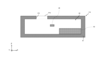
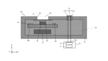
以下より、図面を用いて、センサにおけるセンシング機能の低下の抑制をする電気化学装置について説明する。図1は、第1の実施形態に係る電気化学装置を例示する模式的断面図である。図1において電気化学装置110は、筐体81と、筐体81の内部に存在する第1の電気化学素子46と、筐体81の内部の少なくとも一部を占める多孔質構造体82と、を有する。筐体81は、開口部81o及び貫通孔81tを有する。開口部81oは、貫通孔81tの入口又は出口に相当する。開口部の形状は、略四角形でも円形でもよく、形状は問わない。図1において、開口部81oの法線方向をZ軸方向とし、このZ軸方向に対して垂直な方向をX軸方向、Z軸及びX軸方向に対して垂直な方向をY軸とする。
The following describes an electrochemical device that suppresses the deterioration of the sensing function of a sensor, using the drawings. FIG. 1 is a schematic cross-sectional view illustrating an electrochemical device according to a first embodiment. In FIG. 1, the
多孔質構造体82は、筐体81の内部の少なくとも一部を占める。これによって、筐体81の内部の湿度が筐体81の外部より低く保たれている場合、例えば、60%以下である場合に、筐体81の内部に入り込む水蒸気を多孔質構造体82が取り込むことができる。これは、筐体81の内部に表面積の大きい多孔質構造体82が存在することで、筐体81の内部の実効的な容積を大きくすることができ、これによって、筐体81の内部の湿度を相対的に低くすることができる。
The
多孔質構造体82は筐体81の内壁の少なくとも一部を覆うことが好ましい。前述であることで、筐体81が元々含む水蒸気を多孔質構造体82が取り込むことができる。これによって、第1の電気化学素子46が水蒸気に長時間曝露されることを抑制することができる。より好ましくは、筐体81の内壁の全体を多孔質構造体82が覆うことである。
It is preferable that the
筐体81の内部に設けられる第1の電気化学素子46を除いた、多孔質構造体82の筐体の内部での充填率は10%以上100%以下であることが好ましい。
It is preferable that the filling rate of the
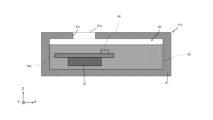
図2は、第1の実施形態に係る電気化学装置の他の一例を例示する模式的断面図である。図2において、電気化学装置110は、基板30sと、第1の電池31と、をさらに有し、第1の電気化学素子46は基板30s上に設けられ、第1の電池31は第1の電気化学素子46が設けられる面と反対側の基板30s上の面に設けられる。
Figure 2 is a schematic cross-sectional view illustrating another example of the electrochemical device according to the first embodiment. In Figure 2, the
第1の電池31は、マイクロコンピュータ(以下、マイコンという)回路が設けられる基板30sの面と対向する。また、マイコン回路が設けられる基板30sの面と反対側の第1の電気化学素子46が設けられる面では、センサ回路が設けられる。尚、上側にマイコン回路、下側にセンサ回路の構成の場合もある。
The
基板30sは、例えば、エポキシ樹脂、フェノール樹脂、ポリイミド樹脂、更にガラス布が含まれるガラスエポキシ樹脂のような樹脂を含んでよい。ここで前述のとおり、基板30sは、樹脂基板であり、空気に含まれる水蒸気を元々含む。この基板30sが元々含んでいる水蒸気は、センサ回路やマイコン回路等の駆動から生じる熱によって基板から放出されてしまうことから、前述した回路やセンサ等を汚染してしまう。従って、図2のように、基板30s上に生じ得る水蒸気を取り込むように多孔質構造体82が筐体81の内部に設けられていることが好ましい。
The
例えば、多孔質構造体82は、第1の電池31、基板30s、第1の電気化学素子46を実質的に覆うように構成されることが望ましい。
For example, it is desirable that the
また、多孔質構造体82は、第1の電池31を実質的に覆うように構成しても良い。
The
また、多孔質構造体82は、第1の電池31を実質的に覆い、基板30sの一部を覆うように構成しても良い。
The
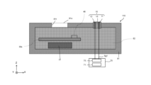
図3は、第1の実施形態に係る電気化学装置のさらに他の一例を例示する模式的断面図である。図3では、基板30sと第1の電池31との間に多孔質構造体82が存在する。多孔質構造体82は、基板30sと第1の電池31との間に存在することが好ましい。
Figure 3 is a schematic cross-sectional view illustrating yet another example of the electrochemical device according to the first embodiment. In Figure 3, a
第1の電池31が設けられる基板31sの面では、センサ回路やマイコン回路等の駆動から生じる熱に加えて、第1の電池31の作動による熱が伝わる。これによって、第1の電気化学素子46が設けられる基板30sの面と比べて、第1の電池31が設けられる基板31sの面からより多くの水蒸気が放出される。従って、図3のような構成であることで、多孔質構造体82が基板30s全体を覆い、基板30sから放出された水蒸気をより速やかに多孔質体構造体82で捉えられるため、周辺の湿度上昇を抑制することができる。
The surface of the substrate 31s on which the
また、基板30sと第1の電池31との間に多孔質構造体82が存在することで、第1の電池31は基板30sに物理的に接しないため、第1の電池31の駆動による熱が基板30sへ伝わることを抑制できる。これによって、基板30sの温度が上がることによる基板30sからの水蒸気の放出を抑制することができる。
In addition, because the
また、図3の電気化学装置110は、第2の電気化学素子10を有する。第2の電気化学素子10は、第1電極11と第2電極12及び部材15を含む。部材15は、第1電極11と第2電極12との間に設けられる。例えば、部材15は、高分子電解質を含む。
The
第2の電気化学素子10は、例えば、除湿、加湿、オゾン発生、酸素発生、酸素除去、及び、水素発生の少なくともいずれかが可能である。第1電極11と第2電極12との間に電圧が印加されることで、除湿、加湿、オゾン発生、酸素発生、酸素除去、及び、水素発生の少なくともいずれかが可能である。
The second
筐体81の内部に設けられる多孔質構造体82は第2の電気化学素子10の少なくとも一部を覆うことが好ましい。第2の電気化学素子10の一部が多孔質構造体82により覆われることで、部材15を通って筐体81の外部から内部への水蒸気の侵入を防ぐことができる。より好ましくは、第2の電気化学素子10の筐体81の内部に存在する部分全体が多孔質構造体82によって覆われることである。
It is preferable that the
以下では、第2の電気化学素子10が除湿の機能を有する例について説明する。第1電極11と第2電極12との間に電圧が印加されることで、除湿が行われる。例えば、電圧印加により、筐体81内の水分が電気化学分解により水素と酸素に分けられ、部材15を通して筐体81の外部へと放出される。これにより、除湿が行われる。電圧の印加は、例えば、電池を備え付けることにより行われる。
Below, an example will be described in which the second
例えば、第2電極12を基準にした電圧が、第1電極11に印加される。例えば、第1電極11に第1極性の電圧が印加されたときに、第2の電気化学素子10は、部材15を通して水を筐体81の外部へと放出する。以下では、第1極性を正とする。第1電極11に第1極性の電圧が印加されたときに、除湿が行われる。
For example, a voltage based on the
第2の電気化学素子10は、筐体81の中の空間85の水を部材15を通して筐体81の外部へと放出可能である。これにより、筐体81の中の空間が除湿される。
The second
電気化学装置110は、さらに制御部70を含むことができる。制御部70は、第1電極11及び第2電極12と電気的に接続される。この例では、制御部70は、回路部75及び第2の電池71を含む。第2の電池71は回路部75に電力を供給可能である。回路部75は、第1電極11と第2電極12との間に電圧を印加可能である。電圧は、例えば、第1信号Sg1である。第1信号Sg1(電圧)が第1電極11及び第2電極12に印加されることで、第2の電気化学素子10における電気化学作用(例えば除湿)が行われる。
The
実施形態において、電気化学装置110は、第2の電池71で駆動される。これにより、商業電力などが供給されない場所での動作が可能になり、電気化学装置110及びそれを用いた各種の機器の用途が拡大する。第2の電池71の容量は定まっていることから、電気化学装置110の駆動時間を長くするためには、電気化学装置110において消費電力の低減が望まれる。
In the embodiment, the
一般に、第2の電気化学素子10は、値が一定の直流信号(直流電圧)で駆動されることが多い。この場合、第2の電気化学素子10において、値が一定の直流電流が流れる。これにより、常に電力が消費され、これにより、消費電力が増大する。
In general, the second
実施形態においては、第2の電気化学素子10に供給される電圧(第1信号Sg1)は、デューティ信号とされる。このとき、第1信号Sg1を特殊な波形とすることで、高い電気化学作用を維持しつつ消費電力を低減できる。その理由については、図4を用いて後述する。
In this embodiment, the voltage (first signal Sg1) supplied to the second
実施形態において、第2の電気化学素子10は、陰極及び陽極を含む。陰極は、第1電極11及び第2電極12の一方である。陽極は、第1電極11及び第2電極12の他方である。
In the embodiment, the second
例えば、陰極は、陰極基体と、陰極基体の表面に設けられた陰極側触媒部材と、を含んで良い。陽極は、陽極基体と、陽極基体の表面に設けられた陽極側触媒部材と、を含んで良い。陰極側触媒部材と陽極側触媒部材との間に、固体高分子電解質膜の少なくとも一部が設けられる。固体高分子電解質膜は、部材15に対応する。
For example, the cathode may include a cathode substrate and a cathode-side catalytic member provided on the surface of the cathode substrate. The anode may include an anode substrate and an anode-side catalytic member provided on the surface of the anode substrate. At least a portion of a solid polymer electrolyte membrane is provided between the cathode-side catalytic member and the anode-side catalytic member. The solid polymer electrolyte membrane corresponds to
例えば、陰極基体は、カーボン膜(例えばカーボンペーパ)を含む。陰極側触媒部材は、カーボン粉末を含む。カーボン粉末の表面に白金が付着している。カーボン粉末は、白金を保持する。例えば、陽極基体は、チタンメッシュを含む。チタンメッシュの表面に、白金膜が設けられる。白金膜は、例えば、めっき処理により形成される。陽極側触媒部材は、白金粒子及びフッ素樹脂を含む。固体高分子電解質膜は、フッ素樹脂を含む。フッ素樹脂は、例えば、スルホ化されたテトラフルオロエチレンを基にしたフッ素樹脂の共重合体である。 For example, the cathode substrate includes a carbon film (e.g., carbon paper). The cathode side catalyst member includes carbon powder. Platinum is attached to the surface of the carbon powder. The carbon powder holds the platinum. For example, the anode substrate includes a titanium mesh. A platinum film is provided on the surface of the titanium mesh. The platinum film is formed, for example, by a plating process. The anode side catalyst member includes platinum particles and a fluororesin. The solid polymer electrolyte membrane includes a fluororesin. The fluororesin is, for example, a fluororesin copolymer based on sulfonated tetrafluoroethylene.
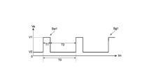
次に、図4を用いて第1信号Sg1の例について説明する。図4は、第1信号Sg1を例示している。図4の横軸は、時間tmである。縦軸は、第1電極11と第2電極12との間の電圧Vaである。電圧Vaは、第2電極12の電位を基準とした電位である。
Next, an example of the first signal Sg1 will be described with reference to FIG. 4. FIG. 4 illustrates the first signal Sg1. The horizontal axis of FIG. 4 is time tm. The vertical axis is the voltage Va between the
図4に示すように、第1信号Sg1は、第1周期T0で繰り返す波形Sw1を含む。波形Sw1は、第1期間T1及び第2期間T2を含む。第1期間T1において、電圧Vaは、第1極性の第1電圧V1である。第2期間T2において、電圧Vaは、第1極性の第2電圧V2である。第1極性は、正または負のいずれかである。この例では、第1極性は正である。第1電圧V1及び第2電圧V2は、正である。第2電圧V2の絶対値は、第1電圧V1の絶対値よりも小さい。 As shown in FIG. 4, the first signal Sg1 includes a waveform Sw1 that repeats in a first period T0. The waveform Sw1 includes a first period T1 and a second period T2. In the first period T1, the voltage Va is a first voltage V1 of a first polarity. In the second period T2, the voltage Va is a second voltage V2 of a first polarity. The first polarity is either positive or negative. In this example, the first polarity is positive. The first voltage V1 and the second voltage V2 are positive. The absolute value of the second voltage V2 is smaller than the absolute value of the first voltage V1.
1つの例において、第1電圧V1は、2.5V以上3.5V以下である。1つの例において、第2電圧V2は、0.5V以上1.5V以下である。このように低電圧の第2電圧V2も第1極性(正)であり、0電圧ではないことで、高電圧(第1電圧V1)の第1期間T1から、低電圧(第2電圧V2)の第2期間T2への遷移期間に流れる電流が、負電流となり難くなる。前述した遷移期間に流れる電流は、正の電流であり、仮に遷移期間に流れる電流が負であったとしても、その絶対値は小さい。これにより、電気化学作用における逆の反応、即ち、部材15から筐体81の内部に水分が放出される反応が抑制される。また、低電圧の第2電圧V2の第2期間T2が設けられることにより、このような第1信号Sg1では、目的とする高い電気化学作用(例えば除湿)を維持しつつ、消費電力を低減できる。
In one example, the first voltage V1 is 2.5V or more and 3.5V or less. In one example, the second voltage V2 is 0.5V or more and 1.5V or less. Since the low second voltage V2 is also of the first polarity (positive) and is not 0 voltage, the current flowing during the transition period from the first period T1 of the high voltage (first voltage V1) to the second period T2 of the low voltage (second voltage V2) is unlikely to become negative. The current flowing during the transition period described above is a positive current, and even if the current flowing during the transition period is negative, its absolute value is small. This suppresses the reverse reaction in the electrochemical action, that is, the reaction in which moisture is released from the
多孔質構造体はゼオライト、シリカゲル、活性アルミナ、活性炭、多孔質ポリマーからなる群より選ばれる少なくとも1つであることが好ましいが、筐体の内部の実効的な容積を大きくすることができるものであれば前述の材料に限定されない。 The porous structure is preferably at least one selected from the group consisting of zeolite, silica gel, activated alumina, activated carbon, and porous polymer, but is not limited to the above materials as long as it can increase the effective internal volume of the housing.
筐体は、例えば、ゼオライト、活性炭、及びシリカゲルのような樹脂を含んでよい。 The housing may include, for example, a resin such as zeolite, activated carbon, and silica gel.
第1の実施形態に係る電気化学装置は、筐体と、筐体の内部に存在する第1の電気化学素子と、筐体の内部の少なくとも一部を占める多孔質構造体と、を有する。これによって、センシング機能の低下を抑制することができる。 The electrochemical device according to the first embodiment has a housing, a first electrochemical element present inside the housing, and a porous structure occupying at least a portion of the inside of the housing. This makes it possible to suppress deterioration of the sensing function.
[第2の実施形態]
第2の実施形態によれば、第1の実施形態に記載の電気化学装置と、筐体の内部に設けられた検出部と、を備えたセンサが提供される。
Second Embodiment
According to a second embodiment, there is provided a sensor including the electrochemical device according to the first embodiment and a detection unit provided inside a housing.
図5は、第2の実施形態に係るセンサを例示する模式的断面図である。図5に示すように、実施形態に係るセンサ210は、第1実施形態に係る電気化学装置110と、検出部30と、を含む。また、センサ210は、加えて、通信部45を含んでもよい。センサ210が含む検出部30及び通信部45について、基板30sの平面図及び断面図である図6を用いて後述する。
Figure 5 is a schematic cross-sectional view illustrating a sensor according to the second embodiment. As shown in Figure 5, the
実施形態において、第2の電気化学素子10と検出部30との間の距離は、短いことが好ましい。例えば、検出部30は、第2の電気化学素子10の近くに固定されることが好ましい。第2の電気化学素子10と検出部30との間の距離は、例えば、1mm以上50mm以下である。
In the embodiment, the distance between the second
図5では、センサ210は、第1膜41を含む。第1膜41は、検出部30と、筐体81の第1開口部81oと、の間に設けられる。第1膜41は、例えば、開口部81oをふさぐように設けられる。第1膜41の少なくとも一部は、ポーラスである。第1膜41は、例えば、フッ素を含む樹脂を含む。第1膜41は、例えば、PTFE(polytetrafluoroethylene)を含む。第1膜41は、例えば、液体(水など)を透過させない。第1膜41は、検出部30の検出対象の気体(例えば水素など)を透過させる。
In FIG. 5, the
実施形態において、第1膜41は検出部30と接して良い。または、第1膜41と検出部30との間の距離は、1cm以下である。第1膜41の近くに検出部30が設けられることで、第1膜41を通過した検出対象のガスをより高い精度で検出できる。
In an embodiment, the
第1膜41が開口部81oに設けられることで、筐体81の中の空間85において、外部の湿度の影響が抑制される。第2の電気化学素子10による電気化学的な作用(例えば除湿)により、空間85の状態が目的とする状態となる。後述するように、筐体81の中に検出部などが設けられることで、検出部の状態が目的とする状態(例えば低湿度)に維持できる。
By providing the
図5に示すように、センサ210は、第1の電池31を含んでも良い。第1の電池31は、検出部30に電力を供給可能である。第1の電池31が設けられることで、例えば、商業電力が供給されない場所においても、検出対象を検出できる。
As shown in FIG. 5, the
センサ210において、基板30sの上に検出部30が設けられる。センサ210において、検出部30は開口部81oと基板30sとの間に設けられる。検出部30と第1膜41との間に、蓋35が設けられても良い。蓋35は、穴を有していてもよい。基板30sの上に、湿度センサ46が設けられても良い。湿度センサ46により、筐体81の内部の空間85における湿度がモニタされて良い。
In the
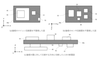
図6は、第1の実施形態に係る電気化学装置が備える基板を例示する模式的平面図及び模式的断面図である。図6(a)は、基板のマイコン回路が設けられる面を平面視したときの図である。図6(b)は、基板のセンサ回路が設けられている面を平面視したときの図である。図6(c)は、基板の面に対して交差する方向に切断したときの断面図である。 Figure 6 is a schematic plan view and a schematic cross-sectional view illustrating a substrate provided in the electrochemical device according to the first embodiment. Figure 6(a) is a plan view of the surface of the substrate on which the microcomputer circuit is provided. Figure 6(b) is a plan view of the surface of the substrate on which the sensor circuit is provided. Figure 6(c) is a cross-sectional view taken in a direction intersecting the surface of the substrate.
図6において、基板30sのマイコン回路面からセンサ回路面に向かう向きをZ軸方向とし、Z軸方向と交差する方向をX軸方向、Y軸方向と図6(a)のとおり定義する。
In FIG. 6, the direction from the microcomputer circuit surface of the
基板30sは、マイコン回路51を有する面において、通信部45、マイコン回路50、電源回路51、及び電源供給部52を有する。
On the side having the
通信部45は、検出部30の検出結果に関する情報を外部の機器に向けて送信できる。検出結果は、例えば、目的とする検出対象の濃度などに関する情報(データ)を含む。送信は、例えば、有線または無線の少なくともいずれかにより行われて良い。
The
マイコン回路50は、データ通信の制御、センサ回路の制御、第2の電気化学素子10のon/off制御を行っている。
The
マイコン回路50は、内蔵する制御プログラムを実行することで機能するソフトウェア上の構成として、検出部30における検出器の変化から、第2の電気化学素子10を作動させて湿度を目的とする範囲に維持する除湿手段を備えている。
The
電源回路51は、マイコン回路及びセンサ回路へ適切な電圧の供給をしている。
The
電源供給部52は、電源となる電池に繋がる箇所である。
The
基板30sは、マイコン回路50が設けられる面と反対側の面にセンサ回路を有する。このセンサ回路を有する基板30sの面において、基板30sは、検出部30、第1の電気化学素子46、AD変換回路53、昇圧回路54、及び降圧回路55を有する。
The
検出部30については、例えば、検出部30の周りの環境における湿度が変化すると、検出部30における検出対象の検出値が影響を受ける。これを用いて検出部30の周りの環境における湿度を目的とする範囲に維持することで、高湿度の環境下においてセンサ及びセンサ回路が長時間曝露されることによるセンシング機能の低下や故障を抑制することができる。これにより、酸素や水素のより高い精度の検出が可能になる。
For the
検出部30は、水素、酸素、及び、VOC(Volatile Organic Compounds)よりなる群から選択された少なくとも1つを検出可能である。
The
AD変換回路53は、電圧及び容量アナログ信号を電圧デジタル信号へと変換する回路である。
The
第1の電気化学素子46は、湿度や温度を測るセンサであり、筐体の内部の空間における湿度や温度をモニタする。また、第1の電気化学素子46は圧力センサであってもよい。
The first
昇圧回路54、降圧回路55は、センサに供給する電源の調整に使用している。
The
図6では、基板の一方の面にマイコン回路が設けられ、反対側のもう一方の面においてセンサ回路が設けられた例を示しているが、マイコン回路50を設ける基板とセンサ回路を設ける基板とが別々に用意されていてもよい。前述のような場合、例えば、各々の基板をケーブルコネクタのようなもので接続させることで、マイコン回路50からの制御信号をセンサ回路へと送り、センサ回路から取得したデータをマイコン回路50へ送る。
Although FIG. 6 shows an example in which a microcomputer circuit is provided on one side of a board and a sensor circuit is provided on the other side, the board on which the
次に、第2の実施形態に係る電気化学装置が含み得る第1膜について、図7を用いて以下に説明する。 Next, the first film that may be included in the electrochemical device according to the second embodiment will be described below with reference to FIG. 7.
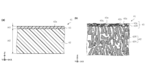
図7(a)及び図7(b)は、第2の実施形態に係る電気化学装置が含み得る第1膜を例示する模式的断面図である。図7(a)に示すように、第1膜41は、第1層42及び第2層43を含んでもよい。第1層42から第2層43への方向をZ軸方向とする。Z軸方向に対して垂直な1つの方向をX軸方向とする。Z軸方向及びX軸方向に対して垂直な方向をY軸方向とする。第1層42及び第2層43は、X-Y平面に沿って広がる。
Figures 7(a) and 7(b) are schematic cross-sectional views illustrating a first film that may be included in the electrochemical device according to the second embodiment. As shown in Figure 7(a), the
図7(b)に示すように、第1層42は、第1樹脂42Rを含む。第1樹脂42Rには、複数の孔42Hが設けられている。第1層42は、例えばポーラス層である。
As shown in FIG. 7(b), the
第1層42は第1面42aを含む。第1面42aは、第2層43に対向する面である。複数の孔42Hの少なくとも一部は、第1面42aに届く。
The
第2層43は、第1層42の第1面42aの上に設けられる。第2層43は、第2樹脂43Rを含む。第2樹脂43Rは、第1面42aに届く複数の孔42Hの少なくとも一部を塞ぐ。第2層43は、例えば、無効空隙層である。第2樹脂43Rの一部が、孔42Hの表面に近い部分の中に設けられても良い。
The
実施形態においては、ポーラスな第1層42と、第1層42の複数の孔42Hの一部を塞ぐ第2樹脂43R(第2層43)と、が設けられる。例えば、第1層42の複数の孔42Hの別の一部は、第2樹脂43Rによって塞がれない。
In this embodiment, a porous
第2樹脂43Rによって塞がれない孔42Hにより、目的とするガスが、第1膜41を通過できる。目的とするガスは、例えば、水素である。一方、複数の孔42Hの一部が第2樹脂43Rにより塞がれることで、目的としない物質は、第1膜41を通過しない。目的としない物質は、例えば、液体(水及び油など)を含む。実施形態によれば、目的とするガスが効率的に透過できる。
The
実施形態に係る電気化学装置が含み得る第1膜41によれば、例えば、高い撥水性が得られる。例えば、高い通気性が得られる。例えば、高い耐薬品性が得られる。例えば、高い耐腐食性が得られる。例えば、高い防塵性が得られる。例えば、水や油の進入が抑制される。例えば、高い信頼性が得られる。
The
実施形態において、第1樹脂42Rは、フッ素化合物を含むことが好ましい。第1樹脂42Rは、例えば、PTFE(polytetrafluoroethylene)を含む。安定した透過性が得られる。水などの透過が効果的に抑制できる。
In the embodiment, the
第2樹脂43Rは、例えば、アクリル樹脂を含む。これにより、複数の孔42Hの少なくとも一部が安定して塞がれる。例えば、目的としない物質の透過が安定して抑制できる。
The
第1層42の厚さを第1厚さt42とする。第2層43の厚さを第2厚さt43とする。これらの厚さは、Z軸方向に沿う長さである。実施形態において、例えば、第1厚さt42は、第2厚さt43よりも厚い。1つの例において、第1厚さt42は、第2厚さt43の2倍以上である。例えば、第1厚さt42は、第2厚さt43の10000倍以下でよい。例えば、目的するガスの透過性と、目的としない物質の透過の抑制と、が適切に得られる。
The thickness of the
第1層42の第1厚さt42は、例えば、10μm以上5000μm以下である。第1厚さt42は、例えば、1000μm以下でも良い。第2層43の第2厚さt43は、例えば、0.1μm以上100μm以下である。第2樹脂43Rの一部が、孔42Hの表面に近い部分の中に設けられる場合、孔42Hの表面に近い部分の中に設けられた第2樹脂43Rの厚さは、例えば0.1μm以上5μm以下で良い。
The first thickness t42 of the
第2樹脂43Rは、第1面42aの少なくとも一部を覆う。図7(b)に示すように、第1面42aは、第2樹脂43Rが設けられる第1領域42pと、第2樹脂43Rが設けられない第2領域42qと、を含む。第1領域42pの面積の、第2領域42qの面積に対する比は、0.01以上100以下である。
The
例えば、第2樹脂43Rは、開口部43oを含んで良い。第2樹脂43Rが設けられない第2領域42qが、開口部43oに対応する。開口率は、例えば1%以上99%以下で良い。
For example, the
図7(b)に示すように、この例では、第2層43は、複数の第1固体片43aをさらに含む。複数の第1固体片43aは、第2樹脂43Rにより固定される。複数の第1固体片43aは、例えば、金属、金属酸化物及び金属窒化物の少なくともいずれか1つを含む。例えば、複数の第1固体片43aは、Fe、Cr及びNiを含む。複数の第1固体片43aは、例えば、SUS(Steel Use Stainless)を含む。例えば、高い腐食性が得られる。複数の第1固体片43aは、例えば、酸化チタンを含んでも良い。
As shown in FIG. 7(b), in this example, the
複数の第1固体片43aの1つの平均のサイズ(長さ)は、例えば、0.1μm以上10μm以下である。
The average size (length) of each of the multiple first
第2の実施形態に係るセンサは、第1の実施形態で説明した電気化学装置と、筐体の内部に設けられた検出部と、を備えたセンサである。第2の実施形態に係るセンサは第1の実施形態で説明した電気化学装置を備えているため、性能を向上させたセンサを実現することができる。 The sensor according to the second embodiment is a sensor that includes the electrochemical device described in the first embodiment and a detection unit provided inside the housing. Because the sensor according to the second embodiment includes the electrochemical device described in the first embodiment, it is possible to realize a sensor with improved performance.
[第3の実施形態]
第3の実施形態によれば、第2の実施形態に記載のセンサと、処理装置と、を備え、センサは、通信部を含み、処理装置は、通信部から得た信号に基づく情報を処理可能であるセンサシステムが提供される。
[Third embodiment]
According to a third embodiment, a sensor system is provided comprising the sensor according to the second embodiment and a processing device, the sensor including a communication unit, and the processing device being capable of processing information based on a signal obtained from the communication unit.
図8は、第3の実施形態に係るセンサを例示する模式的断面図である。図8に示すように、実施形態に係るセンサシステム310は、第2の実施形態に係るセンサ210と、処理装置78と、を含む。処理装置78は、例えば、コンピュータなどを含んで良い。センサ210は、通信部45を含む。処理装置78は、通信部45から得た信号に基づく情報を処理可能である。通信部45から得た信号は、例えば、検出部30での検出結果に関する情報(データ)を含んで良い。
Figure 8 is a schematic cross-sectional view illustrating a sensor according to the third embodiment. As shown in Figure 8, a
処理装置78における、情報(検出結果)の処理は、例えば、情報(検出結果)の保存を含んで良い。情報(検出結果)の処理は、例えば、情報(検出結果)と基準値との比較を含んでも良い。処理装置78は、比較の結果に応じて、アラートなどを出力しても良い。情報(検出結果)の処理は、例えば、情報(検出結果)に関する任意の演算を含んで良い。演算は、例えば、最高値などの導出、または、平均値の導出などを含んで良い。
The processing of the information (detection result) in the
第3の実施形態に係るセンサシステムは、第2の実施形態に記載のセンサと、処理装置と、を備え、センサは、通信部を含み、処理装置は、通信部から得た信号に基づく情報を処理可能であるセンサシステムである。 The sensor system according to the third embodiment is a sensor system that includes the sensor described in the second embodiment and a processing device, where the sensor includes a communication unit and the processing device is capable of processing information based on a signal obtained from the communication unit.
(実施例)
以下、発明者が実施した実験の結果の例について説明する。多孔質構造体を筐体の内部に有する電気化学装置を90%RH(RH:Relative Humidity)の湿度雰囲気下に置いた場合に筐体内部の湿度センサが検出する湿度の増加速度を表1に示す。第1膜はポーラスPTFE膜を用いた。電気化学装置が多孔質構造体を備えていない場合の湿度の増加速度を1として、実施例の数値を記載した。
(Example)
Below, examples of the results of experiments carried out by the inventors are described. Table 1 shows the rate of increase in humidity detected by a humidity sensor inside a housing when an electrochemical device having a porous structure inside the housing is placed in an atmosphere of 90% RH (RH: Relative Humidity). A porous PTFE film was used as the first film. The rate of increase in humidity when the electrochemical device does not have a porous structure is set to 1, and the values of the examples are listed.
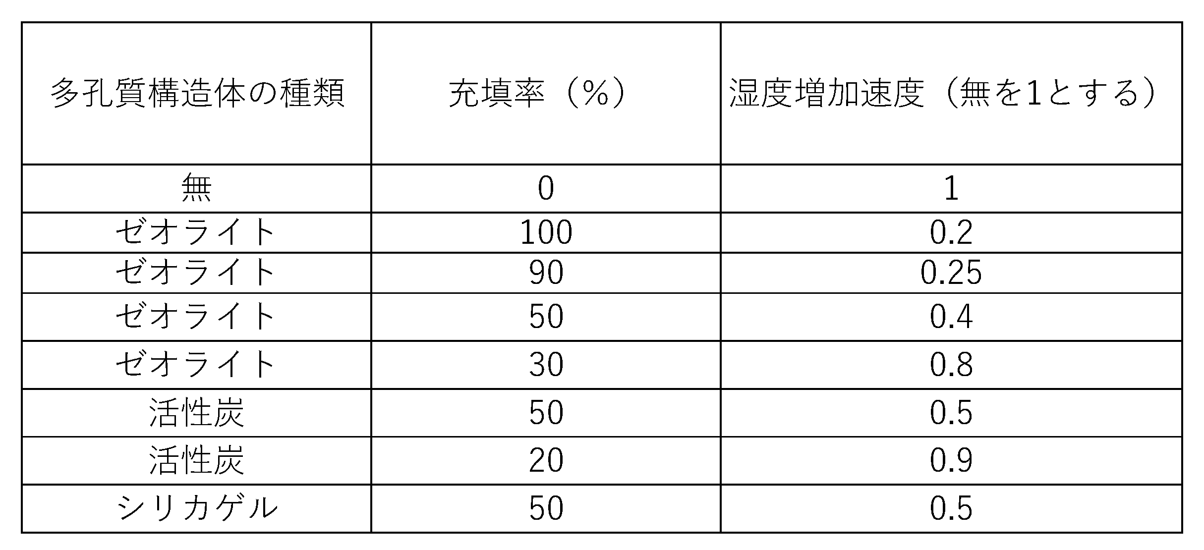
表1から、筐体の内部に多孔質構造体が無い場合と比べて、筐体の内部の少なくとも一部を多孔質構造体が占めることで、湿度センサが検出する湿度増加速度を遅くすることができるとわかる。従って、係る電気化学装置は、筐体の内部の少なくとも一部を占める多孔質構造体を有することで、センサやセンサ回路が水蒸気に長時間曝露されることを抑制し、センサのセンシング機能の低下やセンサが有するセンサ回路の故障を抑制することができる。 From Table 1, it can be seen that by having the porous structure occupy at least a portion of the interior of the housing, the rate of humidity increase detected by the humidity sensor can be slowed down compared to when there is no porous structure inside the housing. Therefore, by having a porous structure occupying at least a portion of the interior of the housing, the electrochemical device can prevent the sensor and sensor circuit from being exposed to water vapor for long periods of time, and can prevent a decrease in the sensing function of the sensor and a failure of the sensor circuit of the sensor.
本発明のいくつかの実施形態を説明したが、これらの実施形態は、例として提示したものであり、発明の範囲を限定することは意図していない。これら新規な実施形態は、その他の様々な形態で実施されることが可能であり、発明の要旨を逸脱しない範囲で、種々の省略、置き換え、変更を行うことができる。これら実施形態やその変形は、発明の範囲や要旨に含まれるとともに、特許請求の範囲に記載された発明とその均等の範囲に含まれる。 Although several embodiments of the present invention have been described, these embodiments are presented as examples and are not intended to limit the scope of the invention. These novel embodiments can be embodied in various other forms, and various omissions, substitutions, and modifications can be made without departing from the gist of the invention. These embodiments and their modifications are included in the scope and gist of the invention, and are included in the scope of the invention and its equivalents described in the claims.
以下に、実施形態に係る発明を付記する。 The following describes the invention according to the embodiment.
[1]
筐体と、
前記筐体の内部に存在する第1の電気化学素子と、
前記筐体の内部の少なくとも一部を占める多孔質構造体と、を有する電気化学装置。
[1]
A housing and
a first electrochemical device present inside the housing;
and a porous structure occupying at least a portion of the interior of the housing.
[2]
前記多孔質構造体は前記筐体の内壁の少なくとも一部を覆う、[1]に記載の電気化学装置。
[2]
The electrochemical device according to [1], wherein the porous structure covers at least a portion of an inner wall of the housing.
[3]
基板と、
第1の電池と、をさらに有し、
前記第1の電気化学素子は前記基板上に設けられ、
前記第1の電池は前記第1の電気化学素子が設けられる面と反対側の前記基板上の面に設けられる、[1]又は[2]に記載の電気化学装置。
[3]
A substrate;
a first battery,
the first electrochemical device is provided on the substrate;
The electrochemical device according to [1] or [2], wherein the first battery is provided on a surface of the substrate opposite to a surface on which the first electrochemical element is provided.
[4]
前記基板と前記第1の電池との間に前記多孔質構造体が存在する、[3]に記載の電気化学装置。
[4]
The electrochemical device according to [3], wherein the porous structure is present between the substrate and the first battery.
[5]
前記筐体は第2の電気化学素子を有する、[1]から[4]のいずれか1項に記載の電気化学装置。
[5]
The electrochemical device according to any one of [1] to [4], wherein the housing has a second electrochemical element.
[6]
前記筐体の内部に設けられる前記多孔質構造体は前記第2の電気化学素子の少なくとも一部を覆う、[5]に記載の電気化学装置。
[6]
The electrochemical device according to [5], wherein the porous structure provided inside the housing covers at least a portion of the second electrochemical element.
[7]
前記多孔質構造体はゼオライト、シリカゲル、活性アルミナ、活性炭、多孔質ポリマーからなる群より選ばれる少なくとも1つである、[1]から[6]のいずれか1項に記載の電気化学装置。
[7]
The electrochemical device according to any one of [1] to [6], wherein the porous structure is at least one selected from the group consisting of zeolite, silica gel, activated alumina, activated carbon, and porous polymers.
[8]
前記筐体の内部に設けられる前記第1の電気化学素子を除いた、前記多孔質構造体の前記筐体の内部での充填率は10%以上100%以下である、[1]から[7]のいずれか1項に記載の電気化学装置。
[8]
The electrochemical device according to any one of [1] to [7], wherein a filling rate of the porous structure inside the housing, excluding the first electrochemical element provided inside the housing, is 10% or more and 100% or less.
[9]
[1]から[8]のいずれか1項に記載の電気化学装置と、
前記筐体の内部に設けられた検出部と、を備えたセンサ。
[9]
[1] to [8], and an electrochemical device according to any one of the above.
A sensor comprising: a detection unit provided inside the housing.
[10]
[9]に記載のセンサと、
処理装置と、を備え、
前記センサは、通信部を含み、
前記処理装置は、前記通信部から得た信号に基づく情報を処理可能であるセンサシステム。
[10]
[9] A sensor according to the present invention;
A processing device,
The sensor includes a communication unit,
The processing device is a sensor system capable of processing information based on a signal obtained from the communication unit.
10…第2の電気化学素子、 11、12…第1、第2電極、 15…部材、 30…検出部、 30s…基板、 31…第1の電池、 41…第1膜、 42…第1層、 43…第2層、 45…通信部、 46…第1の電気化学素子、 50…マイコン回路、 51…電源回路、 52…電源供給部、 53…AD変換回路、 54…昇圧回路、 55…降圧回路、 70…制御部、 71…第2の電池、 75…回路部、 78…処理装置、 81…筐体、 81o…第1開口部、 81t…第1貫通孔、 85…空間、 110…電気化学装置、 210…センサ、 310…センサシステム 10...second electrochemical element, 11, 12...first and second electrodes, 15...member, 30...detection unit, 30s...substrate, 31...first battery, 41...first film, 42...first layer, 43...second layer, 45...communication unit, 46...first electrochemical element, 50...microcomputer circuit, 51...power supply circuit, 52...power supply unit, 53...AD conversion circuit, 54...boosting circuit, 55...step-down circuit, 70...control unit, 71...second battery, 75...circuit unit, 78...processing device, 81...housing, 81o...first opening, 81t...first through hole, 85...space, 110...electrochemical device, 210...sensor, 310...sensor system
Claims (10)
前記筐体の内部に存在する第1の電気化学素子と、
前記筐体の内部の少なくとも一部を占める多孔質構造体と、を有する電気化学装置。 A housing and
a first electrochemical device present inside the housing;
and a porous structure occupying at least a portion of the interior of the housing.
第1の電池と、をさらに有し、
前記第1の電気化学素子は前記基板上に設けられ、
前記第1の電池は前記第1の電気化学素子が設けられる面と反対側の前記基板上の面に設けられる、請求項1に記載の電気化学装置。 A substrate;
a first battery,
the first electrochemical device is provided on the substrate;
2. The electrochemical device according to claim 1, wherein the first battery is provided on a surface of the substrate opposite to a surface on which the first electrochemical element is provided.
前記筐体の内部に設けられた検出部と、を備えたセンサ。 The electrochemical device according to claim 1 ;
A sensor comprising: a detection unit provided inside the housing.
処理装置と、を備え、
前記センサは、通信部を含み、
前記処理装置は、前記通信部から得た信号に基づく情報を処理可能であるセンサシステム。 A sensor according to claim 9;
A processing device,
The sensor includes a communication unit,
The processing device is a sensor system capable of processing information based on a signal obtained from the communication unit.
Priority Applications (2)
| Application Number | Priority Date | Filing Date | Title |
|---|---|---|---|
| JP2023148425A JP2025041246A (en) | 2023-09-13 | 2023-09-13 | Electrochemical device, sensor and sensor system |
| US18/782,083 US20250087819A1 (en) | 2023-09-13 | 2024-07-24 | Electrochemical device, sensor, and sensor system |
Applications Claiming Priority (1)
| Application Number | Priority Date | Filing Date | Title |
|---|---|---|---|
| JP2023148425A JP2025041246A (en) | 2023-09-13 | 2023-09-13 | Electrochemical device, sensor and sensor system |
Publications (1)
| Publication Number | Publication Date |
|---|---|
| JP2025041246A true JP2025041246A (en) | 2025-03-26 |
Family
ID=94872020
Family Applications (1)
| Application Number | Title | Priority Date | Filing Date |
|---|---|---|---|
| JP2023148425A Pending JP2025041246A (en) | 2023-09-13 | 2023-09-13 | Electrochemical device, sensor and sensor system |
Country Status (2)
| Country | Link |
|---|---|
| US (1) | US20250087819A1 (en) |
| JP (1) | JP2025041246A (en) |
Citations (9)
| Publication number | Priority date | Publication date | Assignee | Title |
|---|---|---|---|---|
| JP2000074872A (en) * | 1998-08-27 | 2000-03-14 | Japan Storage Battery Co Ltd | Constant potential electrolytic gas sensor |
| JP2010144991A (en) * | 2008-12-18 | 2010-07-01 | Panasonic Corp | Refrigerator |
| JP2011145145A (en) * | 2010-01-14 | 2011-07-28 | Ngk Spark Plug Co Ltd | Gas sensor |
| JP2013257145A (en) * | 2011-05-26 | 2013-12-26 | Mitsubishi Electric Corp | Refrigerator |
| JP2016522166A (en) * | 2013-04-08 | 2016-07-28 | コミッサリア タ レネルジー アトミク エ オ エネルジー オルタネイティヴ | Method of producing combustible gas from water electrolysis (HTE) or co-electrolysis with H2O / CO2 in the same chamber and associated catalytic reactor and system |
| JP2016160527A (en) * | 2015-03-05 | 2016-09-05 | 株式会社東芝 | Low oxygen cell, storage cabinet and refrigerator |
| WO2017150216A1 (en) * | 2016-02-29 | 2017-09-08 | 京セラ株式会社 | Refrigerator and management system |
| US20170351221A1 (en) * | 2016-06-01 | 2017-12-07 | Withings | Wearable device with air quality sensor |
| JP2021117134A (en) * | 2020-01-28 | 2021-08-10 | 日本特殊陶業株式会社 | Element unit and gas sensor |
-
2023
- 2023-09-13 JP JP2023148425A patent/JP2025041246A/en active Pending
-
2024
- 2024-07-24 US US18/782,083 patent/US20250087819A1/en active Pending
Patent Citations (9)
| Publication number | Priority date | Publication date | Assignee | Title |
|---|---|---|---|---|
| JP2000074872A (en) * | 1998-08-27 | 2000-03-14 | Japan Storage Battery Co Ltd | Constant potential electrolytic gas sensor |
| JP2010144991A (en) * | 2008-12-18 | 2010-07-01 | Panasonic Corp | Refrigerator |
| JP2011145145A (en) * | 2010-01-14 | 2011-07-28 | Ngk Spark Plug Co Ltd | Gas sensor |
| JP2013257145A (en) * | 2011-05-26 | 2013-12-26 | Mitsubishi Electric Corp | Refrigerator |
| JP2016522166A (en) * | 2013-04-08 | 2016-07-28 | コミッサリア タ レネルジー アトミク エ オ エネルジー オルタネイティヴ | Method of producing combustible gas from water electrolysis (HTE) or co-electrolysis with H2O / CO2 in the same chamber and associated catalytic reactor and system |
| JP2016160527A (en) * | 2015-03-05 | 2016-09-05 | 株式会社東芝 | Low oxygen cell, storage cabinet and refrigerator |
| WO2017150216A1 (en) * | 2016-02-29 | 2017-09-08 | 京セラ株式会社 | Refrigerator and management system |
| US20170351221A1 (en) * | 2016-06-01 | 2017-12-07 | Withings | Wearable device with air quality sensor |
| JP2021117134A (en) * | 2020-01-28 | 2021-08-10 | 日本特殊陶業株式会社 | Element unit and gas sensor |
Also Published As
| Publication number | Publication date |
|---|---|
| US20250087819A1 (en) | 2025-03-13 |
Similar Documents
| Publication | Publication Date | Title |
|---|---|---|
| TWI283942B (en) | Electrochemical cells, and gas sensor and fuel cell devices comprising same | |
| US10816502B2 (en) | Using a biased electrochemical sensor for acrylonitrile detection | |
| US10386325B2 (en) | Gas sensor with partitioned filter | |
| JP3219610B2 (en) | Electrochemical element | |
| US10816503B2 (en) | Electrochemical gas sensor for detecting hydrogen cyanide gas | |
| JP2014161760A (en) | Dehumidifier for apparatus and on-vehicle head lamp | |
| JP2011253789A5 (en) | ||
| WO2025246216A1 (en) | Safe device for active electrolysis of water molecules, and apparatus | |
| WO2020137467A1 (en) | Humidity control element and humidity control unit | |
| CN1755353A (en) | Gas sensor | |
| JP2025041246A (en) | Electrochemical device, sensor and sensor system | |
| JP7623972B2 (en) | Electrochemical device, sensor and sensor system | |
| JP4377184B2 (en) | Electrochemical air purification device | |
| JP2024128451A (en) | Electrochemical device, sensor and sensor system | |
| US20240082764A1 (en) | Filter, gas sensor, and gas sensor system | |
| EP1416560A1 (en) | Operating method of fuel cell and power supply | |
| JP4562131B2 (en) | Separator for working electrode of electrochemical gas sensor for detecting nitrogen dioxide (NO2), nitric oxide (NO), sulfur dioxide (SO2) | |
| JP4516195B2 (en) | Constant potential electrolytic gas sensor | |
| JP6474285B2 (en) | Constant potential electrolytic gas sensor | |
| JP6752558B2 (en) | Constant potential electrolytic gas sensor | |
| JP6576053B2 (en) | Constant potential electrolytic gas sensor | |
| JP2005324152A (en) | Air treatment apparatus | |
| CN222550564U (en) | Safe active electrolysis water molecule device with one-way accelerated exhaust | |
| JP2013519072A (en) | Stand-alone water detector with hydrogen source | |
| JPH02227118A (en) | Malodor removal device and method |
Legal Events
| Date | Code | Title | Description |
|---|---|---|---|
| RD07 | Notification of extinguishment of power of attorney |
Free format text: JAPANESE INTERMEDIATE CODE: A7427 Effective date: 20240719 |
|
| RD07 | Notification of extinguishment of power of attorney |
Free format text: JAPANESE INTERMEDIATE CODE: A7427 Effective date: 20250110 |
|
| A621 | Written request for application examination |
Free format text: JAPANESE INTERMEDIATE CODE: A621 Effective date: 20250307 |
|
| RD07 | Notification of extinguishment of power of attorney |
Free format text: JAPANESE INTERMEDIATE CODE: A7427 Effective date: 20250321 |
|
| A977 | Report on retrieval |
Free format text: JAPANESE INTERMEDIATE CODE: A971007 Effective date: 20251226 |
|
| A131 | Notification of reasons for refusal |
Free format text: JAPANESE INTERMEDIATE CODE: A131 Effective date: 20260109 |
|
| A601 | Written request for extension of time |
Free format text: JAPANESE INTERMEDIATE CODE: A601 Effective date: 20260310 |
|
| RD02 | Notification of acceptance of power of attorney |
Free format text: JAPANESE INTERMEDIATE CODE: A7422 Effective date: 20260310 |
|
| RD07 | Notification of extinguishment of power of attorney |
Free format text: JAPANESE INTERMEDIATE CODE: A7427 Effective date: 20260326 |
|
| A521 | Request for written amendment filed |
Free format text: JAPANESE INTERMEDIATE CODE: A821 Effective date: 20260326 |