JP2025041245A - A method for producing a precursor and a positive electrode active material for a lithium secondary battery. - Google Patents
A method for producing a precursor and a positive electrode active material for a lithium secondary battery. Download PDFInfo
- Publication number
- JP2025041245A JP2025041245A JP2023148424A JP2023148424A JP2025041245A JP 2025041245 A JP2025041245 A JP 2025041245A JP 2023148424 A JP2023148424 A JP 2023148424A JP 2023148424 A JP2023148424 A JP 2023148424A JP 2025041245 A JP2025041245 A JP 2025041245A
- Authority
- JP
- Japan
- Prior art keywords
- precursor
- lithium secondary
- secondary battery
- positive electrode
- particle size
- Prior art date
- Legal status (The legal status is an assumption and is not a legal conclusion. Google has not performed a legal analysis and makes no representation as to the accuracy of the status listed.)
- Pending
Links
Images

Classifications
-
- Y—GENERAL TAGGING OF NEW TECHNOLOGICAL DEVELOPMENTS; GENERAL TAGGING OF CROSS-SECTIONAL TECHNOLOGIES SPANNING OVER SEVERAL SECTIONS OF THE IPC; TECHNICAL SUBJECTS COVERED BY FORMER USPC CROSS-REFERENCE ART COLLECTIONS [XRACs] AND DIGESTS
- Y02—TECHNOLOGIES OR APPLICATIONS FOR MITIGATION OR ADAPTATION AGAINST CLIMATE CHANGE
- Y02E—REDUCTION OF GREENHOUSE GAS [GHG] EMISSIONS, RELATED TO ENERGY GENERATION, TRANSMISSION OR DISTRIBUTION
- Y02E60/00—Enabling technologies; Technologies with a potential or indirect contribution to GHG emissions mitigation
- Y02E60/10—Energy storage using batteries
Landscapes
- Inorganic Compounds Of Heavy Metals (AREA)
- Battery Electrode And Active Subsutance (AREA)
Abstract
Description
本発明は、前駆体、リチウム二次電池用正極活物質の製造方法に関する。 The present invention relates to a precursor and a method for producing a positive electrode active material for lithium secondary batteries.
リチウム二次電池の正極は、リチウム二次電池用正極活物質を有する。リチウム二次電池用正極活物質は、例えば、リチウム化合物と前駆体との混合物を焼成することで得られる。前駆体は、例えばLi以外の金属元素を含む金属複合酸化物である。 The positive electrode of the lithium secondary battery has a positive electrode active material for lithium secondary batteries. The positive electrode active material for lithium secondary batteries is obtained, for example, by firing a mixture of a lithium compound and a precursor. The precursor is, for example, a metal composite oxide containing a metal element other than Li.
リチウム二次電池の電池性能を向上させる技術として、前駆体の結晶の状態を制御する試みがなされている。 Attempts are being made to control the crystal state of precursors as a technique for improving the battery performance of lithium secondary batteries.
例えば特許文献1は、共沈殿工程で得られたニッケルコバルトマンガン複合水酸化物を、酸化焙焼して、ニッケルコバルトマンガン複合酸化物を得る工程を備える、正極活物質の製造方法を開示している。
特許文献1は、このような前駆体を原料とする正極活物質を用いると、リチウム二次電池の初期放電容量と容量維持率が向上することを開示している。
For example,
リチウム二次電池の応用分野の拡大が進む中、放電レート特性及び初回充放電効率が向上するリチウム二次電池を製造可能な前駆体が求められる。 As the range of applications for lithium secondary batteries continues to expand, there is a demand for precursors that can be used to manufacture lithium secondary batteries with improved discharge rate characteristics and initial charge/discharge efficiency.
本発明はこのような事情に鑑みてなされたものであって、放電レート特性に優れ、初回充放電効率が高いリチウム二次電池を製造可能なリチウム二次電池用正極活物質の前駆体を提供することを目的とする。さらにこのような前駆体を用いたリチウム二次電池用正極活物質の製造方法を提供することを目的とする。 The present invention has been made in consideration of the above circumstances, and aims to provide a precursor for a positive electrode active material for a lithium secondary battery that can be used to manufacture a lithium secondary battery that has excellent discharge rate characteristics and high initial charge/discharge efficiency. It also aims to provide a method for manufacturing a positive electrode active material for a lithium secondary battery using such a precursor.
本発明の一態様は[1]~[9]を包含する。
[1]リチウム二次電池用正極活物質の前駆体であって、少なくともNiと、Co及び元素M1からなる群より選択される1種以上の元素とを含有し、下記(1)及び(2)を満たす、前駆体。
(1)窒素吸着等温線からBarrett-Joyner-Halenda(BJH)法により算出した細孔径分布において、細孔径が2nm以上200nm以下の範囲における全細孔容積が、0.115cm3/g以上0.180cm3/g以下である。
(2)0.84<A/B<0.95
(Aは、CuKα線源を使用した粉末X線回折測定において、2θ=37.5±1°の範囲内に存在する回折ピークの半値幅であり、Bは、2θ=43.5±1°の範囲内に存在する回折ピークの半値幅である。)
[2]下記(3)を満たす、[1]に記載の前駆体。
(3)0.6×10⁻³≦C/D50≦1.6×10-3
(Cは、前記細孔径分布における平均細孔径(nm)であり、D50は、レーザー回折散乱法により測定される体積基準の累積粒度分布曲線から得られる50%累積体積粒度(μm)である。)
[3]下記(4)を満たす、[1]又は[2]に記載の前駆体。
(4)1.0×10⁻³≦C/D10≦2.5×10-3
(Cは、前記細孔径分布における平均細孔径(nm)であり、D10は、レーザー回折散乱法により測定される体積基準の累積粒度分布曲線から得られる10%累積体積粒度(μm)である。)
[4]下記(5)を満たす、[1]~[3]のいずれか1つに記載の前駆体。
(5)0.4×10⁻³≦C/D90≦1.0×10-3
(Cは、前記細孔径分布における平均細孔径(nm)であり、D90は、レーザー回折散乱法により測定される体積基準の累積粒度分布曲線から得られる90%累積体積粒度(μm)である。)
[5]BET比表面積が25m2/g以上100m2/g以下である、[1]~[4]のいずれか1つに記載の前駆体。
[6]前記細孔径分布における平均細孔径であるCが8nm以上20nm以下である、[1]~[5]のいずれか1つに記載の前駆体。
[7]レーザー回折散乱法により測定される体積基準の累積粒度分布曲線から得られる50%累積体積粒度であるD50が、10μm以上20μm以下である、[1]~[6]のいずれか1つに記載の前駆体。
[8]下記式(I)を満たす、[1]~[7]のいずれか1つに記載の前駆体。
Ni:Co:M1=(1-y-z):y:z ・・・(I)
(M1は、Mn、Mg、Ca、Sr、Ba、Zn、B、Al、Ga、Ti、Zr、Ge、Fe、Cu、Cr、V、W、Mo、Sc、Y、Nb、La、Ta、Tc、Ru、Rh、Pd、Ag、Cd、In及びSnからなる群より選択される1種以上の元素である。式(I)は、0≦y≦0.4、0≦z≦0.5、及び0<y+zを満たす。)
[9][1]~[8]のいずれか1つに記載の前駆体とリチウム化合物との混合物を焼成する工程を備える、リチウム二次電池用正極活物質の製造方法。
An embodiment of the present invention includes [1] to [9].
[1] A precursor of a positive electrode active material for a lithium secondary battery, the precursor containing at least Ni and one or more elements selected from the group consisting of Co and element M1, and satisfying the following (1) and (2):
(1) In the pore size distribution calculated from the nitrogen adsorption isotherm by the Barrett-Joyner-Halenda (BJH) method, the total pore volume in the pore size range of 2 nm or more and 200 nm or less is 0.115 cm 3 /g or more and 0.180 cm 3 /g or less.
(2) 0.84<A/B<0.95
(A is the half-width of a diffraction peak present within the range of 2θ=37.5±1° in powder X-ray diffraction measurement using a CuKα radiation source, and B is the half-width of a diffraction peak present within the range of 2θ=43.5±1°.)
[2] The precursor according to [1], which satisfies the following (3):
(3) 0.6×10 -3 ≦C/D 50 ≦1.6×10 -3
(C is the average pore diameter (nm) in the pore diameter distribution, and D50 is the 50% cumulative volume particle size (μm) obtained from a volume-based cumulative particle size distribution curve measured by a laser diffraction scattering method.)
[3] The precursor according to [1] or [2], which satisfies the following (4):
(4) 1.0×10 -3 ≦C/D 10 ≦2.5×10 -3
(C is the average pore diameter (nm) in the pore diameter distribution, and D10 is the 10% cumulative volume particle size (μm) obtained from a volume-based cumulative particle size distribution curve measured by a laser diffraction scattering method.)
[4] The precursor according to any one of [1] to [3], which satisfies the following (5):
(5) 0.4×10 -3 ≦C/D 90 ≦1.0×10 -3
(C is the average pore diameter (nm) in the pore diameter distribution, and D 90 is the 90% cumulative volume particle size (μm) obtained from a volume-based cumulative particle size distribution curve measured by a laser diffraction scattering method.)
[5] The precursor according to any one of [1] to [4], which has a BET specific surface area of 25 m 2 /g or more and 100 m 2 /g or less.
[6] The precursor according to any one of [1] to [5], wherein C, which is an average pore diameter in the pore diameter distribution, is 8 nm or more and 20 nm or less.
[7] The precursor according to any one of [1] to [6], wherein D50 , which is the 50% cumulative volume particle size obtained from a volume-based cumulative particle size distribution curve measured by a laser diffraction scattering method, is 10 μm or more and 20 μm or less.
[8] The precursor according to any one of [1] to [7], which satisfies the following formula (I):
Ni:Co:M1=(1-y-z):y:z...(I)
(M1 is one or more elements selected from the group consisting of Mn, Mg, Ca, Sr, Ba, Zn, B, Al, Ga, Ti, Zr, Ge, Fe, Cu, Cr, V, W, Mo, Sc, Y, Nb, La, Ta, Tc, Ru, Rh, Pd, Ag, Cd, In, and Sn. Formula (I) satisfies 0≦y≦0.4, 0≦z≦0.5, and 0<y+z.)
[9] A method for producing a positive electrode active material for a lithium secondary battery, comprising a step of calcining a mixture of the precursor according to any one of [1] to [8] and a lithium compound.
本発明によれば、放電レート特性に優れ、初回充放電効率が高いリチウム二次電池を製造可能なリチウム二次電池用正極活物質の前駆体を提供することができる。さらにこのような前駆体を用いたリチウム二次電池用正極活物質の製造方法を提供することができる。 According to the present invention, it is possible to provide a precursor of a positive electrode active material for a lithium secondary battery that can be used to manufacture a lithium secondary battery having excellent discharge rate characteristics and high initial charge/discharge efficiency. Furthermore, it is possible to provide a method for manufacturing a positive electrode active material for a lithium secondary battery using such a precursor.
<用語の定義>
本明細書で用いる用語について、以下のように定義する。
用語「CAM」は、リチウム二次電池用正極活物質(Cathode Active Material for lithium secondary batteries)を意味する。リチウム二次電池は、リチウムイオン二次電池を示す。
<Definition of terms>
The terms used in this specification are defined as follows.
The term "CAM" means a cathode active material for lithium secondary batteries. A lithium secondary battery refers to a lithium ion secondary battery.
金属の元素記号を示す表現(例えば「Ni」)は、特に言及しない限り金属単体ではなく元素を示す。なお、本明細書において「金属元素」には、半金属元素であるBも含まれる。 Unless otherwise specified, an expression indicating the atomic symbol of a metal (e.g., "Ni") indicates the element, not the metal itself. In this specification, "metal element" also includes B, which is a metalloid element.
数値範囲について、例えば「1~10μm」と記載した場合、1μmから10μmまでの範囲であって下限値(1μm)と上限値(10μm)を含む数値範囲、すなわち「1μm以上10μm以下」を意味する。 When referring to a numerical range, for example, "1 to 10 μm" is stated, this means a numerical range from 1 μm to 10 μm including the lower limit (1 μm) and the upper limit (10 μm), i.e., "1 μm or more and 10 μm or less."
[全細孔容積の測定方法]
前駆体の「細孔径分布」は、前駆体を液体窒素温度で測定して得られる窒素脱離等温線を、Barrett-Joyner-Halenda(BJH)法で解析して求められる。窒素脱離等温線の測定装置としては、例えばBELSORP-mini(マイクロトラック・ベル株式会社製)を使用できる。
[Method for measuring total pore volume]
The "pore size distribution" of the precursor is determined by analyzing the nitrogen desorption isotherm obtained by measuring the precursor at liquid nitrogen temperature using the Barrett-Joyner-Halenda (BJH) method. As a measuring device for the nitrogen desorption isotherm, for example, BELSORP-mini (manufactured by Microtrack BEL Co., Ltd.) can be used.
まず、真空加熱処理装置(BELSORP-vacII、マイクロトラック・ベル株式会社製)を用いて、前駆体5gを105℃で8時間真空脱気処理する。処理後、上記測定装置を用いて、前駆体の液体窒素温度(77K)における窒素の吸着量を測定し、窒素脱離等温線を作成する。 First, 5 g of the precursor is vacuum degassed at 105°C for 8 hours using a vacuum heat treatment device (BELSORP-vacII, manufactured by Microtrack-Bell Co., Ltd.). After the treatment, the amount of nitrogen adsorbed by the precursor at liquid nitrogen temperature (77K) is measured using the above-mentioned measuring device, and a nitrogen desorption isotherm is created.
窒素脱離等温線は、横軸を吸着平衡圧と飽和蒸気圧との比(相対圧(ρ/ρ0))、縦軸を標準状態(STP;Standard Temperature and Pressure)における気体窒素の吸着量(cm3(STP)/g)としてプロットしたものである。 The nitrogen desorption isotherm is plotted with the horizontal axis representing the ratio of the adsorption equilibrium pressure to the saturated vapor pressure (relative pressure (ρ/ρ0)) and the vertical axis representing the amount of gaseous nitrogen adsorbed (cm 3 (STP)/g) at standard temperature and pressure (STP).
得られた窒素脱離等温線を、BJH法により解析して細孔径が2~200nmの領域における細孔径分布を求める。細孔径分布は、差分細孔容積dVを、細孔径Dの対数扱いの差分値d(logD)で割った値を求め、横軸を細孔径(nm、対数目盛)、縦軸をlog微分細孔容積(cm3/g)としてプロットしたものである。 The obtained nitrogen desorption isotherm is analyzed by the BJH method to determine the pore size distribution in the pore size range of 2 to 200 nm. The pore size distribution is calculated by dividing the differential pore volume dV by the logarithmic differential value d (logD) of the pore diameter D, and plotting the value with the pore diameter (nm, logarithmic scale) on the horizontal axis and the log differential pore volume ( cm3 /g) on the vertical axis.
上記の方法で得られた細孔径分布において、細孔径が2~200nmの範囲における、前駆体の全細孔容積を求める。 In the pore size distribution obtained by the above method, the total pore volume of the precursor in the pore size range of 2 to 200 nm is calculated.
[粉末X線回折測定]
前駆体の粉末X線回折測定は、粉末X線回折測定装置を用いて行う。粉末X線回折測定装置は、例えば、株式会社リガク製UltimaIVが使用できる。
具体的には、前駆体の粉末を専用の基板に充填し、Cu-Kα線源を用いて、回折角2θ=10-90°、サンプリング幅0.02°、スキャンスピード4°/minの条件にて測定を行うことで、粉末X線回折図形を得る。得られた粉末X線回折図形から、2θ=37.5±1°の範囲内に存在する回折ピークの半値幅Aと、2θ=43.5±1°の範囲内に存在する回折ピークの半値幅Bとを解析ソフトウェア(例えば、統合粉末X線解析ソフトウェアJADE)により解析し、その比(A/B)を算出する。
[Powder X-ray diffraction measurement]
The powder X-ray diffraction measurement of the precursor is carried out using a powder X-ray diffraction measurement device, such as Ultima IV manufactured by Rigaku Corporation.
Specifically, the precursor powder is filled into a dedicated substrate, and a Cu-Kα source is used to perform measurements under the conditions of a diffraction angle 2θ=10-90°, a sampling width of 0.02°, and a scan speed of 4°/min to obtain a powder X-ray diffraction pattern. From the obtained powder X-ray diffraction pattern, the half-width A of the diffraction peak present in the range of 2θ=37.5±1° and the half-width B of the diffraction peak present in the range of 2θ=43.5±1° are analyzed using analysis software (e.g., integrated powder X-ray analysis software JADE), and the ratio (A/B) is calculated.
[平均細孔径の測定方法]
上記[全細孔容積の測定方法]にて得られる細孔径分布から、細孔径が2~200nmの領域における前駆体の平均細孔径Cを求める。
[Method of measuring average pore diameter]
From the pore size distribution obtained by the above [Method of Measuring Total Pore Volume], the average pore size C of the precursor in the pore size range of 2 to 200 nm is determined.
[粒度分布の測定方法]
前駆体の粒度分布は、体積基準で求められ、レーザー回折散乱法を測定原理とする装置を用いて測定する。具体的には、前駆体の粉末0.1gを、0.2質量%ヘキサメタりん酸ナトリウム水溶液50mlに投入し、前記粉末を分散させた分散液を得る。次に、得られた分散液について粒度分布測定装置を用いて、粒度分布を測定し、体積基準の累積粒度分布曲線を得る。粒度分布測定装置は、例えばMT3000II(マイクロトラック・ベル社製)を使用できる。
[Method of measuring particle size distribution]
The particle size distribution of the precursor is determined on a volume basis and is measured using a device that uses a laser diffraction scattering method as the measurement principle. Specifically, 0.1 g of the precursor powder is put into 50 ml of a 0.2 mass% aqueous solution of sodium hexametaphosphate to obtain a dispersion in which the powder is dispersed. Next, the particle size distribution of the obtained dispersion is measured using a particle size distribution measuring device to obtain a cumulative particle size distribution curve on a volume basis. For example, the particle size distribution measuring device may be an MT3000II (manufactured by Microtrack Bell).
得られた体積基準の累積粒度分布曲線において、全体を100%としたときに、小粒子側からの累積体積割合が50%となる粒子径を50%累積体積粒度(D50(μm))、10%となる粒子径を10%累積体積粒度(D10(μm))、90%となる粒子径を90%累積体積粒度(D90(μm))とする。 In the obtained volume-based cumulative particle size distribution curve, when the whole is taken as 100%, the particle size at which the cumulative volume ratio from the small particle side is 50% is taken as the 50% cumulative volume particle size (D 50 (μm)), the particle size at which it is 10% is taken as the 10% cumulative volume particle size (D 10 (μm)), and the particle size at which it is 90% is taken as the 90% cumulative volume particle size (D 90 (μm)).
[BET比表面積の測定方法]
前駆体のBET比表面積(単位:m2/g)は、前駆体粉末1gを窒素雰囲気中、105℃で30分間乾燥させた後、BET比表面積測定装置により測定できる。BET比表面積測定装置としては、例えばマウンテック社製Macsorb(登録商標)が使用できる。
[Method for measuring BET specific surface area]
The BET specific surface area (unit: m2 /g) of the precursor can be measured by a BET specific surface area measuring device after drying 1 g of the precursor powder in a nitrogen atmosphere at 105°C for 30 minutes. As the BET specific surface area measuring device, for example, Macsorb (registered trademark) manufactured by Mountech Co., Ltd. can be used.
[組成分析]
前駆体の組成は、前駆体粉末を塩酸に溶解させた後、ICP発光分光分析装置を用いて測定する。ICP発光分光分析装置としては、例えばOptima7300(株式会社パーキンエルマー製)を使用できる。
[Composition Analysis]
The composition of the precursor is measured by dissolving the precursor powder in hydrochloric acid and then using an ICP emission spectrometer such as Optima 7300 (manufactured by PerkinElmer Co., Ltd.).
[前駆体の評価方法]
前駆体の評価は、以下の方法でリチウム二次電池を作製した後に行う。
[Precursor evaluation method]
The precursor is evaluated after a lithium secondary battery is produced by the following method.
(CAMの作製)
前駆体と水酸化リチウム一水和物粉末を、モル比がLi/(Ni+Co+M1)=1.02となる割合で秤量して混合し、混合物を得る。得られた混合物を酸素含有雰囲気下、650℃で5時間焼成した後、さらに740℃で5時間焼成して焼成物を得る。焼成物と液温を5℃に調整した純水とを、全体量に対して焼成物の重量の割合が50質量%になる割合で混合してスラリーを作製する。スラリーを20分間撹拌させて洗浄した後、脱水し、窒素雰囲気において210℃で10時間熱処理してCAMを得る。
(CAM Creation)
The precursor and lithium hydroxide monohydrate powder are weighed and mixed in a molar ratio of Li/(Ni+Co+M1)=1.02 to obtain a mixture. The obtained mixture is calcined at 650°C for 5 hours in an oxygen-containing atmosphere, and then calcined at 740°C for 5 hours to obtain a calcined product. The calcined product and pure water whose liquid temperature is adjusted to 5°C are mixed in a ratio such that the weight ratio of the calcined product to the total amount is 50 mass% to prepare a slurry. The slurry is stirred for 20 minutes, washed, dehydrated, and heat-treated at 210°C for 10 hours in a nitrogen atmosphere to obtain a CAM.
(リチウム二次電池用正極の作製)
得られたCAMと、導電材(アセチレンブラック)とバインダー(PVdF)とを、CAM:導電材:バインダー=92:5:3(質量比)の組成となる割合で加えて混練し、ペースト状の正極合剤を調製する。正極合剤の調製時には、N-メチル-2-ピロリドンを有機溶媒として用いる。
(Preparation of positive electrode for lithium secondary battery)
The obtained CAM, a conductive material (acetylene black), and a binder (PVdF) are added and kneaded in a ratio of CAM:conductive material:binder=92:5:3 (mass ratio) to prepare a paste-like positive electrode mixture. When preparing the positive electrode mixture, N-methyl-2-pyrrolidone is used as an organic solvent.
得られた正極合剤を、集電体となる厚さ40μmのAl箔に塗布して150℃で8時間真空乾燥を行い、リチウム二次電池用正極を得る。このリチウム二次電池用正極の電極面積を1.65cm2とする。 The obtained positive electrode mixture is applied to an Al foil having a thickness of 40 μm as a current collector, and then vacuum dried at 150° C. for 8 hours to obtain a positive electrode for a lithium secondary battery. The electrode area of this positive electrode for a lithium secondary battery is 1.65 cm 2 .
(リチウム二次電池の作製)
以下の操作を、アルゴン雰囲気のグローブボックス内で行う。
(リチウム二時電池用正極の作製)で作製されるリチウム二次電池用正極を、コイン型電池R2032用のパーツ(例えば、宝泉株式会社製)の下蓋にアルミ箔面を下に向けて置き、その上にセパレータ(ポリエチレン製多孔質フィルム)を置く。ここに電解液を300μL注入する。電解液は、エチレンカーボネートとジメチルカーボネートとエチルメチルカーボネートを30:35:35(体積比)で混合した混合液に、LiPF6を1.0mol/Lとなる割合で溶解した液体を用いる。
(Preparation of Lithium Secondary Battery)
The following operations are carried out in a glove box under an argon atmosphere.
The positive electrode for lithium secondary battery prepared in (Preparation of positive electrode for lithium secondary battery) is placed on the bottom cover of a part for coin type battery R2032 (for example, manufactured by Hosen Co., Ltd.) with the aluminum foil side facing down, and a separator (polyethylene porous film) is placed on top of it. 300 μL of electrolyte is poured here. The electrolyte is a liquid obtained by dissolving LiPF 6 at a ratio of 1.0 mol/L in a mixture of ethylene carbonate, dimethyl carbonate, and ethyl methyl carbonate in a ratio of 30:35:35 (volume ratio).
次に、負極として金属リチウムを用いて、前記負極を上記セパレータの上側に置き、ガスケットを介して上蓋をし、かしめ機でかしめてリチウム二次電池(コイン型ハーフセルR2032)を作製する。作製したリチウム二次電池は、室温で12時間静置し、セパレータ及び正極合剤層に対し充分に電解液を含浸させた後に、後述の測定に用いられる。 Next, metallic lithium is used as the negative electrode, and the negative electrode is placed on the top of the separator, and the top lid is placed over the gasket and crimped with a crimping machine to prepare a lithium secondary battery (coin-type half cell R2032). The lithium secondary battery thus prepared is left to stand at room temperature for 12 hours to allow the separator and positive electrode mixture layer to be sufficiently impregnated with the electrolyte, and then used for the measurements described below.
上記(リチウム二次電池の作製)で作製したリチウム二次電池を用いて以下の条件で放電レート試験を実施する。 A discharge rate test is carried out under the following conditions using the lithium secondary battery prepared above (Preparation of lithium secondary battery).
(放電レート試験)
試験温度:25℃
充電最大電圧4.3V、充電電流0.2CA、定電流定電圧充電
放電最小電圧2.5V、放電電流0.2CAまたは1CA、定電流放電
(Discharge rate test)
Test temperature: 25°C
Maximum charging voltage 4.3V, charging current 0.2CA, constant current constant voltage charging Minimum discharging voltage 2.5V, discharging current 0.2CA or 1CA, constant current discharging
0.2CAで定電流放電させたときの放電容量と1CAで定電流放電させたときの放電容量とを用い、以下の式(X)で1CA/0.2CA放電容量比率を求め、放電レート特性の指標とする。
1CA/0.2CA放電容量比率(%)
=1CAにおける放電容量/0.2CAにおける放電容量×100 ・・・式(X)
The discharge capacity when discharged at a constant current of 0.2 CA and the discharge capacity when discharged at a constant current of 1 CA were used to calculate the 1 CA/0.2 CA discharge capacity ratio according to the following formula (X), which is used as an index of discharge rate characteristics.
1CA/0.2CA discharge capacity ratio (%)
= Discharge capacity at 1 CA / Discharge capacity at 0.2 CA × 100 Formula (X)
上記の方法により得られる1CA/0.2CA放電容量比率が93.0%以上であると、「放電レート特性に優れる」と評価する。 If the 1CA/0.2CA discharge capacity ratio obtained by the above method is 93.0% or more, it is evaluated as having "excellent discharge rate characteristics."
上記(リチウム二次電池の作製)で作製したリチウム二次電池を用いて、以下に示す条件で初回充放電試験を実施する。初回充放電試験で得られる初回充電容量と初回放電容量から、下記の式(Y)で初回充放電効率を算出する。
初回充放電効率(%)
=初回放電容量(mAh/g)/初回充電容量(mAh/g)×100 ・・・式(Y)
Using the lithium secondary battery prepared in the above (Preparation of lithium secondary battery), an initial charge/discharge test is carried out under the following conditions. The initial charge/discharge efficiency is calculated from the initial charge capacity and initial discharge capacity obtained in the initial charge/discharge test using the following formula (Y).
Initial charge/discharge efficiency (%)
= initial discharge capacity (mAh/g) / initial charge capacity (mAh/g) × 100 ... formula (Y)
(充放電試験条件)
試験温度:25℃
充電最大電圧4.3V、充電電流0.2CA、定電流定電圧充電
放電最小電圧2.5V、放電電流0.2CA、定電流放電
(Charge/discharge test conditions)
Test temperature: 25°C
Maximum charging voltage 4.3V, charging current 0.2CA, constant current constant voltage charging Minimum discharging voltage 2.5V, discharging current 0.2CA, constant current discharging
上記の方法により得られる初回充放電効率が87.0%以上であると、「初回充放電効率が高い」と評価する。 If the initial charge/discharge efficiency obtained by the above method is 87.0% or more, it is evaluated as having a "high initial charge/discharge efficiency."
<前駆体>
本実施形態の前駆体は、少なくともNiと、Co及び元素M1からなる群より選択される1種以上の元素とを含む。前駆体は、層状構造を有する六方晶系の化合物であることが好ましい。前駆体は、実質的にLiを含まない。
上記前駆体は、Niと、Coと元素M1とを含むことが好ましい。元素M1は、Mn、Mg、Ca、Sr、Ba、Zn、B、Al、Ga、Ti、Zr、Ge、Fe、Cu、Cr、V、W、Mo、Sc、Y、Nb、La、Ta、Tc、Ru、Rh、Pd、Ag、Cd、In及びSnからなる群より選択される1種以上の元素である。
<Precursor>
The precursor of this embodiment contains at least Ni and one or more elements selected from the group consisting of Co and element M1. The precursor is preferably a hexagonal compound having a layered structure. The precursor does not substantially contain Li.
The precursor preferably contains Ni, Co, and an element M1, the element M1 being one or more elements selected from the group consisting of Mn, Mg, Ca, Sr, Ba, Zn, B, Al, Ga, Ti, Zr, Ge, Fe, Cu, Cr, V, W, Mo, Sc, Y, Nb, La, Ta, Tc, Ru, Rh, Pd, Ag, Cd, In, and Sn.
上記前駆体は、下記(1)と(2)を満たす。
(1)窒素吸着等温線からBarrett-Joyner-Halenda(BJH)法により算出した細孔径分布において、細孔径が2~200nmの範囲における全細孔容積が、0.115~0.180cm3/g以下である。
(2)0.84<A/B<0.95
(Aは、CuKα線源を使用した粉末X線回折測定において、2θ=37.5±1°の範囲内に存在する回折ピークの半値幅であり、Bは、2θ=43.5±1°の範囲内に存在する回折ピークの半値幅である。)
以下、それぞれの要件について説明する。
The precursor satisfies the following (1) and (2).
(1) In the pore size distribution calculated from the nitrogen adsorption isotherm by the Barrett-Joyner-Halenda (BJH) method, the total pore volume in the pore size range of 2 to 200 nm is 0.115 to 0.180 cm 3 /g or less.
(2) 0.84<A/B<0.95
(A is the half-width of a diffraction peak present within the range of 2θ=37.5±1° in powder X-ray diffraction measurement using a CuKα radiation source, and B is the half-width of a diffraction peak present within the range of 2θ=43.5±1°.)
Each requirement will be explained below.
(1)
前駆体の全細孔容積は、0.118cm3/g以上が好ましく、0.120cm3/g以上がより好ましい。前駆体の全細孔容積は、0.170cm3/g以下が好ましく、0.160cm3/g以下がより好ましく、0.157cm3/g以下がさらに好ましい。前駆体の全細孔容積は、0.118~0.170cm3/gが好ましく、0.120~0.160cm3/gがより好ましく、0.120~0.157cm3/gがさらに好ましい。
(1)
The total pore volume of the precursor is preferably 0.118 cm 3 /g or more, more preferably 0.120 cm 3 /g or more. The total pore volume of the precursor is preferably 0.170 cm 3 /g or less, more preferably 0.160 cm 3 /g or less, and even more preferably 0.157 cm 3 /g or less. The total pore volume of the precursor is preferably 0.118 to 0.170 cm 3 /g, more preferably 0.120 to 0.160 cm 3 /g, and even more preferably 0.120 to 0.157 cm 3 /g.
全細孔容積が上記下限値以上である前駆体は、反応サイトとなりうる十分な細孔を有する。このような前駆体を原料として用いて作製されたCAMは、充電時にリチウムイオンが挿入し、放電時にリチウムイオンが脱離できる反応サイトが十分に存在しやすく、充電時及び放電時にリチウムイオンが拡散しやすい、すなわち内部抵抗が低くなりやすい。このため、リチウム二次電池の放電レート特性及び初回充放電効率が向上しやすい。 A precursor whose total pore volume is equal to or greater than the lower limit has sufficient pores that can become reaction sites. A CAM made using such a precursor as a raw material is likely to have sufficient reaction sites where lithium ions can be inserted during charging and desorbed during discharging, and lithium ions are likely to diffuse during charging and discharging, i.e., the internal resistance is likely to be low. This makes it easier to improve the discharge rate characteristics and initial charge/discharge efficiency of lithium secondary batteries.
一方、反応サイトが過剰に存在すると、電池特性を劣化させる要因となる副反応が生じやすい。副反応は、例えば電解液が分解してガスが発生する反応である。
全細孔容積が上記上限値以下である前駆体を原料として用いて作製されたCAMは、反応サイトが多すぎず、充放電中の副反応が生じにくくなる。その結果、リチウム二次電池の放電レート特性及び初回充放電効率を向上させることができる。
On the other hand, if there are an excess of reactive sites, side reactions that cause deterioration of the battery characteristics are likely to occur, such as a reaction in which the electrolyte decomposes to generate gas.
A CAM produced by using a precursor having a total pore volume equal to or less than the upper limit as a raw material does not have too many reaction sites, and side reactions are less likely to occur during charging and discharging, which can improve the discharge rate characteristics and initial charge/discharge efficiency of a lithium secondary battery.
(2)
前駆体のA/Bは、0.850以上が好ましく、0.855以上がより好ましい。前駆体のA/Bは、0.940以下が好ましく、0.935以下がより好ましい。
(2)
The A/B ratio of the precursor is preferably 0.850 or more, and more preferably 0.855 or more.The A/B ratio of the precursor is preferably 0.940 or less, and more preferably 0.935 or less.
前駆体は、以下の(2)-1を満たすことが好ましく、下記(2)-2を満たすことがより好ましい。
(2)-1:0.850≦A/B≦0.940
(2)-2:0.855≦A/B≦0.935
The precursor preferably satisfies the following (2)-1, and more preferably satisfies the following (2)-2.
(2)-1: 0.850≦A/B≦0.940
(2)-2: 0.855≦A/B≦0.935
上記前駆体は、2θ=37.5±1°の範囲内と、2θ=43.5±1°の範囲内に回折ピークが確認できる。2θ=37.5±1°の範囲内に存在する回折ピークは、前駆体の(111)面のX線回折ピークであり、2θ=43.5±1°の範囲内に存在する回折ピークは、前駆体の(200)面のX線回折ピークである。 The above precursor has diffraction peaks within the range of 2θ = 37.5 ± 1° and within the range of 2θ = 43.5 ± 1°. The diffraction peak within the range of 2θ = 37.5 ± 1° is the X-ray diffraction peak of the (111) plane of the precursor, and the diffraction peak within the range of 2θ = 43.5 ± 1° is the X-ray diffraction peak of the (200) plane of the precursor.
上記(2)を満たす前駆体は、結晶が特定面の方向に偏って成長しており、異方性を有する。 Precursors that satisfy the above condition (2) have crystals that grow biased toward a specific plane and have anisotropy.
本発明者らの検討により、上記(2)を満たす前駆体を原料として用いて作製したCAMを用いると、リチウム二次電池の放電レート特性及び初回充放電効率が向上することが見いだされた。 The inventors' research has revealed that the use of a CAM made from a precursor that satisfies the above (2) as a raw material improves the discharge rate characteristics and initial charge/discharge efficiency of a lithium secondary battery.
この理由は以下のように推察される。
上記(2)を満たす前駆体を原料として用いて作製したCAMは、充電時及び放電時にリチウムイオンが拡散しやすい、すなわち内部抵抗が低くなりやすい。このようなCAMを用いたリチウム二次電池は、充放電以外にリチウムイオンが消費されにくいため、初回充放電効率が向上しやすい。
The reason for this is presumed to be as follows.
In a CAM produced using a precursor that satisfies the above (2) as a raw material, lithium ions are likely to diffuse during charging and discharging, i.e., the internal resistance is likely to be low. In a lithium secondary battery using such a CAM, lithium ions are unlikely to be consumed during anything other than charging and discharging, and therefore the initial charge/discharge efficiency is likely to be improved.
また上記(2)を満たす前駆体として用いて作製したCAMは、異方性が大きくなりすぎず、充電時のリチウムイオンの脱離と、放電時のリチウムイオンの挿入とを行う一次粒子の結晶面が、CAM全体に不揃いで存在すると考えられる。その結果、リチウムイオンが直進しやすい箇所が生じ、リチウムイオンが拡散しやすい。これにより、大きい放電レートでも容量が増大し、放電レート特性が向上しやすい。 In addition, it is believed that the CAM produced using a precursor that satisfies the above (2) does not have excessive anisotropy, and the crystal planes of the primary particles that release lithium ions during charging and insert lithium ions during discharging are irregular throughout the CAM. As a result, there are areas where lithium ions tend to move in a straight line, making it easier for them to diffuse. This increases the capacity even at high discharge rates, and tends to improve discharge rate characteristics.
前駆体のAは、0.51°以上が好ましく、0.52°以上がより好ましい。Aは、0.70°以下が好ましく、0.65°以下がより好ましい。Aは、0.51~0.70°が好ましく、0.52~0.65°がより好ましい。 前駆体のBは、0.50°以上が好ましく、0.55°以上がより好ましい。Bは、0.80°以下が好ましく、0.70°以下がより好ましい。Bは、0.50~0.80°が好ましく、0.55~0.70°がより好ましい。 The A of the precursor is preferably 0.51° or more, more preferably 0.52° or more. A is preferably 0.70° or less, more preferably 0.65° or less. A is preferably 0.51 to 0.70°, more preferably 0.52 to 0.65°. The B of the precursor is preferably 0.50° or more, more preferably 0.55° or more. B is preferably 0.80° or less, more preferably 0.70° or less. B is preferably 0.50 to 0.80°, more preferably 0.55 to 0.70°.
前駆体は下記(3)を満たすことが好ましい。
(3)0.6×10⁻³≦C/D50≦1.6×10-3
It is preferable that the precursor satisfies the following (3).
(3) 0.6×10 -3 ≦C/D 50 ≦1.6×10 -3
C/D50は、0.65×10-3以上がより好ましく、0.68×10-3以上がさらに好ましい。C/D50は、1.4×10-3以下がより好ましく、1.15×10-3以下がさらに好ましい。前駆体は、下記(3)-1を満たすことがより好ましく、下記(3)-2を満たすことがさらに好ましい。
(3)-1:0.65×10⁻³≦C/D50≦1.4×10-3
(3)-2:0.68×10⁻³≦C/D50≦1.15×10-3
C/D 50 is more preferably 0.65×10 −3 or more, and even more preferably 0.68×10 −3 or more. C/D 50 is more preferably 1.4×10 −3 or less, and even more preferably 1.15×10 −3 or less. The precursor more preferably satisfies the following (3)-1, and even more preferably satisfies the following (3)-2.
(3) -1: 0.65×10 -3 ≦C/D 50 ≦1.4×10 -3
(3) -2: 0.68×10 -3 ≦C/D 50 ≦1.15×10 -3
前駆体は下記(4)を満たすことが好ましい。
(4)1.0×10⁻³≦C/D10≦2.5×10-3
It is preferable that the precursor satisfies the following (4).
(4) 1.0×10 -3 ≦C/D 10 ≦2.5×10 -3
C/D10は、1.10×10-3以上がより好ましく、1.19×10-3以上がさらに好ましい。C/D10は、2.2×10-3以下がより好ましく、2.0×10-3以下がさらに好ましい。前駆体は、下記(4)-1を満たすことがより好ましく、下記(4)-2を満たすことがさらに好ましい。
(4)-1:1.10×10⁻³≦C/D10≦2.2×10-3
(4)-2:1.19×10⁻³≦C/D10≦2.0×10-3
C/D 10 is more preferably 1.10×10 −3 or more, and even more preferably 1.19×10 −3 or more. C/D 10 is more preferably 2.2×10 −3 or less, and even more preferably 2.0×10 −3 or less. The precursor more preferably satisfies the following (4)-1, and even more preferably satisfies the following (4)-2.
(4) -1: 1.10×10 -3 ≦C/D 10 ≦2.2×10 -3
(4)-2: 1.19×10 -3 ≦C/D 10 ≦2.0×10 -3
前駆体は下記(5)を満たすことが好ましい。
(5)0.4×10⁻³≦C/D90≦1.0×10-3
It is preferable that the precursor satisfies the following (5).
(5) 0.4×10 -3 ≦C/D 90 ≦1.0×10 -3
C/D90は、0.5×10-3以上がより好ましい。C/D90は、0.9×10-3以下がより好ましく、0.8×10-3以下がさらに好ましい。前駆体は、下記(5)-1を満たすことがより好ましく、下記(5)-2を満たすことがさらに好ましい。
(5)-1:0.4×10⁻³≦C/D90≦0.9×10-3
(5)-2:0.5×10⁻³≦C/D90≦0.8×10-3
C/D 90 is more preferably 0.5×10 −3 or more. C/D 90 is more preferably 0.9×10 −3 or less, and even more preferably 0.8×10 −3 or less. The precursor more preferably satisfies the following (5)-1, and even more preferably satisfies the following (5)-2.
(5) -1: 0.4×10 -3 ≦C/D 90 ≦0.9×10 -3
(5)-2: 0.5×10 -3 ≦C/D 90 ≦0.8×10 -3
C/D50、C/D10、及びC/D90は、粒度分布と平均細孔径との比である。細孔径の大きさは、反応サイトの大きさに相当する。
C/D50、C/D10、及びC/D90の少なくとも一つが上記下限値以上である前駆体を原料として用いて作製したCAMは、反応サイトが十分に存在する。このようなCAMは、充電時及び放電時にリチウムイオンが拡散しやすい、すなわち内部抵抗が低くなりやすい。このため、リチウム二次電池の放電レート特性が向上しやすい。
C/D 50 , C/D 10 and C/D 90 are the ratios of particle size distribution to the average pore diameter. The size of the pore diameter corresponds to the size of the reaction site.
A CAM produced by using a precursor having at least one of C/D 50 , C/D 10 , and C/D 90 equal to or greater than the lower limit as a raw material has sufficient reaction sites. In such a CAM, lithium ions are likely to diffuse during charging and discharging, i.e., the internal resistance is likely to be low. Therefore, the discharge rate characteristics of the lithium secondary battery are likely to be improved.
C/D50、C/D10、及びC/D90の少なくとも一つが上記上限値以下である前駆体を原料として用いて作製したCAMは、反応サイトが過剰に存在せず、充放電中に電解液が分解してガスが発生しにくい。その結果、初回充放電効率を向上させることができる。 A CAM prepared by using a precursor having at least one of C/D 50 , C/D 10 , and C/D 90 equal to or less than the upper limit as a raw material does not have an excessive amount of reactive sites, and the electrolyte is unlikely to decompose during charging and discharging to generate gas, thereby improving the initial charge and discharge efficiency.
前駆体のBET比表面積は、25m2/g以上が好ましく、30m2/g以上がより好ましく、40m2/g以上がさらに好ましい。前駆体のBET比表面積は、100m2/g以下が好ましく、90m2/g以下がより好ましく、80m2/g以下がさらに好ましい。前駆体のBET比表面積は、25~100m2/gが好ましく、30~90m2/gがより好ましく、40~80m2/gがさらに好ましい。 The BET specific surface area of the precursor is preferably 25 m 2 /g or more, more preferably 30 m 2 /g or more, and even more preferably 40 m 2 /g or more. The BET specific surface area of the precursor is preferably 100 m 2 /g or less, more preferably 90 m 2 /g or less, and even more preferably 80 m 2 /g or less. The BET specific surface area of the precursor is preferably 25 to 100 m 2 /g, more preferably 30 to 90 m 2 /g, and even more preferably 40 to 80 m 2 /g.
前駆体のBET比表面積が上記の下限値以上であると、前駆体を用いて得られるCAMを正極に用いたリチウム二次電池において、CAMと電解液との接触面積が確保されることで、充電時及び放電時にリチウムイオンが拡散しやすい、すなわち内部抵抗が低くなりやすい。このため、リチウム二次電池の放電レート特性が向上しやすい。また、前駆体のBET比表面積が上記の上限値以下であると、得られるCAMを正極に用いたリチウム二次電池において、CAMと電解液との接触面積が増大しにくく、電解液の分解に起因するガスの発生を抑制しやすい。その結果、初回充放電効率を向上させることができる。 If the BET specific surface area of the precursor is equal to or greater than the lower limit, in a lithium secondary battery using the CAM obtained by using the precursor as the positive electrode, the contact area between the CAM and the electrolyte is ensured, and lithium ions are more likely to diffuse during charging and discharging, i.e., the internal resistance is more likely to be lowered. This makes it easier to improve the discharge rate characteristics of the lithium secondary battery. In addition, if the BET specific surface area of the precursor is equal to or less than the upper limit, in a lithium secondary battery using the obtained CAM as the positive electrode, the contact area between the CAM and the electrolyte is less likely to increase, and gas generation due to decomposition of the electrolyte is more likely to be suppressed. As a result, the initial charge/discharge efficiency can be improved.
前駆体の平均細孔径であるCは、8nm以上が好ましく、10nm以上がより好ましい。Cは、20nm以下が好ましく、18nm以下がより好ましく、15nm以下がさらに好ましい。Cは、8~20nmが好ましく、8~18nmがより好ましく、8~15nmがさらに好ましく、10~15nmが特に好ましい。 The average pore diameter C of the precursor is preferably 8 nm or more, and more preferably 10 nm or more. C is preferably 20 nm or less, more preferably 18 nm or less, and even more preferably 15 nm or less. C is preferably 8 to 20 nm, more preferably 8 to 18 nm, even more preferably 8 to 15 nm, and particularly preferably 10 to 15 nm.
Cが上記下限値以上である前駆体を原料として用いて作製したCAMは、反応サイトが十分に存在する。このようなCAMは、充電時及び放電時にリチウムイオンが拡散しやすい、すなわち内部抵抗が低くなりやすい。このため、リチウム二次電池の放電レート特性が向上しやすい。 CAMs made using precursors with C equal to or greater than the lower limit as raw materials have sufficient reaction sites. In such CAMs, lithium ions tend to diffuse easily during charging and discharging, i.e., the internal resistance tends to be low. This makes it easier to improve the discharge rate characteristics of lithium secondary batteries.
Cが上記上限値以下である前駆体を原料として用いて作製したCAMは、反応サイトが過剰に存在せず、充放電中に電解液が分解してガスが発生しにくい。その結果、初回充放電効率を向上させることができる。 CAMs made using precursors with C equal to or less than the upper limit as raw materials do not have excess reactive sites, and the electrolyte is less likely to decompose and generate gas during charging and discharging. As a result, the initial charge and discharge efficiency can be improved.
前駆体のD50は、10μmが好ましく、11μmがより好ましく、12μmがさらに好ましい。D50は、20μmが好ましく、18μmがより好ましく、15μmがさらに好ましい。D50は、10~20μmが好ましく、11~18μmがより好ましく、12~15μmがさらに好ましい。 The D50 of the precursor is preferably 10 μm, more preferably 11 μm, and even more preferably 12 μm. The D50 is preferably 20 μm, more preferably 18 μm, and even more preferably 15 μm. The D50 is preferably 10 to 20 μm, more preferably 11 to 18 μm, and even more preferably 12 to 15 μm.
前駆体のD50が上記の範囲であると、前駆体を用いて得られるCAMを用いて正極を製造する際に、正極活物質層においてCAMを高密度に充填しやすくなる。これにより、CAMと導電助剤との接触が良好となり、抵抗が低い正極を製造できる。また、充放電中の副反応が生じにくいため、大きい放電レートでも高い容量が得られ、放電レート特性を向上させることができる。 When the D50 of the precursor is within the above range, when a positive electrode is manufactured using the CAM obtained by using the precursor, the CAM can be densely packed in the positive electrode active material layer. This improves the contact between the CAM and the conductive assistant, and a positive electrode with low resistance can be manufactured. In addition, since side reactions during charging and discharging are unlikely to occur, a high capacity can be obtained even at a large discharge rate, and the discharge rate characteristics can be improved.
前駆体は下記(I)を満たすことが好ましい。
Ni:Co:M1=(1-y-z):y:z ・・・(I)
(M1は前記元素M1である。式(I)は、0≦y≦0.4、0≦z≦0.5、及び0<y+zを満たす。)
It is preferable that the precursor satisfies the following (I).
Ni:Co:M1=(1-y-z):y:z...(I)
(M1 is the element M1. Formula (I) satisfies 0≦y≦0.4, 0≦z≦0.5, and 0<y+z.)
(y)
yは、0≦y≦0.1を満たすことが好ましい。
(y)
It is preferable that y satisfies 0≦y≦0.1.
(z)
zは、0.01以上が好ましく、0.02以上がより好ましく、0.03以上がさらに好ましい。またzは、0.44以下が好ましく、0.42以下がより好ましく、0.40以下がさらに好ましい。
(z)
z is preferably 0.01 or more, more preferably 0.02 or more, and even more preferably 0.03 or more. Also, z is preferably 0.44 or less, more preferably 0.42 or less, and even more preferably 0.40 or less.
zは、0.01≦z≦0.44を満たすことが好ましく、0.02≦z≦0.42を満たすことがより好ましく、0.03≦z≦0.40を満たすことがさらに好ましい。 It is preferable that z satisfies 0.01≦z≦0.44, more preferably 0.02≦z≦0.42, and even more preferably 0.03≦z≦0.40.
(y+z)
y+zは、放電レート特性及び初回充放電効率を向上させる観点から、0.5以下が好ましく、0.3以下がより好ましく、0.2以下がさらに好ましい。y+zは、0<y+z≦0.5を満たすことが好ましく、0<y+z≦0.3を満たすことがより好ましく、0<y+z≦0.2を満たすことがさらに好ましい。
(y+z)
From the viewpoint of improving the discharge rate characteristics and the initial charge/discharge efficiency, y+z is preferably 0.5 or less, more preferably 0.3 or less, and even more preferably 0.2 or less. y+z preferably satisfies 0<y+z≦0.5, more preferably satisfies 0<y+z≦0.3, and even more preferably satisfies 0<y+z≦0.2.
前駆体は下記式(I)-1で表されることが好ましい。
Ni(1-y-z)CoyM1zOx ・・・式(I)-1
The precursor is preferably represented by the following formula (I)-1:
Ni (1-y-z) Co y M1 z O x ...Formula (I)-1
式(I)-1中、M1、y及びzに関する説明は、上記(I)におけるM1、y及びzに関する説明と同様である。 In formula (I)-1, the explanations for M1, y, and z are the same as those for M1, y, and z in (I) above.
(x)
xは、0.02以上が好ましく、0.03以上がより好ましく、0.05以上がさらに好ましい。xは、2.8以下が好ましく、2.6以下がより好ましく、2.4以下がさらに好ましい。
(x)
x is preferably 0.02 or more, more preferably 0.03 or more, and even more preferably 0.05 or more. x is preferably 2.8 or less, more preferably 2.6 or less, and even more preferably 2.4 or less.
xは、0≦x≦2.8を満たすことが好ましく、0.02≦x≦2.8を満たすことがより好ましく、0.03≦x≦2.6を満たすことがさらに好ましく、0.05≦x≦2.4を満たすことが特に好ましい。 x preferably satisfies 0≦x≦2.8, more preferably satisfies 0.02≦x≦2.8, even more preferably satisfies 0.03≦x≦2.6, and particularly preferably satisfies 0.05≦x≦2.4.
≪前駆体の製造方法≫
上記前駆体を製造する方法は、少なくともNiと、Co及び元素M1からなる群より選択される1種以上の元素とを含む金属複合水酸化物を得る工程と、金属複合水酸化物を加熱する酸化工程とを備える。
<Precursor manufacturing method>
The method for producing the precursor includes a step of obtaining a metal composite hydroxide containing at least Ni and one or more elements selected from the group consisting of Co and element M1, and an oxidation step of heating the metal composite hydroxide.
[金属複合水酸化物を得る工程]
まず、Niと、Co及び元素M1からなる群より選択される1種以上の元素とを含む金属複合水酸化物を調製する。金属複合水酸化物は、バッチ式共沈殿法又は連続式共沈殿法により製造することが可能である。
[Step of obtaining metal composite hydroxide]
First, a metal composite hydroxide containing Ni and one or more elements selected from the group consisting of Co and element M1 is prepared. The metal composite hydroxide can be produced by a batch co-precipitation method or a continuous co-precipitation method.
具体的には、連続式共沈殿法により、Niを主成分として含む第1金属塩溶液、Co及び元素M1からなる群より選択される1種以上の元素を主成分として含む第2金属塩溶液、アルカリ性水溶液とを反応槽に供給し、反応させてNi(1-y-z)CoyM1z(OH)2(y及びzは、上記(I)のy及びzと同様)で表される金属複合水酸化物を製造する。
ここで、「Niを主成分として含む」とは、第1金属塩溶液中に含まれる金属元素の総量に対するNiの含有量が70質量%以上であることを指す。「Co及び元素M1からなる群より選択される1種以上の元素を主成分として含む」とは、第2金属塩溶液中に含まれる金属元素の総量に対する、Co及び元素M1からなる群より選択される1種以上の元素の含有量が70質量%以上であることを指す。ただし、第1水溶液は、上記含有量を満たしていれば、Co又は元素M1を含んでいてもよい。また、第2水溶液も、上記含有量を満たしていればNiを含んでいてもよい。
Specifically, by a continuous coprecipitation method, a first metal salt solution containing Ni as a main component, a second metal salt solution containing one or more elements selected from the group consisting of Co and element M1 as a main component, and an alkaline aqueous solution are supplied to a reaction vessel and reacted with each other to produce a metal composite hydroxide represented by Ni (1-y-z) Co y M1 z (OH) 2 (y and z are the same as y and z in (I) above).
Here, "containing Ni as a main component" means that the content of Ni relative to the total amount of metal elements contained in the first metal salt solution is 70 mass% or more. "containing one or more elements selected from the group consisting of Co and element M1 as a main component" means that the content of one or more elements selected from the group consisting of Co and element M1 relative to the total amount of metal elements contained in the second metal salt solution is 70 mass% or more. However, the first aqueous solution may contain Co or element M1 as long as the above content is satisfied. The second aqueous solution may also contain Ni as long as the above content is satisfied.
第1金属塩溶液はニッケル塩溶液を含む。ニッケル塩溶液の溶質であるニッケル塩としては、例えば硫酸ニッケル、硝酸ニッケル、塩化ニッケル及び酢酸ニッケルのうちの少なくとも1種を使用することができる。 The first metal salt solution includes a nickel salt solution. As the nickel salt, which is the solute of the nickel salt solution, for example, at least one of nickel sulfate, nickel nitrate, nickel chloride, and nickel acetate can be used.
第2金属塩溶液は、コバルト塩溶液及び元素M1の金属塩溶液の少なくとも一つを含む。コバルト塩溶液の溶質であるコバルト塩としては、例えば硫酸コバルト、硝酸コバルト、塩化コバルト及び酢酸コバルトのうちの少なくとも1種を使用することができる。 The second metal salt solution includes at least one of a cobalt salt solution and a metal salt solution of element M1. As the cobalt salt, which is the solute of the cobalt salt solution, for example, at least one of cobalt sulfate, cobalt nitrate, cobalt chloride, and cobalt acetate can be used.
元素M1の金属塩溶液の溶質である元素M1の金属塩としては、例えば、硫酸マンガン、硝酸マンガン、塩化マンガン、酢酸マンガン、硫酸アルミニウムやアルミン酸ソーダ等が使用できる。 As the metal salt of element M1, which is the solute of the metal salt solution of element M1, for example, manganese sulfate, manganese nitrate, manganese chloride, manganese acetate, aluminum sulfate, sodium aluminate, etc. can be used.
上記金属塩を含む混合溶液中におけるNi、Co及び元素M1のモル比が、上記式(I)の(1-y-z):y:zと対応するよう各金属塩の量を規定する。また、溶媒として水が使用される。 The amount of each metal salt is specified so that the molar ratio of Ni, Co, and element M1 in the mixed solution containing the above metal salts corresponds to (1-y-z):y:z in the above formula (I). Water is used as the solvent.
共沈殿法に際しては、第1金属塩溶液と第2金属塩溶液との混合液のpHを調整するため、混合液のpHがアルカリ性から中性になる前に、混合液にアルカリ性水溶液を供給する。アルカリ性水溶液としては、例えば水酸化ナトリウム水溶液が挙げられる。 In the coprecipitation method, in order to adjust the pH of the mixture of the first metal salt solution and the second metal salt solution, an alkaline aqueous solution is supplied to the mixture before the pH of the mixture changes from alkaline to neutral. An example of the alkaline aqueous solution is a sodium hydroxide solution.
反応槽へ供給される第2金属塩溶液の供給量S1(単位:L/分)と、反応槽へ供給されるアルカリ性水溶液の供給量(単位:L/分)との比(S1/S2)を0.05~0.10とする。これにより、結晶が特定面の方向に偏って成長し、上記(1)を満たす前駆体が得られやすい。 The ratio (S1/S2) of the supply amount S1 (unit: L/min) of the second metal salt solution supplied to the reaction tank to the supply amount (unit: L/min) of the alkaline aqueous solution supplied to the reaction tank is set to 0.05 to 0.10. This makes it easier to obtain a precursor that satisfies the above (1) by growing crystals biased toward a specific plane.
第2金属塩溶液は、複数の供給口から反応槽に供給されてもよい。第2金属塩溶液を複数の供給口から供給する場合、各供給口における第2金属塩溶液の総量が上記S1に該当する。また、複数種の第2金属塩溶液を使用する場合、各第2金属塩溶液の供給量の合計が上記S1に該当する。
同様に、アルカリ性水溶液は、複数の供給口から反応槽に供給されてもよい。アルカリ性水溶液を複数の供給口から供給する場合、各供給口におけるアルカリ性水溶液の総量が上記S2に該当する。
The second metal salt solution may be supplied to the reaction tank from a plurality of supply ports. When the second metal salt solution is supplied from a plurality of supply ports, the total amount of the second metal salt solution at each supply port corresponds to the above S1. When a plurality of types of second metal salt solutions are used, the total amount of each second metal salt solution supplied corresponds to the above S1.
Similarly, the alkaline aqueous solution may be supplied to the reaction tank from a plurality of supply ports. When the alkaline aqueous solution is supplied from a plurality of supply ports, the total amount of the alkaline aqueous solution at each supply port corresponds to S2 above.
金属複合水酸化物の製造工程において、錯化剤を用いてもよい。すなわち、上記混合液に錯化剤が含まれていてもよい。錯化剤としては、水溶液中で、ニッケルイオン、コバルトイオン及びマンガンイオンと錯体を形成可能なものであり、例えばアンモニウムイオン供給体(水酸化アンモニウム、硫酸アンモニウム、塩化アンモニウム、炭酸アンモニウム、又は弗化アンモニウム等)、ヒドラジン、エチレンジアミン四酢酸、ニトリロ三酢酸及びウラシル二酢酸及びグリシンが挙げられる。 A complexing agent may be used in the manufacturing process of the metal composite hydroxide. That is, the above-mentioned mixed solution may contain a complexing agent. The complexing agent is capable of forming a complex with nickel ions, cobalt ions, and manganese ions in an aqueous solution, and examples of the complexing agent include ammonium ion donors (ammonium hydroxide, ammonium sulfate, ammonium chloride, ammonium carbonate, ammonium fluoride, etc.), hydrazine, ethylenediaminetetraacetic acid, nitrilotriacetic acid, uracil diacetic acid, and glycine.
錯化剤が用いられる場合、第1金属塩溶液、第2金属塩溶液、及び錯化剤を含む混合液に含まれる錯化剤の量は、例えば金属塩(ニッケル塩、コバルト塩及び元素M1の金属塩)のモル数の合計に対するモル比が0より大きく2.0以下である。 When a complexing agent is used, the amount of the complexing agent contained in the first metal salt solution, the second metal salt solution, and the mixed solution containing the complexing agent is, for example, a molar ratio of the amount of the complexing agent to the total number of moles of the metal salts (nickel salt, cobalt salt, and metal salt of element M1) that is greater than 0 and less than or equal to 2.0.
反応に際しては、反応槽の温度を、好ましく50~80℃、より好ましくは60~70℃の範囲内で制御する。これにより、結晶が特定面の方向に偏って成長し、上記(1)を満たす前駆体が得られる。 During the reaction, the temperature of the reaction vessel is controlled within a range of preferably 50 to 80°C, more preferably 60 to 70°C. This causes the crystals to grow biased toward a specific plane, resulting in a precursor that satisfies the above (1).
反応槽内の混合液のpHは、好ましくは9~13である。反応槽内のpHの測定温度は、混合液の温度が40℃の際に測定した値である。 The pH of the mixture in the reaction tank is preferably 9 to 13. The pH in the reaction tank is measured when the temperature of the mixture is 40°C.
反応槽内で形成された反応沈殿物を攪拌しながら中和する。反応沈殿物の中和の時間は、例えば1~20時間である。 The reaction precipitate formed in the reaction tank is neutralized while stirring. The neutralization time for the reaction precipitate is, for example, 1 to 20 hours.
連続式共沈殿法で用いる反応槽は、形成された反応沈殿物を分離するためオーバーフローさせるタイプの反応槽を用いることができる。 The reaction vessel used in the continuous coprecipitation method can be an overflow type reaction vessel to separate the reaction precipitate that is formed.
バッチ式共沈殿法により金属複合水酸化物を製造する場合、反応槽としては、オーバーフローパイプを備えない反応槽や、オーバーフローした反応沈殿物を、オーバーフローパイプに連結された濃縮槽で濃縮し、再び反応槽へ循環させる機構を有する装置等が挙げられる。 When producing metal composite hydroxides by batch coprecipitation, examples of the reaction tank include a reaction tank without an overflow pipe, and a device with a mechanism for concentrating the overflowed reaction precipitate in a concentration tank connected to an overflow pipe and circulating it back to the reaction tank.
反応槽内には不活性ガスを供給することが好ましく、各種気体、例えば、窒素、アルゴン、又はそれらの混合ガスを反応槽内に供給する。 It is preferable to supply an inert gas into the reaction vessel, and various gases, such as nitrogen, argon, or a mixture thereof, are supplied into the reaction vessel.
S1/S2、反応槽の温度、反応槽内の混合液のpH等を適宜制御することにより、前駆体のD50及びC/D50を上述の範囲に制御することができる。 By appropriately controlling S1/S2, the temperature of the reaction vessel, the pH of the mixed liquid in the reaction vessel, etc., it is possible to control the D 50 and C/D 50 of the precursor within the above-mentioned range.
以上の反応後、中和された反応沈殿物を洗浄し、単離する。単離には、例えば反応沈殿物を含むスラリーを遠心分離や吸引ろ過などで脱水する方法が用いられる。 After the above reaction, the neutralized reaction precipitate is washed and isolated. For isolation, for example, a method is used in which the slurry containing the reaction precipitate is dehydrated by centrifugation or suction filtration.
反応沈殿物の洗浄は、水又はアルカリ性洗浄液で行うことが好ましい。本実施形態においては、アルカリ性洗浄液で洗浄することが好ましく、水酸化ナトリウム水溶液で洗浄することがより好ましい。 The reaction precipitate is preferably washed with water or an alkaline washing solution. In this embodiment, washing with an alkaline washing solution is preferred, and washing with an aqueous sodium hydroxide solution is more preferred.
単離後、必要に応じて乾燥及び篩別することで、金属複合水酸化物が得られる。 After isolation, the metal complex hydroxide is obtained by drying and sieving as necessary.
[酸化工程]
金属複合水酸化物を加熱し、金属複合酸化物である上記前駆体を得る。加熱時間は、昇温開始から達温して温度保持が終了するまでの合計時間を1~30時間とすることが好ましい。最高保持温度に達する加熱工程の昇温速度は180℃/時間以上が好ましく、200℃/時間以上がより好ましく、250℃/時間以上がさらに好ましい。
[Oxidation process]
The metal composite hydroxide is heated to obtain the precursor, which is a metal composite oxide. The heating time is preferably 1 to 30 hours in total, from the start of temperature increase to the end of temperature retention after reaching the maximum retention temperature. The temperature increase rate in the heating step to reach the maximum retention temperature is preferably 180° C./hour or more, more preferably 200° C./hour or more, and even more preferably 250° C./hour or more.
本明細書における最高保持温度とは、酸化工程で使用する装置内雰囲気の保持温度の最高温度である。 The maximum holding temperature in this specification refers to the maximum holding temperature of the atmosphere inside the equipment used in the oxidation process.
本明細書における昇温速度は、昇温を開始した時間から最高保持温度に到達するまでの時間と、昇温開始時の温度から最高保持温度までの温度差とから算出される。 The heating rate in this specification is calculated from the time from when heating starts to when the maximum holding temperature is reached, and the temperature difference from the temperature at the start of heating to the maximum holding temperature.
最高保持温度は、500~750℃が好ましく、550~700℃がより好ましい。
最高保持温度が上記下限値以上の温度であると、金属複合水酸化物が十分に酸化され、上記(2)を満たす前駆体が得られやすい。最高保持温度を上述の範囲にすることで、前駆体のC/D50、C/D10、C/D90、BET比表面積、及び上記Cを、上述の範囲に調整することができる。
The maximum holding temperature is preferably 500 to 750°C, and more preferably 550 to 700°C.
When the maximum holding temperature is equal to or higher than the lower limit, the metal composite hydroxide is sufficiently oxidized, and it is easy to obtain a precursor that satisfies the above (2). By setting the maximum holding temperature within the above range, the C/D 50 , C/D 10 , C/D 90 , BET specific surface area, and C of the precursor can be adjusted to the above range.
鞘箱等の加熱用の容器に金属複合水酸化物を収容し、大気雰囲気下で、上述の最高保持温度まで昇温する。
このとき、昇温開始から最高保持温度に到達し、降温が開始する前までに供給する大気の総流量(単位:L)は、下記の(A)を満たすように調整することが好ましい。
(A) 0.009mm/L≦金属複合水酸化物の層厚(単位:mm)/昇温開始から最高保持温度に到達し、降温が開始する前までに供給する大気の総流量(単位:L)≦0.15mm/L
The metal composite hydroxide is placed in a heating container such as a sheath box, and the temperature is raised to the above-mentioned maximum holding temperature in an air atmosphere.
At this time, it is preferable to adjust the total flow rate (unit: L) of air supplied from the start of temperature increase until the maximum holding temperature is reached and before temperature decrease starts so as to satisfy the following (A).
(A) 0.009 mm/L≦layer thickness of metal composite hydroxide (unit: mm)/total flow rate of air supplied from the start of temperature increase until the maximum holding temperature is reached and before temperature decrease begins (unit: L)≦0.15 mm/L
上記(A)における金属複合水酸化物の層厚とは、加熱用の容器に収容した金属複合水酸化物の粉体層の厚さである。粉体層の厚さは、金属複合水酸化物の接する容器の内側底部から、容器に収容した金属複合水酸化物の粉体層の表面までの高さである。 The layer thickness of the metal composite hydroxide in (A) above refers to the thickness of the powder layer of the metal composite hydroxide contained in the heating container. The thickness of the powder layer is the height from the inner bottom of the container in contact with the metal composite hydroxide to the surface of the powder layer of the metal composite hydroxide contained in the container.
粉体層の厚さと大気の総流量を制御することで、粉体層中からの水分の抜けを制御することができる。金属複合水酸化物の層厚と大気の流量を上記(A)を満たす条件に調整することで、酸化ムラが発生しにくく、粉体層中の余分な水分を低減し、粒子同士の凝集を抑制でき、目的の細孔状態を満たす前駆体が得られやすい。「金属複合水酸化物の層厚(単位:mm)/昇温開始から最高保持温度に到達し、降温が開始する前までに供給する大気の総流量」の値を小さくすると、得られる前駆体の全細孔容積の値が大きくなる傾向が有る。 By controlling the powder layer thickness and the total air flow rate, it is possible to control the loss of moisture from the powder layer. By adjusting the metal composite hydroxide layer thickness and air flow rate to satisfy the above condition (A), it is possible to reduce the occurrence of uneven oxidation, reduce excess moisture in the powder layer, and suppress the aggregation of particles, making it easier to obtain a precursor that satisfies the desired pore state. By reducing the value of "metal composite hydroxide layer thickness (unit: mm) / total air flow rate supplied from the start of heating until the maximum holding temperature is reached and before cooling begins," the value of the total pore volume of the obtained precursor tends to increase.
酸化工程で使用する装置としては、静置式焼成炉又は流動式焼成炉の何れを用いて行ってもよい。
静置式焼成炉としては、酸化雰囲気焼成炉、ローラーハースキルン、シャトルキルン、プッシャーキルン、又はバッチ式焼成炉を用いることができる。流動式焼成炉としては、例えばロータリーキルンを用いることができる。
The oxidation step may be performed using either a stationary calciner or a fluidized calciner.
As the stationary firing furnace, an oxidizing atmosphere firing furnace, a roller hearth kiln, a shuttle kiln, a pusher kiln, or a batch firing furnace can be used. As the fluidized firing furnace, for example, a rotary kiln can be used.
上記(A)を満たす条件で昇温することで、金属複合水酸化物に含まれる水分や表面炭素が抜けやすく、その除去痕が細孔となり、上記(1)を満たす前駆体が得られやすい。 By raising the temperature under conditions that satisfy the above (A), the moisture and surface carbon contained in the metal composite hydroxide are easily removed, and the traces of removal become pores, making it easier to obtain a precursor that satisfies the above (1).
最高保持温度に達した後、大気雰囲気下で最高保持温度から室温まで降温する。このとき、降温開始から室温に到達するまでに供給する大気の総流量(単位:L)は、下記の(B)を満たすように調整する。
(B) 0.009mm/L≦容器内の粉体の層厚(単位:mm)/降温開始から室温に到達するまでに供給する大気の総流量(単位:L)≦0.15mm/L
After the maximum holding temperature is reached, the temperature is lowered from the maximum holding temperature to room temperature in an air atmosphere. At this time, the total flow rate (unit: L) of air supplied from the start of the temperature drop to the time when the temperature reaches room temperature is adjusted so as to satisfy the following (B).
(B) 0.009 mm/L≦powder layer thickness in container (unit: mm)/total flow rate of air supplied from the start of temperature drop to the time when room temperature is reached (unit: L)≦0.15 mm/L
上記(B)における容器内の粉体の層厚とは、加熱用の容器に収容されている粉体層の厚さである。具体的には、粉体層の厚さは、粉体の接する容器の内側底部から、容器に収容された粉体層の表面までの高さである。 The layer thickness of the powder in the container in (B) above refers to the thickness of the powder layer contained in the heating container. Specifically, the thickness of the powder layer is the height from the inner bottom of the container in contact with the powder to the surface of the powder layer contained in the container.
上記(B)を満たす条件で降温することで、降温過程中に、容器内の粉体の表面や細孔に大気雰囲気中に含まれる炭酸成分が吸着しにくくなり、上記(1)を満たす前駆体が得られやすい。 By lowering the temperature under conditions that satisfy (B) above, the carbon dioxide components contained in the air are less likely to be adsorbed onto the surface or pores of the powder in the container during the temperature lowering process, making it easier to obtain a precursor that satisfies (1) above.
上記(A)及び(B)を満たす条件で実施することにより、前駆体のC/D50、C/D10、C/D90、BET比表面積、C、及びD50を上述の範囲に調整することができる。 By carrying out the process under conditions that satisfy the above (A) and (B), the C/D 50 , C/D 10 , C/D 90 , BET specific surface area, C, and D 50 of the precursor can be adjusted to fall within the above-mentioned ranges.
以上の工程により、上記前駆体を製造できる。 The above precursor can be produced by the above process.
<リチウム二次電池用正極活物質の製造方法>
上記前駆体を原料として用い、CAMを製造することができる。CAMの製造方法は、前駆体とリチウム化合物との混合物を焼成する焼成工程を有する。
<Method of manufacturing positive electrode active material for lithium secondary battery>
The above precursor can be used as a raw material to produce a CAM. The method for producing a CAM includes a calcination step of calcining a mixture of the precursor and a lithium compound.
[混合工程]
焼成工程の前に、前駆体と、リチウム化合物と、を混合する混合工程を実施してもよい。
リチウム化合物としては、炭酸リチウム、水酸化リチウム、水酸化リチウム一水和物からなる群より選択される1種以上が使用できる。
[Mixing process]
Before the firing step, a mixing step of mixing the precursor and a lithium compound may be carried out.
As the lithium compound, one or more compounds selected from the group consisting of lithium carbonate, lithium hydroxide, and lithium hydroxide monohydrate can be used.
リチウム化合物と前駆体とを、最終目的物の組成比を勘案して混合し、リチウム化合物と前駆体との混合物を得る。前駆体に含まれる金属元素の合計量1に対するLiの量(モル比)は、0.98~1.20が好ましく、1.01~1.10がより好ましい。 The lithium compound and the precursor are mixed taking into consideration the composition ratio of the final product to obtain a mixture of the lithium compound and the precursor. The amount (molar ratio) of Li per total amount of metal elements contained in the precursor is preferably 0.98 to 1.20, more preferably 1.01 to 1.10.
[焼成工程]
得られた混合物を焼成することで、CAMの結晶が成長する。
[Firing process]
The resulting mixture is fired to grow CAM crystals.
本明細書における焼成温度とは、焼成炉内の雰囲気の温度であって、保持温度の最高温度(最高保持温度)を意味する。
焼成工程が、複数の焼成段階を有する場合、焼成温度とは、各焼成段階のうち最も高い保持温度で焼成した段階の温度を意味する。
The firing temperature in this specification means the temperature of the atmosphere in the firing furnace, and refers to the maximum temperature that can be maintained (maximum maintenance temperature).
When the firing process has a plurality of firing stages, the firing temperature means the temperature of the stage in which firing is performed at the highest holding temperature among the firing stages.
焼成温度は、500~1000℃が好ましく、550~980℃がより好ましく、600~960℃がさらに好ましい。 The firing temperature is preferably 500 to 1000°C, more preferably 550 to 980°C, and even more preferably 600 to 960°C.
また、前記焼成温度での保持時間は、0.1~20時間が好ましく、0.5~10時間がより好ましい。焼成工程で使用する装置としては、静置式焼成炉又は流動式焼成炉が挙げられる。 The holding time at the firing temperature is preferably 0.1 to 20 hours, more preferably 0.5 to 10 hours. The apparatus used in the firing step may be a stationary firing furnace or a fluidized firing furnace.
また、酸素含有雰囲気下で焼成することが好ましい。具体的には、酸素ガスを導入し、焼成炉内を酸素含有雰囲気とすることが好ましい。 It is also preferable to perform the firing in an oxygen-containing atmosphere. Specifically, it is preferable to introduce oxygen gas into the firing furnace to create an oxygen-containing atmosphere.
焼成工程により得られた焼成物は、適宜粉砕及び篩別され、CAMが得られる。 The product obtained from the firing process is crushed and sieved appropriately to obtain CAM.
上記前駆体をCAMの原料として使用すれば、放電レート特性に優れ、高い初回充放電効率を示すリチウム二次電池を製造することができる。 By using the above precursor as a raw material for CAM, it is possible to manufacture lithium secondary batteries that have excellent discharge rate characteristics and high initial charge/discharge efficiency.
以上、本発明に係る好適な実施の形態例について説明したが、本発明は係る例に限定されない。上述した例において示した各構成部材の諸形状や組み合わせ等は一例であって、本発明の主旨から逸脱しない範囲において設計要求等に基づき種々変更可能である。 The above describes preferred embodiments of the present invention, but the present invention is not limited to these examples. The shapes and combinations of the components shown in the above examples are merely examples, and various modifications can be made based on design requirements, etc., without departing from the spirit of the present invention.
<リチウム二次電池>
本実施形態のCAMを用いる場合に好適なリチウム二次電池用正極について説明する。以下、リチウム二次電池用正極を正極と称することがある。
さらに、正極の用途として好適なリチウム二次電池について説明する。
<Lithium secondary battery>
A positive electrode for a lithium secondary battery suitable for use with the CAM of this embodiment will be described. Hereinafter, the positive electrode for a lithium secondary battery may be referred to as a positive electrode.
Furthermore, a lithium secondary battery suitable for use as a positive electrode will be described.
本実施形態のCAMを用いる場合の好適なリチウム二次電池の一例は、正極及び負極、正極と負極との間に挟持されるセパレータ、正極と負極との間に配置される電解液を有する。 An example of a suitable lithium secondary battery for use with the CAM of this embodiment has a positive electrode, a negative electrode, a separator sandwiched between the positive electrode and the negative electrode, and an electrolyte disposed between the positive electrode and the negative electrode.
図1は、リチウム二次電池の一例を示す模式図である。例えば円筒型のリチウム二次電池10は、次のようにして製造する。
Figure 1 is a schematic diagram showing an example of a lithium secondary battery. For example, a cylindrical lithium
まず、図1の部分拡大図に示すように、帯状を呈する一対のセパレータ1、一端に正極リード21を有する帯状の正極2、及び一端に負極リード31を有する帯状の負極3を、セパレータ1、正極2、セパレータ1、負極3の順に積層し、巻回することにより電極群4とする。
First, as shown in the partially enlarged view of FIG. 1, a pair of strip-shaped
正極2は、一例として、CAMを含む正極活物質層2aと、正極活物質層2aが一面に形成された正極集電体2bとを有する。このような正極2は、まずCAM、導電材及びバインダーを含む正極合剤を調製し、正極合剤を正極集電体2bの一面に担持させて正極活物質層2aを形成することで製造できる。
As an example, the
負極3は、一例として、不図示の負極活物質を含む負極合剤が負極集電体に担持されてなる電極、及び負極活物質単独からなる電極を挙げることができ、正極2と同様の方法で製造できる。
The
次いで、電池缶5に電極群4及び不図示のインシュレーターを収容した後、缶底を封止し、電極群4に電解液6を含浸させ、正極2と負極3との間に電解質を配置する。さらに、電池缶5の上部をトップインシュレーター7及び封口体8で封止することで、リチウム二次電池10を製造することができる。
Next, the
電極群4の形状としては、例えば、電極群4を巻回の軸に対して垂直方向に切断したときの断面形状が、円、楕円、長方形又は角を丸めた長方形となるような柱状の形状を挙げることができる。
The shape of the
また、このような電極群4を有するリチウム二次電池の形状としては、国際電気標準会議(IEC)が定めた電池に対する規格であるIEC60086、又はJIS C 8500で定められる形状を採用することができる。例えば、円筒型又は角型などの形状を挙げることができる。
The shape of a lithium secondary battery having such an
さらに、リチウム二次電池は、上記巻回型の構成に限らず、正極、セパレータ、負極、セパレータの積層構造を繰り返し重ねた積層型の構成であってもよい。積層型のリチウム二次電池としては、いわゆるコイン型電池、ボタン型電池、又はペーパー型(又はシート型)電池を例示することができる。 Furthermore, the lithium secondary battery is not limited to the above-mentioned wound type configuration, but may be a laminated type configuration in which a laminated structure of a positive electrode, a separator, a negative electrode, and a separator is repeatedly stacked. Examples of laminated lithium secondary batteries include so-called coin type batteries, button type batteries, and paper type (or sheet type) batteries.
リチウム二次電池を構成する正極、セパレータ、負極及び電解液については、例えば、WO2022/113904A1の[0113]~[0140]に記載の構成、材料及び製造方法を用いることが出来る。 The positive electrode, separator, negative electrode, and electrolyte that constitute the lithium secondary battery can be made using the configurations, materials, and manufacturing methods described in, for example, [0113] to [0140] of WO2022/113904A1.
<全固体リチウム二次電池>
本実施形態のCAMは、全固体リチウム二次電池のCAMとして用いることができる。
<All-solid-state lithium secondary battery>
The CAM of this embodiment can be used as a CAM for an all-solid-state lithium secondary battery.
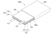
図2は、全固体リチウム二次電池の一例を示す模式図である。図2に示す全固体リチウム二次電池1000は、正極110と、負極120と、固体電解質層130とを有する積層体100と、積層体100を収容する外装体200と、を有する。また、全固体リチウム二次電池1000は、集電体の両側にCAMと負極活物質とを配置したバイポーラ構造であってもよい。バイポーラ構造の具体例として、例えば、JP-A-2004-95400に記載される構造が挙げられる。
Figure 2 is a schematic diagram showing an example of an all-solid-state lithium secondary battery. The all-solid-state lithium
正極110は、正極活物質層111と正極集電体112とを有している。正極活物質層111は、上述したCAM及び固体電解質を含む。また、正極活物質層111は、導電材及びバインダーを含んでいてもよい。
The
負極120は、負極活物質層121と負極集電体122とを有している。負極活物質層121は、負極活物質を含む。また、負極活物質層121は、固体電解質及び導電材を含んでいてもよい。
The
積層体100は、正極集電体112に接続される外部端子113と、負極集電体122に接続される外部端子123と、を有していてもよい。その他、全固体リチウム二次電池1000は、正極110と負極120との間にセパレータを有していてもよい。
The laminate 100 may have an
全固体リチウム二次電池1000は、さらに積層体100と外装体200とを絶縁する不図示のインシュレーター及び外装体200の開口部200aを封止する不図示の封止体を有する。
The all-solid-state lithium
外装体200は、アルミニウム、ステンレス鋼又はニッケルメッキ鋼などの耐食性の高い金属材料を成形した容器を用いることができる。また、外装体200として、少なくとも一方の面に耐食加工を施したラミネートフィルムを袋状に加工した容器を用いることもできる。
The
全固体リチウム二次電池1000の形状としては、例えば、コイン型、ボタン型、ペーパー型(またはシート型)、円筒型、角型、又はラミネート型(パウチ型)などの形状を挙げることができる。
The shape of the all-solid-state lithium
全固体リチウム二次電池1000は、一例として積層体100を1つ有する形態が図示されているが、本実施形態はこれに限らない。全固体リチウム二次電池1000は、積層体100を単位セルとし、外装体200の内部に複数の単位セル(積層体100)を封じた構成であってもよい。
The all-solid-state lithium
全固体リチウム二次電池については、例えば、WO2022/113904A1の[0151]~[0181]に記載の構成、材料及び製造方法を用いることができる。 For all-solid-state lithium secondary batteries, the configuration, materials, and manufacturing methods described in, for example, [0151] to [0181] of WO2022/113904A1 can be used.
<全細孔容積の測定方法>
前駆体の全細孔容積は、上記[全細孔容積の測定方法]に記載のとおり測定した。
<Method for measuring total pore volume>
The total pore volume of the precursor was measured as described above in [Method of measuring total pore volume].
<A/B>
上記[粉末X線回折測定]に記載の方法により、前駆体のA及びBをそれぞれ測定し、A/Bを算出した。
<A/B>
The precursors A and B were measured by the method described in the above [Powder X-ray diffraction measurement], and A/B was calculated.
<C/D50、C/D10、及びC/D90>
前駆体のCは、上記[平均細孔径の測定方法]により測定した。前駆体のD10、D50及びD90は、上記[粒度分布の測定方法]に記載のとおり測定した。得られた値から、C/D50、C/D10、及びC/D90をそれぞれ算出した。
<C/ D50 , C/ D10 , and C/ D90 >
The C of the precursor was measured by the above [Method for measuring average pore diameter]. The D 10 , D 50 and D 90 of the precursor were measured as described in the above [Method for measuring particle size distribution]. From the obtained values, C/D 50 , C/D 10 and C/D 90 were calculated, respectively.
<BET比表面積の測定方法>
前駆体のBET比表面積は、上記[BET比表面積の測定方法]に記載のとおり測定した。
<Method for measuring BET specific surface area>
The BET specific surface area of the precursor was measured as described in the above [Method of measuring BET specific surface area].
<組成分析>
前駆体の組成は、上記[組成分析]に記載の方法により測定した。
<Composition Analysis>
The composition of the precursor was measured by the method described in [Composition Analysis] above.
<前駆体の評価方法>
上記[前駆体の評価方法]に記載のとおり、リチウム二次電池を製造し、1CA/0.2CA放電容量比率と初回充放電効率を測定した。
<Precursor evaluation method>
As described in the above [Precursor evaluation method], a lithium secondary battery was produced, and the 1 CA/0.2 CA discharge capacity ratio and the initial charge/discharge efficiency were measured.
(実施例1)
攪拌器及びオーバーフローパイプを備えた反応槽内に水を入れた後、水酸化ナトリウム水溶液を添加し、液温を70℃に保持した。
Example 1
Water was placed in a reaction vessel equipped with a stirrer and an overflow pipe, and then an aqueous sodium hydroxide solution was added and the liquid temperature was maintained at 70°C.
硫酸ニッケル水溶液と硫酸コバルト水溶液とを混合して、第1金属塩溶液を調整した。また、第2金属塩溶液として硫酸アルミニウム水溶液を調整した。第1金属塩溶液と第2金属塩溶液を、NiとCoとAlとのモル比が0.88:0.09:0.03となる割合で連続的に反応槽に供給した。 A first metal salt solution was prepared by mixing an aqueous solution of nickel sulfate and an aqueous solution of cobalt sulfate. An aqueous solution of aluminum sulfate was also prepared as a second metal salt solution. The first metal salt solution and the second metal salt solution were continuously supplied to the reaction tank in a ratio such that the molar ratio of Ni, Co, and Al was 0.88:0.09:0.03.
同時に、反応槽内に、錯化剤として硫酸アンモニウム水溶液を供給し、アルカリ性水溶液として水酸化ナトリウム水溶液を供給した。このとき、第2金属塩溶液の供給量S1とアルカリ性水溶液の供給量S2との比(S1/S2)が、0.08となるように、各供給量を調整した。このとき、反応槽内の混合液のpHは11.51(測定温度:40℃)であった。 At the same time, an aqueous ammonium sulfate solution was supplied as a complexing agent into the reaction tank, and an aqueous sodium hydroxide solution was supplied as an alkaline aqueous solution. At this time, the amounts of the second metal salt solution and the alkaline aqueous solution were adjusted so that the ratio (S1/S2) of the amount of the second metal salt solution and the amount of the alkaline aqueous solution supplied was 0.08. At this time, the pH of the mixed solution in the reaction tank was 11.51 (measurement temperature: 40°C).
得られた反応沈殿物1を洗浄した後、脱水、乾燥及び篩別し、Ni、Co及びAlを含む金属複合水酸化物1を得た。
The resulting reaction precipitate 1 was washed, dehydrated, dried and sieved to obtain a
次に、200gの金属複合水酸化物1を、内寸120mm×120mm、高さ60mmの角型の鞘箱に収容し、金属複合水酸化物1の層厚を21mmとした。
金属複合水酸化物1を収容した鞘箱を酸化雰囲気焼成炉(モトヤマ社製、製品名:SKA-3050F-SP)に入れ、大気雰囲気下で500℃まで昇温した。
このとき、昇温開始から最高保持温度に到達し、降温が開始するまでに供給する大気の総流量を300L、即ち、金属複合水酸化物1の層厚/昇温開始から最高保持温度に到達し、降温が開始するまでに供給する大気の総流量(表1では、「金属複合水酸化物の層厚/大気の総流量」と記載)を0.070mm/Lとした。
昇温後、500℃の温度を維持し、5時間加熱した。
Next, 200 g of the
The sheath containing the
At this time, the total flow rate of air supplied from the start of the temperature increase until the maximum held temperature is reached and the temperature decrease is started was 300 L, in other words, the layer thickness of metal
After the temperature was increased, the temperature was maintained at 500° C. and heating was continued for 5 hours.
次に、大気雰囲気下で500℃から室温まで降温した。
このとき、降温開始から室温に到達するまでに供給する大気の総流量を300L、即ち、鞘箱(容器)内の粉体の層厚/降温開始から室温に到達するまでに供給する大気の総流量(表1では、「容器内粉体の層厚/大気の総流量」と記載)を0.070mm/Lとした。
これにより、前駆体1を得た。
Next, the temperature was lowered from 500° C. to room temperature in an air atmosphere.
At this time, the total flow rate of air supplied from the start of temperature drop until room temperature was reached was 300 L, that is, the powder layer thickness in the sheath (container)/total flow rate of air supplied from the start of temperature drop until room temperature was reached (referred to as "powder layer thickness in container/total flow rate of air" in Table 1) was 0.070 mm/L.
This gave
(実施例2~5)
酸化工程における条件を表1に記載のとおりに変更した以外は、実施例1と同様の方法により前駆体2~5を得た。
(Examples 2 to 5)
(比較例1)
金属複合水酸化物1をそのまま前駆体C1とした。
(Comparative Example 1)
(比較例2~4)
酸化工程における条件を表1に記載のとおりに変更した以外は、実施例1と同様の方法により前駆体C2~C4を得た。
(Comparative Examples 2 to 4)
Precursors C2 to C4 were obtained in the same manner as in Example 1, except that the conditions in the oxidation step were changed as shown in Table 1.
(比較例5)
40gの金属複合水酸化物1を、内寸120mm×120mm、高さ60mmの角型の鞘箱に収容し、金属複合水酸化物1の層厚を4.2mmとし、酸化工程における条件を表1に記載のとおりに変更した以外は、実施例1と同様の方法により前駆体C5を得た。
(Comparative Example 5)
Precursor C5 was obtained in the same manner as in Example 1, except that 40 g of metal
(比較例6)
S1/S2を0.13とし、反応槽内の混合液のpHが12.1(測定温度:40℃)に変更した以外は、実施例1と同様の方法で、Ni、Co及びAlを含む金属複合水酸化物2を得た。金属複合水酸化物2を前駆体C6とした。
(Comparative Example 6)
(比較例7)
250gの金属複合水酸化物2を、内寸120mm×120mm、高さ60mmの角型の鞘箱に収容し、金属複合水酸化物2の層厚を21mmとし、酸化工程における条件を表1に記載のとおりに変更した以外は、実施例1と同様の方法により前駆体C7を得た。
(Comparative Example 7)
Precursor C7 was obtained in the same manner as in Example 1, except that 250 g of metal
実施例1~5で得られた前駆体1~5、及び比較例1~7で得られた前駆体C1~C7の組成はいずれも、上記式(I)に対応して、y=0.09、z=0.03であった。
The compositions of
実施例1~5で得られた前駆体1~5、及び比較例1~7で得られた前駆体C1~C7について、以下の方法で、それぞれCAMを製造した。
前駆体に含まれるNi、Co及びAlの合計量1に対するLiの量(モル比)が1.02となる割合で水酸化リチウムを秤量した。前駆体と水酸化リチウムを混合して混合物を得た。
CAMs were produced from the
Lithium hydroxide was weighed out so that the amount of Li (molar ratio) was 1.02 relative to the total amount of Ni, Co, and Al contained in the precursor, which was 1. The precursor and lithium hydroxide were mixed to obtain a mixture.
この混合物を酸化雰囲気焼成炉(モトヤマ社製、製品名:SKA-3050F-SP)に投入し、650℃、保持時間を5時間とする条件で一次焼成した。 This mixture was placed in an oxidizing atmosphere firing furnace (manufactured by Motoyama Corporation, product name: SKA-3050F-SP) and subjected to primary firing at 650°C for a holding time of 5 hours.
一次焼成後、さらに酸化雰囲気焼成炉(モトヤマ社製、製品名:SKA-3050F-SP)に投入し、740℃、保持時間を5時間とする条件で二次焼成し、焼成物を得た。 After the primary firing, the mixture was placed in an oxidizing atmosphere firing furnace (manufactured by Motoyama Corporation, product name: SKA-3050F-SP) and subjected to secondary firing at 740°C for a holding time of 5 hours to obtain the fired product.
焼成物と液温を5℃に調整した純水とを、全体量に対して焼成物の重量の割合が50質量%になる割合で混合してスラリーを作製した。スラリーを20分間撹拌させて洗浄した後、脱水し、窒素雰囲気において210℃で10時間熱処理した。
これにより、CAMを得た。
The fired product was mixed with pure water whose temperature was adjusted to 5° C. in such a ratio that the weight ratio of the fired product to the total amount was 50 mass % to prepare a slurry. The slurry was stirred for 20 minutes and washed, then dehydrated and heat-treated at 210° C. for 10 hours in a nitrogen atmosphere.
This resulted in the production of a CAM.
表1に、実施例1~5、比較例1~7の製造条件をまとめて記載する。 The manufacturing conditions for Examples 1 to 5 and Comparative Examples 1 to 7 are summarized in Table 1.

表2に、実施例1~5、比較例1~7の前駆体の各物性、1CA/0.2CA放電容量比率及び初回充放電効率の結果をまとめて記載する。
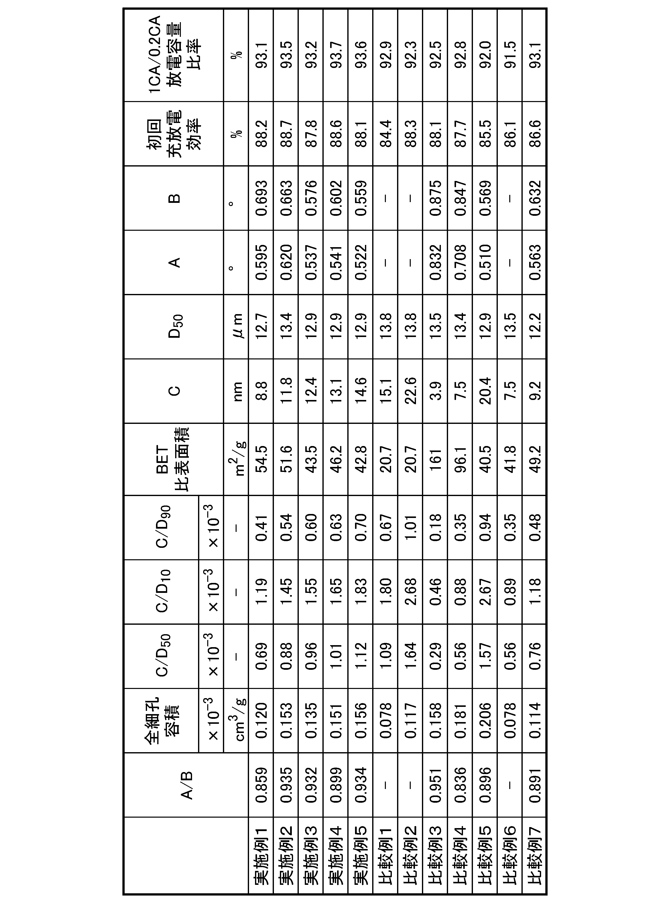
表2に記載の結果から、上記(1)及び(2)を満たす前駆体を原料として用いて製造したCAMを用いたリチウム二次電池は、放電レート特性と初回充放電効率が優れていた。 The results shown in Table 2 show that the lithium secondary battery using CAM manufactured using precursors that satisfy the above (1) and (2) as raw materials had excellent discharge rate characteristics and initial charge/discharge efficiency.
対して、比較例1、並びに比較例2~4、及び6は、実施例に比べて放電レート特性と初回充放電効率の一方、又は両方が低かった。これは、金属複合水酸化物のまま、又は酸化が不十分であるために、金属複合水酸化物と金属複合酸化物が混在しており、リチウムイオンが拡散されやすい結晶が形成されず、内部抵抗が増大したためと考えられる。 In contrast, in Comparative Example 1, as well as Comparative Examples 2 to 4 and 6, the discharge rate characteristics and/or initial charge/discharge efficiency were lower than in the Examples. This is thought to be because the metal composite hydroxides remained as they were, or were insufficiently oxidized, resulting in a mixture of metal composite hydroxides and metal composite oxides, which did not form crystals that would allow lithium ions to easily diffuse, and therefore increased internal resistance.
比較例5は、実施例に比べて放電レート特性と初回充放電効率が低かった。これは上記(A)及び(B)を満たさない条件であったため、酸化工程で金属複合水酸化物から十分に水が抜けず、細孔が十分に形成されなかったためと考えられる。 In Comparative Example 5, the discharge rate characteristics and initial charge/discharge efficiency were lower than in the Examples. This is thought to be because the conditions (A) and (B) above were not satisfied, and therefore water was not sufficiently removed from the metal composite hydroxide during the oxidation process, and pores were not sufficiently formed.
比較例7は、実施例に比べて初回充放電効率が低かった。これはS1/S2が0.13であったため、前駆体の結晶が特定面の方向に偏って成長できなかったためと考えられる。 Comparative Example 7 had a lower initial charge/discharge efficiency than the Examples. This is thought to be because S1/S2 was 0.13, and the precursor crystals were not able to grow biased in a specific plane direction.
1:セパレータ、2:正極、2a:正極活物質層、2b:正極集電体層、3:負極、4:電極群、5:電池缶、6:電解液、7:トップインシュレーター、8:封口体、10:リチウム二次電池、21:正極リード、31:負極リード、100:積層体、110:正極、111:正極活物質層、112:正極集電体、113:外部端子、120:負極、121:負極活物質層、122:負極集電体、123:外部端子、130:固体電解質層、200:外装体、200a:開口部、1000:全固体リチウム二次電池 1: separator, 2: positive electrode, 2a: positive electrode active material layer, 2b: positive electrode current collector layer, 3: negative electrode, 4: electrode group, 5: battery can, 6: electrolyte, 7: top insulator, 8: sealing body, 10: lithium secondary battery, 21: positive electrode lead, 31: negative electrode lead, 100: laminate, 110: positive electrode, 111: positive electrode active material layer, 112: positive electrode current collector, 113: external terminal, 120: negative electrode, 121: negative electrode active material layer, 122: negative electrode current collector, 123: external terminal, 130: solid electrolyte layer, 200: exterior body, 200a: opening, 1000: all-solid-state lithium secondary battery
Claims (9)
(1)窒素吸着等温線からBarrett-Joyner-Halenda(BJH)法により算出した細孔径分布において、細孔径が2nm以上200nm以下の範囲における全細孔容積が、0.115cm3/g以上0.180cm3/g以下である。
(2)0.84<A/B<0.95
(Aは、CuKα線源を使用した粉末X線回折測定において、2θ=37.5±1°の範囲内に存在する回折ピークの半値幅であり、Bは、2θ=43.5±1°の範囲内に存在する回折ピークの半値幅である。) A precursor for a positive electrode active material for a lithium secondary battery, the precursor containing at least Ni and one or more elements selected from the group consisting of Co and element M1, and satisfying the following (1) and (2):
(1) In the pore size distribution calculated from the nitrogen adsorption isotherm by the Barrett-Joyner-Halenda (BJH) method, the total pore volume in the pore size range of 2 nm or more and 200 nm or less is 0.115 cm 3 /g or more and 0.180 cm 3 /g or less.
(2) 0.84<A/B<0.95
(A is the half-width of a diffraction peak present within the range of 2θ=37.5±1° in powder X-ray diffraction measurement using a CuKα radiation source, and B is the half-width of a diffraction peak present within the range of 2θ=43.5±1°.)
(3)0.6×10⁻³≦C/D50≦1.6×10-3
(Cは、前記細孔径分布における平均細孔径(nm)であり、D50は、レーザー回折散乱法により測定される体積基準の累積粒度分布曲線から得られる50%累積体積粒度(μm)である。) The precursor according to claim 1 , which satisfies the following (3):
(3) 0.6×10 -3 ≦C/D 50 ≦1.6×10 -3
(C is the average pore diameter (nm) in the pore diameter distribution, and D50 is the 50% cumulative volume particle size (μm) obtained from a volume-based cumulative particle size distribution curve measured by a laser diffraction scattering method.)
(4)1.0×10⁻³≦C/D10≦2.5×10-3
(Cは、前記細孔径分布における平均細孔径(nm)であり、D10は、レーザー回折散乱法により測定される体積基準の累積粒度分布曲線から得られる10%累積体積粒度(μm)である。) The precursor according to claim 1 or 2, which satisfies the following (4).
(4) 1.0×10 -3 ≦C/D 10 ≦2.5×10 -3
(C is the average pore diameter (nm) in the pore diameter distribution, and D10 is the 10% cumulative volume particle size (μm) obtained from a volume-based cumulative particle size distribution curve measured by a laser diffraction scattering method.)
(5)0.4×10⁻³≦C/D90≦1.0×10-3
(Cは、前記細孔径分布における平均細孔径(nm)であり、D90は、レーザー回折散乱法により測定される体積基準の累積粒度分布曲線から得られる90%累積体積粒度(μm)である。) The precursor according to claim 1 or 2, which satisfies the following (5).
(5) 0.4×10 -3 ≦C/D 90 ≦1.0×10 -3
(C is the average pore diameter (nm) in the pore diameter distribution, and D 90 is the 90% cumulative volume particle size (μm) obtained from a volume-based cumulative particle size distribution curve measured by a laser diffraction scattering method.)
Ni:Co:M1=(1-y-z):y:z ・・・(I)
(M1は、Mn、Mg、Ca、Sr、Ba、Zn、B、Al、Ga、Ti、Zr、Ge、Fe、Cu、Cr、V、W、Mo、Sc、Y、Nb、La、Ta、Tc、Ru、Rh、Pd、Ag、Cd、In及びSnからなる群より選択される1種以上の元素である。式(I)は、0≦y≦0.4、0≦z≦0.5、及び0<y+zを満たす。) 3. The precursor according to claim 1 or 2, which satisfies the following formula (I):
Ni:Co:M1=(1-y-z):y:z...(I)
(M1 is one or more elements selected from the group consisting of Mn, Mg, Ca, Sr, Ba, Zn, B, Al, Ga, Ti, Zr, Ge, Fe, Cu, Cr, V, W, Mo, Sc, Y, Nb, La, Ta, Tc, Ru, Rh, Pd, Ag, Cd, In, and Sn. Formula (I) satisfies 0≦y≦0.4, 0≦z≦0.5, and 0<y+z.)
Priority Applications (1)
| Application Number | Priority Date | Filing Date | Title |
|---|---|---|---|
| JP2023148424A JP2025041245A (en) | 2023-09-13 | 2023-09-13 | A method for producing a precursor and a positive electrode active material for a lithium secondary battery. |
Applications Claiming Priority (1)
| Application Number | Priority Date | Filing Date | Title |
|---|---|---|---|
| JP2023148424A JP2025041245A (en) | 2023-09-13 | 2023-09-13 | A method for producing a precursor and a positive electrode active material for a lithium secondary battery. |
Publications (1)
| Publication Number | Publication Date |
|---|---|
| JP2025041245A true JP2025041245A (en) | 2025-03-26 |
Family
ID=95105078
Family Applications (1)
| Application Number | Title | Priority Date | Filing Date |
|---|---|---|---|
| JP2023148424A Pending JP2025041245A (en) | 2023-09-13 | 2023-09-13 | A method for producing a precursor and a positive electrode active material for a lithium secondary battery. |
Country Status (1)
| Country | Link |
|---|---|
| JP (1) | JP2025041245A (en) |
-
2023
- 2023-09-13 JP JP2023148424A patent/JP2025041245A/en active Pending
Similar Documents
| Publication | Publication Date | Title |
|---|---|---|
| CN104409700A (en) | Anode material for nickel-base lithium ion battery and preparation method of anode material | |
| JP7135354B2 (en) | Positive electrode active material precursor for non-aqueous electrolyte secondary battery, method for producing positive electrode active material precursor for non-aqueous electrolyte secondary battery, method for producing positive electrode active material for non-aqueous electrolyte secondary battery | |
| JP7353454B1 (en) | Lithium metal composite oxide, positive electrode active material for lithium secondary batteries, positive electrode for lithium secondary batteries, and lithium secondary batteries | |
| WO2023090452A1 (en) | Precursor powder, positive electrode active material powder, positive electrode active material powder production method, positive electrode, and lithium secondary battery | |
| JP2025041245A (en) | A method for producing a precursor and a positive electrode active material for a lithium secondary battery. | |
| JP2024053428A (en) | Lithium metal composite oxide, positive electrode active material for lithium secondary battery, positive electrode for lithium secondary battery, and lithium secondary battery | |
| JP7541152B1 (en) | Lithium metal composite oxide, positive electrode active material for lithium secondary battery, positive electrode for lithium secondary battery, and lithium secondary battery | |
| JP7441998B1 (en) | Lithium metal composite oxide, positive electrode active material for lithium secondary batteries, positive electrode for lithium secondary batteries, and lithium secondary batteries | |
| JP7454642B1 (en) | Lithium metal composite oxide, positive electrode active material for lithium secondary batteries, positive electrode for lithium secondary batteries, and lithium secondary batteries | |
| JP7441999B1 (en) | Lithium metal composite oxide, positive electrode active material for lithium secondary batteries, positive electrode for lithium secondary batteries, and lithium secondary batteries | |
| JP7483987B1 (en) | Lithium metal composite oxide, positive electrode active material for lithium secondary battery, positive electrode for lithium secondary battery, and lithium secondary battery | |
| JP7397156B1 (en) | Method for producing metal composite compound powder and positive electrode active material for lithium secondary batteries | |
| JP7412485B1 (en) | Method for producing metal composite hydroxide particles and positive electrode active material for lithium secondary batteries | |
| JP7417675B1 (en) | Metal composite hydroxide particles, method for producing metal composite compound, and method for producing positive electrode active material for lithium secondary batteries | |
| JP7359911B1 (en) | Precursor and method for producing positive electrode active material for lithium secondary batteries | |
| JP7416897B1 (en) | Lithium metal composite oxide, positive electrode active material for lithium secondary batteries, positive electrode for lithium secondary batteries, and lithium secondary batteries | |
| US20250296851A1 (en) | Metal composite compound and method of producing positive electrode active material for lithium secondary battery | |
| JP2025144404A (en) | METAL COMPOSITE COMPOUND AND METHOD FOR PRODUCING POSITIVE ELECTRODE ACTIVE MATERIAL FOR LITHIUM SECONDARY BATTERY | |
| WO2023106313A1 (en) | Positive electrode active material for lithium secondary batteries, positive electrode for lithium secondary batteries, and lithium secondary battery | |
| JP2025038616A (en) | Positive electrode active material for lithium secondary battery, positive electrode for lithium secondary battery, lithium secondary battery, and method for producing positive electrode active material for lithium secondary battery |
Legal Events
| Date | Code | Title | Description |
|---|---|---|---|
| A711 | Notification of change in applicant |
Free format text: JAPANESE INTERMEDIATE CODE: A711 Effective date: 20251215 |
|
| A521 | Request for written amendment filed |
Free format text: JAPANESE INTERMEDIATE CODE: A821 Effective date: 20251215 |