JP2025041243A - Retractable handle - Google Patents
Retractable handle Download PDFInfo
- Publication number
- JP2025041243A JP2025041243A JP2023148419A JP2023148419A JP2025041243A JP 2025041243 A JP2025041243 A JP 2025041243A JP 2023148419 A JP2023148419 A JP 2023148419A JP 2023148419 A JP2023148419 A JP 2023148419A JP 2025041243 A JP2025041243 A JP 2025041243A
- Authority
- JP
- Japan
- Prior art keywords
- arm
- base
- retractable handle
- stopper
- recess
- Prior art date
- Legal status (The legal status is an assumption and is not a legal conclusion. Google has not performed a legal analysis and makes no representation as to the accuracy of the status listed.)
- Pending
Links
Images

Landscapes
- Mechanical Control Devices (AREA)
Abstract
【課題】収納形態から簡単に操作形態として、窓の開閉のための回転操作中には、確実に起立状態で固定でき、起立状態の固定/解除の切替を容易に行うことができる収納式ハンドルを提供する。【解決手段】窓の開閉用オペレーター装置50の入力軸50aと一体回転する台座1と、台座1に対して起伏するアーム2と、アーム2の先端側に位置するツマミ3とを備え、アーム2を起こすと操作形態となり、アーム2を倒伏させると収納形態となる収納式ハンドルにおいて、アーム2は、台座1に接続されるクランク部21を有し、クランク部21の延伸方向に対して傾斜する平面上に設定された回動中心軸21bを中心として台座1に対し捻ることにより起伏するものとし、台座1に対するアーム2の捻りを阻止/許容するスイッチ4を備えた収納式ハンドルとする。【選択図】図1[Problem] To provide a retractable handle that can be easily changed from a stored state to an operating state, can be reliably fixed in an upright state during a rotation operation for opening or closing a window, and can easily be switched between fixed and released in the upright state. [Solution] The retractable handle includes a base 1 that rotates integrally with an input shaft 50a of a window opening/closing operator device 50, an arm 2 that rises and falls relative to the base 1, and a knob 3 located at the tip of the arm 2, and is in the operating state when the arm 2 is raised and in the stored state when the arm 2 is lowered. The arm 2 has a crank portion 21 connected to the base 1, and rises and falls by twisting relative to the base 1 around a rotation center axis 21b set on a plane that is inclined with respect to the extension direction of the crank portion 21, and is equipped with a switch 4 that prevents/allows the arm 2 to twist relative to the base 1. [Selected drawing] Figure 1
Description
この発明は、窓の開閉をするための収納式ハンドルに関するものである。 This invention relates to a retractable handle for opening and closing a window.
図5に示す窓Wの開閉用オペレーター装置50は、その入力軸50aと一体回転する台座51と、台座51から径方向に延びて起伏するアーム52と、アーム52の先端部に位置して台座51及びアーム52に対し相対回転するツマミ53とからなり、アーム52を引き起こすと操作形態となり、アーム52を倒伏させると収納形態となる収納式ハンドルを備えたものとされている。
The
このような機能を有する収納式ハンドルの一例として、下記特許文献1には、四節リンク機構から構成され、操作時にアームを起こすとツマミが操作者側に向き、収納時にアームを倒すとツマミがオペレーター装置の表面に沿うものが記載されている。
As an example of a retractable handle with this function, the following
また、下記特許文献2には、窓を開閉する操作形態時に、板ばねの圧接抵抗によりアームを起立状態に保持し、さらにロック片で板ばねを拘束することにより、アームの起立状態をより確実に保持する収納式ハンドルが記載されている。
In addition, the following
しかしながら、特許文献1に開示されたような収納式ハンドルでは、収納形態からアームを引き起こして操作形態とし、アームを連続回転させて窓を開閉する際に、意図せずアームの固定が解除され、アームが倒れてしまうことがあり、その場合、改めてアームを引き起こさなければならず、手間が掛かるという問題がある。
However, with a retractable handle such as that disclosed in
また、特許文献2に開示されたような収納式ハンドルでは、アームの起立状態を確実に保持するロック片が視認しづらく、アームの起立状態の保持/解除の切替において操作性が悪いという問題がある。
Furthermore, with a retractable handle such as that disclosed in
そこで、この発明は、収納形態から簡単に操作形態として、窓の開閉のための回転操作中には、確実に起立状態で固定でき、起立状態の固定/解除の切替を容易に行うことができる収納式ハンドルを提供することを課題とする。 The objective of this invention is to provide a retractable handle that can be easily switched from a retracted state to an operating state, can be reliably fixed in an upright state during rotational operations to open or close a window, and can easily be switched between fixed and released in the upright state.
上記課題を解決するため、この発明は、窓の開閉用オペレーター装置の入力軸と一体回転する台座と、前記台座に対して起伏するアームと、前記アームの先端側に位置するツマミとを備え、
前記アームを起こすと操作形態となり、前記アームを倒伏させると収納形態となる収納式ハンドルにおいて、
前記アームは、前記台座に接続されるクランク部を有し、前記クランク部の延伸方向に対して傾斜する平面上に設定された回動中心軸を中心として前記台座に対し捻ることにより起伏するものとされ、
前記台座に対する前記アームの捻りを阻止/許容するスイッチを備えていることを特徴とする収納式ハンドルを提供することとしたのである。
In order to solve the above problems, the present invention provides a window opening/closing operator device that includes a base that rotates integrally with an input shaft of the window opening/closing operator device, an arm that rises and falls relative to the base, and a knob located on the tip side of the arm,
A retractable handle that is in an operating mode when the arm is raised and in a retractable mode when the arm is lowered,
the arm has a crank portion connected to the base, and rises and falls by twisting with respect to the base about a rotation central axis set on a plane inclined with respect to an extension direction of the crank portion,
The object is to provide a retractable handle characterized by including a switch for preventing/allowing twisting of the arm relative to the base.
そして、前記台座は、前記オペレーター装置の入力軸に結合される基部の外周に、前記基部の軸線と交差する方向へ突出するアーム受部が設けられた形状とされ、
前記台座のアーム受部と前記アームのクランク部とは、互いの傾斜端面を突き合わせて回動自在に接合され、
前記アームの捻りに伴い、前記アーム受部の傾斜端面に対して前記アームの傾斜端面が摺動して、前記アームが起伏するものとしたのである。
The base is shaped such that an arm receiving portion is provided on an outer periphery of a base portion coupled to an input shaft of the operator device, the arm receiving portion protruding in a direction intersecting with an axis of the base portion,
The arm receiving portion of the base and the crank portion of the arm are joined to each other so as to be rotatable by butting their inclined end surfaces against each other,
As the arm is twisted, the inclined end surface of the arm slides against the inclined end surface of the arm receiving portion, causing the arm to rise and fall.
また、前記アームは、前記台座に対して、完全に起立した位置と、完全に倒伏した位置とで、捻りの阻止/許容の切替が可能になるものとしたのである。 The arm can also be adjusted to prevent or allow twisting between a fully upright position and a fully reclined position relative to the base.
また、前記スイッチは、前記アームに設けられたものであって、前記台座の凹所に係脱するストッパーの操作部材とされ、
前記ストッパーが前記凹所に係合することにより、前記アームの捻りが阻止され、前記ストッパーが前記凹所から離脱することにより、前記アームの捻りが許容されるものとしたのである。
The switch is provided on the arm and serves as an operating member for a stopper that engages with and disengages from a recess in the base,
When the stopper engages with the recess, twisting of the arm is prevented, and when the stopper disengages from the recess, twisting of the arm is permitted.
さらに、前記スイッチ及び前記ストッパーは、前記台座の凹所に嵌り込む方向へ付勢されており、
前記アームを起伏させる際には、前記スイッチを付勢力に抗して前記ストッパーが前記凹所から離脱するように操作し、前記アームが捻りに伴い完全に起立又は倒伏すると、前記ストッパーが付勢力で前記凹所に自動的に嵌まり込むものとしたのである。
Furthermore, the switch and the stopper are biased in a direction to be fitted into the recess of the base,
When the arm is to be raised or lowered, the switch is operated against the biasing force so that the stopper disengages from the recess, and when the arm is fully raised or lowered by twisting, the stopper is automatically fitted into the recess by the biasing force.
また、前記アームは、前記台座に接続されるクランク部に、前記ツマミが回動自在に接続されるツマミ接続部が連なるものとしたのである。 The arm also has a crank portion connected to the base, and a knob connection portion to which the knob is rotatably connected.
この発明に係る収納式ハンドルでは、スイッチを操作してアームの捻りが許容された状態とすれば、アームをそのクランク部の軸線を中心として台座に対し捻るだけで、簡単に起伏させることができるので、アームを倒伏した収納形態から迅速に起立させて操作形態とすることができる。 In the retractable handle of this invention, if the switch is operated to allow the arm to twist, the arm can be easily raised and lowered by simply twisting it around the axis of the crank portion relative to the base, so the arm can be quickly raised from the collapsed storage position to the operating position.
そして、窓の開閉のためのアームの回転操作中には、スイッチによりアームの倒伏が阻止されるので、アームが確実に起立状態で固定され、安定した操作形態で連続的にアームを回転させて、窓を開閉することができる。 The switch prevents the arm from falling over while it is being rotated to open or close the window, so the arm is securely fixed in an upright position, allowing the arm to be rotated continuously in a stable operating form to open and close the window.
また、簡単な操作でアームが起立した操作形態から倒伏した収納形態に切り替えることができ、収納形態において、アームとツマミとをオペレーター装置に沿わせ、スマートな外観を呈するものとすることができる。 In addition, the arm can be easily switched from an upright operating position to a tilted storage position, and in the storage position, the arm and knob can be aligned with the operator device, giving it a smart appearance.
<実施形態の構成>
(全体構成概要)
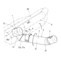
図1乃至図3に示すように、この収納式ハンドルHは、縦すべり出し窓等の開閉に適用されるものであり、オペレーター装置50の入力軸50aと一体回転する台座1と、台座1から径方向に延びて起伏するアーム2と、アーム2の先端側に位置するツマミ3とを主体として構成される。アーム2には、その起伏の可否を切り替える半環状のスイッチ4が設けられている。
<Configuration of the embodiment>
(Overall configuration overview)
1 to 3, this retractable handle H is applied to opening and closing vertical sliding windows and the like, and is mainly composed of a
(各部構成及び機能)
台座1は、オペレーター装置50の入力軸50aに結合される円柱状の基部11の外周に、基部11の軸線と交差する方向へ突出するアーム受部12が設けられた形状とされている。基部11には、外周から固定ねじ13がねじ込まれ、これにより台座1がオペレーター装置50の入力軸50aに固定されている。アーム受部12には、オペレーター装置50から離れるに従い基部11に近づく傾斜端面12aが形成されている。
(Components and functions)
The
アーム2は、長い丸棒状のクランク部21の先端に、屈曲部を介して短い丸棒状のツマミ接続部22が連なる形状とされている。クランク部21の基部側には、台座1のアーム受部12の傾斜端面12aに対応する傾斜端面21aが形成され、ツマミ接続部22の先端から凸軸22aが突出している。クランク部21及びツマミ接続部22の断面形状は、収納形態で嵩張らないように、僅かに偏平な円形とされている。
The
なお、クランク部21の断面形状を偏平な円形とすることにより、傾斜端面12a,21aを真円に近づけることが可能となる。これにより、アーム2の操作形態と収納形態の中間位置において、傾斜端面12a,21aの互いの面がずれる外観上の違和感を解消することが可能であり、後述のスイッチ4によるアーム2の捻りの阻止/許容の切替において、アーム2の操作形態と収納形態の中間位置でスイッチ4がアーム受部12の外周面に干渉して、アーム2の捻りが意図せず阻止されることを防止することが可能である。
By making the cross-sectional shape of the
ツマミ3は、短い円柱状とされ、基端面に開口する軸穴を有し、ツマミ接続部22の凸軸22aがツマミ台座31(図4参照)を介し軸穴に挿入されて、アーム2に回転自在に連結されている。
The
台座1のアーム受部12とアーム2のクランク部21とは、互いの軸線に対し傾斜する傾斜端面12a,21aを突き合わせ、ワッシャ6を介して連結ねじ5により回動自在に接合されている。そして、クランク部21の傾斜端面21aの中心を通りその法線方向を向く回動中心軸21bを中心として台座1に対しアーム2を捻ることにより、アーム受部12の傾斜端面12aに対してクランク部21の傾斜端面21aが摺動して、アーム2が起伏するようになっている。
The
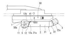
これに伴い、図2に示すように、窓Wを開閉する際、アーム2を起こすと、ツマミ3の回動中心である凸軸22aの軸線がオペレーター装置50の入力軸50aの軸線と平行になって操作形態となり、図3に示すように、アーム2を180°捻って倒伏させると、アーム2とツマミ3がオペレーター装置50の本体に沿った収納形態となる。
As a result, as shown in Figure 2, when opening or closing the window W, when the
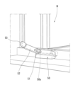
また、アーム2が台座1に対して完全に起立した位置において、ツマミ3の回動中心である凸軸22aは、オペレーター装置50の入力軸50aと平行であり、アーム2が台座1に対して完全に倒伏した位置において、ツマミ3の回動中心である凸軸22aは、オペレーター装置50の入力軸50aから離れるにつれ、窓Wに近接するように傾斜する。このため、図3に示す収納形態において、収納式ハンドルHはスマートな外観を呈するものとなる。
When the
さらに、このような収納式ハンドルHは、収納形態において、オペレーター装置50からあまり出っ張らないので、窓Wに沿って昇降するロールカーテン等と干渉しにくく、また、窓Wからの眺望を妨げにくいものとなる。
Furthermore, since this type of retractable handle H does not protrude too much from the
(スイッチ機構)
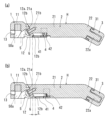
図4に示すように、スイッチ4は、クランク部21の軸線方向にスライド自在とされ、台座1のアーム受部12に形成された凹所12bへ向かうストッパー41が連結されたものとされている。
(Switch mechanism)
As shown in FIG. 4, the
凹所12bは、アーム受部12の傾斜端面12aにおける基部11に最も近い部分と、基部11から最も遠い部分とに臨んで、2か所に位置している。
The
ストッパー41は、スイッチ4とともにクランク部21の軸線方向にスライドし、ばね42により、先端部が凹所12bに嵌まり込む方向へ付勢されている。
The
このようなスイッチ機構によると、図4(a)に示すように、ストッパー41が凹所12bに嵌り込んで係合した状態では、アーム2の捻りが阻止され、アーム2を起伏させることができない。
With this type of switch mechanism, as shown in FIG. 4(a), when the
一方、図4(b)に示すように、スイッチ4を付勢力に抗して、凹所12bの深さに相当するストロークSを超えてツマミ3側へ引っ張るように操作すると、ストッパー41が凹所12bから抜け出すように離脱して、アーム2の捻りが許容され、アーム2を起伏させることができるようになる。
On the other hand, as shown in FIG. 4(b), when the
このため、アーム2は、台座1に対して完全に起立した位置と、完全に倒伏した位置とで、スイッチ4による捻りの阻止/許容の切替が可能とされ、その間の位置では、スイッチ4による捻りの阻止/許容の切替ができず、捻りが常に許容される。
As a result, the
従って、スイッチ4を操作してアーム2の捻りが許容された状態とし、アーム2をクランク部21の軸線を中心として捻ると、ストッパー41の先端部が凹所12bに一致した時点で、ストッパー41がばね42の付勢力により自動的に凹所12bに嵌まり込んで、アーム2の捻りが阻止され、アーム2は、台座1に対して完全に起立した位置又は完全に倒伏した位置で固定される。
Therefore, when the
<効果>
上記のような収納式ハンドルHでは、図1に示すように、スイッチ4を操作してアーム2の捻りが許容された状態とすれば、アーム2をそのクランク部21の軸線を中心として台座1に対し捻るだけで、簡単に起伏させることができるので、アーム2を倒伏した収納形態から迅速に起立させて操作形態とすることができる。
<Effects>
In the above-described retractable handle H, as shown in FIG. 1, by
そして、図2に示すように、ストッパー41が一方の凹所12bに係合すると、窓Wの開閉のためのアーム2の回転操作中には、台座1に対するアーム2の捻りが阻止されて、アーム2の倒伏が阻止されるので、アーム2が確実に起立状態で固定され、安定した操作形態で連続的にアーム2を回転させて、窓Wを開閉することができる。
As shown in FIG. 2, when the
また、図3に示すように、窓Wの開閉をしないときには、アーム2を完全に倒伏させて収納形態とし、ストッパー41を他方の凹所12bに係合させると、アーム2をオペレーター装置50の表面に沿って嵩張らないように固定できる。
Also, as shown in FIG. 3, when the window W is not to be opened or closed, the
<その他>
この収納式ハンドルHの台座1及びアーム2は、ガラス繊維入りのポリアミド等の合成樹脂製とするほか、ダイカスト製としてもよい。また、ツマミ3は、ポリアミド等の合成樹脂製とすればよく、ツマミ台座31、スイッチ4、ストッパー41は、ポリアセタール等の剛性及び耐摩耗性に優れた合成樹脂製とするとよい。
<Other>
The
また、この収納式ハンドルHを適用する窓Wは、縦すべり出し窓のほか、横すべり出し窓、その他ヒンジを軸に開閉する開き窓であってもよい。 The window W to which this retractable handle H is applied may be a vertical sliding window, a horizontal sliding window, or any other casement window that opens and closes on a hinge.
なお、上記実施形態では、スイッチ4として、アーム2のクランク部21の軸線方向にスライドさせるものを例示したが、スイッチ4は、クランク部21の径方向に出没する押しボタン式としてもよい。この場合、スイッチ4を突出方向に付勢して、ストッパー41を備えたものとしておき、台座1のアーム受部12には、クランク部21との接合面に凹所12bを有する周溝を形成する。
In the above embodiment, the
これにより、スイッチ4が突出した状態では、ストッパー41が凹所12bに係合してアーム2の捻りが阻止され、スイッチ4が付勢力に抗し押し込まれて没入した状態では、ストッパー41が凹所12bから離脱して周溝内を回転移動することにより、アーム2の捻りが許容されるものとなる。
As a result, when the
今回開示された実施形態はすべての点で例示であって制限的なものではないと考えられるべきである。したがって、本発明の範囲は特許請求の範囲によって示され、特許請求の範囲と均等の意味および範囲内でのすべての変更が含まれることが意図される。 The embodiments disclosed herein should be considered to be illustrative and not restrictive in all respects. Therefore, the scope of the present invention is defined by the claims, and it is intended to include all modifications within the scope and meaning equivalent to the claims.
例えば、クランク部21の台座1に対する捻り角度は、180°に限定されるものではなく、例えば90°、150°など任意に設定することができる。
For example, the twist angle of the
また、アーム2の台座1に対する捻りの阻止/許容の切替が可能とされるのが、「完全に起立した位置」と、「完全に倒伏した位置」としたが、この位置のみに厳密に限定されることを意図するものではなく、ストッパー41と凹所12bの捻り方向幅の加工バラツキを許容するために設けたバックラッシュ等による微小なグラつき等は当然許容される。
In addition, although it has been stated that the "fully erect position" and "fully reclined position" are the positions at which it is possible to switch between preventing and allowing twisting of the
H 収納式ハンドル
1 台座
2 アーム
3 ツマミ
4 スイッチ
5 連結ねじ
6 ワッシャ
11 基部
12 アーム受部
12a 傾斜端面
12b 凹所
13 固定ねじ
21 クランク部
21a 傾斜端面
21b 回動中心軸
22 ツマミ接続部
22a 凸軸
31 ツマミ台座
41 ストッパー
42 ばね
50 オペレーター装置
50a 入力軸
W 窓
H Retractable handle 1
Claims (6)
前記アーム(2)を起こすと操作形態となり、前記アーム(2)を倒伏させると収納形態となる収納式ハンドルにおいて、
前記アーム(2)は、前記台座(1)に接続されるクランク部(21)を有し、前記クランク部(21)の延伸方向に対して傾斜する平面上に設定された回動中心軸(21b)を中心として前記台座(1)に対し捻ることにより起伏するものとされ、
前記台座(1)に対する前記アーム(2)の捻りを阻止/許容するスイッチ(4)を備えていることを特徴とする収納式ハンドル。 The device comprises a base (1) that rotates integrally with an input shaft of an operator device for opening and closing a window, an arm (2) that rises and falls relative to the base (1), and a knob (3) located on the tip side of the arm (2),
A retractable handle that is in an operating mode when the arm (2) is raised and in a stored mode when the arm (2) is lowered,
the arm (2) has a crank portion (21) connected to the base (1), and rises and falls when twisted relative to the base (1) around a rotation central axis (21b) set on a plane inclined with respect to the extension direction of the crank portion (21);
A retractable handle characterized by comprising a switch (4) for preventing/allowing twisting of the arm (2) relative to the base (1).
前記台座(1)のアーム受部(12)と前記アーム(2)のクランク部(21)とは、互いの傾斜端面(12a,21a)を突き合わせて回動自在に接合され、
前記アーム(2)の捻りに伴い、前記アーム受部(12)の傾斜端面(12a)に対して前記アーム(21)の傾斜端面(21a)が摺動して、前記アーム(2)が起伏することを特徴とする請求項1に記載の収納式ハンドル。 The base (1) is shaped such that an arm receiving portion (12) protruding in a direction intersecting with the axis of the base (11) is provided on the outer periphery of the base (11) which is coupled to the input shaft of the operator device,
The arm receiving portion (12) of the base (1) and the crank portion (21) of the arm (2) are joined to each other so as to be rotatable by butting their inclined end faces (12a, 21a) against each other,
The retractable handle according to claim 1, characterized in that, as the arm (2) is twisted, the inclined end surface (21a) of the arm (21) slides against the inclined end surface (12a) of the arm receiving portion (12), causing the arm (2) to rise and fall.
前記ストッパー(41)が前記凹所(12b)に係合することにより、前記アーム(2)の捻りが阻止され、前記ストッパー(41)が前記凹所(12b)から離脱することにより、前記アーム(2)の捻りが許容されることを特徴とする請求項2又は3に記載の収納式ハンドル。 The switch (4) is provided on the arm (2) and serves as an operating member for a stopper (41) that engages with and disengages from a recess (12b) formed in the base (1);
A retractable handle as described in claim 2 or 3, characterized in that the stopper (41) engages with the recess (12b) to prevent twisting of the arm (2), and the stopper (41) disengages from the recess (12b) to allow twisting of the arm (2).
前記アーム(2)を起伏させる際には、前記スイッチ(4)を付勢力に抗して前記ストッパー(41)が前記凹所(12b)から離脱するように操作し、前記アーム(2)が捻りに伴い完全に起立又は倒伏すると、前記ストッパー(41)が付勢力で前記凹所(12b)に自動的に嵌まり込むことを特徴とする請求項4に記載の収納式ハンドル。 The switch (4) and the stopper (41) are biased in a direction to be fitted into the recess (12b) of the base (1),
A retractable handle as described in claim 4, characterized in that, when the arm (2) is raised or lowered, the switch (4) is operated against the biasing force so that the stopper (41) is removed from the recess (12b), and when the arm (2) is completely raised or lowered by twisting, the stopper (41) is automatically fitted into the recess (12b) by the biasing force.
Priority Applications (1)
| Application Number | Priority Date | Filing Date | Title |
|---|---|---|---|
| JP2023148419A JP2025041243A (en) | 2023-09-13 | 2023-09-13 | Retractable handle |
Applications Claiming Priority (1)
| Application Number | Priority Date | Filing Date | Title |
|---|---|---|---|
| JP2023148419A JP2025041243A (en) | 2023-09-13 | 2023-09-13 | Retractable handle |
Publications (1)
| Publication Number | Publication Date |
|---|---|
| JP2025041243A true JP2025041243A (en) | 2025-03-26 |
Family
ID=95105049
Family Applications (1)
| Application Number | Title | Priority Date | Filing Date |
|---|---|---|---|
| JP2023148419A Pending JP2025041243A (en) | 2023-09-13 | 2023-09-13 | Retractable handle |
Country Status (1)
| Country | Link |
|---|---|
| JP (1) | JP2025041243A (en) |
-
2023
- 2023-09-13 JP JP2023148419A patent/JP2025041243A/en active Pending
Similar Documents
| Publication | Publication Date | Title |
|---|---|---|
| US6427334B2 (en) | Folding knife with blade locking mechanism | |
| JP5695547B2 (en) | Furniture hinges with utensils | |
| CA2533091C (en) | Extension arm for a free arm parasol, pivotably arranged on a carrier | |
| EP1842995B1 (en) | Side lock assembly for storage bin | |
| US9908245B1 (en) | Locking mechanism for a folding instrument | |
| US3930309A (en) | Ring lock knife | |
| US5513510A (en) | Handleset with thumb piece and rack | |
| US20010036265A1 (en) | Automatic opening and closing apparatus for mobile phones | |
| JP2025041243A (en) | Retractable handle | |
| JP4173185B1 (en) | Mobile device | |
| CA2382943A1 (en) | Door holder assembly | |
| US20250351960A1 (en) | Anti-pinch device | |
| JP7202108B2 (en) | Locking device for folding worktables | |
| EP1787941A1 (en) | Corkscrew | |
| EP2300866A1 (en) | Spectacles having retractable sidepieces | |
| US1076568A (en) | Spring-hinge. | |
| JPS61122047A (en) | Manual adjusting device for retractable mirror | |
| CN216553468U (en) | Door connecting hinge and car | |
| CN110306893B (en) | Hinge with limiting and unlocking functions | |
| JP5474650B2 (en) | Cover for hinge | |
| KR200275876Y1 (en) | Hinge for a furniture | |
| JPH07229354A (en) | Hinge provided with function for holding intermediate open degree | |
| CN113434015B (en) | Rotary connecting structure | |
| SK285132B6 (en) | Switch | |
| JPH0245412Y2 (en) |