JP2025041233A - Reactor - Google Patents

Reactor Download PDF

Info

Publication number
JP2025041233A
JP2025041233A JP2023148407A JP2023148407A JP2025041233A JP 2025041233 A JP2025041233 A JP 2025041233A JP 2023148407 A JP2023148407 A JP 2023148407A JP 2023148407 A JP2023148407 A JP 2023148407A JP 2025041233 A JP2025041233 A JP 2025041233A
Authority
JP
Japan
Prior art keywords
reaction vessel
fluid
reaction
temperature
end side
Prior art date
Legal status (The legal status is an assumption and is not a legal conclusion. Google has not performed a legal analysis and makes no representation as to the accuracy of the status listed.)
Pending
Application number
JP2023148407A
Other languages
Japanese (ja)
Inventor
直樹 植田
Naoki Ueda
靖也 平松
Seiya Hiramatsu
賢一 古木
Kenichi Furuki
諭 中村
Satoshi Nakamura
Current Assignee (The listed assignees may be inaccurate. Google has not performed a legal analysis and makes no representation or warranty as to the accuracy of the list.)
Japan Steel Works Ltd
Original Assignee
Japan Steel Works Ltd
Priority date (The priority date is an assumption and is not a legal conclusion. Google has not performed a legal analysis and makes no representation as to the accuracy of the date listed.)
Filing date
Publication date
Application filed by Japan Steel Works Ltd filed Critical Japan Steel Works Ltd
Priority to JP2023148407A priority Critical patent/JP2025041233A/en
Priority to CN202480057811.7A priority patent/CN121843763A/en
Priority to PCT/JP2024/019131 priority patent/WO2025057487A1/en
Priority to TW113123050A priority patent/TW202510955A/en
Publication of JP2025041233A publication Critical patent/JP2025041233A/en
Pending legal-status Critical Current

Links

Images

Classifications

    • BPERFORMING OPERATIONS; TRANSPORTING
    • B01PHYSICAL OR CHEMICAL PROCESSES OR APPARATUS IN GENERAL
    • B01JCHEMICAL OR PHYSICAL PROCESSES, e.g. CATALYSIS OR COLLOID CHEMISTRY; THEIR RELEVANT APPARATUS
    • B01J19/00Chemical, physical or physico-chemical processes in general; Their relevant apparatus
    • BPERFORMING OPERATIONS; TRANSPORTING
    • B01PHYSICAL OR CHEMICAL PROCESSES OR APPARATUS IN GENERAL
    • B01JCHEMICAL OR PHYSICAL PROCESSES, e.g. CATALYSIS OR COLLOID CHEMISTRY; THEIR RELEVANT APPARATUS
    • B01J19/00Chemical, physical or physico-chemical processes in general; Their relevant apparatus
    • B01J19/18Stationary reactors having moving elements inside
    • FMECHANICAL ENGINEERING; LIGHTING; HEATING; WEAPONS; BLASTING
    • F27FURNACES; KILNS; OVENS; RETORTS
    • F27BFURNACES, KILNS, OVENS OR RETORTS IN GENERAL; OPEN SINTERING OR LIKE APPARATUS
    • F27B7/00Rotary-drum furnaces, i.e. horizontal or slightly inclined
    • F27B7/20Details, accessories or equipment specially adapted for rotary-drum furnaces
    • F27B7/34Arrangements of heating devices
    • FMECHANICAL ENGINEERING; LIGHTING; HEATING; WEAPONS; BLASTING
    • F27FURNACES; KILNS; OVENS; RETORTS
    • F27BFURNACES, KILNS, OVENS OR RETORTS IN GENERAL; OPEN SINTERING OR LIKE APPARATUS
    • F27B7/00Rotary-drum furnaces, i.e. horizontal or slightly inclined
    • F27B7/20Details, accessories or equipment specially adapted for rotary-drum furnaces
    • F27B7/36Arrangements of air or gas supply devices
    • FMECHANICAL ENGINEERING; LIGHTING; HEATING; WEAPONS; BLASTING
    • F27FURNACES; KILNS; OVENS; RETORTS
    • F27DDETAILS OR ACCESSORIES OF FURNACES, KILNS, OVENS OR RETORTS, IN SO FAR AS THEY ARE OF KINDS OCCURRING IN MORE THAN ONE KIND OF FURNACE
    • F27D11/00Arrangement of elements for electric heating in or on furnaces
    • FMECHANICAL ENGINEERING; LIGHTING; HEATING; WEAPONS; BLASTING
    • F27FURNACES; KILNS; OVENS; RETORTS
    • F27DDETAILS OR ACCESSORIES OF FURNACES, KILNS, OVENS OR RETORTS, IN SO FAR AS THEY ARE OF KINDS OCCURRING IN MORE THAN ONE KIND OF FURNACE
    • F27D19/00Arrangements of controlling devices
    • FMECHANICAL ENGINEERING; LIGHTING; HEATING; WEAPONS; BLASTING
    • F27FURNACES; KILNS; OVENS; RETORTS
    • F27DDETAILS OR ACCESSORIES OF FURNACES, KILNS, OVENS OR RETORTS, IN SO FAR AS THEY ARE OF KINDS OCCURRING IN MORE THAN ONE KIND OF FURNACE
    • F27D7/00Forming, maintaining or circulating atmospheres in heating chambers
    • F27D7/02Supplying steam, vapour, gases or liquids

Landscapes

  • Engineering & Computer Science (AREA)
  • Mechanical Engineering (AREA)
  • General Engineering & Computer Science (AREA)
  • Chemical & Material Sciences (AREA)
  • Organic Chemistry (AREA)
  • Chemical Kinetics & Catalysis (AREA)
  • Physical Or Chemical Processes And Apparatus (AREA)
  • Muffle Furnaces And Rotary Kilns (AREA)
  • Furnace Details (AREA)

Abstract

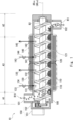
To provide a reaction apparatus capable of being prevented from an abnormal operation caused by deformation of a reaction vessel due to thermal expansion or thermal contraction.SOLUTION: A reaction apparatus 10 includes: a cylindrical reaction vessel including an intermediate part between a supply part and a delivery part; a plurality of heating parts arranged around a long axis of the reaction vessel so as to surround the intermediate part; a temperature control part for individually controlling a temperature of the plurality of heating parts; the supply part for supplying processed products to the reaction vessel; the delivery part for delivering product materials from the reaction vessel; a transportation mechanism for transporting the processed products to the delivery part side of the reaction vessel by passing the intermediate part from the supply part side of the reaction vessel; a fluid supply port and a fluid discharge port communicated to a space between the plurality of heating parts and the reaction vessel; and a fluid supply part for supplying fluid supplied from the fluid supply port to the space, passing the space, and discharged from the fluid discharge port.SELECTED DRAWING: Figure 19

Description

本発明は、反応装置に関する。 The present invention relates to a reaction apparatus.

粉粒体状の処理物に対して所定の雰囲気を与えることにより所望の製品を製造するための反応装置が存在する。例えば一般には、ロータリーキルンと称される反応装置は、中心軸周りに回転する中空の反応容器を加熱し、この反応容器に材料を転動させながら通過させることにより所望の製品を製造する。また例えばローラーハースキルンと称される反応装置は、トンネル型の反応容器に処理物やワークを通過させることにより所望の製品を製造する。またその他にも種々の反応装置が開発されている。 There are reactors that produce desired products by providing a specific atmosphere to powdered or granular materials to be processed. For example, a reactor known as a rotary kiln generally produces the desired product by heating a hollow reaction vessel that rotates around a central axis and passing the material through the reaction vessel while rolling it. Another reactor known as a roller hearth kiln produces the desired product by passing the material or workpiece through a tunnel-shaped reaction vessel. Various other reactors have also been developed.

例えば特許文献1は、以下の反応装置について開示している。反応装置は、圧力反応容器となるスクリュフィーダ本体と、スクリュフィーダ本体内に触媒を導入する触媒供給部と、スクリュフィーダ本体内に低級炭化水素を導入する低級炭化水素供給部と、を有する。またこの反応装置は、生成したナノ炭素を搬送するスクリュと、スクリュによって搬送される触媒とナノ炭素を送出する固体送出部と、生成した水素をフィーダ本体外に送出する気体送出部と、を有する。 For example, Patent Document 1 discloses the following reaction apparatus. The reaction apparatus has a screw feeder body that serves as a pressure reaction vessel, a catalyst supply section that introduces a catalyst into the screw feeder body, and a lower hydrocarbon supply section that introduces lower hydrocarbons into the screw feeder body. This reaction apparatus also has a screw that transports the generated nanocarbon, a solid delivery section that delivers the catalyst and nanocarbon transported by the screw, and a gas delivery section that delivers the generated hydrogen outside the feeder body.

特開2006-290682号公報JP 2006-290682 A

しかしながら、このような反応装置においては、反応容器の温度を変化させると、反応容器や搬送機構等が熱膨張もしくは熱収縮により変形し、反応装置の正常な動作を妨げるという課題がある。 However, in such a reaction device, when the temperature of the reaction vessel is changed, the reaction vessel or the transport mechanism, etc., are deformed due to thermal expansion or contraction, which hinders the normal operation of the reaction device.

その他の課題と新規な特徴は、本明細書の記述及び添付図面から明らかになるであろう。 Other objects and novel features will become apparent from the description of this specification and the accompanying drawings.

一実施の形態に係る反応装置は、供給部と送出部との間の中間部を含む筒状の反応容器と、前記中間部を囲むように当該反応容器の長軸周りに配置された複数の加熱部と、前記複数の加熱部の温度を個別に制御する温度制御部と、前記反応容器に処理物を供給する前記供給部と、前記反応容器から生成物を送出する前記送出部と、前記処理物を前記反応容器の前記供給部側から前記中間部を通過して前記反応容器の前記送出部側に搬送する搬送機構と、前記複数の加熱部と前記反応容器との間の空間に連通する流体供給口及び流体排出口と、前記流体供給口から前記空間に供給され当該空間を通過し前記流体排出口から排出される流体を供給する流体供給部と、を備える。 The reaction apparatus according to one embodiment includes a cylindrical reaction vessel including an intermediate portion between a supply portion and a discharge portion, a plurality of heating portions arranged around the longitudinal axis of the reaction vessel so as to surround the intermediate portion, a temperature control portion for individually controlling the temperatures of the plurality of heating portions, the supply portion for supplying a processing material to the reaction vessel, the discharge portion for discharging a product from the reaction vessel, a transport mechanism for transporting the processing material from the supply portion side of the reaction vessel through the intermediate portion to the discharge portion side of the reaction vessel, a fluid supply port and a fluid discharge port communicating with the space between the plurality of heating portions and the reaction vessel, and a fluid supply portion for supplying a fluid that is supplied from the fluid supply port to the space, passes through the space, and is discharged from the fluid discharge port.

本開示によれば、反応容器や搬送機構等が熱膨張もしくは熱収縮により変形しても、これに起因して正常に動作できなくなるのを防止することができる反応装置を提供することができる。 According to the present disclosure, it is possible to provide a reaction device that can prevent a reaction vessel, a transport mechanism, etc. from being unable to operate normally due to deformation caused by thermal expansion or contraction.

実施の形態1にかかる反応装置の側面図である。FIG. 2 is a side view of the reaction apparatus according to the first embodiment. 実施の形態1にかかる反応装置のブロック図である。FIG. 1 is a block diagram of a reaction apparatus according to a first embodiment. 反応装置が実行する処理のフローチャートである。1 is a flowchart of a process performed by a reaction device. 実施の形態2にかかる反応装置の側面図である。FIG. 11 is a side view of a reaction apparatus according to a second embodiment. (a)反応容器100の他端側A2を、反応容器100の長軸AX100方向に移動可能な状態で支持する具体例1を表す図、(b)反応容器100の他端側A2を、反応容器100の長軸AX100方向に移動可能な状態で支持する具体例2を表す図、(c)反応容器100の他端側A2を、反応容器100の長軸AX100方向に移動可能な状態で支持する具体例3を表す図である。FIG. 1A is a diagram showing a specific example 1 in which the other end A2 of the reaction vessel 100 is supported in a state where it can be moved in the direction of the long axis AX100 of the reaction vessel 100; FIG. 1B is a diagram showing a specific example 2 in which the other end A2 of the reaction vessel 100 is supported in a state where it can be moved in the direction of the long axis AX100 of the reaction vessel 100 ; and FIG. 1C is a diagram showing a specific example 3 in which the other end A2 of the reaction vessel 100 is supported in a state where it can be moved in the direction of the long axis AX100 of the reaction vessel 100. 反応容器100を回転可能に支持する構成例である。1 is a configuration example for supporting the reaction vessel 100 rotatably. 図5(a)中の矢印AR2方向から見た矢視図である。5( a ) 的视图,如果视图5( a )从图5( a )的图。 FIG 5 ( a ) is seen from the direction of the arrow AR2. 反応容器100の他端側A2を、反応容器100の長軸AX100方向に加え、回転軸AX(鉛直軸)を中心に回転可能な状態で支持する具体例4の概略図である。FIG. 11 is a schematic diagram of a fourth specific example in which the other end A2 of the reaction vessel 100 is supported in a rotatable state about a rotation axis AX V (vertical axis) in addition to the direction of the long axis AX 100 of the reaction vessel 100. 二軸型の反応容器100Aの例である。This is an example of a twin-screw type reaction vessel 100A. 反応容器100の他端側A2を、反応容器100の長軸AX100方向に加え、回転軸AX(鉛直軸)を中心に回転可能かつ短軸方向(図10中矢印AR6参照)に移動可能な状態で支持する具体例5の概略図である。10 is a schematic diagram of a fifth embodiment in which the other end A2 of the reaction vessel 100 is supported in a state in which it can rotate about a rotation axis AXV (vertical axis) and move in the minor axis direction (see arrow AR6 in FIG. 10 ) in addition to the major axis AX100 direction of the reaction vessel 100. (a)反応容器100が捻れている状態を表す図、(b)反応容器100が傾いている状態を表す図、(c)反応容器100の捻れが抑制されている状態を表す図、(d)反応容器100の傾きが抑制されている状態を表す図である。(a) A diagram showing a state in which the reaction vessel 100 is twisted, (b) A diagram showing a state in which the reaction vessel 100 is tilted, (c) A diagram showing a state in which the twisting of the reaction vessel 100 is suppressed, and (d) A diagram showing a state in which the tilting of the reaction vessel 100 is suppressed. 炉体(温度制御領域110)の斜視図である。FIG. 2 is a perspective view of the furnace body (temperature control area 110). 反応容器100と炉体(温度制御領域110)との関係を表す図である。1 is a diagram showing the relationship between a reaction vessel 100 and a furnace body (temperature control region 110). 加熱部H1~H4と温度制御部202との電気的な接続関係を表すブロック図である。2 is a block diagram showing the electrical connection relationship between heating units H1 to H4 and a temperature control unit 202. FIG. (a)反応容器100の変形パターン例、(b)反応容器100の他の変形パターン例である。1A shows an example of a deformation pattern of the reaction vessel 100, and FIG. 1B shows another example of a deformation pattern of the reaction vessel 100. 反応容器100の温度を制御(昇温制御又は降温制御)する際の課題について説明するための図である。1 is a diagram for explaining a problem that occurs when controlling the temperature of the reaction vessel 100 (temperature increase control or temperature decrease control). FIG. 図13のA-A断面図(概略図)である。FIG. 14 is a cross-sectional view (schematic diagram) taken along line AA in FIG. 13. 図13のA-A断面に相当する断面図(概略図)である。14 is a cross-sectional view (schematic diagram) corresponding to the cross section AA in FIG. 13. 図13のA-A断面に相当する断面図(概略図)である。14 is a cross-sectional view (schematic diagram) corresponding to the cross section AA in FIG. 13. 図13のA-A断面に相当する断面図(概略図)である。14 is a cross-sectional view (schematic diagram) corresponding to the cross section AA in FIG. 13. 図17に示す構成と図20に示す構成を組み合わせた例である。This is an example in which the configuration shown in FIG. 17 and the configuration shown in FIG. 20 are combined.

以下、発明の実施の形態を通じて本発明を説明するが、特許請求の範囲にかかる発明を以下の実施形態に限定するものではない。また、実施形態で説明する構成の全てが課題を解決するための手段として必須であるとは限らない。説明の明確化のため、以下の記載および図面は、適宜、省略、および簡略化がなされている。なお、各図面において、同一の要素には同一の符号が付されており、必要に応じて重複説明は省略されている。 The present invention will be described below through embodiments of the invention, but the invention according to the claims is not limited to the following embodiments. Furthermore, not all of the configurations described in the embodiments are necessarily essential as means for solving the problems. For clarity of explanation, the following description and drawings have been omitted and simplified as appropriate. In addition, the same elements are given the same reference numerals in each drawing, and duplicate explanations have been omitted as necessary.

<参考例1>
図1を参照しながら、参考例1にかかる反応装置の主な構成について説明する。図1は、参考例1にかかる反応装置10の側面図である。図に示す反応装置10は理解容易のために一部を切り取った状態で示している。
<Reference Example 1>
The main configuration of the reaction apparatus according to Reference Example 1 will be described with reference to Fig. 1. Fig. 1 is a side view of the reaction apparatus 10 according to Reference Example 1. The reaction apparatus 10 shown in the figure is shown in a partially cut away state for ease of understanding.

反応装置10は、例えば粉粒体状の処理物に所定の物理的な刺激等の条件を与えることにより生成物を製造するための装置である。この反応装置10は、筒状の反応容器100(反応炉)、この反応容器100に処理物R10を供給する供給部(供給口101)、この反応容器100から生成物を送出する送出部(送出口102)、この反応容器100に供給された処理物R10を反応容器100の供給部から反応容器100の送出部へ搬送する搬送機構120(例えばスクリュ)、この搬送される処理物に接する流体を反応容器100内に供給する流体供給部(第1流体入口131、第1流体出口132、第1バルブ134等)、反応容器100の温度を反応容器100の長軸AX100方向の互いに異なる領域ごとに制御する温度制御部(温度制御領域110等)を備える。 The reaction apparatus 10 is an apparatus for producing a product by applying conditions such as a predetermined physical stimulus to a powder-like material to be treated. The reaction apparatus 10 includes a cylindrical reaction vessel 100 (reactor), a supply section (supply port 101) for supplying the material to be treated R10 to the reaction vessel 100, an outlet section (outlet 102) for sending out the product from the reaction vessel 100, a transport mechanism 120 (e.g., a screw) for transporting the material to be treated R10 supplied to the reaction vessel 100 from the supply section of the reaction vessel 100 to the outlet section of the reaction vessel 100, a fluid supply section (first fluid inlet 131, first fluid outlet 132, first valve 134, etc.) for supplying a fluid in contact with the material to be transported into the reaction vessel 100, and a temperature control section (temperature control region 110, etc.) for controlling the temperature of the reaction vessel 100 for each different region in the direction of the long axis AX 100 of the reaction vessel 100.

なお、物理的な刺激とは、処理物を生成物に変化させる過程に用いる手段であれば特に限定されない。物理的な刺激とは、例えば加熱や冷却のような温度変化である。物理的な刺激とは、例えば攪拌、混合、混練、粉砕のような応力伝達である。物理的な刺激とは、例えば電子やラジカルの授受を伴う反応である。 The physical stimulus is not particularly limited as long as it is a means used in the process of changing the processed material into the product. An example of the physical stimulus is a temperature change such as heating or cooling. An example of the physical stimulus is a stress transfer such as stirring, mixing, kneading, or grinding. An example of the physical stimulus is a reaction involving the exchange of electrons or radicals.

反応装置10において、反応容器100に供給された処理物R10は、搬送機構120により反応容器100の送出口側へ搬送されながら加熱され、この搬送される処理物R10に接する所定の流体が反応容器100内に供給されることにより、処理物R10(処理物)が所定の温度で連続的に処理される。処理物とは、固体であってもよいし、流体であってもよいし、両方が混在したものであってもよい。なお、処理物を搬送しながら攪拌等するため、反応容器100自体が回転可能であってもよいし、反応容器100内に回転可能な構造を有する搬送機構120を設けてもよい。 In the reaction device 10, the material to be treated R10 supplied to the reaction vessel 100 is heated while being transported by the transport mechanism 120 to the outlet side of the reaction vessel 100, and a predetermined fluid that comes into contact with the transported material to be treated R10 is supplied into the reaction vessel 100, so that the material to be treated R10 (material to be treated) is continuously treated at a predetermined temperature. The material to be treated may be a solid, a fluid, or a mixture of both. In addition, in order to stir the material to be treated while transporting it, the reaction vessel 100 itself may be rotatable, or a transport mechanism 120 having a rotatable structure may be provided within the reaction vessel 100.

処理物や生成物の種類や状態は特に制限されないが、リチウムを成分の一つに含む金属酸化物や金属硫化物のような無機物であってもよいし、炭化水素や食品のような有機物であってもよい。処理物は粉粒体のような固体であってもよいし、液体や気体のような流体であってもよい。 The type and state of the processed material or product are not particularly limited, but may be inorganic, such as metal oxides or metal sulfides that contain lithium as one of their components, or organic, such as hydrocarbons or food. The processed material may be a solid, such as a powder or granular material, or a fluid, such as a liquid or gas.

処理物は、生成物への変化の過程において、中間物を経てもよい。中間物の形態や状態は特に制限されない。中間物とは、例えば2以上の反応を段階的に行う場合の各反応における生成物であってもよい。その場合、中間物とは、例えば水和した化合物を加熱することにより生成する無水化合物である。あるいは、中間物とは、多糖類が加水分解して生成する単糖類であってもよい。中間物とは、処理物の少なくとも一部が粒成長もしくは焼結した焼成体であってもよい。中間物とは、処理物の少なくとも一部が液化もしくは気化した状態であってもよい。中間物とは、見かけ上は変化しないが処理物の温度や硬さ等が変化した状態あってもよい。中間物とは、上記以外の形態や状態であってもよい。 The processed material may pass through an intermediate in the process of changing into the product. The form or state of the intermediate is not particularly limited. The intermediate may be, for example, the product of each reaction when two or more reactions are carried out in stages. In this case, the intermediate is, for example, an anhydrous compound produced by heating a hydrated compound. Alternatively, the intermediate may be a monosaccharide produced by hydrolysis of a polysaccharide. The intermediate may be a fired body in which at least a part of the processed material has grown into grains or been sintered. The intermediate may be in a state in which at least a part of the processed material has been liquefied or vaporized. The intermediate may be in a state in which the temperature, hardness, etc. of the processed material have changed, although it does not appear to have changed. The intermediate may be in a form or state other than those described above.

生成物の種類や状態は特に制限されず、生成物は粉粒体のような固体であってもよいし、液体や気体のような流体であってもよい。生成物は触媒や搬送補助部材などの処理物以外の部材を含む混合体であってもよい。生成物は主生成物と副生成物のように、2以上の化合物を含む混合体であってもよい。 The type and state of the product are not particularly limited, and the product may be a solid such as a powder or a fluid such as a liquid or gas. The product may be a mixture containing components other than the processed product, such as a catalyst or a transport auxiliary member. The product may be a mixture containing two or more compounds, such as a main product and a by-product.

処理物や生成物の形状や大きさは特に制限されないが、処理物や生成物が粉粒体の場合の粒子径は、好ましくは50mm以下であり、さらに好ましくは0.005~20mmである。さらに、処理物や生成物の形状が塊状の場合、対角長さの比率(アスペクト比)は、好ましくは1~10であり、さらに好ましくは1.3~1.8である。 The shape and size of the processed material or product are not particularly limited, but if the processed material or product is a powder or granular material, the particle size is preferably 50 mm or less, and more preferably 0.005 to 20 mm. Furthermore, if the processed material or product is lumpy, the ratio of diagonal lengths (aspect ratio) is preferably 1 to 10, and more preferably 1.3 to 1.8.

反応装置10は主な構成として、反応容器100、温度制御領域110、搬送機構120、第1流体制御領域130および第2流体制御領域140を有する。 The reaction device 10 mainly comprises a reaction vessel 100, a temperature control area 110, a transport mechanism 120, a first fluid control area 130, and a second fluid control area 140.

反応容器100は、例えば筒状であって、処理物を受け入れる供給口101と生成物を送出する送出口102を有する。供給口101が本開示の供給部の一例である。なお、反応容器100の形状や構成は特に限定されない。例えば、反応容器100の断面の形状は、円形や楕円形でもよいし、四角形等の多角形でもよいし、それら以外の形状であってもよい。例えば、反応容器100は1つの部材で構成されていてもよいし、2以上の部材が連結されていてもよい。2以上の部材が連結されている場合、例えば部材が連結される箇所にはボルトのような締結手段が用いられ得る。 The reaction vessel 100 is, for example, cylindrical, and has a supply port 101 for receiving the material to be treated and a delivery port 102 for delivering the product. The supply port 101 is an example of a supply section of the present disclosure. The shape and configuration of the reaction vessel 100 are not particularly limited. For example, the cross-sectional shape of the reaction vessel 100 may be circular or elliptical, or may be a polygon such as a square, or may be any other shape. For example, the reaction vessel 100 may be composed of one member, or may be composed of two or more members connected together. When two or more members are connected together, for example, a fastening means such as a bolt may be used at the point where the members are connected.

反応容器100は、供給口101と送出口102との間に中間部A3を有している。供給口101、送出口102、および中間部A3の数や配置は特に限定されない。例えば、中間部A3の両端には、それぞれ2以上の供給口101および送出口102を備えていてもよい。 The reaction vessel 100 has an intermediate section A3 between the supply inlet 101 and the discharge outlet 102. The number and arrangement of the supply inlets 101, the discharge outlet 102, and the intermediate section A3 are not particularly limited. For example, two or more supply inlets 101 and discharge outlets 102 may be provided at each end of the intermediate section A3.

供給口101は反応容器100の中間に位置し、供給口101の両端にそれぞれ中間部A3および送出口102を備えていてもよい。この場合、処理物R10は反応容器100の中間に供給され、生成物R11は反応容器100の一端側および他端側からそれぞれ送出され得る。さらに、この場合、例えば搬送機構120としてスクリュを用い、スクリュに施された螺旋状の凸部の向き(螺旋の向き)を例えば供給口101を境に逆向きとすることで、供給口101を境として処理物R10を反応容器100の一端側および他端側にそれぞれ分岐させて搬送してもよい。あるいは、送出口102が反応容器100の中間に位置し、送出口102の両端にそれぞれ中間部A3および供給口101を備えた場合は、例えば搬送機構120としてスクリュを用い、スクリュに施された螺旋状の凸部の向き(螺旋の向き)を例えば送出口102を境に逆向きとし、送出口102を境として生成物R11を反応容器100の一端側および他端側から集合させるように搬送してもよい。このように、処理物R10や生成物R11等の搬送方向を分岐もしくは集合させるように搬送する手段は、例えば複数の反応装置10を並列して連結する場合において望ましい。 The supply port 101 may be located in the middle of the reaction vessel 100, and may have an intermediate section A3 and an outlet 102 at both ends of the supply port 101. In this case, the processed material R10 is supplied to the middle of the reaction vessel 100, and the product R11 can be discharged from one end side and the other end side of the reaction vessel 100, respectively. Furthermore, in this case, for example, a screw may be used as the conveying mechanism 120, and the direction of the helical convex part (spiral direction) on the screw may be reversed, for example, with the supply port 101 as the boundary, so that the processed material R10 can be branched and conveyed to one end side and the other end side of the reaction vessel 100, respectively, with the supply port 101 as the boundary. Alternatively, when the discharge port 102 is located in the middle of the reaction vessel 100 and the discharge port 102 is provided with an intermediate section A3 and a supply port 101 at both ends, a screw may be used as the transport mechanism 120, for example, and the direction of the helical convex portion (spiral direction) of the screw may be reversed at the discharge port 102, for example, so that the product R11 is transported so as to be gathered from one end side and the other end side of the reaction vessel 100 at the discharge port 102. In this way, a means for transporting the processed material R10, product R11, etc. so as to branch or gather the transport direction is desirable, for example, when multiple reaction devices 10 are connected in parallel.

反応容器100は、炉内において生成物を製造する際に生じる温度変化や、炉内に供給される物質(処理物等)や生成する物質(生成物等)との接触を許容可能な材質により形成される。反応容器100や搬送機構120は、例えば、合金、セラミックス、カーボン、およびそれらを2以上含む複合材により形成され得る。合金は、ニッケル、コバルト、クロム、モリブデン、タングステン、タンタル、チタン、鉄、銅、アルミニウム、ケイ素、ホウ素、炭素などの合金元素のうち少なくとも一つを成分に含む金属部材である。セラミックスは、アルミナやジルコニアなどの酸化物、炭化ケイ素や炭化チタンなどの炭化物、窒化ケイ素や窒化チタンなどの窒化物、ホウ化クロムなどのホウ化物のようなセラミックス部材の他に、非晶質構造を少なくとも一部に有するガラス材も含まれ得る。また、カーボンは、結晶質グラファイトや繊維強化グラファイトなどの炭素部材である。 The reaction vessel 100 is made of a material that can tolerate temperature changes that occur when a product is produced in the furnace, and contact with materials (such as processed materials) supplied to the furnace and materials (such as products) that are produced. The reaction vessel 100 and the transport mechanism 120 can be made of, for example, alloys, ceramics, carbon, and composite materials containing two or more of these. The alloys are metal members that contain at least one of alloy elements such as nickel, cobalt, chromium, molybdenum, tungsten, tantalum, titanium, iron, copper, aluminum, silicon, boron, and carbon. The ceramics can include ceramic members such as oxides such as alumina and zirconia, carbides such as silicon carbide and titanium carbide, nitrides such as silicon nitride and titanium nitride, and borides such as chromium boride, as well as glass materials that have at least a part of an amorphous structure. The carbon is a carbon member such as crystalline graphite or fiber-reinforced graphite.

図1に示す反応装置10は、水平方向に横臥しており、図1の左上端部に供給口101を有し、右下端部に送出口102を有する。図1に示す反応容器100は、供給口101から処理物R10を受け入れる。反応装置10は、反応容器100の内部に設けられた搬送機構120により、反応容器100が受け入れた処理物R10を反応容器100の供給口101(A1)から中間部A3を通過して反応容器100の送出口102(A2)に搬送する。反応装置10は、反応容器100の中間部A3に処理物R10を通過させることにより処理物R10から生成物R11を製造する。そして反応容器100は、製造した生成物R11を送出口102から送出する。 The reaction device 10 shown in FIG. 1 is horizontally laid, has a supply port 101 at the upper left end of FIG. 1, and has a discharge port 102 at the lower right end. The reaction vessel 100 shown in FIG. 1 receives the treated material R10 from the supply port 101. The reaction device 10 uses a conveying mechanism 120 provided inside the reaction vessel 100 to convey the treated material R10 received by the reaction vessel 100 from the supply port 101 (A1) of the reaction vessel 100 through the middle section A3 to the discharge port 102 (A2) of the reaction vessel 100. The reaction device 10 produces a product R11 from the treated material R10 by passing the treated material R10 through the middle section A3 of the reaction vessel 100. The reaction vessel 100 then discharges the produced product R11 from the discharge port 102.

温度制御領域110は、温度制御装置、すなわち加熱装置または冷却装置を含み、供給口101と送出口102の間の中間部A3における所定の位置の反応容器の温度を制御する。温度制御領域110等が本開示の温度制御部の一例である。図1に示す温度制御領域110は、反応容器100の中間部A3において筒状の反応容器100の周囲を囲むように加熱装置を有している。加熱装置は例えばシースヒータ、コイルヒータまたはセラミックヒータなどの温度制御可能な任意のヒータを含む。加熱装置は例えば常温から摂氏1000度程度の範囲の加熱を行う。温度制御領域110は、反応容器100の中間部A3において筒状の反応容器100の周囲を複数の加熱装置により分割して囲む構成を有していても良い。これにより、例えば反応容器100の周囲において上下左右の各部に個別に異なる温度を設定できる。また、中間部A3の温度を反応容器100の短軸方向の互いに異なる領域ごとに制御することができる。また温度制御領域110は、反応容器100の中間部A3の領域ごとに、後述する搬送機構120の軸AX120方向に沿って、異なる温度を設定できる。例えば温度制御領域110は後述する第1流体制御領域130や第2流体制御領域140において処理物R10に与える温度変化を制御し得る。 The temperature control area 110 includes a temperature control device, i.e., a heating device or a cooling device, and controls the temperature of the reaction vessel at a predetermined position in the intermediate portion A3 between the supply port 101 and the delivery port 102. The temperature control area 110 and the like are examples of the temperature control portion of the present disclosure. The temperature control area 110 shown in FIG. 1 has a heating device so as to surround the periphery of the cylindrical reaction vessel 100 in the intermediate portion A3 of the reaction vessel 100. The heating device includes any heater capable of controlling temperature, such as a sheath heater, a coil heater, or a ceramic heater. The heating device performs heating in a range of, for example, room temperature to about 1000 degrees Celsius. The temperature control area 110 may have a configuration in which the periphery of the cylindrical reaction vessel 100 is divided and surrounded by a plurality of heating devices in the intermediate portion A3 of the reaction vessel 100. This allows different temperatures to be set individually in each of the upper, lower, left, and right portions around the reaction vessel 100, for example. In addition, the temperature of the intermediate portion A3 can be controlled for each different region in the short axis direction of the reaction vessel 100. Furthermore, the temperature control region 110 can set different temperatures along the axis AX120 direction of the transport mechanism 120 described later for each region of the intermediate portion A3 of the reaction vessel 100. For example, the temperature control region 110 can control the temperature change applied to the treatment object R10 in the first fluid control region 130 and the second fluid control region 140 described later.

また温度制御領域110は、加熱装置または冷却装置を制御するための制御装置を含みうる。例えば温度制御領域110は、反応容器100の所定の位置に温度を監視するための温度計を有していてもよい。また反応容器100は、例えば加熱装置が電流を流すことにより加熱する原理を有する場合には、電流値を監視することにより温度制御を行ってもよい。 The temperature control area 110 may also include a control device for controlling the heating device or the cooling device. For example, the temperature control area 110 may have a thermometer for monitoring the temperature at a predetermined position in the reaction vessel 100. In addition, the reaction vessel 100 may control the temperature by monitoring the current value, for example, if the heating device has a principle of heating by passing an electric current through it.

なお、温度制御領域110は、例えば水やオイルを循環させることにより加熱または冷却を行う構成を有していてもよい。また温度制御領域110は例えばペルチェ素子などを用いて冷却を行う構成を有していてもよい。上述の構成により、温度制御領域110は、反応容器100において搬送機構120の軸AX120方向に沿って種々の温度分布を設定できる。 The temperature control area 110 may be configured to perform heating or cooling by circulating water or oil, for example. The temperature control area 110 may also be configured to perform cooling by using a Peltier element, for example. With the above-mentioned configuration, the temperature control area 110 can set various temperature distributions in the reaction vessel 100 along the axis AX 120 direction of the transport mechanism 120.

以上のように、温度制御領域110は、反応容器100(例えば中間部A3)の温度を反応容器100の長軸AX100方向の互いに異なる領域ごとに制御することができる。 As described above, the temperature control region 110 can control the temperature of the reaction vessel 100 (for example, the intermediate portion A3) in each of different regions in the direction of the major axis AX100 of the reaction vessel 100 .

搬送機構120は、例えば反応容器100の一端側A1から他端側A2に亘り延伸することにより、供給口101から供給された処理物R10を送出口102に向かって搬送する。本開示の搬送機構120は、原料や生成物等を搬送可能とするものであれば、その形状や搬送方法は限られない。搬送機構120は反応容器100の一端側から他端側にわたって延伸するように、反応容器100の内部に備えられたスクリュであってもよい。搬送機構120は反応容器100の一端側から他端側にわたって延伸するように反応容器100の内部に備えられたドラムであってもよい。搬送機構120は反応容器100の一端側から他端側にわたって延伸するように反応容器100の内部に備えられたベルトコンベヤであってもよい。搬送機構120は反応容器100の内部に備えられた送風装置であってもよい。搬送機構120は反応容器100の内部に備えられた振動発生装置であってもよい。搬送機構120は、上記以外であってもよい。 The conveying mechanism 120 conveys the treated material R10 supplied from the supply port 101 toward the discharge port 102, for example, by extending from one end side A1 to the other end side A2 of the reaction vessel 100. The shape and conveying method of the conveying mechanism 120 of the present disclosure are not limited as long as it can convey raw materials, products, etc. The conveying mechanism 120 may be a screw provided inside the reaction vessel 100 so as to extend from one end side to the other end side of the reaction vessel 100. The conveying mechanism 120 may be a drum provided inside the reaction vessel 100 so as to extend from one end side to the other end side of the reaction vessel 100. The conveying mechanism 120 may be a belt conveyor provided inside the reaction vessel 100 so as to extend from one end side to the other end side of the reaction vessel 100. The conveying mechanism 120 may be a blower provided inside the reaction vessel 100. The conveying mechanism 120 may be a vibration generating device provided inside the reaction vessel 100. The transport mechanism 120 may be other than the above.

搬送機構120の大きさは特に制限されず、例えば、反応容器100の全長に比べて短くてもよい。搬送機構120を形成する素材は特に制限されないが、搬送機構120は、反応容器100と同様に、生成物を製造する際に生じる温度変化や、容器内に供給される物質(処理物等)や生成する物質(生成物等)との接触を許容可能な素材により形成されることが望ましい。搬送機構は、例えば、合金、セラミックス、カーボン、およびそれらを2以上含む複合材により形成され得る。 The size of the transport mechanism 120 is not particularly limited, and may be shorter than the overall length of the reaction vessel 100, for example. The material from which the transport mechanism 120 is made is not particularly limited, but it is desirable that the transport mechanism 120, like the reaction vessel 100, be made of a material that can tolerate temperature changes that occur when the product is produced, and that can tolerate contact with the substance (processed material, etc.) supplied into the vessel and the substance (product, etc.) that is produced. The transport mechanism may be made of, for example, alloys, ceramics, carbon, and composite materials containing two or more of these.

図1に示す搬送機構120は、一例としてスクリュを示したものであって、反応容器100の長軸方向に延伸する主軸の周囲に螺旋状の凸部121が形成されている。この凸部121が処理物R10と接触しながら回転することにより、搬送機構120は処理物R10を供給口側から送出口側へ搬送する。 The transport mechanism 120 shown in FIG. 1 is an example of a screw, with a spiral convex portion 121 formed around a main axis extending in the longitudinal direction of the reaction vessel 100. This convex portion 121 rotates while in contact with the material to be processed R10, so that the transport mechanism 120 transports the material to be processed R10 from the supply port side to the discharge port side.

なお、図1に示す凸部121の形状は一例であって、凸部121の形状はこれに限られない。凸部121は、反応容器100の領域ごとに異なる形状を有していてもよい。より具体的には、例えば凸部121は螺旋のピッチが変化してもよい。また凸部121の螺旋形状は、1条ではなく、2条であってもよい。また凸部121は螺旋形状ではない部分を有していてもよい。また、凸部121はスクリュの長軸方向に対して凸部の頂点が90度の角度を呈する向きに設けられていてもよい。さらに、凸部121はスクリュの長軸方向に対して0度の角度を成す向きに延伸していてもよい。これにより反応装置10は、反応容器100の内部に存在する物体の移動する速さや移動する際の挙動などを領域ごとに設定できる。より具体的には、例えば反応装置10は、反応容器100における物体を搬送、攪拌、混合、滞留、混練または粉砕する。 The shape of the convex portion 121 shown in FIG. 1 is an example, and the shape of the convex portion 121 is not limited to this. The convex portion 121 may have a different shape for each region of the reaction vessel 100. More specifically, for example, the helical pitch of the convex portion 121 may change. The helical shape of the convex portion 121 may be two-stranded instead of one-stranded. The convex portion 121 may have a portion that is not helical. The convex portion 121 may be provided in a direction in which the apex of the convex portion forms an angle of 90 degrees with respect to the long axis direction of the screw. Furthermore, the convex portion 121 may extend in a direction that forms an angle of 0 degrees with respect to the long axis direction of the screw. This allows the reaction device 10 to set the moving speed and behavior of the object present inside the reaction vessel 100 for each region. More specifically, for example, the reaction device 10 transports, stirs, mixes, retains, kneads, or crushes the object in the reaction vessel 100.

搬送機構120は、反応容器100の両端部(一端側A1、他端側A2)においてそれぞれ軸支されている。また図1に例示する搬送機構120はスクリュであり、一端側B1において駆動装置150に接続(連結)している。駆動装置150は本開示における搬送機構120の駆動装置の一例である。駆動装置150は、反応装置10の一端側に設けられたモータ151と、モータ151と反応容器100の一端側A1との間に設けられた減速機152と、を含む。この減速機152は、モータ151の回転軸に連結された入力軸と、搬送機構120の一端側B1に連結された出力軸と、を含み、モータ151の回転軸の回転を減速して搬送機構120に伝達することにより搬送機構120を回転させる。なお、駆動装置150は、搬送機構120の回転数を変速可能に設定されたものであってもよい。この場合、駆動装置150は、回転数が変動可能なモータであってもよいし、回転数が一定のモータと、減速比が変更可能な減速機とを組み合わせたものであってもよい。 The transport mechanism 120 is supported on both ends (one end side A1, the other end side A2) of the reaction vessel 100. The transport mechanism 120 illustrated in FIG. 1 is a screw, and is connected (coupled) to the drive device 150 at one end side B1. The drive device 150 is an example of a drive device for the transport mechanism 120 in this disclosure. The drive device 150 includes a motor 151 provided on one end side of the reaction device 10, and a reducer 152 provided between the motor 151 and one end side A1 of the reaction vessel 100. The reducer 152 includes an input shaft coupled to the rotating shaft of the motor 151 and an output shaft coupled to one end side B1 of the transport mechanism 120, and rotates the transport mechanism 120 by reducing the rotation of the rotating shaft of the motor 151 and transmitting it to the transport mechanism 120. The drive device 150 may be set to be able to change the rotation speed of the transport mechanism 120. In this case, the drive unit 150 may be a motor with a variable rotation speed, or may be a combination of a motor with a fixed rotation speed and a reducer with a variable reduction ratio.

第1流体制御領域130は、中間部A3における所定の領域において反応容器100に第1流体を通過させるための第1流体入口131および第1流体出口132を含む。第1流体制御領域130は反応容器100において、供給口101と第2流体制御領域140との間に設けられている。第1流体入口131は第1流体供給管133に接続し、第1流体供給管133から供給される第1流体を反応容器100に供給する。なお、第1流体供給管133は第1流体の流量を調整するための第1バルブ134を含む。また、第1流体供給管133は第1バルブ134を開閉することにより、第1流体を反応容器100に間欠的に時間制御しながら供給してもよい。第1流体排出管135に接続された第1流体出口132は、第1流体制御領域130の流体を反応容器100の外へ排出するための孔である。第1流体排出管135は反応容器100から排出される流体の流量もしくは流速を調整するためのバルブや排出機構を備えていてもよい。排出機構は、例えばポンプやベンチュリ効果を利用したエジェクタ等の吸引機構である。なお、第1流体入口131および第1流体出口132は、それぞれ複数設けられてもよい。第1流体制御領域130において、第1流体入口131および第1流体出口132が設けられる場所は特に限定されず、反応容器100の上部や下部、あるいは側方に設けられてもよい。また、第1流体入口131を反応容器100の下部に設け第1流体出口132を反応容器100の上部に設けることで、反応容器内に所定の方向に気流を発生させてもよい。このようにすることで、処理物に第1流体が接触しやすくなり、処理物の反応を好適に行うことができる。また、第1流体供給管133の内径よりも、第1流体入口131の内径を小さくすることで、反応容器100に第1流体が供給される際に、第1流体の気化を伴うようしてもよい。このようにすることで、処理物の周囲の雰囲気を気化熱によって温度調整することができ、処理物の反応を好適に制御できる。 The first fluid control area 130 includes a first fluid inlet 131 and a first fluid outlet 132 for passing the first fluid through the reaction vessel 100 in a predetermined area in the intermediate portion A3. The first fluid control area 130 is provided between the supply port 101 and the second fluid control area 140 in the reaction vessel 100. The first fluid inlet 131 is connected to a first fluid supply pipe 133 and supplies the first fluid supplied from the first fluid supply pipe 133 to the reaction vessel 100. The first fluid supply pipe 133 includes a first valve 134 for adjusting the flow rate of the first fluid. The first fluid supply pipe 133 may also supply the first fluid to the reaction vessel 100 intermittently while controlling the time by opening and closing the first valve 134. The first fluid outlet 132 connected to the first fluid discharge pipe 135 is a hole for discharging the fluid in the first fluid control area 130 to the outside of the reaction vessel 100. The first fluid discharge pipe 135 may be provided with a valve or discharge mechanism for adjusting the flow rate or flow speed of the fluid discharged from the reaction vessel 100. The discharge mechanism is, for example, a suction mechanism such as a pump or an ejector using the Venturi effect. The first fluid inlet 131 and the first fluid outlet 132 may each be provided in a plurality of units. In the first fluid control region 130, the locations where the first fluid inlet 131 and the first fluid outlet 132 are provided are not particularly limited, and they may be provided at the upper or lower part or on the side of the reaction vessel 100. In addition, the first fluid inlet 131 may be provided at the lower part of the reaction vessel 100 and the first fluid outlet 132 may be provided at the upper part of the reaction vessel 100 to generate an airflow in a predetermined direction in the reaction vessel. In this way, the first fluid is easily brought into contact with the treatment object, and the reaction of the treatment object can be suitably carried out. In addition, the inner diameter of the first fluid inlet 131 may be made smaller than the inner diameter of the first fluid supply pipe 133 so that the first fluid is vaporized when it is supplied to the reaction vessel 100. In this way, the temperature of the atmosphere surrounding the object to be treated can be adjusted by the heat of vaporization, and the reaction of the object to be treated can be suitably controlled.

上述の構成により、反応装置10は、第1流体制御領域130において処理物R10と第1流体とを接触させることで、処理物R10を中間物とする。また反応装置10は、処理物R10と接触後の流体を第1流体制御領域130の外へ排出する。また反応装置10は、搬送機構120が回転しながら処理物R10ないし中間物を搬送し、さらに第1流体を接触させることにより、第1流体による反応を促進できる。なお、第1流体は、流動性を有するものであれば、その形態や組成は限定されない。第1流体は、気体であってもよいし、液体であってもよい。第1流体は、固体が液体に分散した分散液であってもよい。また、反応装置10に第1流体を供給することで、反応容器100や搬送機構120の温度を部分的に制御することができる。このため、反応装置10は、処理物R10の温度を効率よく制御することができ、処理物R10を効率よく中間物にすることができる。なお、反応容器100に第1流体を供給する前に、第1流体の温度や圧力を調整する機構を設けてもよい。 With the above-mentioned configuration, the reaction device 10 makes the treatment product R10 into an intermediate by contacting the treatment product R10 with the first fluid in the first fluid control region 130. The reaction device 10 also discharges the fluid after contacting the treatment product R10 to the outside of the first fluid control region 130. The reaction device 10 can promote the reaction by the first fluid by transporting the treatment product R10 or the intermediate while the transport mechanism 120 rotates and further contacting the first fluid. The form and composition of the first fluid are not limited as long as it has fluidity. The first fluid may be a gas or a liquid. The first fluid may be a dispersion liquid in which a solid is dispersed in a liquid. In addition, by supplying the first fluid to the reaction device 10, the temperature of the reaction vessel 100 and the transport mechanism 120 can be partially controlled. Therefore, the reaction device 10 can efficiently control the temperature of the treatment product R10 and efficiently turn the treatment product R10 into an intermediate. In addition, a mechanism for adjusting the temperature and pressure of the first fluid may be provided before supplying the first fluid to the reaction vessel 100.

第2流体制御領域140は、中間部A3における第1流体制御領域130とは異なる領域において第2流体を通過させるための第2流体入口141および第2流体出口142を含む。すなわち第2流体制御領域140は、第1流体制御領域130とは異なる領域において、第1流体制御領域130と同等の構成を有し得る。 The second fluid control region 140 includes a second fluid inlet 141 and a second fluid outlet 142 for passing the second fluid in a region different from the first fluid control region 130 in the intermediate portion A3. That is, the second fluid control region 140 may have a configuration equivalent to that of the first fluid control region 130 in a region different from the first fluid control region 130.

第2流体制御領域140は反応容器100において、第1流体制御領域130と送出口102との間に設けられている。第2流体入口141は第2流体供給管143に接続し、第2流体供給管143から供給される第2流体を反応容器100に供給する。なお、第2流体供給管143は第2流体の流量を調整するための第2バルブ144を含む。また、第2流体供給管143は第2バルブ144を開閉することにより、第2流体を反応容器100に供給する時間タイミングが間欠的なインターバルとなるように制御しながら供給してもよい。第2流体排出管145に接続された第2流体出口142は、第2流体制御領域140の流体を反応容器100の外へ排出するための孔である。第2流体排出管145は反応容器100から排出される流体の流量もしくは流速を調整するためのバルブや排出機構を備えていてもよい。排出機構は、例えばポンプやエジェクタ等の吸引機構である。なお、第1流体入口131、第1流体出口132、第1バルブ134は本開示の流体供給部の一例である。 The second fluid control region 140 is provided between the first fluid control region 130 and the discharge port 102 in the reaction vessel 100. The second fluid inlet 141 is connected to the second fluid supply pipe 143, and supplies the second fluid supplied from the second fluid supply pipe 143 to the reaction vessel 100. The second fluid supply pipe 143 includes a second valve 144 for adjusting the flow rate of the second fluid. The second fluid supply pipe 143 may also supply the second fluid while controlling the time timing of supplying the second fluid to the reaction vessel 100 to be an intermittent interval by opening and closing the second valve 144. The second fluid outlet 142 connected to the second fluid discharge pipe 145 is a hole for discharging the fluid in the second fluid control region 140 to the outside of the reaction vessel 100. The second fluid discharge pipe 145 may be equipped with a valve or discharge mechanism for adjusting the flow rate or flow speed of the fluid discharged from the reaction vessel 100. The discharge mechanism is, for example, a suction mechanism such as a pump or an ejector. The first fluid inlet 131, the first fluid outlet 132, and the first valve 134 are examples of the fluid supply unit of the present disclosure.

上述の構成により、反応装置10は、第2流体制御領域140において第1流体制御領域130を通過した後の中間物と第2流体とを接触させて生成物R11を生成する。また反応装置10は、中間物と接触後の流体を第2流体制御領域140の外へ排出する。なお、第2流体は、流動性を有するものであれば、その形態や組成は限定されない。第2流体は、気体であってもよいし、液体であってもよい。第2流体は、固体が液体に分散した分散液であってもよい。また、反応装置10に第2流体を供給することで、反応容器100や搬送機構120の温度を部分的に制御することができる。このため、反応装置10は、中間物の温度を効率よく制御することができ、中間物を効率よく生成物R11にすることができる。 With the above-mentioned configuration, the reaction device 10 contacts the intermediate after passing through the first fluid control region 130 with the second fluid in the second fluid control region 140 to generate the product R11. The reaction device 10 also discharges the fluid after contact with the intermediate to the outside of the second fluid control region 140. The form and composition of the second fluid are not limited as long as it has fluidity. The second fluid may be a gas or a liquid. The second fluid may be a dispersion liquid in which a solid is dispersed in a liquid. In addition, by supplying the second fluid to the reaction device 10, the temperature of the reaction vessel 100 and the transport mechanism 120 can be partially controlled. Therefore, the reaction device 10 can efficiently control the temperature of the intermediate and efficiently convert the intermediate into the product R11.

以上、反応装置10の構成について説明したが、参考例1にかかる反応装置10は、上述の構成に限られない。例えば、搬送機構120は1以上であれば、2以上であってもよい。すなわち、反応装置10は、平行に配置された複数の搬送機構120を有してもよい。 The configuration of the reaction device 10 has been described above, but the reaction device 10 according to Reference Example 1 is not limited to the above-mentioned configuration. For example, the number of transport mechanisms 120 may be one or more, or may be two or more. In other words, the reaction device 10 may have multiple transport mechanisms 120 arranged in parallel.

反応容器100の搬送機構120の軸と直交する平面における断面形状はルーローの定幅図形で定義される組合せを持つものであってもよい。この場合、搬送機構120はスクリュであることが望ましく、スクリュの凸部121の断面形状が、ルーローの定副図形に対応した複数の円弧を組み合わせた形状を有する。例えば反応容器100の内部の断面形状が円形の場合には、スクリュの断面形状は、3つの円弧で構成されたルーロー定幅図形を有してもよい。 The cross-sectional shape of the reaction vessel 100 in a plane perpendicular to the axis of the transport mechanism 120 may have a combination defined by a Reuleaux constant width figure. In this case, the transport mechanism 120 is preferably a screw, and the cross-sectional shape of the screw's convex portion 121 has a shape that combines multiple arcs corresponding to the Reuleaux constant width figures. For example, if the cross-sectional shape inside the reaction vessel 100 is circular, the cross-sectional shape of the screw may have a Reuleaux constant width figure composed of three arcs.

反応容器100は水平方向に平行に横臥するものに限らず、水平面に対して所定の角度を有し、反応容器100は斜面を有するものであってもよい。反応装置10は、中間部A3において第1流体制御領域130と第2流体制御領域140とを有しているが、さらに別の流体を通過させるための構成を有していてもよい。すなわち反応装置10は、3以上の流体制御領域を有していてもよい。あるいは、反応装置10は、中間部A3において第1流体制御領域130のみを有していてもよい。なお、上述の反応装置10は、後述する制御装置により制御されている。 The reaction vessel 100 is not limited to lying parallel to the horizontal direction, but may have a predetermined angle with respect to the horizontal plane, and may have an inclined surface. The reaction device 10 has the first fluid control area 130 and the second fluid control area 140 in the middle part A3, but may also have a configuration for passing another fluid. That is, the reaction device 10 may have three or more fluid control areas. Alternatively, the reaction device 10 may have only the first fluid control area 130 in the middle part A3. The reaction device 10 is controlled by a control device described later.

次に、図2を参照して、反応装置10の機能について説明する。図2は、参考例1にかかる反応装置10のブロック図である。反応装置10は図1において示した構成に加えて、制御装置200、温度制御装置210、第1流体制御装置230、第2流体制御装置240および情報入出力装置250(情報入出力部250)を有している。 Next, the function of the reaction device 10 will be described with reference to FIG. 2. FIG. 2 is a block diagram of the reaction device 10 according to Reference Example 1. In addition to the configuration shown in FIG. 1, the reaction device 10 has a control device 200, a temperature control device 210, a first fluid control device 230, a second fluid control device 240, and an information input/output device 250 (information input/output section 250).

制御装置200は、CPU(Central Processing Unit)やMCU(Micro Controller Unit)等の演算装置を含む回路基板である。制御装置200は、温度制御装置210、第1流体制御装置230、第2流体制御装置240および情報入出力部250のそれぞれと通信可能に接続し、これの構成をそれぞれ制御する。制御装置200は回路基板に実装されたハードウェアおよびソフトウェアによりその機能を実現する。 The control device 200 is a circuit board including a computing device such as a CPU (Central Processing Unit) and an MCU (Micro Controller Unit). The control device 200 is communicatively connected to each of the temperature control device 210, the first fluid control device 230, the second fluid control device 240, and the information input/output unit 250, and controls the configuration of each of these. The control device 200 realizes its functions by hardware and software implemented on the circuit board.

制御装置200は主な機能構成として、全体制御部201、温度制御部202、搬送制御部203、第1流体制御部204、第2流体制御部205、IF制御部206および記憶部207を有している。制御装置200が有するこれらの機能構成は、一体となったものであってもよいし、ディスクリートであってもよい。また制御装置200が有するこれらの機能構成は、別個の複数の装置が連動することにより実現されてもよい。 The control device 200 has, as its main functional components, an overall control unit 201, a temperature control unit 202, a transport control unit 203, a first fluid control unit 204, a second fluid control unit 205, an IF control unit 206, and a memory unit 207. These functional components of the control device 200 may be integrated or may be discrete. Furthermore, these functional components of the control device 200 may be realized by the interlocking of multiple separate devices.

全体制御部201は、制御装置200が有する各機能構成に接続し、これらの機能の全体の動作を制御する。例えば全体制御部201は、温度制御部202から供給される温度の状態に応じて搬送制御部203に動作の指示を出す、といった動作を行い得る。 The overall control unit 201 is connected to each functional configuration of the control device 200 and controls the overall operation of these functions. For example, the overall control unit 201 can perform operations such as issuing operation instructions to the transport control unit 203 depending on the state of the temperature supplied from the temperature control unit 202.

温度制御部202は、温度制御装置210に接続し、温度制御領域110における反応容器100の温度を制御する。温度制御部202は、加熱装置および冷却装置のうち少なくともいずれか一方を有している。また温度制御部202は、温度を制御するための1以上の温度計を有し得る。 The temperature control unit 202 is connected to the temperature control device 210 and controls the temperature of the reaction vessel 100 in the temperature control area 110. The temperature control unit 202 has at least one of a heating device and a cooling device. The temperature control unit 202 may also have one or more thermometers for controlling the temperature.

搬送制御部203は、駆動装置150に接続し、駆動装置150の動作を制御する。搬送制御部203は例えば駆動装置150が有するモータ(モータ151)を駆動するためのモータ駆動回路を有し得る。また搬送制御部203は、モータ(モータ151)の回転数を監視するための回転センサを有し得る。 The transport control unit 203 is connected to the drive device 150 and controls the operation of the drive device 150. The transport control unit 203 may have, for example, a motor drive circuit for driving a motor (motor 151) of the drive device 150. The transport control unit 203 may also have a rotation sensor for monitoring the number of rotations of the motor (motor 151).

第1流体制御部204は、第1流体制御領域130における第1流体の流れを制御する。より具体的には、第1流体制御部204は第1流体制御装置230に接続し、第1流体制御装置230の動作を制御する。第1流体制御装置230は第1流体を圧送するための第1バルブ134を含む。第2流体制御部205は、第2流体制御領域140における第2流体の流れを制御する。より具体的には、第2流体制御部205は第2流体制御装置240に接続し、第2流体制御装置240の動作を制御する。第2流体制御装置240は第2流体を圧送するための第2バルブ144を含む。 The first fluid control unit 204 controls the flow of the first fluid in the first fluid control region 130. More specifically, the first fluid control unit 204 is connected to the first fluid control device 230 and controls the operation of the first fluid control device 230. The first fluid control device 230 includes a first valve 134 for pumping the first fluid. The second fluid control unit 205 controls the flow of the second fluid in the second fluid control region 140. More specifically, the second fluid control unit 205 is connected to the second fluid control device 240 and controls the operation of the second fluid control device 240. The second fluid control device 240 includes a second valve 144 for pumping the second fluid.

IF制御部206(IF=Interface)は、情報入出力部250に接続し、情報入出力部250を介してユーザとの情報交換を行うためのインタフェースである。すなわちIF制御部206は、情報入出力部250を介してユーザからの操作を受け付け、受け付けた操作にかかる情報を、制御装置200の各構成に適宜供給する。またIF制御部206は、情報入出力部250が有する表示部の状態を制御する。 The IF control unit 206 (IF = Interface) is an interface that is connected to the information input/output unit 250 and exchanges information with the user via the information input/output unit 250. That is, the IF control unit 206 accepts operations from the user via the information input/output unit 250, and supplies information related to the accepted operations to each component of the control device 200 as appropriate. The IF control unit 206 also controls the state of the display unit of the information input/output unit 250.

記憶部207は、フラッシュメモリやSSD(Solid State Drive)等の不揮発性メモリを含む記憶装置である。記憶部207は反応装置10が本開示における機能を実現するためのプログラムを格納している。また記憶部207は揮発性メモリを含み、制御装置200が動作する際に所定の情報を一時的に格納する。情報入出力部250は、例えばユーザからの操作を受け付けるためのボタン、スイッチまたはタッチパネル等を有する。また情報入出力部250は、ユーザに情報を提示するためのディスプレイ装置等を含む。 The memory unit 207 is a storage device including a non-volatile memory such as a flash memory or SSD (Solid State Drive). The memory unit 207 stores a program for the reaction device 10 to realize the functions of this disclosure. The memory unit 207 also includes a volatile memory, and temporarily stores predetermined information when the control device 200 operates. The information input/output unit 250 has, for example, a button, switch, or touch panel for accepting operations from the user. The information input/output unit 250 also includes a display device for presenting information to the user.

以上、反応装置10の機能ブロックについて説明した。反応装置10は上述の構成により、受け入れた処理物R10を搬送機構120により搬送し、反応容器100の温度を制御し、第1流体制御領域130および第2流体制御領域140における雰囲気を制御する。 The functional blocks of the reaction device 10 have been described above. With the above-mentioned configuration, the reaction device 10 transports the received treatment object R10 using the transport mechanism 120, controls the temperature of the reaction vessel 100, and controls the atmosphere in the first fluid control region 130 and the second fluid control region 140.

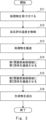
次に、図3を参照して、反応装置10が実行する生成物R11の製造方法(生成物製造方法)について説明する。図3は、反応装置10が実行する処理のフローチャートである。図3に示すフローチャートは、例えば反応装置10に対して処理物R10の供給を開始することにより開始する。 Next, a method for producing the product R11 (product production method) performed by the reaction device 10 will be described with reference to FIG. 3. FIG. 3 is a flowchart of the process performed by the reaction device 10. The flowchart shown in FIG. 3 starts, for example, by starting the supply of the product R10 to be treated to the reaction device 10.

まず、反応装置10は、供給口101から所定の処理物R10を受け付ける(ステップS11)。 First, the reaction device 10 receives a predetermined treatment material R10 from the supply port 101 (step S11).

次に、反応装置10の制御装置200は、温度制御部202を介して、反応容器100の温度制御領域110の加熱装置または冷却装置を駆動することにより温度を制御する(ステップS12)。 Next, the control device 200 of the reaction device 10 controls the temperature by driving the heating device or cooling device in the temperature control region 110 of the reaction vessel 100 via the temperature control unit 202 (step S12).

次に、反応装置10の制御装置200は、搬送制御部203を介して駆動装置150を駆動する。これにより駆動装置150は搬送機構120を駆動させる。そして搬送機構120は、受け入れた処理物R10を送出口102に向かって搬送する(ステップS13)。 Next, the control device 200 of the reaction device 10 drives the drive device 150 via the transport control unit 203. This causes the drive device 150 to drive the transport mechanism 120. The transport mechanism 120 then transports the received processed material R10 toward the discharge port 102 (step S13).

次に、反応装置10の制御装置200は、第1流体制御部204を介して、第1流体制御領域130(第1雰囲気制御領域)に通過させる第1流体の流れを制御する(ステップS14)。 Next, the control device 200 of the reaction device 10 controls the flow of the first fluid to be passed through the first fluid control region 130 (first atmosphere control region) via the first fluid control unit 204 (step S14).

次に、反応装置10の制御装置200は、第2流体制御部205を介して、第2流体制御領域140(第2雰囲気制御領域)に通過させる第2流体の流れを制御する(ステップS15)。 Next, the control device 200 of the reaction device 10 controls the flow of the second fluid to be passed through the second fluid control region 140 (second atmosphere control region) via the second fluid control unit 205 (step S15).

次に、反応装置10は、第2流体制御領域140を通過した生成物R11を送出口102から送出する(ステップS16)。 Next, the reaction device 10 discharges the product R11 that has passed through the second fluid control region 140 from the discharge outlet 102 (step S16).

以上、反応装置10が実行する反応方法(生成物製造方法)について説明した。上述の方法は、反応装置10が処理物R10から生成物R11を製造し、製造した生成物R11を排出するまでの流れに沿って示されている。しかし、反応装置10は、例えばステップS12における温度制御を、ステップS11の前から実行していてもよい。また例えば反応装置10は、ステップS14とステップS15とを同時に開始してもよい。 The above describes the reaction method (product production method) executed by the reaction device 10. The above-mentioned method is shown along the flow from when the reaction device 10 produces the product R11 from the treated material R10 to when the produced product R11 is discharged. However, the reaction device 10 may, for example, perform the temperature control in step S12 before step S11. Also, for example, the reaction device 10 may start steps S14 and S15 simultaneously.

以上、参考例1について説明した。なお、上述の反応装置10において、反応装置10は2つの流体制御領域(第1流体制御領域130および第2流体制御領域140)を有しているが、反応装置10は1つもしくは3つ以上の流体制御領域を有してもよい。また反応装置10は、搬送機構120の軸AX120方向(長軸方向)に沿って複数の温度制御領域110を有していてもよい。上述の反応装置10は、供給口101から受け入れた処理物R10に対して、中間部A3において複数の流体を別個に接触させる。また反応装置10は、中間部A3において、搬送機構120の軸AX120方向(長軸方向)に沿って、反応容器100の温度制御を行う。さらに反応装置10は、反応容器100の内部の物体を搬送し、物理的な刺激を与えることができる。反応装置10は上述の雰囲気制御、温度制御および物理制御を、同時に、且つ、精度よく行うことができる。よって、参考例1によれば、所望の製品を効率よく製造する反応装置等を提供することができる。 Reference Example 1 has been described above. In the above-mentioned reaction apparatus 10, the reaction apparatus 10 has two fluid control regions (the first fluid control region 130 and the second fluid control region 140), but the reaction apparatus 10 may have one or three or more fluid control regions. The reaction apparatus 10 may have a plurality of temperature control regions 110 along the axis AX 120 direction (long axis direction) of the transport mechanism 120. The above-mentioned reaction apparatus 10 separately contacts a plurality of fluids with the processing object R10 received from the supply port 101 in the intermediate section A3. The reaction apparatus 10 also performs temperature control of the reaction vessel 100 along the axis AX 120 direction (long axis direction) of the transport mechanism 120 in the intermediate section A3. Furthermore, the reaction apparatus 10 can transport an object inside the reaction vessel 100 and provide a physical stimulus. The reaction apparatus 10 can simultaneously and accurately perform the above-mentioned atmosphere control, temperature control, and physical control. Therefore, according to the first embodiment, a reaction apparatus or the like that efficiently produces a desired product can be provided.

<参考例2>
次に、参考例2として、図4を参照しながら、反応容器100を支持する構成例、搬送機構120を支持する構成例について説明する。この構成例は、上記参考例2に適用することができる。図4は、参考例2にかかる反応装置の側面図である。図4は、図1に対して第1支持部103、第2支持部104を追加したものに相当する。それ以外は、図1と同様の構成である。以下、参考例1との相違点を中心に説明する。
<Reference Example 2>
Next, as Reference Example 2, a configuration example for supporting the reaction vessel 100 and a configuration example for supporting the transport mechanism 120 will be described with reference to Fig. 4. This configuration example can be applied to the above-mentioned Reference Example 2. Fig. 4 is a side view of a reaction apparatus according to Reference Example 2. Fig. 4 corresponds to Fig. 1 to which a first support part 103 and a second support part 104 have been added. Other than that, the configuration is the same as Fig. 1. Below, the differences from Reference Example 1 will be mainly described.

<反応容器100を支持する構成例>
図4に示すように、反応装置10は、反応容器100を支持する構成として、第1支持部103、第2支持部104を備えている。図4の反応容器100は、一端側A1と他端側A2との間の中間部A3を含む筒状の反応容器(炉)であって、床面170に設置された第1支持部103及び第2支持部104により支持されている。なお、床面170とは、反応装置10が設置される建屋の床面としてもよいし、例えば架台の上面のように反応装置10を構成する構造の一部の面としてもよい。
<Example of a configuration for supporting the reaction vessel 100>
As shown in Fig. 4, the reaction apparatus 10 includes a first support part 103 and a second support part 104 as a structure for supporting the reaction vessel 100. The reaction vessel 100 in Fig. 4 is a cylindrical reaction vessel (furnace) including an intermediate part A3 between one end side A1 and the other end side A2, and is supported by the first support part 103 and the second support part 104 installed on a floor surface 170. The floor surface 170 may be the floor surface of a building in which the reaction apparatus 10 is installed, or may be a surface of a part of a structure constituting the reaction apparatus 10, such as the upper surface of a stand.

第1支持部103は、反応容器100の一端側A1の下方の床面170に配置されており、当該反応容器100の一端側A1を下方から支持する。具体的には、第1支持部103は、反応容器100の一端側A1を、反応容器100の長軸AX100方向に移動不能な状態で支持する。これは、例えば、第1支持部103に支持された反応容器100の一端側A1を、ボルトや溶接等の直接的な固定手段により第1支持部103に固定することにより実現される。あるいは、直接的な固定手段に限らず、例えば、第1支持部103に支持された反応容器100の一端側A1に対して、架台等に別途固定された板材や線材等の部材を接触させ、間接的に固定することで実現してもよい。 The first support part 103 is disposed on a floor surface 170 below one end side A1 of the reaction vessel 100, and supports one end side A1 of the reaction vessel 100 from below. Specifically, the first support part 103 supports one end side A1 of the reaction vessel 100 in a state in which it cannot move in the direction of the long axis AX100 of the reaction vessel 100. This is realized, for example, by fixing one end side A1 of the reaction vessel 100 supported by the first support part 103 to the first support part 103 by a direct fixing means such as a bolt or welding. Alternatively, it is not limited to a direct fixing means, and may be realized, for example, by contacting a member such as a plate material or a wire material separately fixed to a stand or the like with the one end side A1 of the reaction vessel 100 supported by the first support part 103 and indirectly fixing it.

一方、第2支持部104は、反応容器100の他端側A2の下方の床面170に配置されており、当該反応容器100の他端側A2を下方から支持する。具体的には、第2支持部104は、反応容器100の他端側A2を、反応容器100の長軸AX100方向に移動可能な状態で支持する。これは、例えば、後述する具体例1~3により実現される。 On the other hand, the second support part 104 is disposed on a floor surface 170 below the other end side A2 of the reaction vessel 100, and supports the other end side A2 of the reaction vessel 100 from below. Specifically, the second support part 104 supports the other end side A2 of the reaction vessel 100 in a state in which the other end side A2 of the reaction vessel 100 can move in the direction of the long axis AX100 of the reaction vessel 100. This is realized, for example, by specific examples 1 to 3 described later.

反応容器100の他端側A2を、反応容器100の長軸AX100方向に移動可能な状態で支持する技術的意義は次のとおりである。 The technical significance of supporting the other end side A2 of the reaction vessel 100 in a state in which it can move in the direction of the major axis AX100 of the reaction vessel 100 is as follows.

すなわち、上記参考例1で説明したように温度制御装置210等により反応容器100の温度を制御すると(例えば、常温から900度程度に加熱すると)、反応容器100がその長軸AX100方向に熱膨張する(例えば、長軸AX100方向に10~20mm程度熱膨張する)。その際、仮に、反応容器100の他端側A2がその長軸AX100方向に移動不能であると、反応容器100が長軸AX100方向に熱膨張することにより駆動装置150に力が作用し、当該駆動装置150が破損する恐れがある。例えば、駆動装置150(例えば、減速機)を構成するギヤ(1又は複数)の回転軸が変形し、当該駆動装置150(例えば、減速機)が正常に動作できなくなる恐れがある。あるいは、搬送機構120が大きく変形し、正常に搬送できなくなる恐れがある。 That is, when the temperature of the reaction vessel 100 is controlled by the temperature control device 210 or the like as described in the above-mentioned Reference Example 1 (for example, when heated from room temperature to about 900 degrees), the reaction vessel 100 thermally expands in the direction of its long axis AX100 (for example, thermally expands about 10 to 20 mm in the direction of the long axis AX100 ). At that time, if the other end side A2 of the reaction vessel 100 cannot move in the direction of its long axis AX100 , the reaction vessel 100 thermally expands in the direction of the long axis AX100 , and a force acts on the driving device 150, which may damage the driving device 150. For example, the rotating shaft of the gear (one or more) constituting the driving device 150 (for example, a reducer) may be deformed, and the driving device 150 (for example, a reducer) may not be able to operate normally. Or, the transport mechanism 120 may be significantly deformed, making it impossible to transport normally.

そこで、反応容器100が長軸AX100方向に熱膨張することにより駆動装置150に力が作用し、当該駆動装置150が破損するの等を防止するため、第2支持部104により、反応容器100の他端側A2を、反応容器100の長軸AX100方向に移動可能な状態で支持する。 Therefore, in order to prevent a force acting on the driving device 150 due to thermal expansion of the reaction vessel 100 in the direction of the major axis AX100, causing damage to the driving device 150, the other end side A2 of the reaction vessel 100 is supported by the second support part 104 in a state in which it can move in the direction of the major axis AX100 of the reaction vessel 100.

次に、反応容器100の他端側A2を、反応容器100の長軸AX100方向に移動可能な状態で支持する具体例について説明する。 Next, a specific example in which the other end side A2 of the reaction vessel 100 is supported in a state in which it can move in the direction of the major axis AX100 of the reaction vessel 100 will be described.

<具体例1>
図5(a)は、反応容器100の他端側A2を、反応容器100の長軸AX100方向に移動可能な状態で支持する具体例1を表す図である。図5(a)は、図4中の矢印AR1方向から見た矢視図である。
<Specific Example 1>
5A is a diagram showing a first specific example in which the other end side A2 of the reaction vessel 100 is supported in a state in which it can move in the direction of the major axis AX100 of the reaction vessel 100. FIG 5A is a view seen from the direction of the arrow AR1 in FIG 4.

図5(a)に示すように、具体例1は、反応容器100の他端側A2を、反応容器100の長軸AX100方向に移動可能とするため、反応容器100の他端側A2にフランジ部109を設け、フランジ部109の下部に凹部109aを形成し、第2支持部104の上部に凹部109aに挿入される凸部104aを設け、凹部109aに凸部104aが挿入された状態で反応容器100の他端側A2を支持した例である。凹部109a及び凸部104aは、反応容器100の長軸AX100方向に延びている。フランジ部109の下面109bと第2支持部104の上面104bとの間には、隙間G1が形成されている。凹部109aと凸部104aの間に潤滑油等を供給してもよい。なお、逆に、フランジ部109の下部に凸部104aを設け、第2支持部104の上部に凸部104aが挿入される凹部109aを形成してもよい。 As shown in FIG. 5A, in the specific example 1, in order to make the other end side A2 of the reaction vessel 100 movable in the direction of the long axis AX100 of the reaction vessel 100, a flange portion 109 is provided on the other end side A2 of the reaction vessel 100, a recess 109a is formed on the lower part of the flange portion 109, a protrusion 104a to be inserted into the recess 109a is provided on the upper part of the second support portion 104, and the other end side A2 of the reaction vessel 100 is supported in a state in which the protrusion 104a is inserted into the recess 109a. The recess 109a and the protrusion 104a extend in the direction of the long axis AX100 of the reaction vessel 100. A gap G1 is formed between the lower surface 109b of the flange portion 109 and the upper surface 104b of the second support portion 104. Lubricating oil or the like may be supplied between the recess 109a and the protrusion 104a. Conversely, the protrusion 104a may be provided on the lower part of the flange portion 109, and the upper part of the second support portion 104 may be formed with a recess 109a into which the protrusion 104a is inserted.

<具体例2>
図5(b)は、反応容器100の他端側A2を、反応容器100の長軸AX100方向に移動可能な状態で支持する具体例2を表す図である。図5(b)は、図4中の矢印AR1方向から見た矢視図である。
<Specific example 2>
5B is a diagram showing a second specific example in which the other end A2 of the reaction vessel 100 is supported in a state in which it can move in the direction of the major axis AX100 of the reaction vessel 100. FIG. 5B is a view seen from the direction of the arrow AR1 in FIG.

図5(b)に示すように、具体例2は、反応容器100の他端側A2を、反応容器100の長軸AX100方向に移動可能とするため、反応容器100の他端側A2にフランジ部109を設け、第2支持部104の上面104bに摩擦低減部材111を設け、フランジ部109の下面109bが摩擦低減部材111に接した状態で反応容器100の他端側A2を支持した例である。摩擦低減部材111は反応容器100を滑らかに移動させる部材であれば形態、形状、素材は特に限定されない。摩擦低減部材111は例えばローラやベルト等の回転部を有する部材であっても良い。摩擦低減部材111は例えば焼き入れ熱処理が可能な工具鋼材や窒化熱処理が可能な窒化鋼材、少なくとも一部にセラミック粒子を含有する粉末冶金材、またはコーティングが表面に施された鋼材のように、摩擦低減部材111が反応容器100を支持する面のビッカース硬さ(HV)が450以上もしくはロックウェル硬さ(HRC)が45以上の高硬度材から成る部材であっても良い。摩擦低減部材111は例えばタイヤモンドライクカーボン(DLC)、炭化チタン(TiC)、炭窒化チタン(TiBN)、ホウ化チタン(TiB)、炭化バナジウム(VC)、アルミナ(Al)やジルコニア(ZrO)等がCVD、PVD、溶射等の成膜手段により表面にコーティングされた部材であっても良い。摩擦低減部材111はクロムめっきやニッケルめっき(Ni-PやNi-Co-W)が電気めっきや無電解めっきにより表面にコーティングされた部材であっても良い。摩擦低減部材111は二硫化モリブデンのように固体潤滑性を有する化合物がスプレー等の塗布手段により表面にコーティングされた部材であっても良い。すなわち、摩擦低減部材111が反応容器100を支持する面(支持面)の化学組成には、B、C、N、Al、P、Ti、V、Cr、Co、Ni、Mo、Wの元素(化学元素)のうち少なくとも1つが含まれていることが好ましい。 5B, in the specific example 2, in order to make the other end side A2 of the reaction vessel 100 movable in the direction of the long axis AX100 of the reaction vessel 100, a flange portion 109 is provided on the other end side A2 of the reaction vessel 100, a friction reduction member 111 is provided on the upper surface 104b of the second support portion 104, and the other end side A2 of the reaction vessel 100 is supported with the lower surface 109b of the flange portion 109 in contact with the friction reduction member 111. The form, shape, and material of the friction reduction member 111 are not particularly limited as long as it is a member that smoothly moves the reaction vessel 100. The friction reduction member 111 may be a member having a rotating part such as a roller or a belt. The friction reducing member 111 may be a member made of a high hardness material having a Vickers hardness (HV) of 450 or more or a Rockwell hardness (HRC) of 45 or more on the surface supporting the reaction vessel 100, such as a tool steel material that can be subjected to a quenching heat treatment, a nitrided steel material that can be subjected to a nitriding heat treatment, a powder metallurgy material that contains ceramic particles at least in a part, or a steel material with a coating applied to the surface. The friction reducing member 111 may be a member whose surface is coated with, for example, diamond-like carbon (DLC), titanium carbide (TiC), titanium carbonitride (TiBN), titanium boride (TiB 2 ), vanadium carbide (VC), alumina (Al 2 O 3 ), zirconia (ZrO 2 ), or the like by a film forming means such as CVD, PVD, or thermal spraying. The friction reducing member 111 may be a member whose surface is coated with chrome plating or nickel plating (Ni-P or Ni-Co-W) by electroplating or electroless plating. The friction reducing member 111 may be a member whose surface is coated with a compound having solid lubricating properties, such as molybdenum disulfide, by a coating means such as a spray. In other words, the chemical composition of the surface (support surface) of the friction reducing member 111 that supports the reaction vessel 100 preferably contains at least one of the elements (chemical elements) B, C, N, Al, P, Ti, V, Cr, Co, Ni, Mo, and W.

<具体例3>
図5(c)は、反応容器100の他端側A2を、反応容器100の長軸AX100方向に移動可能な状態で支持する具体例3を表す図である。図5(c)は、図4中の矢印AR1方向から見た矢視図である。
<Specific example 3>
5(c) is a diagram showing a specific example 3 in which the other end side A2 of the reaction vessel 100 is supported in a state in which it can move in the direction of the major axis AX100 of the reaction vessel 100. FIG 5(c) is a view seen from the direction of the arrow AR1 in FIG 4.

図5(c)に示すように、具体例3は、反応容器100の他端側A2を、反応容器100の長軸AX100方向に移動可能とするため、反応容器100の他端側A2に左右両側に突出する(反応容器100の長軸に交差(例えば直交)する向きに突出する)突出部109c、109dを有するフランジ部109を設け、第2支持部104の上面104bに起立部104c、104dを設け、突出部109c、109dを起立部104c、104dに載せた状態で反応容器100の他端側A2を支持した例である。フランジ部109の下面109bと第2支持部104の上面104bとの間には隙間G2が形成され、かつ、フランジ部109の左右両側と起立部104c、104dとの間には隙間G3、G4が形成されている。突出部109c、109dと起立部104c、104dの間に潤滑油等を供給してもよい。 5(c), in the specific example 3, in order to make the other end side A2 of the reaction vessel 100 movable in the direction of the long axis AX100 of the reaction vessel 100, a flange portion 109 having protruding portions 109c, 109d protruding on both the left and right sides (protruding in a direction intersecting (for example, perpendicular to) the long axis of the reaction vessel 100) is provided on the other end side A2 of the reaction vessel 100, standing portions 104c, 104d are provided on the upper surface 104b of the second support portion 104, and the other end side A2 of the reaction vessel 100 is supported in a state in which the protruding portions 109c, 109d are placed on the standing portions 104c, 104d. A gap G2 is formed between the lower surface 109b of the flange portion 109 and the upper surface 104b of the second support portion 104, and gaps G3, G4 are formed between the left and right sides of the flange portion 109 and the standing portions 104c, 104d. Lubricating oil or the like may be supplied between the protruding portions 109c, 109d and the upright portions 104c, 104d.

上記具体例1~3のように、反応容器100の他端側A2を反応容器100の長軸AX100方向に移動可能な状態で支持することにより、反応容器100がその長軸AX100方向に熱膨張(又は熱収縮)することに起因して駆動装置150に力が作用し、当該駆動装置150が破損等するのを防止することができる。 As in the above-mentioned specific examples 1 to 3, by supporting the other end side A2 of the reaction vessel 100 in a state in which it can move in the direction of the long axis AX100 of the reaction vessel 100, it is possible to prevent the driving device 150 from being damaged or the like due to a force acting on the driving device 150 caused by the thermal expansion (or thermal contraction) of the reaction vessel 100 in the direction of the long axis AX100.

<搬送機構120を支持する構成例>
図4に示すように、反応装置10は、搬送機構120としてのスクリュを支持する構成として、軸受け106、107を備えている。
<Example of configuration for supporting the transport mechanism 120>
As shown in FIG. 4, the reaction apparatus 10 includes bearings 106 and 107 as a structure for supporting the screw serving as the transport mechanism 120 .

軸受け106は、反応容器100の一端側A1に設けられており、搬送機構120の一端側B1を回転可能な状態で支持する。軸受け106は、例えば、ベアリング、ブッシュである。搬送機構120の一端側B1は、減速機152の出力軸に連結(固定)されている。すなわち、搬送機構120の一端側B1は、回転可能、かつ、搬送機構120の軸AX120方向に移動不能な状態で支持されている。 The bearing 106 is provided at one end side A1 of the reaction vessel 100, and rotatably supports one end side B1 of the transport mechanism 120. The bearing 106 is, for example, a bearing or a bush. The one end side B1 of the transport mechanism 120 is connected (fixed) to the output shaft of the reducer 152. That is, the one end side B1 of the transport mechanism 120 is supported in a state in which it can rotate and cannot move in the direction of the axis AX120 of the transport mechanism 120.

一方、軸受け107は、反応容器100の他端側A2に設けられており、搬送機構120の他端側B2を回転可能、かつ、搬送機構120の軸AX120方向に移動可能な状態で支持する。軸受け107が本開示の第3支持部、第6支持部の一例である。軸受け107は、例えば、ベアリング、ブッシュである。なお、搬送機構120の他端側B2を、搬送機構120の軸AX120方向に移動可能とするため、搬送機構120の他端側B2の所定範囲(図4中、符号L1が示す範囲参照)には、螺旋状の凸部121が設けられていない。また、搬送機構120の他端側B2の端部と反応容器100の他端側A2に設けられた蓋部108との間には、搬送機構120の軸AX120方向(図4中右側)に移動する搬送機構120の他端側B2が進入するスペース(図4中、符号L2が示す範囲参照)が設けられている。 On the other hand, the bearing 107 is provided on the other end side A2 of the reaction vessel 100, and supports the other end side B2 of the transport mechanism 120 in a state in which the other end side B2 can rotate and move in the axis AX120 direction of the transport mechanism 120. The bearing 107 is an example of a third support part and a sixth support part of the present disclosure. The bearing 107 is, for example, a bearing or a bush. Note that, in order to allow the other end side B2 of the transport mechanism 120 to move in the axis AX120 direction of the transport mechanism 120, a spiral convex part 121 is not provided in a predetermined range of the other end side B2 of the transport mechanism 120 (see the range indicated by the symbol L1 in FIG. 4). In addition, between the end of the other end side B2 of the transport mechanism 120 and the lid portion 108 provided on the other end side A2 of the reaction vessel 100, a space (see the range indicated by the symbol L2 in FIG. 4) is provided for the entry of the other end side B2 of the transport mechanism 120 moving in the direction of the axis AX120 of the transport mechanism 120 (right side in FIG. 4).

以上のように支持された搬送機構120の軸AX120と反応容器100の長軸AX100は一致(略一致)している。 The axis AX 120 of the transport mechanism 120 supported as described above and the major axis AX 100 of the reaction vessel 100 coincide (substantially coincide).

搬送機構120の他端側B2を、搬送機構120の軸AX120方向に移動可能な状態で支持する技術的意義は次のとおりである。 The technical significance of supporting the other end side B2 of the transport mechanism 120 in a state in which it can move in the direction of the axis AX120 of the transport mechanism 120 is as follows.

すなわち、上記参考例1で説明したように温度制御装置210等により反応容器100の温度を制御すると(例えば、常温から摂氏900度程度に加熱すると)、反応容器100がその長軸AX100方向に熱膨張する(例えば、長軸AX100方向に10~20mm程度熱膨張する)。これと共に、搬送機構120もその軸AX120方向に熱膨張する(例えば、軸AX120方向に10~20mm程度熱膨張する)。その際、仮に、搬送機構120の他端側B2がその軸AX120方向に移動不能であると、搬送機構120が軸AX120方向に熱膨張することにより搬送機構120が変形し、この変形した搬送機構120の螺旋状の凸部121等が反応容器100の内壁に接触し、搬送機構120が正常に回転できなくなる等の恐れがある。 That is, when the temperature of the reaction vessel 100 is controlled by the temperature control device 210 or the like as described in the above-mentioned Reference Example 1 (for example, when heated from room temperature to about 900 degrees Celsius), the reaction vessel 100 thermally expands in the direction of its long axis AX100 (for example, thermally expands about 10 to 20 mm in the direction of the long axis AX100 ). At the same time, the transport mechanism 120 also thermally expands in the direction of its axis AX120 (for example, thermally expands about 10 to 20 mm in the direction of the axis AX120 ). At that time, if the other end side B2 of the transport mechanism 120 cannot move in the direction of the axis AX120 , the transport mechanism 120 is deformed by the thermal expansion in the direction of the axis AX120, and the spiral convex portion 121 of the deformed transport mechanism 120 may come into contact with the inner wall of the reaction vessel 100, and the transport mechanism 120 may not be able to rotate normally.

また、搬送機構120の一端側B1を搬送機構120の軸AX120方向に移動可能な状態とし、搬送機構120の他端側B2を搬送機構120の軸AX120方向に移動不能な状態とした場合、反応容器100の熱膨張や熱収縮に伴って搬送機構120の他端側B2が移動するため、スクリュの凸部および凹部の位置の制御が困難となり、処理物を正常に反応できなくなる等の恐れがある。 Furthermore, if one end B1 of the transport mechanism 120 is made movable in the direction of the axis AX120 of the transport mechanism 120 and the other end B2 of the transport mechanism 120 is made immovable in the direction of the axis AX120 of the transport mechanism 120, the other end B2 of the transport mechanism 120 moves in accordance with the thermal expansion or contraction of the reaction vessel 100, making it difficult to control the positions of the convex and concave parts of the screw, and there is a risk that the material to be processed will not react normally.

そこで、搬送機構120が軸AX120方向に熱膨張することにより搬送機構120が変形するのを防止するため、軸受け107により、搬送機構120の他端側B2を、回転可能、かつ、搬送機構120の軸AX120方向に移動可能な状態で支持する。 Therefore, in order to prevent the transport mechanism 120 from being deformed due to thermal expansion of the transport mechanism 120 in the direction of the axis AX120, the other end side B2 of the transport mechanism 120 is supported by a bearing 107 in a state in which the other end side B2 of the transport mechanism 120 is rotatable and movable in the direction of the axis AX120 of the transport mechanism 120.

以上のように、搬送機構120の他端側B2を回転可能、かつ、搬送機構120の軸AX120方向に移動可能な状態で支持することにより、搬送機構120がその軸AX120方向に熱膨張することに起因して搬送機構120が変形するのを防止することができる。 As described above, by supporting the other end B2 of the transport mechanism 120 in a state in which it can rotate and move in the direction of the axis AX120 of the transport mechanism 120, it is possible to prevent the transport mechanism 120 from being deformed due to thermal expansion of the transport mechanism 120 in the direction of the axis AX120 .

以上説明したように、参考例2によれば、反応容器100がその長軸AX100方向に熱膨張しても、これに起因して正常に動作できなくなるのを防止することができる反応装置10を提供することができる。 As described above, according to Reference Example 2, even if the reaction vessel 100 thermally expands in the direction of the major axis AX100 , the reaction device 10 can be provided, which can prevent the reaction vessel 100 from being unable to operate normally due to the thermal expansion.

次に、変形例について説明する。 Next, we will explain the modified example.

上記参考例2では、回転不能に支持された反応容器100を用いた例について説明したが、これに限らない。例えば、回転可能に支持された反応容器100を用いてもよい。 In the above-mentioned Reference Example 2, an example was described in which a reaction vessel 100 supported in a non-rotatable manner was used, but this is not limited thereto. For example, a reaction vessel 100 supported in a rotatable manner may also be used.

図6は、反応容器100を回転可能に支持する構成例である。 Figure 6 shows an example of a configuration for supporting the reaction vessel 100 in a rotatable manner.

図6に示すように、本変形例の反応装置10は、反応容器100を回転可能に支持する構成として、軸受け112、113を備えている。 As shown in FIG. 6, the reaction device 10 of this modified example is equipped with bearings 112 and 113 to rotatably support the reaction vessel 100.

軸受け112は、反応容器100の一端側A1と第1支持部103の間に設けられており、反応容器100の一端側A1を回転可能、かつ、反応容器100の長軸AX100方向に移動不能な状態で支持する。軸受け112は、例えば、ベアリング、ブッシュである。反応容器100の一端側A1には、フランジ部114が設けられている。このフランジ部114が軸受け112に接触することにより、反応容器100の一端側A1が反応容器100の長軸AX100方向(図6中右側)に移動するのが防止される。フランジ部114および軸受け112は複数設けてもよい。例えば、1つのフランジ部114に対して2つの軸受け112を用い、フランジ部114を軸受け112で挟むようにすることで反応容器100の一端側A1が反応容器100の長軸AX100方向に移動するのがより好適に防止される。なお、軸受け112は、反応容器100の一端側A1が挿入される輪状のベアリング又はブッシュであってもよいし、輪状のベアリング又はブッシュの一部を切り欠いた円弧状のベアリング又はブッシュであってもよい。なお、軸受け112に代えて、潤滑性のある材料により構成される部材により、反応容器100の一端側A1を回転可能、かつ、反応容器100の長軸AX100方向に移動不能な状態で支持してもよい。軸受け112及びフランジ部114が本開示の第4支持部の一例である。 The bearing 112 is provided between the one end side A1 of the reaction vessel 100 and the first support part 103, and supports the one end side A1 of the reaction vessel 100 in a rotatable state and in a state where it cannot move in the long axis AX100 direction of the reaction vessel 100. The bearing 112 is, for example, a bearing or a bush. The one end side A1 of the reaction vessel 100 is provided with a flange part 114. The flange part 114 comes into contact with the bearing 112, thereby preventing the one end side A1 of the reaction vessel 100 from moving in the long axis AX100 direction of the reaction vessel 100 (right side in FIG. 6). A plurality of flange parts 114 and bearings 112 may be provided. For example, two bearings 112 are used for one flange part 114, and the flange part 114 is sandwiched between the bearings 112, so that the one end side A1 of the reaction vessel 100 is more suitably prevented from moving in the long axis AX100 direction of the reaction vessel 100 . The bearing 112 may be an annular bearing or bushing into which the one end side A1 of the reaction vessel 100 is inserted, or may be an arc-shaped bearing or bushing obtained by cutting out a part of the annular bearing or bushing. Instead of the bearing 112, a member made of a lubricating material may support the one end side A1 of the reaction vessel 100 in a rotatable state but immovable in the direction of the long axis AX100 of the reaction vessel 100. The bearing 112 and the flange portion 114 are an example of a fourth support portion of the present disclosure.

一方、軸受け113は、反応容器100の他端側A2と第2支持部104の間に設けられており、反応容器100の他端側A2を回転可能、かつ、反応容器100の長軸AX100方向に移動可能な状態で支持する。軸受け113は、例えば、ベアリング、ブッシュである。なお、軸受け113は、反応容器100の他端側A2が挿入される輪状のベアリング又はブッシュであってもよいし、輪状のベアリング又はブッシュの一部を切り欠いた円弧状のベアリング又はブッシュであってもよい。なお、軸受け113に代えて、潤滑性のある材料により構成される部材により、反応容器100の他端側A2を回転可能、かつ、反応容器100の長軸AX100方向に移動可能な状態で支持してもよい。軸受け113が本開示の第5支持部の一例である。本変形例の回転可能に支持された反応容器100は、一端側A1において駆動装置150(スクリュ駆動装置)と同様の反応容器駆動装置116(図6中省略)に接続(連結)している。 On the other hand, the bearing 113 is provided between the other end side A2 of the reaction vessel 100 and the second support part 104, and supports the other end side A2 of the reaction vessel 100 in a state in which it can rotate and move in the long axis AX100 direction of the reaction vessel 100. The bearing 113 is, for example, a bearing or a bush. The bearing 113 may be a ring-shaped bearing or bush into which the other end side A2 of the reaction vessel 100 is inserted, or may be an arc-shaped bearing or bush in which a part of the ring-shaped bearing or bush is cut out. Instead of the bearing 113, a member made of a lubricating material may support the other end side A2 of the reaction vessel 100 in a state in which it can rotate and move in the long axis AX100 direction of the reaction vessel 100. The bearing 113 is an example of a fifth support part of the present disclosure. The rotatably supported reaction vessel 100 of this modified example is connected (coupled) at one end side A1 to a reaction vessel drive device 116 (not shown in FIG. 6) similar to the drive device 150 (screw drive device).

本変形例のように、反応容器100を回転可能に支持する構成を用いる場合、回転可能に支持された搬送機構120(図4参照)を用いてもよいし、回転可能に支持された搬送機構120に代えて、回転不能に支持された搬送機構120(図示せず)を用いてもよい。また、搬送機構120を省略してもよい。 When using a configuration in which the reaction vessel 100 is rotatably supported as in this modified example, a rotatably supported transport mechanism 120 (see FIG. 4) may be used, or a non-rotatably supported transport mechanism 120 (not shown) may be used instead of the rotatably supported transport mechanism 120. Also, the transport mechanism 120 may be omitted.

また、上記参考例2では、第1支持部として、反応容器100の一端側A1を下方から支持する第1支持部103を用いた例について説明したが、これに限らない。すなわち、第1支持部は、反応容器100の一端側A1をその長軸AX100方向に移動不能な状態で支持する支持部であればどのような構成であってもよい。例えば、図示しないが、第1支持部として、反応容器100の一端側A1を上方から吊り下げる形態で支持する第1支持部を用いてもよいし、反応容器100の一端側A1を側方から支持する第1支持部を用いてもよい。 In addition, in the above-mentioned Reference Example 2, an example was described in which the first support part 103 that supports the one end side A1 of the reaction vessel 100 from below was used as the first support part, but the present invention is not limited to this. That is, the first support part may have any configuration as long as it supports the one end side A1 of the reaction vessel 100 in a state in which it cannot move in the direction of the long axis AX100 . For example, although not shown, the first support part may be a first support part that supports the one end side A1 of the reaction vessel 100 in a form of suspending it from above, or a first support part that supports the one end side A1 of the reaction vessel 100 from the side.

また、上記参考例2では、第2支持部104として、反応容器100の他端側A2を下方から支持する支持部を用いた例について説明したが、これに限らない。すなわち、第2支持部は、反応容器100の他端側A2をその長軸AX100方向に移動可能な状態で支持する支持部であればどのような構成であってもよい。例えば、図示しないが、第2支持部として、反応容器100の他端側A2を上方から吊り下げる形態で支持する第2支持部を用いてもよいし、反応容器100の他端側A2を側方から支持する第2支持部を用いてもよい。 In the above-mentioned Reference Example 2, an example was described in which a support part that supports the other end side A2 of the reaction vessel 100 from below was used as the second support part 104 , but the present invention is not limited thereto. That is, the second support part may have any configuration as long as it supports the other end side A2 of the reaction vessel 100 in a state in which the other end side A2 can be moved in the direction of the long axis AX100. For example, although not shown, a second support part that supports the other end side A2 of the reaction vessel 100 in a suspended form from above may be used as the second support part, or a second support part that supports the other end side A2 of the reaction vessel 100 from the side may be used.

上記参考例では、図5(a)、図7に示すように、第2支持部104が、反応容器100の他端側A2を、反応容器100の長軸AX100方向にのみ移動可能な状態で支持する例について説明したが、これに限らない。図7は、図5(a)中の矢印AR2方向から見た矢視図である。例えば、反応容器100の他端側A2を、反応容器100の長軸AX100方向に加え、回転軸AX(鉛直軸)を中心に回転可能な状態で支持してもよい。 In the above-mentioned reference example, as shown in Fig. 5(a) and Fig. 7, an example has been described in which the second support part 104 supports the other end side A2 of the reaction vessel 100 in a state in which the other end side A2 can move only in the direction of the long axis AX100 of the reaction vessel 100 , but the present invention is not limited to this. Fig. 7 is a view seen from the direction of the arrow AR2 in Fig. 5(a). For example, the other end side A2 of the reaction vessel 100 may be supported in a state in which the other end side A2 can rotate around the rotation axis AXV (vertical axis) in addition to the direction of the long axis AX100 of the reaction vessel 100 .

次に、反応容器100の他端側A2を、反応容器100の長軸AX100方向に加え、回転軸AX(鉛直軸)を中心に回転可能な状態で支持する具体例4について説明する。 Next, a fourth specific example will be described in which the other end A2 of the reaction vessel 100 is supported in a state in which it can rotate about a rotation axis AXV (vertical axis) in addition to the direction of the long axis AX100 of the reaction vessel 100.

<具体例4>
図8は、反応容器100の他端側A2を、反応容器100の長軸AX100方向に加え、回転軸AX(鉛直軸)を中心に回転可能な状態で支持する具体例4の概略図である。
<Specific example 4>
FIG. 8 is a schematic diagram of a fourth embodiment in which the other end A2 of the reaction vessel 100 is supported in a rotatable state about a rotation axis AXv (vertical axis) in addition to the direction of the long axis AX100 of the reaction vessel 100. In FIG.

図8に示すように、凸部104aは、ベアリング等を介して回転軸AX(鉛直軸)を中心に回転可能に第2支持部104(上面104b)に支持された台座104e上に設けられている。なお、回転軸AXは、図8中、紙面に直交する方向に延びている。これにより、反応容器100の他端側A2は、反応容器100の長軸AX100方向に加え、回転軸AX(鉛直軸)を中心に回転可能な状態で支持されている。 As shown in Fig. 8, the protruding portion 104a is provided on a base 104e supported by the second support portion 104 (upper surface 104b) so as to be rotatable around a rotation axis AXV (vertical axis) via a bearing or the like. The rotation axis AXV extends in a direction perpendicular to the paper surface in Fig. 8. As a result, the other end side A2 of the reaction vessel 100 is supported in a state in which it can rotate around the rotation axis AXV (vertical axis) in addition to the direction of the long axis AX100 of the reaction vessel 100 .

このように、反応容器100の他端側A2を、反応容器100の長軸AX100方向に加え、回転軸AX(鉛直軸)を中心に回転可能な状態で支持することの利点は次のとおりである。 Thus, the advantage of supporting the other end A2 of the reaction vessel 100 in a state in which it can rotate about the rotation axis AXV (vertical axis) in addition to the direction of the major axis AX100 of the reaction vessel 100 is as follows.

すなわち、反応の状態(物理的な刺激の状態)によっては、図7中、反応容器100の長軸AX100に対して左右で温度差が生じることがある(又はあえて温度差を生じさせることがある)。この場合、反応容器100の長軸AX100に対して左右で伸びる量が異なるという現象が起こる。 That is, depending on the state of the reaction (state of the physical stimulus), a temperature difference may occur between the left and right sides of the long axis AX 100 of the reaction vessel 100 in Fig. 7 (or a temperature difference may be intentionally generated). In this case, a phenomenon occurs in which the amount of extension of the left and right sides of the long axis AX 100 of the reaction vessel 100 differs.

例えば、図7において、反応容器100の長軸AX100に対して右側の温度が高く、左側の温度が低い場合、反応容器100の長軸AX100に対して右側が多く伸び、左側が短く伸びる。図7中の矢印AR3、AR4の長さはこのことを表している。 For example, in Fig. 7, when the temperature is high on the right side of the long axis AX 100 of the reaction vessel 100 and low on the left side, the right side of the long axis AX 100 of the reaction vessel 100 elongates more and the left side elongates less. The lengths of the arrows AR3 and AR4 in Fig. 7 indicate this.

上記のように反応容器100の長軸AX100に対して左右で伸びる量が異なると、反応容器100の他端側A2に水平方向の応力(図7中矢印AR5参照)が発生する場合がある。 If the left and right sides of the reaction vessel 100 are stretched by different amounts with respect to the major axis AX100 as described above, horizontal stress (see arrow AR5 in FIG. 7) may be generated on the other end side A2 of the reaction vessel 100.

この応力が発生した場合、第2支持部104(凸部104a)とフランジ部109(凹部109a)との間に発生する摩擦により、反応容器100(他端側A2)の長軸AX100方向の移動が妨げられるおそれがある。 When this stress occurs, friction occurs between the second support portion 104 (convex portion 104a) and the flange portion 109 (concave portion 109a), which may hinder movement of the reaction vessel 100 (the other end side A2) in the direction of the major axis AX100 .

そこで、図8に示す構成を採用することにより、種々の物理的な刺激の状況に好適に対応することが可能となる。 Therefore, by adopting the configuration shown in Figure 8, it becomes possible to appropriately respond to various physical stimulus situations.

なお、反応容器100の左右で敢えて温度差を生じさせる状態は、特に、二軸型の反応容器100A(図9参照)に適用すると、処理物の反応速度の制御等に有効である。図9は、二軸型の反応容器100Aの例である。 The deliberate creation of a temperature difference between the left and right sides of the reaction vessel 100 is particularly effective for controlling the reaction rate of the material being treated when applied to a twin-axis reaction vessel 100A (see FIG. 9). FIG. 9 shows an example of a twin-axis reaction vessel 100A.

次に、反応容器100の他端側A2を、反応容器100の長軸AX100方向に加え、短軸方向(図10中矢印AR6参照)に移動可能な状態で支持する具体例5について説明する。 Next, a fifth embodiment will be described in which the other end A2 of the reaction vessel 100 is supported so as to be movable in the minor axis direction (see arrow AR6 in FIG. 10) in addition to the major axis direction AX100 of the reaction vessel 100.

<具体例5>
図10は、反応容器100の他端側A2を、反応容器100の長軸AX100方向に加え、短軸方向(図10中矢印AR6参照)に移動可能な状態で支持する具体例5の概略図である。
<Specific Example 5>
FIG. 10 is a schematic diagram of a fifth embodiment in which the other end A2 of the reaction vessel 100 is supported so as to be movable in the minor axis direction (see arrow AR6 in FIG. 10) in addition to the major axis direction AX100 of the reaction vessel 100.

図10に示すように、凸部104aは、ベアリング等を介して回転軸AX(鉛直軸)を中心に回転可能に第2支持部104(上面104b)に支持された台座104e上に設けられている。この台座104eはさらに短軸方向(図10中矢印AR6参照)に移動可能なようにガイドレール104f(第2支持部104(上面104b)に支持されている)に設けられている。なお、回転軸AXは、図10中、紙面に直交する方向に延びている。これにより、反応容器100の他端側A2は、反応容器100の長軸AX100方向に加え、回転軸AX(鉛直軸)を中心に回転可能かつ短軸方向(図10中矢印AR6参照)に移動可能な状態で支持されている。 As shown in Fig. 10, the convex portion 104a is provided on a base 104e supported by the second support portion 104 (upper surface 104b) so as to be rotatable around a rotation axis AXV (vertical axis) via a bearing or the like. The base 104e is further provided on a guide rail 104f (supported by the second support portion 104 (upper surface 104b)) so as to be movable in the minor axis direction (see arrow AR6 in Fig. 10). The rotation axis AXV extends in a direction perpendicular to the paper surface in Fig. 10. As a result, the other end side A2 of the reaction vessel 100 is supported in a state in which it can rotate around the rotation axis AXV (vertical axis) and move in the minor axis direction (see arrow AR6 in Fig. 10) in addition to the major axis AX100 direction of the reaction vessel 100.

このように、反応容器100の他端側A2を、反応容器100の長軸AX100方向に加え、回転軸AX(鉛直軸)を中心に回転可能かつ短軸方向(図10中矢印AR6参照)に移動可能な状態で支持することの利点は次のとおりである。 In this manner, the advantage of supporting the other end side A2 of the reaction vessel 100 in a state in which it can rotate about the rotation axis AXV ( vertical axis) and move in the minor axis direction (see arrow AR6 in FIG. 10 ) in addition to the major axis AX100 direction of the reaction vessel 100 is as follows.

上記応力(図7中矢印AR5参照)が発生した場合、第2支持部104(凸部104a)とフランジ部109(凹部109a)との間に発生する摩擦により、反応容器100(他端側A2)の長軸AX100方向の移動が妨げられるおそれがある。 When the above-mentioned stress (see arrow AR5 in FIG. 7) occurs, the movement of the reaction vessel 100 (the other end side A2) in the direction of the long axis AX100 may be hindered due to friction generated between the second support portion 104 (the convex portion 104a) and the flange portion 109 (the concave portion 109a).

そして、上記変形がさらに大きくなると(上記応力がさらに大きくなると)、反応容器100の他端側A2が傾き(図11(b)参照)、反応容器100が捻れる(図11(a)参照)おそれがある。図11(a)は反応容器100が捻れている状態を表す図、図11(b)は反応容器100が傾いている状態を表す図である。なお、このような捻れや傾きは他端側A2や中間部A3で起こりやすい。 If the above deformation becomes even larger (if the above stress becomes even larger), the other end side A2 of the reaction vessel 100 may tilt (see FIG. 11(b)), and the reaction vessel 100 may twist (see FIG. 11(a)). FIG. 11(a) shows the reaction vessel 100 in a twisted state, and FIG. 11(b) shows the reaction vessel 100 in a tilted state. Such twisting and tilting are likely to occur at the other end side A2 or the middle part A3.

そこで、図10に示す構成を採用することにより、反応容器100の捻れを抑制することが可能となる(図11(c)、図11(d)参照)。図11(c)は反応容器100の捻れが抑制されている状態を表す図、図11(d)は反応容器100の傾きが抑制されている状態を表す図である。 By adopting the configuration shown in Figure 10, it is possible to suppress twisting of the reaction vessel 100 (see Figures 11(c) and 11(d)). Figure 11(c) shows a state in which twisting of the reaction vessel 100 is suppressed, and Figure 11(d) shows a state in which tilting of the reaction vessel 100 is suppressed.

また、上記参考例1、2では、温度制御部(温度制御領域110等)が反応容器100の温度を反応容器100の長軸AX100方向の互いに異なる領域ごとに制御する例について説明したが、これに限らない。すなわち、温度制御部(温度制御領域110等)が温度制御する領域は複数に限らず、1つであってもよい。 In the above-mentioned Reference Examples 1 and 2, the temperature control section (temperature control region 110, etc.) controls the temperature of the reaction vessel 100 for each of different regions in the direction of the long axis AX100 of the reaction vessel 100 , but the present invention is not limited to this. That is, the number of regions to be temperature-controlled by the temperature control section (temperature control region 110, etc.) is not limited to a plurality of regions, and may be one region.

また、上記参考例1、2では、流体供給部(第1流体入口131、第1流体出口132、第1バルブ134等)を用いた例について説明したが、これに限らない。すなわち、流体供給部(第1流体入口131、第1流体出口132、第1バルブ134等)の一部又は全部を省略してもよい。 In addition, in the above Reference Examples 1 and 2, examples using the fluid supply unit (first fluid inlet 131, first fluid outlet 132, first valve 134, etc.) have been described, but this is not limiting. In other words, some or all of the fluid supply unit (first fluid inlet 131, first fluid outlet 132, first valve 134, etc.) may be omitted.

また、上記参考例1、2では、反応容器100の一端側A1に設けられ、搬送機構120(例えばスクリュ)の一端側B1が連結された駆動装置150を用いた例について説明したが、これに限らない。搬送機構120を駆動させる装置として別の駆動装置を用いてもよい。 In addition, in the above-mentioned Reference Examples 1 and 2, an example was described in which a driving device 150 was provided at one end side A1 of the reaction vessel 100 and connected to one end side B1 of the transport mechanism 120 (e.g., a screw), but this is not limited to the above. A different driving device may be used as the device that drives the transport mechanism 120.

<実施形態>
<炉体(温度制御領域110)の具体例>
まず、以下に説明する実施形態の反応装置10の炉体(温度制御領域110)の具体例について説明する。
<Embodiment>
<Specific example of furnace body (temperature control area 110)>
First, a specific example of the furnace body (temperature control region 110) of the reaction apparatus 10 of the embodiment described below will be described.

図12は、炉体(温度制御領域110)の斜視図である。図13は、反応容器100と炉体(温度制御領域110)との関係を表す図である。 Figure 12 is a perspective view of the furnace body (temperature control area 110). Figure 13 is a diagram showing the relationship between the reaction vessel 100 and the furnace body (temperature control area 110).

図12に示すように、炉体(温度制御領域110)は、反応容器100の長軸AX100方向に、合計3つのゾーンD1~D3に分割されている。なお、3つのゾーンに限らず、1、2又は4以上のゾーンに分割されていてもよい。図13に示すように、炉体(温度制御領域110)は、装置架台(床面170)上に配置されたヒータ支持部190により支持されている。一方、反応容器100は、装置架台(床面170)上に配置されたシリンダ支持部(例えば、第1支持部103、第2支持部104)により支持されている。その際、反応容器100は、加熱部Hと反応容器100(全周)との間に空間S0(図17参照)を保った状態で支持されている。 As shown in FIG. 12, the furnace body (temperature control area 110) is divided into a total of three zones D1 to D3 in the direction of the long axis AX 100 of the reaction vessel 100. It is not limited to three zones, and may be divided into one, two, four or more zones. As shown in FIG. 13, the furnace body (temperature control area 110) is supported by a heater support 190 arranged on the device stand (floor surface 170). Meanwhile, the reaction vessel 100 is supported by a cylinder support (for example, a first support 103, a second support 104) arranged on the device stand (floor surface 170). At that time, the reaction vessel 100 is supported in a state where a space S0 (see FIG. 17) is maintained between the heating part H and the reaction vessel 100 (whole circumference).

ゾーンD1は、反応容器100を囲むように反応容器100の長軸AX100周り(周方向)に上下左右の合計4つのゾーンD11~D14に分割されている(図12参照)。なお、4つのゾーンに限らず、1~3又は5以上のゾーンに分割されていてもよい。ゾーンD2、D3も同様である。 Zone D1 is divided into a total of four zones D11 to D14, one above, one below, one to one left, and one to one, around the long axis AX100 of the reaction vessel 100 (circumferential direction) so as to surround the reaction vessel 100 (see FIG. 12). Note that the division is not limited to four zones, and may be into one to three zones or five or more zones. The same applies to zones D2 and D3.

そして、この4つのゾーンD11~D14には、第1加熱部H1、第2加熱部H2、第3加熱部H3、第4加熱部H4が配置されている。このように、加熱部H1~H4は、反応容器100を囲むように反応容器100の長軸AX100周りに配置されている。 In these four zones D11 to D14, a first heating section H1, a second heating section H2, a third heating section H3, and a fourth heating section H4 are arranged. In this manner, the heating sections H1 to H4 are arranged around the major axis AX100 of the reaction vessel 100 so as to surround the reaction vessel 100.

加熱部H1~H4としては、温度制御性を考慮して、電熱線を含むヒータ(電気ヒータ)を用いるのが望ましい。 For the heating sections H1 to H4, it is preferable to use heaters that include heating wires (electric heaters) in consideration of temperature controllability.

図14は、加熱部H1~H4と温度制御部202との電気的な接続関係を表すブロック図である。図14に示すように、各ヒータは、温度制御部202に電気的に接続されている。なお、加熱部H1~H4は、ヒータに限らず、他の加熱手段であってよい。 Figure 14 is a block diagram showing the electrical connection relationship between heating units H1 to H4 and the temperature control unit 202. As shown in Figure 14, each heater is electrically connected to the temperature control unit 202. Note that heating units H1 to H4 are not limited to heaters and may be other heating means.

図示しないが、4つのゾーンD11~D14には、温度計測部が配置されている。温度計測部は、加熱部H1~H4ではなく、反応容器100(例えば、図12中点A、点B、点C及び点D)に設けられている。温度計測部としては、例えば、熱電対を用いるのが望ましい。各温度計測部は、温度制御部202に電気的に接続されている。なお、温度計測部は、熱電対に限らず、他の温度計測部(温度センサ)であってよい。 Although not shown, temperature measurement units are arranged in the four zones D11 to D14. The temperature measurement units are provided in the reaction vessel 100 (for example, points A, B, C, and D in FIG. 12) rather than in the heating units H1 to H4. It is preferable to use, for example, a thermocouple as the temperature measurement unit. Each temperature measurement unit is electrically connected to the temperature control unit 202. Note that the temperature measurement unit is not limited to a thermocouple and may be another temperature measurement unit (temperature sensor).

温度制御部202は、各ヒータ(電熱線)に通電する電流を個別に制御(例えば、PID制御)することにより、各ゾーンに対応する反応容器100(中間部A3)の複数箇所(12箇所)それぞれの温度を個別に制御する。その際、温度制御部202は、各温度計測部により計測された温度を参照する。例えば、温度制御部202は、ゾーンD11の第1加熱部H1であるヒータを制御することによりゾーンD11に対応する反応容器100の箇所の温度を制御する場合、当該ゾーンD11に配置された温度計測部により計測された温度を参照する。他の加熱部H2~H4である他のヒータを制御する場合も同様である。 The temperature control unit 202 individually controls the temperature at each of the multiple locations (12 locations) of the reaction vessel 100 (middle section A3) corresponding to each zone by individually controlling (e.g., PID control) the current passed through each heater (heating wire). In doing so, the temperature control unit 202 refers to the temperature measured by each temperature measurement unit. For example, when the temperature control unit 202 controls the temperature of the location of the reaction vessel 100 corresponding to zone D11 by controlling the heater that is the first heating unit H1 of zone D11, it refers to the temperature measured by the temperature measurement unit arranged in that zone D11. The same applies when controlling the other heaters that are the other heating units H2 to H4.

以上のように、以下に説明する実施形態においては、温度制御領域110は3×4の合計12のゾーンに分割されており、各ゾーンに対応する反応容器100(中間部A3)の複数箇所(12箇所)それぞれの温度を個別に制御することができる。これにより、反応装置10は、原料の反応をより好適に行うことができる。 As described above, in the embodiment described below, the temperature control area 110 is divided into a total of 12 zones (3 x 4), and the temperature of each of the multiple locations (12 locations) of the reaction vessel 100 (middle section A3) corresponding to each zone can be individually controlled. This allows the reaction device 10 to more efficiently carry out the reaction of the raw materials.

次に、反応容器100の温度を制御(昇温制御又は降温制御)する際の課題について説明する。 Next, we will explain the issues involved in controlling the temperature of the reaction vessel 100 (heating control or cooling control).

図15(a)は反応容器100の変形パターン例、図15(b)は反応容器100の他の変形パターン例である。 Figure 15(a) shows an example of a deformation pattern of the reaction vessel 100, and Figure 15(b) shows another example of a deformation pattern of the reaction vessel 100.

反応容器100はその長軸AX100方向の両端部が支持され、かつその両端部の中間部が支持されていない(図4、図13参照)。そのため、図15(a)に示すように、反応容器100は、その自重により下向きに凸に湾曲する。なお、反応容器100が加熱されると、反応容器100の剛性(硬さ)が低下するため、下向きに凸の変形量は大きくなる。 The reaction vessel 100 is supported at both ends in the direction of the long axis AX100 , and is not supported at the intermediate portions between the ends (see Figs. 4 and 13). Therefore, as shown in Fig. 15(a), the reaction vessel 100 is curved downwardly convexly due to its own weight. When the reaction vessel 100 is heated, the rigidity (hardness) of the reaction vessel 100 decreases, and the amount of deformation of the downward convexity increases.

一方、反応容器100の温度を制御(昇温制御又は降温制御)すると、反応容器100の膨張・収縮により、反応容器100は、上向きに凸(図15(b)参照)に湾曲する。 On the other hand, when the temperature of the reaction vessel 100 is controlled (temperature increase control or temperature decrease control), the reaction vessel 100 expands and contracts, causing the reaction vessel 100 to curve upwardly convexly (see FIG. 15(b)).

反応容器100が上向きに凸に湾曲する原因は、反応容器100の上部の温度と反応容器100の下部の温度が乖離するためである。具体的には、反応容器100の上部Aの温度は、反応容器100の下部Cの温度より高くなる。そのため、反応容器100の上部Aは、反応容器100の下部Cより大きく膨張する。その結果、反応容器100は上向きに凸に湾曲する。 The reason why the reaction vessel 100 curves convexly upward is because the temperature of the upper part of the reaction vessel 100 differs from the temperature of the lower part of the reaction vessel 100. Specifically, the temperature of the upper part A of the reaction vessel 100 becomes higher than the temperature of the lower part C of the reaction vessel 100. Therefore, the upper part A of the reaction vessel 100 expands more than the lower part C of the reaction vessel 100. As a result, the reaction vessel 100 curves convexly upward.

なお、反応容器100の上部Aの温度が反応容器100の下部Cの温度より高くなる原因は、温度制御領域110の上側のゾーンD11に配置された第1加熱部H1(図12参照)と温度制御領域110の下側のゾーンD13に配置された第3加熱部H3(図12参照)とが異なる電流出力状態になるためである。 The reason why the temperature of the upper part A of the reaction vessel 100 is higher than the temperature of the lower part C of the reaction vessel 100 is because the first heating part H1 (see FIG. 12) located in the upper zone D11 of the temperature control area 110 and the third heating part H3 (see FIG. 12) located in the lower zone D13 of the temperature control area 110 are in different current output states.

例えば、反応容器100の下部Cの温度が400℃の場合、反応容器100の上部Aの温度は(400+Δ)℃となる。ここで、反応容器100の温度を制御(昇温制御又は降温制御)する場合(例えば400℃から405℃に昇温制御する場合)、反応容器100の下部C(第3加熱部H3)の温度は反応容器100の上部A(第1加熱部H1)の温度より低いため、第3加熱部H3には第1加熱部H1より大きい電流が通電される。そのため、反応容器100の下部Cは、反応容器100の上部Aより強く加熱される。 For example, when the temperature of the lower part C of the reaction vessel 100 is 400°C, the temperature of the upper part A of the reaction vessel 100 is (400+Δ)°C. Here, when controlling the temperature of the reaction vessel 100 (heating control or cooling control) (for example, when controlling the temperature from 400°C to 405°C), the temperature of the lower part C of the reaction vessel 100 (third heating part H3) is lower than the temperature of the upper part A of the reaction vessel 100 (first heating part H1), so a current larger than that of the first heating part H1 is passed through the third heating part H3. Therefore, the lower part C of the reaction vessel 100 is heated more strongly than the upper part A of the reaction vessel 100.

その際、熱は下から上に移動するため、上記のように第1加熱部H1より大きい電流が通電される第3加熱部H3は、反応容器100の下部Cだけでなく反応容器100の上部Aも加熱する。その結果、反応容器100の上部の温度と反応容器100の下部の温度の乖離(温度差)が益々促進する。 At that time, heat moves from bottom to top, so the third heating part H3, to which a current larger than that of the first heating part H1 is applied as described above, heats not only the lower part C of the reaction vessel 100 but also the upper part A of the reaction vessel 100. As a result, the temperature difference between the temperature of the upper part of the reaction vessel 100 and the temperature of the lower part of the reaction vessel 100 becomes greater.

図16は、反応容器100の温度を制御(昇温制御又は降温制御)する際の課題について説明するための図である。 Figure 16 is a diagram to explain the issues involved in controlling the temperature of the reaction vessel 100 (temperature increase control or temperature decrease control).

上記のように反応容器100の温度を制御(昇温制御又は降温制御)すると、反応容器100の上部の温度と反応容器100の下部の温度の乖離(温度差)に起因して、反応容器100は、上向きに凸に湾曲する(図15(b)参照)。一方、搬送機構120(スクリュ)は、その自重により下向きに凸に湾曲する(図16参照)。このため、搬送機構120(スクリュ)と反応容器100との間の緩衝スペースS1(図16参照)が徐々に狭くなり、最終的に、搬送機構120(スクリュ)のフライト頂部が反応容器100の内壁に接触する。その結果、反応装置10の正常な動作が妨げられる(反応装置10が故障する)場合があるという課題がある。 When the temperature of the reaction vessel 100 is controlled (heating control or temperature decreasing control) as described above, the reaction vessel 100 is curved upwardly convexly due to the temperature difference between the upper part of the reaction vessel 100 and the lower part of the reaction vessel 100 (see FIG. 15(b)). Meanwhile, the conveying mechanism 120 (screw) is curved downwardly convexly due to its own weight (see FIG. 16). As a result, the buffer space S1 (see FIG. 16) between the conveying mechanism 120 (screw) and the reaction vessel 100 gradually narrows, and eventually the top of the flight of the conveying mechanism 120 (screw) comes into contact with the inner wall of the reaction vessel 100. As a result, there is a problem that the normal operation of the reaction device 10 may be hindered (the reaction device 10 may break down).

<望ましい温度条件>
上記課題を考慮すると、反応容器100の上部A、下部C、左部D、右部B(図12参照)間の温度差ができる限り小さくなるように、温度制御部202は、各ヒータ(電熱線)を個別に制御することが望ましい。
<Desired temperature conditions>
Considering the above-mentioned problems, it is desirable that the temperature control unit 202 individually controls each heater (heating wire) so that the temperature difference between the upper part A, the lower part C, the left part D, and the right part B (see FIG. 12) of the reaction vessel 100 is as small as possible.

具体的には、反応容器100の上部A、下部C、左部D、右部B間の温度差は、±10℃以内が望ましく、±5℃以内がさらに望ましい。これにより、反応容器100の捻れやたわみを抑制した温度調整を行うことができる。 Specifically, the temperature difference between the upper part A, the lower part C, the left part D, and the right part B of the reaction vessel 100 is preferably within ±10°C, and more preferably within ±5°C. This allows temperature adjustment to be performed while suppressing twisting and bending of the reaction vessel 100.

<実施形態1>
次に、実施形態1として上記課題を解決するための構成例1について説明する。以下、この構成例1として、第1~第4加熱部H1~H4(本開示の複数の加熱部の一例)と反応容器100との間の空間S0に流体を供給する流体供給部を用いる例について説明する。この構成例1は、例えば、上記参考例2の反応装置10に適用することができる。以下、上記参考例2と同様の構成については同じ符号を付し適宜説明を省略する。以下、流体供給部が不活性ガス供給源で、流体供給部が供給する流体が不活性ガスである例について説明する。
<Embodiment 1>
Next, as the first embodiment, a configuration example 1 for solving the above problem will be described. Hereinafter, as this configuration example 1, an example using a fluid supply unit that supplies a fluid to the space S0 between the first to fourth heating units H1 to H4 (one example of the multiple heating units of the present disclosure) and the reaction vessel 100 will be described. This configuration example 1 can be applied to, for example, the reaction device 10 of the above-mentioned reference example 2. Hereinafter, the same reference symbols are used for configurations similar to those of the above-mentioned reference example 2, and the description will be omitted as appropriate. Hereinafter, an example will be described in which the fluid supply unit is an inert gas supply source and the fluid supplied by the fluid supply unit is an inert gas.

図17は、図13のA-A断面図(概略図)である。なお、図17中搬送機構120(スクリュ)は省略されている。 Figure 17 is a cross-sectional view (schematic diagram) taken along line A-A in Figure 13. Note that the conveying mechanism 120 (screw) is omitted in Figure 17.

図17に示すように、加熱部H(第1~第4加熱部H1~H4)は、反応容器100(中間部A3)を囲むように反応容器100の長軸AX100周りに配置されている。 As shown in FIG. 17, the heating parts H (first to fourth heating parts H1 to H4) are arranged around the long axis AX100 of the reaction vessel 100 so as to surround the reaction vessel 100 (middle part A3).

加熱部Hの上部には、加熱部Hと反応容器100との間の空間S0に連通するガス供給口180が設けられている。ガス供給口180には、不活性ガス供給源(図示せず)が管路180aを介して接続されている。なお、ガス供給口180の数は特に限定されず、1又は複数であってよい。例えば、図示しないが、ガス供給口180は、各ゾーンD1~D3に設けられていてもよい。 A gas supply port 180 is provided at the top of the heating section H, which is connected to the space S0 between the heating section H and the reaction vessel 100. An inert gas supply source (not shown) is connected to the gas supply port 180 via a pipe 180a. The number of gas supply ports 180 is not particularly limited, and may be one or more. For example, although not shown, the gas supply ports 180 may be provided in each of the zones D1 to D3.

一方、加熱部Hの下部には、加熱部Hと反応容器100との間の空間S0に連通するガス排出口181が設けられている。なお、ガス排出口181の数は特に限定されず、1又は複数であってよい。例えば、図示しないが、ガス排出口181は、各ゾーンD1~D3に設けられていてもよい。 On the other hand, a gas exhaust port 181 is provided at the bottom of the heating section H, which is connected to the space S0 between the heating section H and the reaction vessel 100. The number of gas exhaust ports 181 is not particularly limited and may be one or more. For example, although not shown, the gas exhaust ports 181 may be provided in each of the zones D1 to D3.

反応装置10においては、上部ほど温度が高くなりやすいため、ガス供給口180は加熱部Hの上部側に設けるのが望ましく、一方、上部側から下部側に向かう不活性ガスの流れを作るため、ガス排出口181は加熱部Hの下部側に設けるのが望ましい。 In the reaction apparatus 10, since the temperature tends to be higher at the top, it is preferable to provide the gas supply port 180 on the upper side of the heating section H, while it is preferable to provide the gas exhaust port 181 on the lower side of the heating section H in order to create a flow of inert gas from the upper side to the lower side.

不活性ガス供給源(図示せず)は、管路180aを介してガス供給口180から空間S0に供給され当該空間S0を通過しガス排出口181から排出される不活性ガスを供給(圧送)する。その際、加熱部Hと反応容器100との間の空間S0の空気が当該空間S0を通過する不活性ガスにより攪拌される。 The inert gas supply source (not shown) supplies (pressure-feeds) inert gas that is supplied from the gas supply port 180 to the space S0 via the pipe 180a, passes through the space S0, and is exhausted from the gas exhaust port 181. At that time, the air in the space S0 between the heating unit H and the reaction vessel 100 is agitated by the inert gas passing through the space S0.

これにより、反応容器100の上部の温度と反応容器100の下部の温度の乖離(温度差)を低減することができる。その結果、反応容器100の上部の温度と反応容器100の下部の温度の乖離(温度差)に起因して反応容器100がたわんだり、捻れたりして搬送機構120(スクリュ)のフライト頂部が反応容器100の内壁に接触するのを防止することができる。すなわち、上記課題を解決することができる。 This reduces the temperature difference between the upper and lower parts of the reaction vessel 100. As a result, it is possible to prevent the reaction vessel 100 from bending or twisting due to the temperature difference between the upper and lower parts of the reaction vessel 100, which would cause the top of the flight of the transport mechanism 120 (screw) to come into contact with the inner wall of the reaction vessel 100. In other words, the above problem can be solved.

以上説明したように実施形態1によれば、第1~第4加熱部H1~H4(本開示の複数の加熱部の一例)と反応容器100との間の空間S0に不活性ガスを供給する不活性ガス供給減(流体供給部)を用いることにより、反応容器100の上部の温度と反応容器100の下部の温度の乖離(温度差)を低減することができる。その結果、反応容器100の上部の温度と反応容器100の下部の温度の乖離(温度差)に起因して反応容器100がたわんだり、捻れたりして搬送機構120(スクリュ)のフライト頂部が反応容器100の内壁に接触するのを防止することができる。すなわち、上記課題を解決することができる。 As described above, according to the first embodiment, by using an inert gas supply (fluid supply unit) that supplies an inert gas to the space S0 between the first to fourth heating units H1 to H4 (one example of the multiple heating units of the present disclosure) and the reaction vessel 100, the temperature difference between the upper part of the reaction vessel 100 and the lower part of the reaction vessel 100 can be reduced. As a result, it is possible to prevent the reaction vessel 100 from bending or twisting due to the temperature difference between the upper part of the reaction vessel 100 and the lower part of the reaction vessel 100, and the flight top of the transport mechanism 120 (screw) from contacting the inner wall of the reaction vessel 100. In other words, the above problem can be solved.

なお、加熱部Hと反応容器100との間の空間S0を、1又は複数の仕切板(図示せず)を用いて反応容器100(温度制御領域110)の長軸AX100方向に区画し、この区画した個々の空間ごとに、ガス供給口180及びガス排出口181を設けてもよい。このようにすれば、より効果的に個々の区画した空間の空気を攪拌することができる。 The space S0 between the heating part H and the reaction vessel 100 may be partitioned in the direction of the long axis AX100 of the reaction vessel 100 (temperature control region 110) using one or more partition plates (not shown), and a gas supply port 180 and a gas exhaust port 181 may be provided for each of the partitioned spaces. In this way, the air in each partitioned space can be more effectively agitated.

なお、不活性ガスの供給温度は、特に限定されない。例えば、不活性ガスの供給温度は、常温であってもよいし、予め加熱された温度であってもよい。なお、反応容器100の上部の温度と反応容器100の下部の温度の乖離(温度差)を低減する観点から、不活性ガスの供給温度は、反応容器100の設定温度と同じか、又は反応容器100の設定温度よりも低いことが望ましい。 The supply temperature of the inert gas is not particularly limited. For example, the supply temperature of the inert gas may be room temperature or a preheated temperature. From the viewpoint of reducing the temperature difference between the upper part of the reaction vessel 100 and the lower part of the reaction vessel 100, it is desirable that the supply temperature of the inert gas be the same as the set temperature of the reaction vessel 100 or lower than the set temperature of the reaction vessel 100.

なお、反応容器100の上部の温度と反応容器100の下部の温度の乖離(温度差)は、不活性ガスの流速の影響を受ける。そのため、反応容器100の上部の温度と反応容器100の下部の温度の乖離(温度差)が大きい場合、不活性ガスの流速を速くすることが望ましい。逆に、反応容器100の上部の温度と反応容器100の下部の温度の乖離(温度差)が小さい場合、不活性ガスの流速を遅くすることが望ましい。これを実現するため、ガス供給口180と不活性ガス供給源とを接続する管路180aの途中にバルブ(図示せず)を設け、反応容器100の上部の温度と反応容器100の下部の温度の乖離(温度差)に応じて、このバルブの開度調整(流量調整)を行うことが望ましい。 The temperature difference between the upper and lower parts of the reaction vessel 100 is affected by the flow rate of the inert gas. Therefore, when the temperature difference between the upper and lower parts of the reaction vessel 100 is large, it is desirable to increase the flow rate of the inert gas. Conversely, when the temperature difference between the upper and lower parts of the reaction vessel 100 is small, it is desirable to decrease the flow rate of the inert gas. To achieve this, a valve (not shown) is provided in the middle of the pipe 180a connecting the gas supply port 180 and the inert gas supply source, and the opening of this valve (flow rate adjustment) is desirably adjusted according to the temperature difference between the upper and lower parts of the reaction vessel 100.

以上、流体供給部が供給する流体として不活性ガスを用いる例について説明したが、これに限らない。すなわち、本開示の流体の種類は、特に限定されない。例えば、流体供給部が供給する流体として、不活性ガス以外の気体を用いてもよいし、液体を用いてもよいし、流動性を有する固体を用いてもよい。なお、流動性を有する固体とは、例えば、球形のセラミックビーズである。 Although an example of using an inert gas as the fluid supplied by the fluid supply unit has been described above, this is not limiting. In other words, the type of fluid in the present disclosure is not particularly limited. For example, the fluid supplied by the fluid supply unit may be a gas other than an inert gas, a liquid, or a solid having fluidity. An example of a solid having fluidity is spherical ceramic beads.

なお、流体供給部が供給する流体は、反応容器100の劣化を防止する観点から、反応容器100を酸化又は腐食させない流体(成分)であることが望ましい。例えば、流体供給部が供給する流体は、不活性ガス、還元性ガスが望ましい。不活性ガスは、例えば、窒素、アルゴンである。還元性ガスは、例えば、水素、一酸化炭素である。 In order to prevent deterioration of the reaction vessel 100, it is desirable that the fluid supplied by the fluid supply unit is a fluid (component) that does not oxidize or corrode the reaction vessel 100. For example, it is desirable that the fluid supplied by the fluid supply unit is an inert gas or a reducing gas. Examples of inert gas include nitrogen and argon. Examples of reducing gas include hydrogen and carbon monoxide.

なお、上記実施形態1では、上記課題を解決するための構成例1を、上記参考例2の反応装置10に適用した例について説明したが、これに限らない。例えば、上記課題を解決するための構成例1を、一端側A1及び他端側A2それぞれが移動可能な状態で支持(可動支持)されている反応容器(図示せず)を備えた反応装置10、その他の反応装置に適用してもよい。 In the above embodiment 1, the configuration example 1 for solving the above problem is described as being applied to the reaction device 10 of the above reference example 2, but the present invention is not limited to this. For example, the configuration example 1 for solving the above problem may be applied to a reaction device 10 including a reaction vessel (not shown) in which one end side A1 and the other end side A2 are supported in a movable state (movably supported), or to other reaction devices.

<実施形態2>
次に、実施形態2として上記課題を解決するための構成例2について説明する。以下、この構成例2として、第1~第7加熱部H1~H7(本開示の複数の加熱部の一例)を用いる例について説明する。この構成例2は、例えば、上記参考例2の反応装置10に適用することができる。以下、上記参考例2と同様の構成については同じ符号を付し適宜説明を省略する。
<Embodiment 2>
Next, a configuration example 2 for solving the above problem will be described as a second embodiment. Hereinafter, as this configuration example 2, an example using the first to seventh heating parts H1 to H7 (one example of the multiple heating parts of the present disclosure) will be described. This configuration example 2 can be applied, for example, to the reaction device 10 of the above-mentioned reference example 2. Hereinafter, the same reference symbols will be used for the same configurations as those of the above-mentioned reference example 2, and the description will be omitted as appropriate.

図18は、図13のA-A断面に相当する断面図(概略図)である。なお、図18中搬送機構120(スクリュ)は省略されている。 Figure 18 is a cross-sectional view (schematic diagram) corresponding to the A-A cross section in Figure 13. Note that the conveying mechanism 120 (screw) is omitted in Figure 18.

図18に示すように、加熱部H(第1~第7加熱部H1~H7)は、反応容器100(中間部A3)を囲むように反応容器100の長軸AX100周りに不均等に配置されている。具体的には、加熱部H(第1~第7加熱部H1~H7)は、反応容器100の上方に粗に配置され、反応容器100の下方に密に配置されている。また、反応容器100と加熱部H(第1~第7加熱部H1~H7)との間の距離は、反応容器100の上方ほど長く、反応容器100の下方ほど短くなるように配置されている。図18中の距離L3~L6はこのことを表している。すなわち、図18中の距離L3~L6は、L6>L5>L4>L3の関係である。 As shown in FIG. 18, the heating parts H (first to seventh heating parts H1 to H7) are arranged unevenly around the long axis AX100 of the reaction vessel 100 so as to surround the reaction vessel 100 (middle part A3). Specifically, the heating parts H (first to seventh heating parts H1 to H7) are arranged sparsely above the reaction vessel 100 and densely below the reaction vessel 100. Also, the distance between the reaction vessel 100 and the heating parts H (first to seventh heating parts H1 to H7) is arranged so that it is longer toward the top of the reaction vessel 100 and shorter toward the bottom of the reaction vessel 100. Distances L3 to L6 in FIG. 18 represent this. That is, the relationship of the distances L3 to L6 in FIG. 18 is L6>L5>L4>L3.

このように加熱部H(第1~第7加熱部H1~H7)を反応容器100の長軸AX100周りに不均等に配置することの利点は次のとおりである。 The advantages of disposing the heating parts H (the first to seventh heating parts H1 to H7) non-uniformly around the major axis AX100 of the reaction vessel 100 in this manner are as follows.

図19は、図13のA-A断面に相当する断面図(概略図)である。なお、図19中搬送機構120(スクリュ)は省略されている。 Figure 19 is a cross-sectional view (schematic diagram) corresponding to the A-A cross section in Figure 13. Note that the conveying mechanism 120 (screw) is omitted in Figure 19.

すなわち、図19に示すように、加熱部H(第1~第4加熱部H1~H4)を反応容器100の長軸AX100周りに均等に配置すると、各加熱部H1~H4と反応容器100との間の距離が等しくなるため、反応容器100の上部の温度と反応容器100の下部の温度の乖離(温度差)が大きくなりやすい。 That is, as shown in FIG. 19, when the heating parts H (first to fourth heating parts H1 to H4) are evenly arranged around the long axis AX100 of the reaction vessel 100, the distance between each of the heating parts H1 to H4 and the reaction vessel 100 becomes equal, and therefore the temperature difference between the upper part of the reaction vessel 100 and the lower part of the reaction vessel 100 tends to become large.

これに対して、図18に示すように、加熱部H(第1~第7加熱部H1~H7)を反応容器100の長軸AX100周りに不均等に配置すると、各加熱部H1~H7と反応容器100との間の距離が上方の加熱部ほど大きくなるため、反応容器100の上部の温度と反応容器100の下部の温度の乖離(温度差)を低減することができるという利点がある。その結果、反応容器100の上部の温度と反応容器100の下部の温度の乖離(温度差)に起因して反応容器100がたわんだり、捻れたりして搬送機構120(スクリュ)のフライト頂部が反応容器100の内壁に接触するのを防止することができる。すなわち、上記課題を解決することができる。 In contrast, as shown in FIG. 18, when the heating parts H (the first to seventh heating parts H1 to H7) are arranged unevenly around the long axis AX 100 of the reaction vessel 100, the distance between each heating part H1 to H7 and the reaction vessel 100 becomes larger toward the upper heating part, so that there is an advantage that the temperature difference between the upper part of the reaction vessel 100 and the lower part of the reaction vessel 100 can be reduced. As a result, it is possible to prevent the reaction vessel 100 from bending or twisting due to the temperature difference between the upper part of the reaction vessel 100 and the lower part of the reaction vessel 100, and the flight top of the transport mechanism 120 (screw) from contacting the inner wall of the reaction vessel 100. In other words, the above problem can be solved.

上記のように、加熱部H(第1~第7加熱部H1~H7)を反応容器100の長軸AX100周りに不均等に配置する際、加熱部H(第1~第7加熱部H1~H7)は、Cassini(カッシーニ)の卵形線に沿って配置されてもよい(図18参照)。その際、反応容器100の長軸AX100は、Cassiniの卵形線に沿って配置された加熱部H(第1~第7加熱部H1~H7)の重心又は重心より下方に位置することが好ましい。 As described above, when the heating parts H (first to seventh heating parts H1 to H7) are arranged unevenly around the long axis AX100 of the reaction vessel 100, the heating parts H (first to seventh heating parts H1 to H7) may be arranged along the Cassini oval line (see FIG. 18). In this case, it is preferable that the long axis AX100 of the reaction vessel 100 is located at the center of gravity of the heating parts H (first to seventh heating parts H1 to H7) arranged along the Cassini oval line or below the center of gravity.

以上説明したように実施形態2によれば、加熱部H(第1~第7加熱部H1~H7)を反応容器100の長軸AX100周りに不均等に配置することにより、反応容器100の上部の温度と反応容器100の下部の温度の乖離(温度差)を低減することができる。その結果、反応容器100の上部の温度と反応容器100の下部の温度の乖離(温度差)に起因して反応容器100がたわんだり、捻れたりして搬送機構120(スクリュ)のフライト頂部が反応容器100の内壁に接触するのを防止することができる。すなわち、上記課題を解決することができる。 As described above, according to the second embodiment, the heating parts H (the first to seventh heating parts H1 to H7) are arranged unevenly around the long axis AX100 of the reaction vessel 100, thereby reducing the temperature difference between the upper part of the reaction vessel 100 and the lower part of the reaction vessel 100. As a result, it is possible to prevent the reaction vessel 100 from bending or twisting due to the temperature difference between the upper part of the reaction vessel 100 and the lower part of the reaction vessel 100, and the flight top of the transport mechanism 120 (screw) from contacting the inner wall of the reaction vessel 100. In other words, the above problem can be solved.

なお、加熱部Hの配置の条件(反応容器100の上方に配置する加熱部の個数及び密度、反応容器100の下方に配置する加熱部の個数及び密度、各加熱部と反応容器100との間の距離等)は、反応容器100のサイズ及び形状等により変動する。そのため、反応容器100の上部の温度と反応容器100の下部の温度の乖離(温度差)を低減する加熱部Hの配置の条件を具体的な数値等で表すのは困難である。 The conditions for the placement of the heating units H (the number and density of heating units placed above the reaction vessel 100, the number and density of heating units placed below the reaction vessel 100, the distance between each heating unit and the reaction vessel 100, etc.) vary depending on the size and shape of the reaction vessel 100, etc. Therefore, it is difficult to express the conditions for the placement of the heating units H that reduce the temperature difference (temperature difference) between the upper and lower parts of the reaction vessel 100 in specific numerical values, etc.

しかしながら、実験や経験に基づき、特定のサイズ及び形状の反応容器100の上部の温度と当該反応容器100の下部の温度の乖離(温度差)を低減する加熱部Hの配置の条件(反応容器100の上方に配置する加熱部の個数及び密度、反応容器100の下方に配置する加熱部の個数及び密度、各加熱部と反応容器100との間の距離等)を見出すことができる。 However, based on experiments and experience, it is possible to find conditions for arranging the heating units H (the number and density of heating units arranged above the reaction vessel 100, the number and density of heating units arranged below the reaction vessel 100, the distance between each heating unit and the reaction vessel 100, etc.) that reduce the temperature difference (temperature difference) between the temperature at the top of a reaction vessel 100 and the temperature at the bottom of the reaction vessel 100 of a particular size and shape.

なお、上記実施形態2では、上記課題を解決するための構成例2を、上記参考例2の反応装置10に適用した例について説明したが、これに限らない。例えば、上記課題を解決するための構成例2を、一端側A1及び他端側A2それぞれが移動可能な状態で支持(可動支持)されている反応容器(図示せず)を備えた反応装置10、その他の反応装置に適用してもよい。 In the above embodiment 2, the configuration example 2 for solving the above problem is described as being applied to the reaction device 10 of the above reference example 2, but the present invention is not limited to this. For example, the configuration example 2 for solving the above problem may be applied to a reaction device 10 including a reaction vessel (not shown) in which one end side A1 and the other end side A2 are supported in a movable state (movably supported), or to other reaction devices.

<実施形態3>
次に、実施形態3として上記課題を解決するための構成例3について説明する。以下、この構成例3として、第1~第4加熱部H1~H4(本開示の複数の加熱部の一例)と反応容器100との間の空間に積層された熱伝導率が互いに異なる複数の層を用いる例について説明する。この構成例3は、例えば、上記参考例2の反応装置10に適用することができる。以下、上記参考例と同様の構成については同じ符号を付し適宜説明を省略する。
<Embodiment 3>
Next, a configuration example 3 for solving the above problem will be described as a third embodiment. Hereinafter, as this configuration example 3, an example will be described in which a plurality of layers having different thermal conductivities are stacked in the space between the first to fourth heating parts H1 to H4 (one example of the plurality of heating parts of the present disclosure) and the reaction vessel 100 are used. This configuration example 3 can be applied, for example, to the reaction device 10 of the above-mentioned reference example 2. Hereinafter, the same reference symbols will be used for the same configurations as those of the above-mentioned reference example, and the description will be omitted as appropriate.

図20は、図13のA-A断面に相当する断面図(概略図)である。なお、図20中搬送機構120(スクリュ)は省略されている。 Figure 20 is a cross-sectional view (schematic diagram) corresponding to the A-A cross section in Figure 13. Note that the conveying mechanism 120 (screw) is omitted in Figure 20.

図20に示すように、加熱部H(第1~第4加熱部H1~H4)は、反応容器100(中間部A3)を囲むように反応容器100の長軸AX100周りに配置されている。 As shown in FIG. 20, the heating parts H (first to fourth heating parts H1 to H4) are arranged around the long axis AX100 of the reaction vessel 100 so as to surround the reaction vessel 100 (middle part A3).

加熱部Hと反応容器100との間の空間S0には、熱伝導率が互いに異なる複数の層E1~E3が上下方向に積層されている。具体的には、層E1~E3の熱伝導率は、下から上に向かうに従って低くなる。すなわち、層E1の熱伝導率>層E2の熱伝導率>層E3の熱伝導率の関係である。層E1~E3は、図13中符号L7が示す範囲に設けられている。 In the space S0 between the heating section H and the reaction vessel 100, multiple layers E1 to E3 with different thermal conductivities are stacked vertically. Specifically, the thermal conductivity of the layers E1 to E3 decreases from bottom to top. In other words, the relationship is: thermal conductivity of layer E1 > thermal conductivity of layer E2 > thermal conductivity of layer E3. The layers E1 to E3 are provided in the range indicated by the symbol L7 in FIG. 13.

このように、各層の熱伝導率を下から上に向かうに従って低くすることの利点は次のとおりである。すなわち、反応装置10の場合、反応容器100(シリンダ)内の原料は底部ほど多く、天井部ほど少ない傾向にあり、反応容器100(シリンダ)底部は比較的に温度の低い原料が流れていく領域である。また、反応ガスを反応容器100(シリンダ)天井部から底部に向かって流す場合、反応容器100(シリンダ)底部ほど冷やされる傾向にある。このような背景から、各層の熱伝導率を下から上に向かうに従って低くすることで、反応容器100(シリンダ)底部の温度応答性を高めることができるという利点がある。 The advantages of decreasing the thermal conductivity of each layer from bottom to top in this way are as follows. That is, in the case of the reaction device 10, the raw material in the reaction vessel 100 (cylinder) tends to be more at the bottom and less at the ceiling, and the bottom of the reaction vessel 100 (cylinder) is the area where the raw material with a relatively low temperature flows. Also, when the reaction gas flows from the ceiling to the bottom of the reaction vessel 100 (cylinder), the bottom of the reaction vessel 100 (cylinder) tends to be cooled more. In this context, decreasing the thermal conductivity of each layer from bottom to top has the advantage of improving the temperature responsiveness of the bottom of the reaction vessel 100 (cylinder).

層E1は、伝熱材層で、例えば、ニッケル合金やカーボンを用いることができる。なお、伝熱材層は省略してもよい。層E2は、断熱材層で、例えば、雲母等のセラミックスを用いることができる。層E3は、空気層(本開示の流体層の一例)で、例えば、窒素やアルゴンを含む。なお、空気層は、図17に示したのと同様のガス供給口及びガス排出口を設けることにより、空気層の空気(ガス)を対流させることが望ましい。その際、空気層には、熱交換器(図示せず)により予め温度制御された空気(ガス)を供給してもよい。 Layer E1 is a heat transfer material layer, and may be made of, for example, nickel alloy or carbon. The heat transfer material layer may be omitted. Layer E2 is a heat insulating material layer, and may be made of, for example, ceramics such as mica. Layer E3 is an air layer (an example of a fluid layer in the present disclosure), and may contain, for example, nitrogen or argon. It is preferable that the air layer is provided with a gas supply port and a gas exhaust port similar to those shown in FIG. 17, so that the air (gas) in the air layer is convected. In this case, air (gas) whose temperature has been controlled in advance by a heat exchanger (not shown) may be supplied to the air layer.

これにより、反応容器100の上部の温度と反応容器100の下部の温度の乖離(温度差)を低減することができる。その結果、反応容器100の上部の温度と反応容器100の下部の温度の乖離(温度差)に起因して反応容器100がたわんだり、捻れたりして搬送機構120(スクリュ)のフライト頂部が反応容器100の内壁に接触するのを防止することができる。すなわち、上記課題を解決することができる。 This reduces the temperature difference between the upper and lower parts of the reaction vessel 100. As a result, it is possible to prevent the reaction vessel 100 from bending or twisting due to the temperature difference between the upper and lower parts of the reaction vessel 100, which would cause the top of the flight of the transport mechanism 120 (screw) to come into contact with the inner wall of the reaction vessel 100. In other words, the above problem can be solved.

以上説明したように実施形態3によれば、第1~第4加熱部H1~H4(本開示の複数の加熱部の一例)と反応容器100との間の空間に積層された熱伝導率が互いに異なる複数の層E1~E3を用いることにより、反応容器100の上部の温度と反応容器100の下部の温度の乖離(温度差)を低減することができる。その結果、反応容器100の上部の温度と反応容器100の下部の温度の乖離(温度差)に起因して反応容器100がたわんだり、捻れたりして搬送機構120(スクリュ)のフライト頂部が反応容器100の内壁に接触するのを防止することができる。すなわち、上記課題を解決することができる。 As described above, according to the third embodiment, by using multiple layers E1 to E3 with different thermal conductivities stacked in the space between the first to fourth heating units H1 to H4 (one example of multiple heating units of the present disclosure) and the reaction vessel 100, it is possible to reduce the temperature difference (temperature difference) between the temperature at the top of the reaction vessel 100 and the temperature at the bottom of the reaction vessel 100. As a result, it is possible to prevent the reaction vessel 100 from bending or twisting due to the temperature difference (temperature difference) between the temperature at the top of the reaction vessel 100 and the temperature at the bottom of the reaction vessel 100, and the flight top of the transport mechanism 120 (screw) from contacting the inner wall of the reaction vessel 100. In other words, the above problem can be solved.

なお、上記実施形態3では、上記課題を解決するための構成例3を、上記参考例2の反応装置10に適用した例について説明したが、これに限らない。例えば、上記課題を解決するための構成例3を、一端側A1及び他端側A2それぞれが移動可能な状態で支持(可動支持)されている反応容器(図示せず)を備えた反応装置10、その他の反応装置に適用してもよい。 In the above embodiment 3, the configuration example 3 for solving the above problem is described as being applied to the reaction device 10 of the above reference example 2, but the present invention is not limited to this. For example, the configuration example 3 for solving the above problem may be applied to a reaction device 10 including a reaction vessel (not shown) in which one end side A1 and the other end side A2 are supported in a movable state (movably supported), or to other reaction devices.

以上、本発明者によってなされた発明を実施の形態に基づき具体的に説明したが、本発明は既に述べた実施の形態に限定されるものではなく、その要旨を逸脱しない範囲において種々の変更が可能であることはいうまでもない。 The invention made by the inventor has been specifically described above based on the embodiments, but it goes without saying that the present invention is not limited to the embodiments already described, and various modifications are possible without departing from the gist of the invention.

例えば、上記各実施形態においては、上記課題を解決するための構成例1~3それぞれを単独で上記参考例2の反応装置10に適用した例について説明したが、これに限らない。例えば、上記課題を解決するための構成例1~3を適宜組み合わせて上記参考例2の反応装置10、その他の反応装置に適用してもよい。これによっても上記各実施形態と同様の効果を奏することができる。 For example, in each of the above embodiments, examples of configurations 1 to 3 for solving the above problems are described as being applied individually to the reaction device 10 of Reference Example 2 above, but this is not limiting. For example, configurations 1 to 3 for solving the above problems may be appropriately combined and applied to the reaction device 10 of Reference Example 2 above or other reaction devices. This can also achieve the same effects as the above embodiments.

また、図17に示す構成と図20に示す構成を組み合わせもよい。 The configuration shown in FIG. 17 may also be combined with the configuration shown in FIG. 20.

図21は、図17に示す構成と図20に示す構成を組み合わせた例である。 Figure 21 shows an example of combining the configuration shown in Figure 17 with the configuration shown in Figure 20.

図21に示すように、断熱枠体300内に加熱部、空気層、断熱材層、伝熱材層を配置し、空気層を通過しガス排出口181から排出される不活性ガスをガス供給口180に供給(圧送)してもよい。このようにすれば、反応容器100(シリンダ)の上下の温度差をより少なくすることができる。 As shown in FIG. 21, a heating section, an air layer, a heat insulating material layer, and a heat transfer material layer may be arranged inside the heat insulating frame 300, and the inert gas that passes through the air layer and is discharged from the gas exhaust port 181 may be supplied (pressurized) to the gas supply port 180. In this way, the temperature difference between the top and bottom of the reaction vessel 100 (cylinder) can be further reduced.

10、10A、10B、10C…反応装置
100…反応容器
101…供給口
102…送出口
103…第1支持部
104…第2支持部
104a…凸部
104b…上面
104c、104d…起立部
106、107…軸受け
108…蓋部
109…フランジ部
109a…凹部
109b…下面
109c、109d…突出部
110…温度制御領域
111…摩擦低減部材
112、113…軸受け
114…フランジ部
116…反応容器駆動装置
120…スクリュ
121…凸部
130…第1流体制御領域
131…第1流体入口
132…第1流体出口
133…第1流体供給管
134…第1バルブ
140…第2流体制御領域
141…第2流体入口
142…第2流体出口
143…第2流体供給管
144…第2バルブ
150…駆動装置
151…モータ
152…減速機
170…床面
200…制御装置
201…全体制御部
202…温度制御部
203…スクリュ回転制御部
204…第1流体制御部
205…第2流体制御部
206…IF制御部
207…記憶部
210…温度制御装置
230…第1流体制御装置
240…第2流体制御装置
250…情報入出力部
A1…一端側
A2…他端側
A3…中間部
B1…一端側
B2…他端側
E…特定箇所
G1~G4…隙間
R10…処理物
R11…生成物
10, 10A, 10B, 10C...Reaction apparatus 100...Reaction vessel 101...Supply port 102...Outlet port 103...First support portion 104...Second support portion 104a...Convex portion 104b...Upper surface 104c, 104d...Upright portion 106, 107...Bearing 108...Cover portion 109...Flange portion 109a...Concave portion 109b...Lower surface 109c, 109d...Protrusion 110...Temperature control area 111...Friction reduction member 112, 113...Bearing 114...Flange portion 116...Reaction vessel drive device 120...Screw 121...Convex portion 130...First fluid control area 131...First fluid inlet 132...First fluid outlet 133...First fluid supply pipe 134...First valve 1 40...Second fluid control area 141...Second fluid inlet 142...Second fluid outlet 143...Second fluid supply pipe 144...Second valve 150...Drive device 151...Motor 152...Reduction gear 170...Floor surface 200...Control device 201...Overall control unit 202...Temperature control unit 203...Screw rotation control unit 204...First fluid control unit 205...Second fluid control unit 206...IF control unit 207...Memory unit 210...Temperature control device 230...First fluid control device 240...Second fluid control device 250...Information input/output unit A1...One end side A2...Other end side A3...Middle section B1...One end side B2...Other end side E...Specific locations G1 to G4...Gap R10...Processed material R11...Product

Claims (6)

供給部と送出部との間の中間部を含む筒状の反応容器と、
前記中間部を囲むように当該反応容器の長軸周りに配置された複数の加熱部と、
前記複数の加熱部の温度を個別に制御する温度制御部と、
前記反応容器に処理物を供給する前記供給部と、前記反応容器から生成物を送出する前記送出部と、
前記処理物を前記反応容器の前記供給部側から前記中間部を通過して前記反応容器の前記送出部側に搬送する搬送機構と、
前記複数の加熱部と前記反応容器との間の空間に連通する流体供給口及び流体排出口と、
前記流体供給口から前記空間に供給され当該空間を通過し前記流体排出口から排出される流体を供給する流体供給部と、を備える反応装置。
a cylindrical reaction vessel including an intermediate portion between a supply portion and a delivery portion;
A plurality of heating units are arranged around the longitudinal axis of the reaction vessel so as to surround the intermediate portion;
A temperature control unit that individually controls the temperatures of the plurality of heating units;
The supply unit supplies a processing material to the reaction vessel, and the delivery unit delivers a product from the reaction vessel;
a conveying mechanism that conveys the material to be treated from the supply portion side of the reaction vessel through the intermediate portion to the discharge portion side of the reaction vessel;
a fluid supply port and a fluid discharge port communicating with a space between the plurality of heating units and the reaction vessel;
a fluid supply unit that supplies a fluid that is supplied from the fluid supply port to the space, passes through the space, and is discharged from the fluid discharge port.
前記複数の加熱部は、前記反応容器の上方に粗に配置され、前記反応容器の下方に密に配置され、かつ、前記反応容器と前記加熱部との間の距離が前記反応容器の上方ほど長く、前記反応容器の下方ほど短くなるように配置されている請求項1に記載の反応装置。 The reaction apparatus according to claim 1, wherein the heating units are arranged sparsely above the reaction vessel and densely below the reaction vessel, and the distance between the reaction vessel and the heating units is longer toward the top of the reaction vessel and shorter toward the bottom of the reaction vessel. 前記複数の加熱部と前記反応容器との間の空間には、熱伝導率が互いに異なる複数の層が上下方向に積層されており、
前記複数の層の熱伝導率は、下から上に向かうに従って低くなる請求項1に記載の反応装置。
A plurality of layers having different thermal conductivities are stacked in the vertical direction in a space between the plurality of heating parts and the reaction vessel,
2. The reactor of claim 1, wherein the thermal conductivity of the layers decreases from bottom to top.
前記複数の層は、少なくとも断熱材層、及び流体層を含む、請求項3に記載の反応装置。 The reactor of claim 3, wherein the plurality of layers includes at least an insulating layer and a fluid layer. 前記複数の層は、さらに、前記伝熱材層を含む請求項4に記載の反応装置。 The reactor of claim 4, wherein the plurality of layers further includes the heat transfer material layer. 前記流体は、不活性ガスである請求項1から5のいずれか1項に記載の反応装置。 The reaction apparatus according to any one of claims 1 to 5, wherein the fluid is an inert gas.
JP2023148407A 2023-09-13 2023-09-13 Reactor Pending JP2025041233A (en)

Priority Applications (4)

Application Number Priority Date Filing Date Title
JP2023148407A JP2025041233A (en) 2023-09-13 2023-09-13 Reactor
CN202480057811.7A CN121843763A (en) 2023-09-13 2024-05-24 reaction apparatus
PCT/JP2024/019131 WO2025057487A1 (en) 2023-09-13 2024-05-24 Reaction device
TW113123050A TW202510955A (en) 2023-09-13 2024-06-21 Reactor

Applications Claiming Priority (1)

Application Number Priority Date Filing Date Title
JP2023148407A JP2025041233A (en) 2023-09-13 2023-09-13 Reactor

Publications (1)

Publication Number Publication Date
JP2025041233A true JP2025041233A (en) 2025-03-26

Family

ID=95021150

Family Applications (1)

Application Number Title Priority Date Filing Date
JP2023148407A Pending JP2025041233A (en) 2023-09-13 2023-09-13 Reactor

Country Status (4)

Country Link
JP (1) JP2025041233A (en)
CN (1) CN121843763A (en)
TW (1) TW202510955A (en)
WO (1) WO2025057487A1 (en)

Cited By (2)

* Cited by examiner, † Cited by third party
Publication number Priority date Publication date Assignee Title
WO2026014040A1 (en) * 2024-07-12 2026-01-15 株式会社日本製鋼所 Reaction device and method for controlling temperature of reaction device
WO2026014039A1 (en) * 2024-07-12 2026-01-15 株式会社日本製鋼所 Reaction device and temperature control method for reaction device

Family Cites Families (5)

* Cited by examiner, † Cited by third party
Publication number Priority date Publication date Assignee Title
JPS55155854U (en) * 1979-04-19 1980-11-10
JPH1030883A (en) * 1996-07-16 1998-02-03 Kurosaki Rokogyo Kk Heat treatment furnace
JP7155360B1 (en) * 2021-08-02 2022-10-18 株式会社日本製鋼所 Reactor, reaction system, material manufacturing system, battery material manufacturing system, battery manufacturing system, reaction product manufacturing method, battery material manufacturing method, and battery manufacturing method
JP7335930B2 (en) * 2021-09-28 2023-08-30 株式会社日本製鋼所 Processing equipment and processing method
JPWO2023145841A1 (en) * 2022-01-31 2023-08-03

Cited By (2)

* Cited by examiner, † Cited by third party
Publication number Priority date Publication date Assignee Title
WO2026014040A1 (en) * 2024-07-12 2026-01-15 株式会社日本製鋼所 Reaction device and method for controlling temperature of reaction device
WO2026014039A1 (en) * 2024-07-12 2026-01-15 株式会社日本製鋼所 Reaction device and temperature control method for reaction device

Also Published As

Publication number Publication date
TW202510955A (en) 2025-03-16
WO2025057487A1 (en) 2025-03-20
CN121843763A (en) 2026-04-10

Similar Documents

Publication Publication Date Title
JP7637100B2 (en) Reactor and reactor
WO2025057487A1 (en) Reaction device
WO2024202173A1 (en) Reactor
DK2304075T3 (en) CVD reactor for deposition of the layer of a reaction gas mixture on the topics
CN119678655A (en) Device for providing plasma
JP2026065013A (en) Functional base material manufacturing equipment
JP3059713B1 (en) Externally heated rotary kiln
JP2025049800A (en) Reactor
JP2024131986A (en) Reactor and reaction product production method
CN114293173B (en) Device for carbon doped chemical vapor deposition tungsten coating
CN1171840A (en) Reactors for heating and processing materials in a controlled atmosphere
US20220003499A1 (en) Indirectly heatable rotary kiln, use of a nickel-based alloy and use of an indirectly heatable rotary kiln
JP7581437B2 (en) Supporting member
JP2003240442A (en) Heat treatment furnace
EP4578540A1 (en) Reaction system and method for producing product
WO2026013991A1 (en) Reactor
US20250332562A1 (en) Reactor and reactor component
JP2024107651A (en) Atmosphere control device, reaction system and method for producing reaction product