JP2025041210A - SHEET CONVEYING DEVICE, IMAGE READING DEVICE, AND IMAGE FORMING DEVICE - Google Patents
SHEET CONVEYING DEVICE, IMAGE READING DEVICE, AND IMAGE FORMING DEVICE Download PDFInfo
- Publication number
- JP2025041210A JP2025041210A JP2023148363A JP2023148363A JP2025041210A JP 2025041210 A JP2025041210 A JP 2025041210A JP 2023148363 A JP2023148363 A JP 2023148363A JP 2023148363 A JP2023148363 A JP 2023148363A JP 2025041210 A JP2025041210 A JP 2025041210A
- Authority
- JP
- Japan
- Prior art keywords
- fence
- sheet
- width direction
- conveying device
- document
- Prior art date
- Legal status (The legal status is an assumption and is not a legal conclusion. Google has not performed a legal analysis and makes no representation as to the accuracy of the status listed.)
- Pending
Links
Images


Landscapes
- Manual Feeding Of Sheets (AREA)
- Sheets, Magazines, And Separation Thereof (AREA)
- Facsimiles In General (AREA)
Abstract
Description
この発明は、原稿や用紙などのシートを搬送するシート搬送装置と、それを備えた画像読取装置と、複写機、プリンタ、ファクシミリ、又は、それらの複合機や印刷機等の画像形成装置と、に関するものである。 This invention relates to a sheet transport device that transports sheets such as manuscripts and paper, an image reading device equipped with the same, and an image forming device such as a copier, printer, facsimile, or a combination machine or printing machine.
従来から、複写機やプリンタや印刷機等の画像形成装置において、載置部に載置された原稿や用紙などのシートを所定の搬送方向に搬送するシート搬送装置が広く知られている(例えば、特許文献1参照。)。 Conventionally, in image forming devices such as copiers, printers, and printing machines, sheet conveying devices that convey sheets such as documents and paper placed on a placement section in a predetermined conveying direction have been widely known (see, for example, Patent Document 1).
一方、特許文献1には、給紙台に、幅方向にスライド移動可能な第1用紙ガイドの他に、第2用紙ガイドを折り畳み可能に設置する技術が開示されている。そして、通常サイズの用紙が給紙台にセットされる場合には、第2用紙ガイドを倒した状態で、第1用紙ガイドによって用紙の幅方向の位置を規制している。これに対して、名刺サイズなど小サイズの用紙が給紙台にセットされる場合には、第2用紙ガイドを起こした状態で、第2用紙ガイドによって用紙の幅方向の位置を規制している。 Meanwhile, Patent Document 1 discloses a technology in which, in addition to a first paper guide that can slide in the width direction, a second paper guide is also foldably installed on the paper feed tray. When normal-sized paper is set on the paper feed tray, the first paper guide regulates the widthwise position of the paper with the second paper guide in the folded position. In contrast, when small-sized paper such as business card-sized paper is set on the paper feed tray, the second paper guide is in the raised position and the second paper guide regulates the widthwise position of the paper.
従来のシート搬送装置は、ユーザーが幅方向サイズの異なるシートを載置部にセットするときの作業性が悪かった。
特に、特許文献1の技術は、載置台(用紙台)にセットするシートの幅方向サイズによって第2用紙ガイドを起こしたり倒したりしなければならず、作業性が悪かった。また、第2用紙ガイドが起きた状態で、幅方向サイズの大きなシートをセットしようとして、シートが第2用紙ガイドにぶつかってキズついてしまうことがあった。
Conventional sheet transport devices have been inconvenient when a user places sheets of different width sizes on a sheet placement unit.
In particular, the technology of Patent Document 1 had poor operability because the second paper guide had to be raised or lowered depending on the width size of the sheet to be set on the loading platform (paper platform). Also, when trying to set a sheet with a large width size with the second paper guide raised, the sheet could collide with the second paper guide and be damaged.
この発明は、上述のような課題を解決するためになされたもので、幅方向サイズの異なる種々のシートに対して、載置部にセットするときの作業性が良好な、シート搬送装置、画像読取装置、及び、画像形成装置を提供することにある。 This invention was made to solve the above-mentioned problems, and aims to provide a sheet conveying device, an image reading device, and an image forming device that are easy to use when setting various sheets of different width sizes on the loading section.
この発明におけるシート搬送装置は、所定の搬送方向にシートを搬送するシート搬送装置であって、シートが載置される載置部と、前記載置部において幅方向両端部にそれぞれ設置された一対の第1サイドフェンスと、前記一対の第1サイドフェンスに対して幅方向中央部の側において幅方向に移動可能に設置されて、前記載置部に載置されたシートの幅方向の位置を規制可能な一対の第2サイドフェンスと、前記第2サイドフェンスを幅方向中央部の側に移動させるように付勢する付勢部材と、前記第2サイドフェンスの搬送方向上流側の端部と、前記第1サイドフェンスにおいて前記端部よりも搬送方向上流側の位置と、を中継するように設置されて、前記第2サイドフェンスの幅方向の移動に連動して前記第1サイドフェンスに対する傾斜角が可変されるガイドフェンスと、を備えたものである。 The sheet transport device of this invention is a sheet transport device that transports a sheet in a predetermined transport direction, and includes a loading section on which a sheet is placed, a pair of first side fences installed at both widthwise ends of the loading section, a pair of second side fences installed on the widthwise center side of the pair of first side fences so as to be movable in the width direction and to regulate the widthwise position of the sheet placed on the loading section, a biasing member that biases the second side fences to move toward the widthwise center side, and a guide fence that is installed to relay between the upstream end of the second side fence in the transport direction and a position on the first side fence upstream of the end, and the inclination angle with respect to the first side fence is variable in conjunction with the widthwise movement of the second side fence.
本発明によれば、幅方向サイズの異なる種々のシートに対して、載置部にセットするときの作業性が良好な、シート搬送装置、画像読取装置、及び、画像形成装置を提供することができる。 The present invention provides a sheet conveying device, an image reading device, and an image forming device that are easy to use when loading various sheets of different width sizes onto the loading section.
以下、この発明を実施するための形態について、図面を参照して詳細に説明する。なお、各図中、同一又は相当する部分には同一の符号を付しており、その重複説明は適宜に簡略化ないし省略する。 The following describes in detail the embodiments of the present invention with reference to the drawings. Note that in each drawing, the same or corresponding parts are given the same reference numerals, and the repeated explanations will be appropriately simplified or omitted.
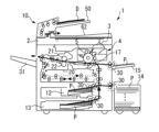
まず、図1、図2にて、画像形成装置における全体の構成・動作について説明する。
図1において、1は画像形成装置としての複写機、10は原稿Dの画像情報を光学的に読み取る画像読取装置、を示す。図2を参照して、画像読取装置10は、画像読取部としての第1CIS80が設置されたスキャナ部2や、シート搬送装置60(原稿自動搬送装置)などで構成されている。
また、3は画像読取装置10で読み取った画像情報に基づいた露光光Lを感光体ドラム5上に照射する露光部(書込部)、4は感光体ドラム5の表面にトナー像(画像)を形成する作像部、7は感光体ドラム5上に形成されたトナー像を用紙P(用紙)に転写する転写部(画像形成部)、を示す。
また、12、13はシートとしての用紙Pを500枚ほど収納可能な給送部、14は大容量の用紙Pを収納可能な大容量給送部、15は手差し用の用紙Pをセット可能な手差し給送部、を示す。
また、17は転写部7に向けて用紙Pを搬送するレジストローラ(タイミングローラ)、20は用紙P上に担持されたトナー像(未定着画像)を定着する定着装置、21は定着装置20に設置された定着ローラ、22は定着装置20に設置された加圧ローラ、を示す。また、31は画像形成装置本体1から排出された用紙Pが積載される排出トレイ、を示す。
First, the overall configuration and operation of the image forming apparatus will be described with reference to FIGS.
In Fig. 1, reference numeral 1 denotes a copying machine serving as an image forming apparatus, and
Also,
Also,
Also,
図1を参照して、画像形成装置本体1における、通常の画像形成時の動作について説明する。
まず、シートとしての原稿Dは、画像読取装置10において、載置部50(原稿台)から搬送(給送)されて、画像読取部としての第1CIS80(密着イメージセンサである。)を通過する。このとき、第1CIS80では、その位置を通過する原稿Dの表面に形成された画像(画像情報)が光学的に読み取られる。
そして、第1CIS80で読み取られた光学的な画像情報は、電気信号に変換された後に、露光部3(書込部)に送信される。そして、露光部3からは、その電気信号の画像情報に基づいたレーザ光等の露光光Lが、作像部4の感光体ドラム5の表面に向けて発せられる。
With reference to FIG. 1, the operation of the image forming apparatus main body 1 during normal image formation will be described.
First, in the
The optical image information read by the
一方、作像部4において、感光体ドラム5は図中の時計方向に回転しており、所定の作像プロセス(帯電工程、露光工程、現像工程)を経て、感光体ドラム5上に画像情報に対応した画像(トナー像)が形成される。
その後、感光体ドラム5の表面に形成された画像は、画像形成部としての転写部7で、レジストローラ17により搬送された用紙P上に転写される。
Meanwhile, in the
Thereafter, the image formed on the surface of the
一方、転写部7(画像形成部)に搬送される用紙Pは、次のように動作する。
まず、画像形成装置1における複数の給送部12~15のうち、1つの給送部が自動又は手動で選択される(例えば、装置本体1内の最上段の給送部12が選択されたものとする。)。そして、給送部12に収納された用紙Pの最上方の1枚が、給送機構30(フィードローラ、ピックアップローラ、バックアップローラ、等で構成されている。)によって給送されて、搬送経路に向けて搬送される。その後、用紙Pは、複数の搬送ローラが配設された搬送経路を通過して、レジストローラ17の位置に達する。
On the other hand, the paper P transported to the transfer unit 7 (image forming unit) operates as follows.
First, one of the
レジストローラ17の位置に達した用紙Pは、感光体ドラム5上に形成された画像と位置合わせをするためにタイミングを合わせて、転写部7(画像形成部)に向けて搬送される。
そして、転写工程後の用紙Pは、転写部7の位置を通過した後に、搬送経路を経て定着装置20に達する。定着装置20に達した用紙Pは、定着ローラ21と加圧ローラ22との間に送入されて、定着ローラ21から受ける熱と双方の部材21、22から受ける圧力とによってトナー像が定着される(定着工程である)。トナー像が定着された定着工程後の用紙Pは、定着ローラ21と加圧ローラ22との間(定着ニップである。)から送出された後に、画像形成装置本体1から排出されて、出力画像として排出トレイ31上に積載されることになる。
こうして、一連の画像形成プロセスが完了する。
The paper P that has reached the position of the
After the transfer process, the paper P passes through the
In this way, a series of image forming processes is completed.
なお、本実施の形態における画像形成装置1は、装置本体の側方に大容量給送部14が設けられている。そして、大容量給送部14が給送部として選択された場合には、大容量給送部14にセットされた用紙Pが、大容量給送部14から給送されて、上述したものと同様に、画像形成プロセスがおこなわれることになる。
また、本実施の形態における画像形成装置1は、大容量給送部14の上方に手差し給送部15が設けられている。そして、手差し給送部15が給送部として選択された場合には、手差し給送部15にセットされた用紙Pが、手差し給送部15から給送されて、上述したものと同様に、画像形成プロセスがおこなわれることになる。
In the image forming apparatus 1 according to the present embodiment, a large-capacity feeder 14 is provided on the side of the apparatus body. When the large-capacity feeder 14 is selected as the feeder, the paper P set in the large-capacity feeder 14 is fed from the large-capacity feeder 14, and the image forming process is carried out in the same manner as described above.
Furthermore, the image forming apparatus 1 in this embodiment is provided with a
次に、図2、図3等を用いて、画像読取装置10について詳述する。
図2に示すように、画像読取装置10は、主に、スキャナ部2とシート搬送装置60(原稿自動搬送装置)とで構成されている。
スキャナ部2は、画像読取部としての第1CIS80、第1コンタクトガラス81、第2コンタクトガラス82、等で構成されている。
シート搬送装置60は、載置部50(原稿台)、原稿排出部62(排紙トレイ)、ピックアップローラ63、分離ローラ64、給送ローラ65、複数の搬送ローラ対66~72、第2の画像読取部としての第2CIS90、圧板75、等で構成されている。
Next, the
As shown in FIG. 2, the
The
The
ここで、載置部50は、上方に開放された空間が形成されていて、ユーザーによって原稿D(シートとしての原稿である。)を載置面に沿って搬送方向上流側から載置できるように構成されている(複数枚の原稿Dの束を積載できるように構成されている)。
また、載置部50は、積載された複数枚の原稿Dのうち、最上方の原稿Dの高さ位置が常に一定になるように、その一部が昇降可能に構成されている。
なお、本実施の形態における載置部50には、載置部50にセットされた原稿Dの幅方向(図1、図2の紙面垂直方向であって、図3~図5の上下方向である。)の位置を定める第1、第2サイドフェンス51、52等が設置されているが、これについては後で図3~図5等を用いて詳しく説明する。
Here, the
Further, the
In the present embodiment, the
原稿排出部62は、載置部50の下方に設置されていて、第1CIS80や第2CIS90によって画像が読み取られた後の原稿D(又は、硬質原稿CD)が排出されて載置されるように構成されている(複数枚の原稿の束が排出・積載されるように構成されている)。
The
また、載置部50から原稿排出部62に至る搬送経路K1、K3には、上流側から順に、ピックアップローラ63、FRR方式給送機構(給送ローラ65、分離ローラ64)、複数の搬送ローラ対66~69、72が設置されている。これらの部材63~69、72は、載置部50に載置された原稿Dを第1CIS80や第2CIS90に向けて搬送して、その後にその原稿Dを原稿排出部62に向けて搬送する搬送手段として機能するものである。
In addition, on the transport paths K1 and K3 leading from the
画像読取部としての第1CISは、密着イメージセンサであって、搬送手段によって搬送されて第1コンタクトガラス81の位置を通過する原稿Dの画像情報を、第1コンタクトガラス81を介して、読み取るものである。
また、対向板としての第1コンタクトガラス81は、ガラスなどの光透過材料で形成されたものであって、搬送経路に設置されている。
The first CIS as an image reading section is a contact image sensor, and reads, via the
The
以下、このように構成された画像読取装置10において、載置部50にセットされた原稿Dの片面に形成された画像のみを読み取る動作(片面読み取り動作)について説明する。
まず、載置部50において、原稿D(上面に画像が形成された状態のものである。)が、基準壁に先端部(搬送方向の先端部である。)が突き当たった状態で積載される。そして、不図示の操作パネルの操作によって原稿Dの画像を読み取る指示(コピー指示)がされると、ピックアップローラ63によって、載置部50上の上方の原稿Dから順次に、FRR方式給送機構(給送ローラ65、分離ローラ64)に向けて搬送される。このとき、複数枚の原稿Dが搬送される可能性があるが、FRR方式の分離によって、最上方の原稿Dのみが分離されて下流側の搬送経路へと送り込まれることになる。
その後、搬送経路に搬送された原稿Dは、回転停止した状態のプルアウトローラ66のニップ部に突き当たって、スキュー補正(斜行補正)がおこなわれる。その後、スキュー補正された原稿Dは、回転開始したプルアウトローラ66によって下流側に搬送されて、第1、第2搬送ローラ対67、68によって第1CIS80(及び、第1コンタクトガラス81)の位置に搬送される。そして、第1CIS80によって原稿Dの画像(画像情報)が光学的に読み取られることになる。
その後、画像が読み取られた原稿Dは、搬送ローラ対69、排出ローラ対72によって、原稿排出部62に排紙される。
このような一連の原稿搬送動作が、載置部50に積載されたすべての原稿Dに対して繰り返しおこなわれることになる。
Hereinafter, an operation of the
First, the document D (with an image formed on the top surface) is loaded on the
Thereafter, the document D transported to the transport path hits the nip portion of the pull-
Thereafter, the document D from which the image has been read is discharged to the
This series of document transport operations is repeated for all documents D loaded on the
なお、原稿Dのオモテ面に形成された画像に加えてウラ面に形成された画像を読み取る場合には、第1CIS80(及び、第1コンタクトガラス81)の位置で、第1CIS80によってオモテ面の画像が読み取られた原稿Dは、その後、第2CIS90(密着イメージセンサである。)の位置に搬送される。そして、第2CIS90によって原稿Dのウラ面の画像が光学的に読み取られることになる。
その後、ウラ面の画像が読み取られた原稿Dは、排出ローラ対72によって、原稿排出部62に排紙される。
なお、第1、第2CIS80、90は、幅方向(図1~図4の紙面垂直方向である。)に延在していて、少なくとも最大サイズの原稿Dの幅方向全域を含むように(最大サイズの原稿Dの画像を幅方向にわたって読み取れるように)構成されている。
When reading an image formed on the back side of the document D in addition to the image formed on the front side, the document D, from which the image on the front side has been read by the first CIS 80 (and the first contact glass 81), is then transported to the position of the second CIS 90 (which is a contact image sensor).Then, the image on the back side of the document D is optically read by the
Thereafter, the document D, from which the image on the back side has been read, is discharged to the
The first and second CISs 80 and 90 extend in the width direction (the direction perpendicular to the paper surface of Figures 1 to 4) and are configured to include at least the entire width of the maximum size original D (so that the image of the maximum size original D can be read across the width).
ここで、本実施の形態における画像読取装置10は、シート搬送装置60によって原稿Dを自動で搬送しながら画像の読み取りをおこなうのではなくて、原稿Dを搬送せずに固定した状態でも画像の読み取りをおこなえるように構成されている。
詳しくは、スキャナ部2の上面(シート搬送装置60の底面に対向する面である。)には、原稿Dを略水平な状態で載置可能な第2コンタクトガラス82が設置されている。第2コンタクトガラス82は、ガラスなどの光透過材料で形成されたものであって、その上面の高さがスキャナ部2の上面の高さに略一致するように構成されている。
また、シート搬送装置60は、第2コンタクトガラス82の上方を開閉可能に構成されていて、その下面には圧板75(公知のものと同様に、適度な弾性を有するものである。)が設置されている。
Here, the
More specifically, a
In addition, the
そして、第2コンタクトガラス82の上面に載置された原稿Dの画像を読み取るときには(原稿Dを固定して画像読取をおこなうときには)、その原稿Dが第2コンタクトガラス82と圧板75との間に挟まれることになる。
具体的に、閉鎖状態のシート搬送装置60を開放状態にして、露呈した第2コンタクトガラス82の上面に原稿D(オモテ面(画像読取面)を下面にした状態である。)をセットする。その後、第2コンタクトガラス82上にセットされた原稿Dを、圧板75との間で挟むように、開放状態のシート搬送装置60を閉鎖状態にする。
そして、不図示の操作パネルの操作によって原稿Dの画像を読み取る指示(コピー指示)がされると、第1CIS80(又は、専用に設けたCIS)が第2コンタクトガラス82の下面に接しながら図2の右方向(スキャン方向である。)に移動して、原稿Dの全面の画像が光学的に読み取られることになる。
When reading the image of the original D placed on the upper surface of the second contact glass 82 (when the original D is fixed and image reading is performed), the original D is sandwiched between the
Specifically, the
Then, when an instruction to read the image of the original D (copy instruction) is given by operating an operation panel (not shown), the first CIS 80 (or a dedicated CIS) moves to the right in Figure 2 (the scanning direction) while in contact with the underside of the
以下、図3~図5等を用いて、本実施の形態におけるシート搬送装置60(画像読取装置10、画像形成装置1)の、特徴的な構成・動作について詳述する。
先に図2等を用いて説明したように、シート搬送装置60は、所定の搬送方向にシートとしての原稿Dを搬送するものである。
図3等に示すように、本実施の形態におけるシート搬送装置60には、載置部50(原稿台)、一対の第1サイドフェンス51、一対の第2サイドフェンス52、一対の付勢部材としての圧縮スプリング54、一対のガイドフェンス53、などが設けられている。
Hereinafter, the characteristic configuration and operation of the sheet conveying device 60 (
As previously described with reference to FIG. 2 and the like, the
As shown in Figure 3, the
載置部50は、シートとしての原稿Dが載置される部分である。そして、載置部50に載置された原稿Dが、ピックアップローラ63によって搬送方向(図3の黒矢印方向である。)に搬送されることになる。
The
一対の第1サイドフェンス51は、載置部50において幅方向両端部にそれぞれ設置されている。
この一対の第1サイドフェンス51は、それぞれ、載置部50の載置面から垂直方向に起立するとともに搬送方向に延びるように形成されたフェンス状部材である。一対のサイドフェンス51は、載置部50に載置される原稿D(シート)の幅方向中央位置に対応する位置(図3において一点鎖線で示す位置である。)から幅方向両端部に向けて互いに同等の距離離れた位置に固定されている。
また、一対の第1サイドフェンス51は、搬送可能な最大サイズの原稿DL(図5参照)の幅方向の位置を規制する(定める)ものである。すなわち、一対の第1サイドフェンス51は、原稿Dの幅方向両端部を挟み込んで、その位置を定めるものである。
詳しくは、一対の第1サイドフェンス51に後述する一対の第2サイドフェンス52が近接した状態(図5(B)の状態である。)であるとき、搬送可能な最大サイズの原稿DL(シート)の幅方向の位置が規制されることになる。すなわち、サイドフェンス51は、ガイドフェンス53、第2サイドフェンス52と連動し一体となってサイドフェンス51が最大サイズの原稿DLの幅方向の位置まで移動可能で、その位置を定め規制するものである。
The pair of
The pair of
The pair of
More specifically, when a pair of second side fences 52 (described later) are in close proximity to a pair of first side fences 51 (as shown in FIG. 5B), the widthwise position of the maximum size document DL (sheet) that can be transported is restricted. That is, the
一対の第2サイドフェンス52は、それぞれ、載置部50の載置面から垂直方向に起立するとともに搬送方向に延びるように形成されたフェンス状部材である。
一対の第2サイドフェンス52は、一対の第1サイドフェンス51に対して幅方向中央部の側(一対のサイドフェンス51の内側である。)において幅方向に移動可能に設置されていて、載置部50に載置された原稿D(シート)の幅方向の位置を規制可能に構成されている。
The pair of
The pair of
具体的に、一対の第2サイドフェンス52は、原稿Dの幅方向両端部を挟み込んで、その位置を定めるものである。第2サイドフェンス52は、その搬送方向の長さが、第1サイドフェンス51の搬送方向の長さよりも短くなるように形成されている。第2サイドフェンス52の搬送方向下流側(図3の左側である。)の端部の位置は、第1サイドフェンス51の搬送方向下流側の端部の位置とほぼ同じである。
また、図示は省略するが、第2サイドフェンス52は、その底部に形成された複数のボス部が、載置部50の載置面において幅方向に延びるように形成された溝部に嵌合して、その溝部に沿ってスライド移動可能に構成されている。第2サイドフェンス52は、溝部の範囲内(第1サイドフェンス51と図3に示す第2サイドフェンス52の位置との間である。)で移動可能に構成されている。
なお、図3、図4に示す第2サイドフェンス52の位置は、搬送可能な最小サイズ(例えば、名刺サイズである。)の原稿DSの幅方向の位置を定める位置である。
Specifically, the pair of
Although not shown, the
The position of the
圧縮スプリング54は、第2サイドフェンス52を幅方向中央部の側に移動させるように付勢する付勢部材として機能するものである。
詳しくは、圧縮スプリング54は、一端側が第1サイドフェンス51の内壁面に接続され、他端側が第2サイドフェンス52の外壁面に接続されている。圧縮スプリング54の付勢力は、載置部50に載置された原稿Dを撓ませない程度の力であって、第2サイドフェンス52を幅方向中央部側に移動させる程度の力に設定されている。
このような構成により、第2サイドフェンス52は、載置部50に原稿Dがセットされていない状態のとき、図3に示す位置を基準位置として止まることになる。そして、載置部50に最小サイズよりも大きな幅方向サイズの原稿Dがセットされると、その原稿Dの幅方向サイズに合わせて第2サイドフェンス52が幅方向に移動して、その原稿Dの幅方向の位置が定められることになる。
なお、本実施の形態では、付勢部材として圧縮スプリング54を用いたが、付勢部材はこれに限定されることなく、板バネや弾性ゴムなどを付勢部材として用いることもできる。
The
More specifically, one end of the
3 as a reference position when no document D is set on the
In this embodiment, the
ガイドフェンス53は、第2サイドフェンス52の搬送方向上流側の端部(第1の連結部53aの位置である。)と、第1サイドフェンス51において上述した端部よりも搬送方向上流側の位置(第2の連結部53bの位置である。)と、を中継するように設置されている。
そして、図5等を参照して、ガイドフェンス53は、第2サイドフェンス52の幅方向の移動に連動して第1サイドフェンス51に対する傾斜角が可変される。
The
5 and other drawings, the inclination angle of the
詳しくは、ガイドフェンス53は、載置部50の載置面から垂直方向に起立して、その内壁面が第1サイドフェンス51の内壁面と第2サイドフェンス52の内壁面とに繋がるように形成されたフェンス状部材である。
第2サイドフェンス52とガイドフェンス53とは、第1の連結部53aで連結されている。この第1の連結部53aは、ヒンジ機構などであって、第2サイドフェンス52に対してガイドフェンス53を相対的に回動させるように構成されている。
第1サイドフェンス51とガイドフェンス53とは、第2の連結部53bで連結されている。この第2の連結部53bは、第1サイドフェンス51に形成されたガイド部に沿って搬送方向(図3、図4の左右方向である。)に移動可能に構成されている。
In detail, the
The
The
以下、図4を用いて、幅方向サイズが最小である原稿DSが載置部50にセットされる動作(操作)の一例について説明する。
まず、ユーザーは、最小サイズの原稿DSを把持した状態で、図4の右側(搬送方向上流側)から左側(搬送航行下流側)に向けて原稿DSを押し込む。このとき、図4(A)に示すように、原稿DSの先端の角部が第1サイドフェンス51と第2サイドフェンス52との間に位置した状態で押し込まれても、原稿DSの角部がガイドフェンス53に接触することになる。そして、図4(B)に示すように、原稿DSは、その角部がガイドフェンス53の傾斜面に沿いながら、斜め矢印方向に移動して、一対の第2サイドフェンス52の間に導かれることになる。そして、その状態で原稿DSが押し込まれて、最終的に一対の第2サイドフェンス52の間に挿入されて、原稿DSの幅方向の位置が定められることになる。
Hereinafter, an example of the operation (operation) for setting the original document DS having the smallest width size on the
First, the user, holding a minimum-sized document DS, pushes the document DS from the right side (upstream side in the transport direction) to the left side (downstream side in the transport direction) in Fig. 4. At this time, even if the document DS is pushed in with the corner of the leading edge positioned between the
なお、図6に比較例として示すシート搬送装置160のように、ガイドフェンス53が設けられていないものは、原稿DSの先端の角部が第1サイドフェンス51と第2サイドフェンス52との間に位置した状態で押し込まれてしまうと、原稿DSの先端が第2サイドフェンス52にぶつかって、原稿DSの先端にキズがついてしまうことになる。そして、そのような不具合を避けるように、一対の第2サイドフェンス52の間に原稿DSが収まるように、原稿DSをセットする作業は、とても注意のいる難しい作業になる。
In addition, in a sheet conveying device that does not have a
以下、図5を用いて、幅方向サイズが最大である原稿DLが載置部50にセットされる動作(操作)について説明する。
まず、ユーザーは、最大サイズの原稿DLを把持した状態で、図5の右側(搬送方向上流側)から左側(搬送航行下流側)に向けて原稿DLを押し込む。このとき、図5(A)に示すように、原稿DLの先端の角部がガイドフェンス53(第1サイドフェンス51に近い位置である。)に接触することになる。そして、ガイドフェンス53は、原稿DLによって押し込まれながら、第1サイドフェンス51に沿うように傾斜角を可変していくことになる。そして、そのようなガイドフェンス53の変位にともない、図5(B)に示すように、第2サイドフェンス52は幅方向端部に向けて移動して、その間に原稿DLを導くことになる。そして、最終的に一対の第1、第2サイドフェンス51、52の間に原稿DLが挿入されて、原稿DLの幅方向の位置が定められることになる。
なお、最大サイズよりも小さくて最小サイズよりも大きなサイズの原稿Dが載置部50にセットされる場合には、基本的に図5と同じような動作によって、その原稿Dの幅方向サイズに合わせて第2サイドフェンス52が移動して、その位置で原稿Dの幅方向の位置を定めることになる。
Hereinafter, the operation (manipulation) for setting the document DL having the maximum width size on the
First, the user, holding the maximum-sized document DL, pushes the document DL from the right side (upstream side in the transport direction) to the left side (downstream side in the transport direction) in FIG. 5. At this time, as shown in FIG. 5A, the corner of the leading edge of the document DL comes into contact with the guide fence 53 (located close to the first side fence 51). Then, while being pushed by the document DL, the
When an original document D smaller than the maximum size and larger than the minimum size is set on the
このように、本実施の形態におけるシート搬送装置60は、大サイズ用の第1サイドフェンス51や小サイズ用の第2サイドフェンス52の他に、第2サイドフェンス52を付勢する圧縮スプリング54や、第1サイドフェンス51と第2サイドフェンス52とを中継するガイドフェンス53を設けている。そのため、載置部50にセットされる原稿Dの幅方向サイズに応じて第2サイドフェンス52を起こしたり倒したりする必要がなく、また先に図6を用いて説明したように原稿Dが第2サイドフェンス52にぶつかってしまう不具合が生じることなく、原稿Dを載置部50にセットするときの作業性が良好になる。すなわち、載置部50にセットされる原稿Dの幅方向サイズに関わらず、種々の幅方向サイズの原稿Dのすべてに対して、載置部50に原稿Dをセットするときの作業性が向上することになる。
In this way, the
<変形例1>
図7に示すように、変形例1におけるシート搬送装置60は、ロック機構としてのストッパ部57と、ロック解除機構としての操作部93(カム機構)と、が設けられている。
なお、図7は、次の変形例2の説明で用いる図8と同様に、載置部50の部分を搬送方向下流側からみた正面図である。
図7(A)に示すように、ストッパ部57は、圧縮スプリング54(付勢部材)による付勢に抗するように第1サイドフェンス51に第2サイドフェンス52が近接したロック状態を維持するためのロック機構として機能するものである。詳しくは、ストッパ部57は、載置部50の載置面よりも下方の位置で、第2サイドフェンス52の下端部に係合して、圧縮スプリング54の付勢による第2サイドフェンス52の幅方向中央部側への移動を制限するものである。なお、ストッパ部57は、図7(B)、(C)に示すように、支軸を中心にして回動可能に構成されている。
これに対して、操作部93は、カム機構の一部として設けられていて、ストッパ部57(ロック機構)によるロック状態を手動で解除するためのロック解除機構として機能するものである。詳しくは、カム機構はストッパ部57に係合してストッパ部57を支軸を中心に回動させるように構成されている。そして、操作部93は、そのカム機構を手動操作できるように構成されている。
このような構成により、ユーザーによる操作部93の手動操作により、カム機構を稼働させて、図7(A)に示すようにストッパ部57によって第2サイドフェンス52がロックされた状態と、図7(B)に示すようにストッパ部57による第2サイドフェンス52のロック状態が解除された状態と、を切り替えることになる。
そして、これにより、小サイズの原稿DSをほとんど用いることがないユーザーに対して、図7(A)に示すような第2サイドフェンス52が第1サイドフェンス51に近接したロック状態を維持することにより、そのユーザーに対する大サイズの原稿DLのセット性を向上させることができる。そして、そのユーザーは、使用頻度の少ない小サイズの原稿DSを載置部50にセットする場合に、操作部93を操作して第2サイドフェンス52のロック状態を解除して、先に図4等を用いて説明したようなセット方法で、小サイズの原稿DSのセットをおこなうことになる。
<Modification 1>
As shown in FIG. 7, a
7 is a front view of the
As shown in Fig. 7A, the
On the other hand, the operating
With this configuration, the user can manually operate the operating
Thus, for a user who rarely uses small-sized documents DS, the ease of setting a large-sized document DL for that user can be improved by maintaining the
なお、図7に示すように、変形例1におけるシート搬送装置60には、上述したガイドフェンス53(第1ガイドフェンス)とは別に、一対の第2ガイドフェンス55が設置されている。
この第2ガイドフェンス55は、第2サイドフェンス52の上端部(第1の第2連結部55aの位置である。)と、第1サイドフェンス51において上述した上端部よりも上方の位置(第2の第2連結部55bの位置である。)と、を中継するように設置されている。そして、第2ガイドフェンス55は、第2サイドフェンス52の幅方向の移動に連動して第1サイドフェンス51に対する傾斜角が可変される。
詳しくは、第2ガイドフェンス55は、その内壁面が第1サイドフェンス51の内壁面と第2サイドフェンス52の内壁面とに繋がるように形成されたフェンス状部材である。第2ガイドフェンス55は、搬送方向に広がる傾斜面を有するフェンス部材である。
第2サイドフェンス52と第2ガイドフェンス55とは、第1の第2連結部55aで連結されている。この第1の第2連結部55aは、ヒンジ機構などであって、第2サイドフェンス52に対して第2ガイドフェンス55を相対的に回動させるように構成されている。
第1サイドフェンス51と第2ガイドフェンス55とは、第2の第2連結部55bで連結されている。この第2の第2連結部55bは、第1サイドフェンス51に形成されたガイド部に沿って上下方向に移動可能に構成されている。
このように構成することで、図7(C)に示すように、ストッパ部57による第2サイドフェンス52のロックが解除された状態で、ユーザーが載置部50の上方から下方に向けて原稿D(小サイズよりも大きなサイズの原稿である。)をセットする場合に、まず、原稿Dの幅方向両端部の角部が第2ガイドフェンス55に接触することになる。そして、第2ガイドフェンス55は、原稿Dによって押し込まれながら、第1サイドフェンス51に近づくように傾斜角を可変していくことになる。そして、そのような第2ガイドフェンス55の変位にともない、第2サイドフェンス52は幅方向端部に向けて移動して、その間に原稿Dを導くことになる。そして、最終的に一対の第2サイドフェンス52の間に挿入されて、原稿Dの幅方向の位置が定められることになる。
なお、小サイズの原稿DSや大サイズの原稿DLが上方からセットされる場合も、上下方向と搬送方向との違いはあるが、先に図4,図5等を用いて説明したものと同じ動作原理で、その原稿がセットされることになる。
したがって、載置部50にセットされる原稿Dの幅方向サイズに関わらず、載置部50に原稿Dをセットするときの作業性が向上する。
As shown in FIG. 7, the
The
More specifically, the
The
The
With this configuration, when the user sets the document D (a document larger than the small size) from above to below the
Incidentally, when a small-sized original DS or a large-sized original DL is set from above, the original is set according to the same operating principle as that previously explained using Figures 4 and 5, although there is a difference between the up-down direction and the conveying direction.
Therefore, regardless of the width direction size of the document D to be set on the
<変形例2>
図8に示すように、変形例2におけるシート搬送装置60にも、図7に示したものと同様に、ロック機構としてのストッパ部57や、第2ガイドフェンス55、が設けられている。
そして、変形例2のものは、変形例1のものとは異なり、ロック解除機構として機能するモータ94(カム機構)と、ストッパ部57(ロック機構)によるロック状態の有無を検知可能な検知手段としての検知センサ95と、が設けられている。
図8(A)~(C)を参照して、モータ94は、カム機構を自動で稼働するカム機構の一部として設けられていて、ストッパ部57(ロック機構)によるロック状態を自動で解除するためのロック解除機構として機能するものである。詳しくは、カム機構はストッパ部57に係合してストッパ部57を支軸を中心に回動させるように構成されている。そして、モータ94は、そのカム機構を駆動できるように構成されている。
このような構成により、ユーザーによる操作パネル(不図示)の操作によってモータ94を駆動させて、図8(A)に示すようにストッパ部57によって第2サイドフェンス52がロックされた状態と、図8(B)に示すようにストッパ部57による第2サイドフェンス52のロック状態が解除された状態と、が切り替えられることになる。
そして、これにより、先に変形例1で説明したものと同様、小サイズの原稿DSをほとんど用いることがないユーザーに対しての使い勝手を向上させることができる。
なお、変形例2では、ストッパ部57(特に、大きく変位する部分である。)の下方に、ストッパ部57との対向距離を光学的に検知可能な測距センサなどの検知センサ95が設けられている。そして、この検知センサ95によって、図8(A)、(C)に示すようにストッパ部57が上方位置(ロック位置)に回動した状態と、図8(B)に示すようにストッパ部57が下方位置(ロック解除位置)に回動した状態と、を検知しながら、モータ94の駆動制御をおこなって、ロック状態とロック解除状態との切替不良を防止している。
<
As shown in FIG. 8, a
Unlike variant 1,
8(A) to 8(C), the
With this configuration, the user can drive the
As a result, similarly to what has been explained above in the first modified example, it is possible to improve usability for users who rarely use small-sized originals DS.
In the second modification, a
以上説明したように、本実施の形態におけるシート搬送装置60は、所定の搬送方向にシートを搬送するシート搬送装置であって、原稿D(シート)が載置される載置部50と、載置部50において幅方向両端部にそれぞれ設置された一対の第1サイドフェンス51が設けられている。また、載置部50に載置された原稿Dの幅方向の位置を規制可能な一対の第2サイドフェンス52が、一対の第1サイドフェンス51に対して幅方向中央部の側において幅方向に移動可能に設置されている。また、第2サイドフェンス52を幅方向中央部の側に移動させるように付勢する圧縮スプリング54(付勢部材)が設けられている。さらに、第2サイドフェンス52の幅方向の移動に連動して第1サイドフェンス51に対する傾斜角が可変されるガイドフェンス53が、第2サイドフェンス52の搬送方向上流側の端部と、第1サイドフェンス51において前記端部よりも搬送方向上流側の位置と、を中継するように設置されている。
これにより、幅方向サイズの異なる種々の原稿D(シート)に対して、載置部50にセットするときの作業性が良好になる。
As described above, the
This improves the ease of operation when setting various documents D (sheets) having different widthwise sizes on the
なお、本実施の形態では、モノクロの画像形成装置1に設置されるシート搬送装置60(画像読取装置10)に対して本発明を適用したが、カラーの画像形成装置に設置されるシート搬送装置(画像読取装置)に対しても当然に本発明を適用することができる。
また、本実施の形態では、電子写真方式の画像形成装置1に設置されるシート搬送装置60(画像読取装置10)に対して本発明を適用したが、本発明の適用はこれに限定されることなく、その他の方式の画像形成装置(例えば、インクジェット方式の画像形成装置や、孔版印刷機などである。)に設置されるシート搬送装置(画像読取装置)に対しても本発明を適用することができる。
また、本実施の形態では、シートとしての原稿Dを搬送するシート搬送装置60に対して本発明を適用したが、本発明の適用はこれに限定されることなく、例えば、シートとしての用紙Pを搬送するシート搬送装置としての給送部12~15に対しても本発明を適用することができる。
そして、それらのような場合であっても、本実施の形態のものと同様の効果を得ることができる。
In this embodiment, the present invention is applied to a sheet conveying device 60 (image reading device 10) installed in a monochrome image forming apparatus 1, but the present invention can naturally also be applied to a sheet conveying device (image reading device) installed in a color image forming apparatus.
Furthermore, in this embodiment, the present invention is applied to a sheet conveying device 60 (image reading device 10) installed in an electrophotographic image forming apparatus 1, but the application of the present invention is not limited to this, and the present invention can also be applied to sheet conveying devices (image reading devices) installed in other types of image forming apparatuses (e.g., inkjet image forming apparatuses, stencil printers, etc.).
In addition, in this embodiment, the present invention is applied to a
Even in such cases, the same effects as those of this embodiment can be obtained.
なお、本発明が本実施の形態に限定されず、本発明の技術思想の範囲内において、本実施の形態の中で示唆した以外にも、本実施の形態は適宜変更され得ることは明らかである。また、前記構成部材の数、位置、形状等は本実施の形態に限定されず、本発明を実施する上で好適な数、位置、形状等にすることができる。 It is clear that the present invention is not limited to this embodiment, and that within the scope of the technical concept of the present invention, this embodiment may be modified as appropriate in ways other than those suggested in this embodiment. Furthermore, the number, position, shape, etc. of the components are not limited to this embodiment, and may be any number, position, shape, etc. that is suitable for implementing the present invention.
なお、本願において、「シート」とは、画像読取装置10のシート搬送装置60にセットされる原稿Dの他、給送部12、13や大容量給送部14や手差し給送部15に設置される用紙Pなども含むものと定義する。
In this application, the term "sheet" is defined to include not only the document D set in the
1 画像形成装置(画像形成装置本体)、
2 スキャナ部、
10 画像読取装置、
50 載置部、
51 第1サイドフェンス(第1規制部材)、
52 第2サイドフェンス(第2規制部材)、
53 ガイドフェンス(ガイド部材)、
53a、53b 連結部、
54 圧縮スプリング(付勢部材)、
55 第2ガイドフェンス、
55a、55b 第2連結部、
57 ストッパ部(ロック機構)、
60 シート搬送装置、
93 操作部(ロック解除機構)、
94 モータ(ロック解除機構)、
95 検知センサ(検知手段)、
D、DS、DL 原稿(シート)。
1 Image forming apparatus (image forming apparatus main body),
2 scanner unit,
10 Image reading device,
50 placement portion,
51 First side fence (first restricting member),
52 second side fence (second restricting member),
53 Guide fence (guide member),
53a, 53b connection part,
54 compression spring (biasing member),
55 Second guide fence,
55a, 55b second connection part,
57 Stopper portion (lock mechanism),
60 sheet conveying device,
93 Operation unit (unlock mechanism),
94 Motor (unlock mechanism),
95 Detection sensor (detection means),
D, DS, DL Manuscript (sheet).
なお、本発明における態様は、例えば、以下の通り付記1~8の組み合わせとすることもできる。
(付記1)
所定の搬送方向にシートを搬送するシート搬送装置であって、
シートが載置される載置部と、
前記載置部において幅方向両端部にそれぞれ設置された一対の第1サイドフェンスと、
前記一対の第1サイドフェンスに対して幅方向中央部の側において幅方向に移動可能に設置されて、前記載置部に載置されたシートの幅方向の位置を規制可能な一対の第2サイドフェンスと、
前記第2サイドフェンスを幅方向中央部の側に移動させるように付勢する付勢部材と、
前記第2サイドフェンスの搬送方向上流側の端部と、前記第1サイドフェンスにおいて前記端部よりも搬送方向上流側の位置と、を中継するように設置されて、前記第2サイドフェンスの幅方向の移動に連動して前記第1サイドフェンスに対する傾斜角が可変されるガイドフェンスと、
を備えたことを特徴とするシート搬送装置。
(付記2)
前記一対の第1サイドフェンスは、前記載置部に載置されるシートの幅方向中央位置に対応する位置から幅方向両端部に向けて互いに同等の距離離れた位置に固定されたことを特徴とする付記1に記載のシート搬送装置。
(付記3)
前記一対の第1サイドフェンスに前記一対の第2サイドフェンスが近接した状態であるとき、搬送可能な最大サイズのシートの幅方向の位置が規制されることを特徴とする付記1又は付記2に記載のシート搬送装置。
(付記4)
前記付勢部材による付勢に抗するように前記第1サイドフェンスに前記第2サイドフェンスが近接したロック状態を維持するためのロック機構と、
前記ロック機構による前記ロック状態を解除するためのロック解除機構と、
を備えたことを特徴とする付記1~付記3のいずれかに記載のシート搬送装置。
(付記5)
前記ロック解除機構は、前記ロック機構による前記ロック状態を手動又は自動で解除する機構であることを特徴とする付記4に記載のシート搬送装置。
(付記6)
前記ロック機構による前記ロック状態の有無を検知可能な検知手段を備えたことを特徴とする付記4又は付記5に記載のシート搬送装置。
(付記7)
付記1~付記6のいずれかに記載のシート搬送装置と、
前記シート搬送装置によって搬送されたシートの表面に形成された画像を読み取る画像読取部と、
を備えたことを特徴とする画像読取装置。
(付記8)
付記1~付記6のいずれかに記載のシート搬送装置を備えたことを特徴とする画像形成装置。
In addition, the aspect of the present invention can also be a combination of Supplementary Notes 1 to 8 as follows, for example.
(Appendix 1)
A sheet conveying device that conveys a sheet in a predetermined conveying direction,
a placement section on which a sheet is placed;
A pair of first side fences are provided at both ends of the placement section in the width direction,
a pair of second side fences that are disposed on the width direction center side of the pair of first side fences so as to be movable in the width direction and that can regulate the width direction position of the sheet placed on the placement section;
a biasing member that biases the second side fence toward a width direction center portion;
a guide fence provided to relay an end portion of the second side fence on an upstream side in the conveying direction and a position on the first side fence upstream of the end portion in the conveying direction, the guide fence having an inclination angle with respect to the first side fence varied in response to movement of the second side fence in a width direction;
A sheet conveying device comprising:
(Appendix 2)
The sheet conveying device described in Appendix 1, characterized in that the pair of first side fences are fixed at positions spaced equal distances from each other toward both widthwise ends from a position corresponding to the widthwise center position of the sheet placed on the loading section.
(Appendix 3)
The sheet conveying device described in Appendix 1 or
(Appendix 4)
a locking mechanism for maintaining a locked state in which the second side fence is close to the first side fence against the biasing force of the biasing member;
an unlocking mechanism for releasing the locked state by the locking mechanism;
4. The sheet conveying device according to claim 1, further comprising:
(Appendix 5)
The sheet conveying device according to
(Appendix 6)
The sheet conveying device according to
(Appendix 7)
A sheet conveying device according to any one of Supplementary Note 1 to Supplementary Note 6,
an image reading unit that reads an image formed on a surface of the sheet conveyed by the sheet conveying device;
An image reading device comprising:
(Appendix 8)
7. An image forming apparatus comprising the sheet conveying device according to claim 1.
Claims (8)
シートが載置される載置部と、
前記載置部において幅方向両端部にそれぞれ設置された一対の第1サイドフェンスと、
前記一対の第1サイドフェンスに対して幅方向中央部の側において幅方向に移動可能に設置されて、前記載置部に載置されたシートの幅方向の位置を規制可能な一対の第2サイドフェンスと、
前記第2サイドフェンスを幅方向中央部の側に移動させるように付勢する付勢部材と、
前記第2サイドフェンスの搬送方向上流側の端部と、前記第1サイドフェンスにおいて前記端部よりも搬送方向上流側の位置と、を中継するように設置されて、前記第2サイドフェンスの幅方向の移動に連動して前記第1サイドフェンスに対する傾斜角が可変されるガイドフェンスと、
を備えたことを特徴とするシート搬送装置。 A sheet conveying device that conveys a sheet in a predetermined conveying direction,
a placement section on which a sheet is placed;
A pair of first side fences are provided at both ends of the placement section in the width direction,
a pair of second side fences that are disposed on the width direction center side of the pair of first side fences so as to be movable in the width direction and that can regulate the width direction position of the sheet placed on the placement section;
a biasing member that biases the second side fence toward a width direction center portion;
a guide fence provided to relay an end portion of the second side fence on an upstream side in the conveying direction and a position on the first side fence upstream of the end portion in the conveying direction, the guide fence having an inclination angle with respect to the first side fence varied in response to movement of the second side fence in a width direction;
A sheet conveying device comprising:
前記ロック機構による前記ロック状態を解除するためのロック解除機構と、
を備えたことを特徴とする請求項1又は請求項2に記載のシート搬送装置。 a locking mechanism for maintaining a locked state in which the second side fence is close to the first side fence against the biasing force of the biasing member;
an unlocking mechanism for releasing the locked state by the locking mechanism;
3. The sheet conveying device according to claim 1, further comprising:
前記シート搬送装置によって搬送されたシートの表面に形成された画像を読み取る画像読取部と、
を備えたことを特徴とする画像読取装置。 The sheet conveying device according to claim 1 or 2,
an image reading unit that reads an image formed on a surface of the sheet conveyed by the sheet conveying device;
An image reading device comprising:
Priority Applications (1)
| Application Number | Priority Date | Filing Date | Title |
|---|---|---|---|
| JP2023148363A JP2025041210A (en) | 2023-09-13 | 2023-09-13 | SHEET CONVEYING DEVICE, IMAGE READING DEVICE, AND IMAGE FORMING DEVICE |
Applications Claiming Priority (1)
| Application Number | Priority Date | Filing Date | Title |
|---|---|---|---|
| JP2023148363A JP2025041210A (en) | 2023-09-13 | 2023-09-13 | SHEET CONVEYING DEVICE, IMAGE READING DEVICE, AND IMAGE FORMING DEVICE |
Publications (1)
| Publication Number | Publication Date |
|---|---|
| JP2025041210A true JP2025041210A (en) | 2025-03-26 |
Family
ID=95105085
Family Applications (1)
| Application Number | Title | Priority Date | Filing Date |
|---|---|---|---|
| JP2023148363A Pending JP2025041210A (en) | 2023-09-13 | 2023-09-13 | SHEET CONVEYING DEVICE, IMAGE READING DEVICE, AND IMAGE FORMING DEVICE |
Country Status (1)
| Country | Link |
|---|---|
| JP (1) | JP2025041210A (en) |
-
2023
- 2023-09-13 JP JP2023148363A patent/JP2025041210A/en active Pending
Similar Documents
| Publication | Publication Date | Title |
|---|---|---|
| JP5939459B2 (en) | Sheet material conveying apparatus, image reading apparatus, and image forming apparatus | |
| US8579282B2 (en) | Image forming apparatus | |
| JP6540041B2 (en) | Image reading apparatus and image forming apparatus | |
| CN112055125A (en) | Sheet conveying device, original reading device, and image forming apparatus | |
| US20170302814A1 (en) | Image reading apparatus and image forming apparatus | |
| JP2017218273A (en) | Automatic document feeder, image reading apparatus, and image forming apparatus | |
| JP5823454B2 (en) | Paper feeding device and image forming apparatus | |
| JP2024178253A (en) | Image reading device and image forming device | |
| US10183818B2 (en) | Sheet loader, image forming apparatus incorporating the sheet loader, and image reader incorporating the sheet loader | |
| US6055410A (en) | Bypass/stack sheet-feeding configuration for miniaturizing electrostatographic apparatus | |
| JP5504140B2 (en) | Image forming apparatus | |
| JP2019040127A (en) | Lock mechanism for movable unit and sheet conveying device including the same, and image forming apparatus | |
| JP2023178820A (en) | sheet feeding device | |
| JP2013249162A (en) | Image reader and image forming apparatus | |
| JP2025041210A (en) | SHEET CONVEYING DEVICE, IMAGE READING DEVICE, AND IMAGE FORMING DEVICE | |
| JP5289286B2 (en) | Sheet supply tray and image forming apparatus | |
| CN118317025A (en) | Sheet feeding device, image reading device, and image forming apparatus | |
| JP7723906B2 (en) | Image reading device and image forming device | |
| US12459762B2 (en) | Sheet feeding device, image reading device and image forming apparatus | |
| JP7837750B2 (en) | Sheet transport device, and image reading device and image forming device equipped therewith. | |
| JP7508273B2 (en) | Image forming device | |
| JP2019218178A (en) | Image forming system and control method thereof | |
| JP7455672B2 (en) | Image reading device and image forming device | |
| JP6102197B2 (en) | Automatic document feeder and image forming apparatus having the same | |
| JP7314640B2 (en) | Sheet feeding device, automatic document feeder and image forming device |