JP2025041207A - Accelerating Cavity - Google Patents

Accelerating Cavity Download PDF

Info

Publication number
JP2025041207A
JP2025041207A JP2023148359A JP2023148359A JP2025041207A JP 2025041207 A JP2025041207 A JP 2025041207A JP 2023148359 A JP2023148359 A JP 2023148359A JP 2023148359 A JP2023148359 A JP 2023148359A JP 2025041207 A JP2025041207 A JP 2025041207A
Authority
JP
Japan
Prior art keywords
switch member
housing
central axis
gap
acceleration cavity
Prior art date
Legal status (The legal status is an assumption and is not a legal conclusion. Google has not performed a legal analysis and makes no representation as to the accuracy of the status listed.)
Pending
Application number
JP2023148359A
Other languages
Japanese (ja)
Other versions
JP2025041207A5 (en
Inventor
優志 木村
Masashi Kimura
博史 原
Hiroshi Hara
伸之 重岡
Nobuyuki Shigeoka
明啓 宮本
Akihiro Miyamoto
東明 菅野
Tomei Sugano
Current Assignee (The listed assignees may be inaccurate. Google has not performed a legal analysis and makes no representation or warranty as to the accuracy of the list.)
Mitsubishi Heavy Industries Machinery Systems Co Ltd
Original Assignee
Mitsubishi Heavy Industries Machinery Systems Co Ltd
Priority date (The priority date is an assumption and is not a legal conclusion. Google has not performed a legal analysis and makes no representation as to the accuracy of the date listed.)
Filing date
Publication date
Application filed by Mitsubishi Heavy Industries Machinery Systems Co Ltd filed Critical Mitsubishi Heavy Industries Machinery Systems Co Ltd
Priority to JP2023148359A priority Critical patent/JP2025041207A/en
Priority to PCT/JP2024/029381 priority patent/WO2025057665A1/en
Publication of JP2025041207A publication Critical patent/JP2025041207A/en
Publication of JP2025041207A5 publication Critical patent/JP2025041207A5/ja
Pending legal-status Critical Current

Links

Images

Classifications

    • HELECTRICITY
    • H05ELECTRIC TECHNIQUES NOT OTHERWISE PROVIDED FOR
    • H05HPLASMA TECHNIQUE; PRODUCTION OF ACCELERATED ELECTRICALLY-CHARGED PARTICLES OR OF NEUTRONS; PRODUCTION OR ACCELERATION OF NEUTRAL MOLECULAR OR ATOMIC BEAMS
    • H05H13/00Magnetic resonance accelerators; Cyclotrons
    • H05H13/04Synchrotrons
    • HELECTRICITY
    • H05ELECTRIC TECHNIQUES NOT OTHERWISE PROVIDED FOR
    • H05HPLASMA TECHNIQUE; PRODUCTION OF ACCELERATED ELECTRICALLY-CHARGED PARTICLES OR OF NEUTRONS; PRODUCTION OR ACCELERATION OF NEUTRAL MOLECULAR OR ATOMIC BEAMS
    • H05H9/00Linear accelerators
    • H05H9/04Standing-wave linear accelerators

Landscapes

  • Physics & Mathematics (AREA)
  • Engineering & Computer Science (AREA)
  • Plasma & Fusion (AREA)
  • Spectroscopy & Molecular Physics (AREA)
  • Particle Accelerators (AREA)

Abstract

To provide an acceleration cavity capable of switching energy of charged particles without using a complex mechanism.SOLUTION: An acceleration cavity comprises: a body that is in an electrically conductive cylindrical shape and includes a plurality of division members obtained by division using a plane along the central axis so that division surfaces along the plane are provided in a state of facing each other with a gap; a plurality of cell parts that are disposed inside the body in a state of being arranged in the axial direction of the central axis of the body and are communicated with each other using a communication part through which charged particles can pass; and a switch member that is disposed in the gap of the body, is movable in the gap along the plane, and performs movement to switch the magnitude of an electric field for accelerating the charged particles.SELECTED DRAWING: Figure 2

Description

本開示は、加速空洞に関する。 This disclosure relates to acceleration cavities.

加速空洞は、高周波が入力されることで内部に加速電界を発生させ、電子等の荷電粒子を加速させる。このような加速空洞として、例えば中心軸の軸方向に並ぶ複数のセル部が設けられ、セル部同士が連通部により連通された構成が知られている(例えば、特許文献1参照)。 When high frequency waves are input into an acceleration cavity, an acceleration electric field is generated inside the cavity, accelerating charged particles such as electrons. For example, an acceleration cavity of this type is known to have a configuration in which multiple cell sections are arranged in the axial direction of the central axis, and the cell sections are connected to each other by communication sections (see, for example, Patent Document 1).

特開平1-107499号公報Japanese Unexamined Patent Publication No. 1-107499

上記のような加速空洞においては、加速電界の大きさを切り替えることで、荷電粒子のエネルギーを切り替え可能とする構成が提案されている。このような加速空洞においては、複雑な機構を用いることなく荷電粒子のエネルギーを切り替え可能な構成が求められている。 In the above-mentioned accelerating cavities, a configuration has been proposed that allows the energy of the charged particles to be switched by changing the magnitude of the accelerating electric field. In such accelerating cavities, a configuration that allows the energy of the charged particles to be switched without using a complex mechanism is required.

本開示は、上記に鑑みてなされたものであり、複雑な機構を用いることなく荷電粒子のエネルギーを切り替え可能な加速空洞を提供することを目的とする。 The present disclosure has been made in consideration of the above, and aims to provide an acceleration cavity that can switch the energy of charged particles without using a complex mechanism.

本開示に係る加速空洞は、導電性を有する筒形状であり、中心軸に沿った平面で複数に分割された分割部材を前記平面に沿った分割面同士が隙間を空けて対向した状態で設けられる筐体と、前記筐体の内部に当該筐体の中心軸の軸線方向に並んだ状態で配置され、荷電粒子を通過可能な連通部により互いに連通された複数のセル部と、前記筐体の前記隙間に配置され、前記平面に沿って前記隙間を移動可能であり、移動により前記荷電粒子を加速させる電界の大きさを切り替えるスイッチ部材とを備える。 The acceleration cavity according to the present disclosure includes a cylindrical, electrically conductive housing in which a divided member is divided into a plurality of parts on a plane along a central axis, with the divided surfaces along the plane facing each other with a gap therebetween, a plurality of cell sections arranged inside the housing in a line along the central axis of the housing and connected to each other by communication sections that allow charged particles to pass through, and a switch member arranged in the gap in the housing and movable through the gap along the plane, the movement of which switches the magnitude of the electric field that accelerates the charged particles.

本開示によれば、複雑な機構を用いることなく荷電粒子のエネルギーを切り替え可能な加速空洞を提供することができる。 The present disclosure provides an acceleration cavity that can switch the energy of charged particles without using a complex mechanism.

図1は、実施形態に係る加速空洞の一例を示す平面図である。FIG. 1 is a plan view illustrating an example of an acceleration cavity according to an embodiment. 図2は、図1におけるA-A断面に沿った構成を示す図である。FIG. 2 is a diagram showing the configuration along the cross section AA in FIG. 図3は、図2におけるB-B断面に沿った構成を示す図である。FIG. 3 is a diagram showing the configuration along the cross section BB in FIG. 図4は、スイッチ部材を移動させる構成の例を示す図である。FIG. 4 is a diagram showing an example of a configuration for moving the switch member. 図5は、スイッチ部材を移動させる構成の例を示す図である。FIG. 5 is a diagram showing an example of a configuration for moving the switch member. 図6は、スイッチ部材を移動させる構成の例を示す図である。FIG. 6 is a diagram showing an example of a configuration for moving the switch member. 図7は、スイッチ部材を移動させる構成の例を示す図である。FIG. 7 is a diagram showing an example of a configuration for moving the switch member. 図8は、スイッチ部材を移動させる構成の例を示す図である。FIG. 8 is a diagram showing an example of a configuration for moving the switch member. 図9は、スイッチ部材を移動させる構成の例を示す図である。FIG. 9 is a diagram showing an example of a configuration for moving the switch member. 図10は、加速空洞の他の例を示す図である。FIG. 10 is a diagram showing another example of an accelerating cavity. 図11は、加速空洞の使用態様の一例を示す図である。FIG. 11 is a diagram showing an example of a usage mode of the accelerating cavity. 図12は、加速空洞の使用態様の一例を示す図である。FIG. 12 is a diagram showing an example of a usage mode of the accelerating cavity.

以下、本開示に係る加速空洞の実施形態を図面に基づいて説明する。なお、この実施形態によりこの発明が限定されるものではない。また、下記実施形態における構成要素には、当業者が置換可能かつ容易なもの、あるいは実質的に同一のものが含まれる。 Below, an embodiment of an acceleration cavity according to the present disclosure will be described with reference to the drawings. Note that the present invention is not limited to this embodiment. Furthermore, the components in the following embodiments include those that are replaceable and easy for a person skilled in the art, or those that are substantially identical.

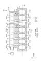
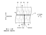
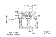
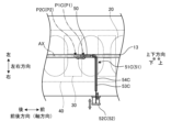
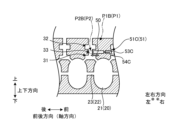
図1は、本実施形態に係る加速空洞100の一例を示す平面図である。図2は、図1におけるA-A断面に沿った構成を示す図である。なお、図2では、断面ではないが分割面12にハッチングを付した状態で示している。図3は、図2におけるB-B断面に沿った構成を示す図である。 Figure 1 is a plan view showing an example of an acceleration cavity 100 according to this embodiment. Figure 2 is a diagram showing the configuration along the A-A cross section in Figure 1. Note that in Figure 2, although it is not a cross section, the dividing surface 12 is shown with hatching. Figure 3 is a diagram showing the configuration along the B-B cross section in Figure 2.

図1から図3に示す加速空洞100は、高周波入力部WIから高周波が入力されることで内部に加速電界を発生させ、線源BSから出射される電子等の荷電粒子Mを加速させる。加速空洞100及び線源BSを用いて、加速器ACが構成される。加速器ACは、例えば高エネルギー物理学実験や放射光施設などの学術分野、放射線治療又は検査などの医療分野、非破壊検査などの工業分野等の各種分野において用いられる。なお、以下の説明において、加速空洞100における方向のうち中心軸AXの軸線方向を説明する場合、線源BS側(荷電粒子Mが入射する側)を入射側又は後方と表記し、入射側の反対側(荷電粒子が出射する側)を出射側又は前方と表記する。また、加速空洞100を施設等に配置した状態において、鉛直方向を上下方向と表記し、中心軸AXの後方から前方を見た場合に上下方向に直交する方向を左右方向と表記する。 The acceleration cavity 100 shown in Figures 1 to 3 generates an acceleration electric field inside by inputting high frequency waves from the high frequency input unit WI, and accelerates charged particles M such as electrons emitted from the radiation source BS. The acceleration cavity 100 and the radiation source BS are used to form an accelerator AC. The accelerator AC is used in various fields, such as academic fields such as high energy physics experiments and synchrotron radiation facilities, medical fields such as radiation therapy or inspection, and industrial fields such as non-destructive inspection. In the following description, when describing the axial direction of the central axis AX among the directions in the acceleration cavity 100, the radiation source BS side (the side where the charged particles M are incident) is referred to as the incident side or rear, and the side opposite the incident side (the side where the charged particles are emitted) is referred to as the exit side or front. In addition, when the acceleration cavity 100 is placed in a facility, the vertical direction is referred to as the up-down direction, and the direction perpendicular to the up-down direction when looking forward from the rear of the central axis AX is referred to as the left-right direction.

図1から図3に示すように、本実施形態に係る加速空洞100は、筐体10と、セル部20と、結合空洞30と、真空マニホールド40と、スイッチ部材50とを備える。 As shown in Figures 1 to 3, the acceleration cavity 100 according to this embodiment includes a housing 10, a cell section 20, a coupling cavity 30, a vacuum manifold 40, and a switch member 50.

筐体10は、導電性を有する筒形状である。筐体10は、複数の分割部材11を接合した状態で形成される。分割部材11は、中心軸AXに沿った平面状の分割面12を有する。各分割部材11は、分割面12同士が対向した状態で接合される。各分割部材11は、対向する分割面12同士の間に隙間13を空けた状態で設けられる。本実施形態では、筐体10が水平面に直交しかつ中心軸AXを通る平面に沿って当該中心軸AXの左右方向に分割された構成を例に挙げて説明する。筐体10の分割数は、2つに限定されず、3つ以上であってもよい。分割部材11は、全体的に互いに対向する部分が丸みを帯びた形状を有している。このため、電圧が局所的に印加されることが抑制される。 The housing 10 has a cylindrical shape having electrical conductivity. The housing 10 is formed by joining a plurality of divided members 11. The divided members 11 have planar dividing surfaces 12 along the central axis AX. The divided members 11 are joined with the dividing surfaces 12 facing each other. The divided members 11 are provided with a gap 13 between the divided surfaces 12 facing each other. In this embodiment, an example is described in which the housing 10 is divided in the left-right direction of the central axis AX along a plane perpendicular to the horizontal plane and passing through the central axis AX. The number of divisions of the housing 10 is not limited to two, and may be three or more. The divided members 11 have a shape in which the parts facing each other are generally rounded. This suppresses localized application of voltage.

セル部20は、筐体10の内部に形成される。セル部20は、筐体10の中心軸AXの軸線方向に並んだ状態で配置される。セル部20は、荷電粒子を通過させる連通部22により互いに連通される。連通部22は、中心軸AXに沿って形成される。セル部20は、高周波により荷電粒子を加速させる。 The cell units 20 are formed inside the housing 10. The cell units 20 are arranged side by side in the axial direction of the central axis AX of the housing 10. The cell units 20 are connected to each other by communication units 22 that allow charged particles to pass through. The communication units 22 are formed along the central axis AX. The cell units 20 accelerate the charged particles by high frequency waves.

結合空洞30は、隣り合うセル部20同士の間を接続する。結合空洞30は、隣り合うセル部20の間で高周波を伝搬させる。結合空洞30は、荷電粒子の加速に寄与しない箇所に配置される。結合空洞30は、セル部20に対して中心軸AXに直交する方向のうち同一方向の外側に配置される。本実施形態において、全ての結合空洞30は、中心軸AXを基準としてセル部20に対して上方に配置される。結合空洞30は、セル部20に接続される第1空間部31と、第1空間部31に対して中心軸AXに対して径方向の外側に離れた位置に配置される第2空間部32と、第1空間部31と第2空間部32とを径方向に接続する接続部33とを有する。第1空間部31、第2空間部32及び接続部33は、例えば上下方向に沿って延びる軸を中心とした円柱状である。第1空間部31、第2空間部32及び接続部33は、四角柱状等であってもよい。接続部33は、第1空間部31及び第2空間部32に比べて、上下方向を中心とした径が小さくなっている。 The coupling cavity 30 connects adjacent cell parts 20. The coupling cavity 30 propagates high frequency waves between adjacent cell parts 20. The coupling cavity 30 is arranged in a location that does not contribute to the acceleration of charged particles. The coupling cavity 30 is arranged on the outside of the same direction perpendicular to the central axis AX with respect to the cell part 20. In this embodiment, all the coupling cavities 30 are arranged above the cell part 20 with respect to the central axis AX as a reference. The coupling cavity 30 has a first space part 31 connected to the cell part 20, a second space part 32 arranged at a position radially outwardly away from the central axis AX with respect to the first space part 31, and a connection part 33 that connects the first space part 31 and the second space part 32 in the radial direction. The first space part 31, the second space part 32, and the connection part 33 are cylindrical with the center being an axis extending along the vertical direction, for example. The first space 31, the second space 32, and the connection portion 33 may be in the shape of a rectangular prism, etc. The connection portion 33 has a smaller diameter centered in the vertical direction than the first space 31 and the second space 32.

真空マニホールド40は、複数のセル部20を真空排気する際の負圧を形成する部分である。真空マニホールド40は、配管43を介して真空ポンプ等の真空形成部42に接続される。本実施形態において、真空マニホールド40は、例えば筐体10の内部に設けられる。真空マニホールド40は、1つの空間として形成され、各結合空洞30の上方に配置される。真空マニホールド40は、分割部材11同士の隙間13を介して複数のセル部20に接続される。各セル部20は、1つの真空マニホールド40に接続される。また、本実施形態において、真空マニホールド40は、連通部45を介して結合空洞30に連通される。したがって、真空マニホールド40は、各結合空洞30の第2空間部32に接続され、当該第2空間部32から結合空洞30を介して複数のセル部20に接続される。この構成により、真空マニホールド40と複数のセル部20との間が確実に接続される。 The vacuum manifold 40 is a part that forms a negative pressure when evacuating the multiple cell parts 20. The vacuum manifold 40 is connected to a vacuum forming part 42 such as a vacuum pump via a pipe 43. In this embodiment, the vacuum manifold 40 is provided, for example, inside the housing 10. The vacuum manifold 40 is formed as one space and is arranged above each coupling cavity 30. The vacuum manifold 40 is connected to the multiple cell parts 20 via the gaps 13 between the dividing members 11. Each cell part 20 is connected to one vacuum manifold 40. In this embodiment, the vacuum manifold 40 is connected to the coupling cavity 30 via the communication part 45. Therefore, the vacuum manifold 40 is connected to the second space part 32 of each coupling cavity 30, and is connected to the multiple cell parts 20 from the second space part 32 via the coupling cavity 30. This configuration ensures a connection between the vacuum manifold 40 and the multiple cell parts 20.

図2に示すように、筐体10において、各分割部材11の分割面12には、セル部20及び連通部22の一部を構成する単位セル部21及び単位連通部23と、結合空洞30の一部を構成する単位結合空洞35と、真空マニホールド40の一部を構成する単位マニホールド41とが形成される。 As shown in FIG. 2, in the housing 10, the dividing surface 12 of each divided member 11 is formed with a unit cell portion 21 and a unit communication portion 23 which constitute a part of the cell portion 20 and the communication portion 22, a unit combined cavity 35 which constitutes a part of the combined cavity 30, and a unit manifold 41 which constitutes a part of the vacuum manifold 40.

セル部20は、分割部材11のそれぞれに設けられる単位セル部21同士を組み合わせることで構成される。連通部22は、分割部材11のそれぞれに設けられる単位連通部24同士を組み合わせることで構成される。結合空洞30は、分割部材11のそれぞれに設けられる単位結合空洞35同士を組み合わせることで構成される。真空マニホールド40は、各分割部材11に形成される単位マニホールド41同士が組み合わされることで構成される。 The cell section 20 is formed by combining unit cell sections 21 provided in each divided member 11. The communication section 22 is formed by combining unit communication sections 24 provided in each divided member 11. The coupling cavity 30 is formed by combining unit coupling cavities 35 provided in each divided member 11. The vacuum manifold 40 is formed by combining unit manifolds 41 formed in each divided member 11.

スイッチ部材50は、筐体10の隙間13に配置される。スイッチ部材50は、中心軸AXを通る平面に沿って隙間13を移動可能である。本実施形態において、スイッチ部材50は、中心軸AXを通り左右方向に直交する平面に沿って隙間13を移動可能である。スイッチ部材50は、移動により荷電粒子を加速させる電界の大きさを切り替える。スイッチ部材50により電界の大きさを切り替えることで、荷電粒子のエネルギーの大きさを切り替えることができる。 The switch member 50 is disposed in the gap 13 of the housing 10. The switch member 50 is movable in the gap 13 along a plane passing through the central axis AX. In this embodiment, the switch member 50 is movable in the gap 13 along a plane passing through the central axis AX and perpendicular to the left-right direction. The switch member 50 switches the magnitude of the electric field that accelerates the charged particles as it moves. By switching the magnitude of the electric field with the switch member 50, the magnitude of the energy of the charged particles can be switched.

スイッチ部材50は、例えば金属等の導体を用いて形成される。スイッチ部材50は、例えば隙間13の寸法よりも厚さが薄い板状である。スイッチ部材50は、結合空洞30に出没するように配置される。スイッチ部材50は、結合空洞30の内部に入り込んだ状態で配置される場合に、当該結合空洞30の電磁場を遮断することが可能となる。スイッチ部材50は、結合空洞30から退避した退避位置P1と、結合空洞30の内部に入り込んだ遮断位置P2との間を移動可能である。本実施形態において、遮断位置P2は、結合空洞30の接続部33に入り込んだ位置に設定することができる。 The switch member 50 is formed using a conductor such as metal. The switch member 50 is, for example, a plate-like member with a thickness thinner than the dimension of the gap 13. The switch member 50 is arranged so as to appear and disappear into the coupling cavity 30. When the switch member 50 is arranged in a state in which it is inserted inside the coupling cavity 30, it is possible to block the electromagnetic field of the coupling cavity 30. The switch member 50 is movable between a retracted position P1 in which it is retracted from the coupling cavity 30, and a blocking position P2 in which it is inserted inside the coupling cavity 30. In this embodiment, the blocking position P2 can be set to a position in which it is inserted into the connection portion 33 of the coupling cavity 30.

スイッチ部材50は、伝達機構51に連結される。伝達機構51は、筐体10の外部に接続される。伝達機構51は、筐体10の外部で発生する駆動力をスイッチ部材50に伝達する。スイッチ部材50に伝達させるための駆動力は、例えば作業者が手動で発生させてもよいし、モータ等の駆動源により発生させてもよい。 The switch member 50 is connected to a transmission mechanism 51. The transmission mechanism 51 is connected to the outside of the housing 10. The transmission mechanism 51 transmits a driving force generated outside the housing 10 to the switch member 50. The driving force to be transmitted to the switch member 50 may be generated, for example, manually by an operator, or may be generated by a driving source such as a motor.

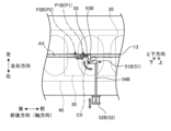
図4から図9は、スイッチ部材50を移動させる構成の例を示す図である。図4、図6及び図8は平面図である。図5、図7及び図9は図1のA-A断面に沿った構成を示す図である。 Figures 4 to 9 are diagrams showing examples of configurations for moving the switch member 50. Figures 4, 6 and 8 are plan views. Figures 5, 7 and 9 are diagrams showing configurations along the A-A cross section of Figure 1.

図4及び図5に示す例では、中心軸AXに直交する回動軸BXを中心として、スイッチ部材50を回動させる構成である。回動軸BXは、左右方向に沿った方向に設定される。この例において、伝達機構51Aは、棒状に形成され、スイッチ部材50から回動軸BXに沿って筐体10を貫通して当該筐体10の外部に延びている。このように、伝達機構51Aは、中心軸AXに沿った平面に対して垂直な方向に延在する。なお、伝達機構51Aが筐体10を貫通する部分において、筐体10の内部の真空状態を維持するように、シール機構を有するベアリング等が設けられてもよい。また、スイッチ部材50を磁気カップリング等により非接触で筐体10の外部から回転させる構成であってもよい。筐体10の外部には、伝達機構51Aを回動させる回動部52Aが設けられる。回動部52Aは、例えばモータ装置である。なお、回動部52Aとして、作業者が手動で伝達機構51Aを回動させる構成であってもよい。 4 and 5, the switch member 50 is rotated around a rotation axis BX perpendicular to the central axis AX. The rotation axis BX is set in the left-right direction. In this example, the transmission mechanism 51A is formed in a rod shape and extends from the switch member 50 along the rotation axis BX through the housing 10 to the outside of the housing 10. In this way, the transmission mechanism 51A extends in a direction perpendicular to the plane along the central axis AX. In addition, a bearing having a sealing mechanism may be provided at the portion where the transmission mechanism 51A penetrates the housing 10 so as to maintain a vacuum state inside the housing 10. In addition, the switch member 50 may be rotated from the outside of the housing 10 in a non-contact manner by a magnetic coupling or the like. A rotating unit 52A that rotates the transmission mechanism 51A is provided outside the housing 10. The rotating unit 52A is, for example, a motor device. In addition, the rotating unit 52A may be configured so that an operator manually rotates the transmission mechanism 51A.

回動部52Aにより伝達機構51Aを回動させることにより、スイッチ部材50が回動軸BXを中心として回動する。スイッチ部材50は、結合空洞30から退避した退避位置P1Aと、結合空洞30に入り込んだ遮断位置P2Bとの間を、中心軸AXを含む平面に沿って回動する。スイッチ部材50の回動範囲については、エンコーダ等を設けて回動部52Aによる回動量を調節してもよいし、ストッパ等の物理的な機構により調整してもよい。 By rotating the transmission mechanism 51A with the rotating part 52A, the switch member 50 rotates around the rotation axis BX. The switch member 50 rotates along a plane including the central axis AX between a retracted position P1A where it is retracted from the coupling cavity 30 and a blocking position P2B where it is inserted into the coupling cavity 30. The rotation range of the switch member 50 may be adjusted by providing an encoder or the like to adjust the amount of rotation by the rotating part 52A, or may be adjusted by a physical mechanism such as a stopper.

図6及び図7に示す例では、スイッチ部材50を中心軸AXに沿ってスライドさせる構成である。この例において、伝達機構51Bは、回動部材53Bと、棒状部材54Bと、支持部材55Bとを有する。回動部材53Bは、基端部から2方向(ここでは、例えば左右方向、前後方向)に延び出したL字状に形成される。回動部材53Bは、基端部を通り上下方向に沿った回動軸CXを中心として回動する。回動部材53Bは、例えば左右方向に延び出した部分の先端がスイッチ部材50に連結される。回動部材53Bは、例えば前後方向に延び出した部分の先端が棒状部材54Bに連結される。棒状部材54Bは、左右方向に沿って筐体10の外部に延びている。このように、伝達機構51Bは、中心軸AXに沿った平面に対して垂直な方向に延在する。 6 and 7, the switch member 50 is configured to slide along the central axis AX. In this example, the transmission mechanism 51B has a rotating member 53B, a rod-shaped member 54B, and a support member 55B. The rotating member 53B is formed in an L-shape extending from the base end in two directions (here, for example, the left-right direction and the front-back direction). The rotating member 53B rotates around a rotation axis CX that passes through the base end and runs in the up-down direction. The tip of the rotating member 53B that extends in the left-right direction is connected to the switch member 50. The tip of the rotating member 53B that extends in the front-back direction is connected to the rod-shaped member 54B. The rod-shaped member 54B extends outside the housing 10 along the left-right direction. In this way, the transmission mechanism 51B extends in a direction perpendicular to a plane along the central axis AX.

筐体10の外部には、棒状部材54Bを左右方向に移動させる駆動部52Bが設けられる。駆動部52Bは、例えばベローズ機構である。ベローズを伸縮させることにより、棒状部材54Bを左右方向に移動させることができる。なお、駆動部52Bとしては、ベローズ機構に代えて、ボールねじ機構、エアシリンダ機構等の他の駆動機構が用いられてもよい。 A drive unit 52B is provided on the outside of the housing 10 to move the rod-shaped member 54B in the left-right direction. The drive unit 52B is, for example, a bellows mechanism. The rod-shaped member 54B can be moved in the left-right direction by expanding and contracting the bellows. Note that, instead of the bellows mechanism, other drive mechanisms such as a ball screw mechanism or an air cylinder mechanism may be used as the drive unit 52B.

駆動部52Bにおいてベローズを伸ばすことで、棒状部材54Bが右方に移動する。棒状部材54Bが右方に移動すると、回動部材53Bが上方から見て回動軸CXを中心として時計回りに回動する。この場合、基端部から左右方向に延び出した部分の先端が前方に移動する。このため、スイッチ部材50が前方に移動する。 By stretching the bellows in the drive unit 52B, the rod-shaped member 54B moves to the right. When the rod-shaped member 54B moves to the right, the rotating member 53B rotates clockwise around the rotation axis CX when viewed from above. In this case, the tip of the part that extends left and right from the base end moves forward. As a result, the switch member 50 moves forward.

駆動部52Bにおいてベローズを縮ませることで、棒状部材54Bが左方に移動する。棒状部材54Bが左方に移動すると、回動部材53Bが上方から見て回動軸CXを中心として反時計回りに回動する。この場合、基端部から左右方向に延び出した部分の先端が後方に移動する。このため、スイッチ部材50が後方に移動する。 By contracting the bellows in the drive unit 52B, the rod-shaped member 54B moves to the left. When the rod-shaped member 54B moves to the left, the rotating member 53B rotates counterclockwise around the rotation axis CX when viewed from above. In this case, the tip of the part that extends left and right from the base end moves rearward. As a result, the switch member 50 moves rearward.

このように、伝達機構51B及び駆動部52Bにより、スイッチ部材50を前後方向にスライド移動させることができる。図6及び図7に示す例では、スイッチ部材50が前方に移動した位置を退避位置P1Bとし、スイッチ部材50が後方に移動した位置を遮断位置P2Bとしている。なお、スイッチ部材50が前方に移動した位置を遮断位置P2Bとし、スイッチ部材50が後方に移動した位置を退避位置P1Bとしてもよい。 In this way, the switch member 50 can be slid forward and backward by the transmission mechanism 51B and the drive unit 52B. In the example shown in Figures 6 and 7, the position to which the switch member 50 has moved forward is the retracted position P1B, and the position to which the switch member 50 has moved rearward is the blocking position P2B. Note that the position to which the switch member 50 has moved forward may be the blocking position P2B, and the position to which the switch member 50 has moved rearward may be the retracted position P1B.

図8及び図9に示す例では、スイッチ部材50を中心軸AXに沿ってスライドさせる構成である。この例において、伝達機構51Cは、線状部材53Cと、案内部材54Cとを有する。線状部材53Cは、一端(スイッチ側端部)がスイッチ部材50に連結される。線状部材53Cは、例えばワイヤ等のように長手方向に剛性を有し、かつ長手方向に直交する方向には変形可能な部材を用いることができる。線状部材53Cは、例えばスイッチ部材50から前方に引き出され、案内部材54Cにより左方に湾曲され、先端が筐体10の外部に延びた状態で配置される。案内部材54Cは、例えばチューブ等の管状部材を用いることができる。線状部材53Cは、案内部材54Cの内部に通された状態で設けられる。このように、伝達機構51Cは、中心軸AXに沿った平面に対して垂直な方向に延在する。 8 and 9, the switch member 50 is configured to slide along the central axis AX. In this example, the transmission mechanism 51C has a linear member 53C and a guide member 54C. One end (switch side end) of the linear member 53C is connected to the switch member 50. The linear member 53C may be a member that has rigidity in the longitudinal direction and is deformable in a direction perpendicular to the longitudinal direction, such as a wire. The linear member 53C is, for example, drawn forward from the switch member 50, curved to the left by the guide member 54C, and disposed with its tip extending outside the housing 10. The guide member 54C may be a tubular member such as a tube. The linear member 53C is provided in a state of being passed through the inside of the guide member 54C. In this way, the transmission mechanism 51C extends in a direction perpendicular to a plane along the central axis AX.

筐体10の外部には、線状部材53Cを左右方向に移動させる駆動部52Cが設けられる。駆動部52Cは、線状部材53Cの他端(駆動側端部)に連結される。駆動部52Cは、上記した駆動部52Bと同様に、例えばベローズ機構である。ベローズを伸縮させることにより、線状部材53Cを左右方向に移動させることができる。なお、駆動部52Cとしては、ベローズ機構に代えて、ボールねじ機構、エアシリンダ機構等の他の駆動機構が用いられてもよい。 A drive unit 52C for moving the linear member 53C in the left-right direction is provided outside the housing 10. The drive unit 52C is connected to the other end (the drive side end) of the linear member 53C. The drive unit 52C is, for example, a bellows mechanism, similar to the drive unit 52B described above. The linear member 53C can be moved in the left-right direction by expanding and contracting the bellows. Note that instead of the bellows mechanism, other drive mechanisms such as a ball screw mechanism or an air cylinder mechanism may be used as the drive unit 52C.

駆動部52Cにおいてベローズを伸ばすことで、線状部材53Cの駆動側端部が右方に引っ張られる。線状部材53Cは、案内部材54Cにより湾曲されてスイッチ側端部が前後方向に沿って配置された状態である。したがって、線状部材53Cは、駆動側端部が右方に引っ張られることにより、スイッチ側端部が前方に移動する。これにより、スイッチ部材50が前方に移動する。 By stretching the bellows in the drive section 52C, the drive side end of the linear member 53C is pulled to the right. The linear member 53C is curved by the guide member 54C so that the switch side end is arranged along the front-to-rear direction. Therefore, when the drive side end of the linear member 53C is pulled to the right, the switch side end moves forward. This causes the switch member 50 to move forward.

駆動部52Cにおいてベローズを縮ませることで、線状部材53Cの駆動側端部が左方に押される。線状部材53Cは、案内部材54Cにより湾曲されてスイッチ側端部が前後方向に沿って配置された状態である。したがって、線状部材53Cは、駆動側端部が左方に押されることにより、スイッチ側端部が後方に移動する。これにより、スイッチ部材50が後方に移動する。 By compressing the bellows in the drive section 52C, the drive side end of the linear member 53C is pushed to the left. The linear member 53C is curved by the guide member 54C so that the switch side end is arranged along the front-to-rear direction. Therefore, when the drive side end of the linear member 53C is pushed to the left, the switch side end moves rearward. This causes the switch member 50 to move rearward.

このように、伝達機構51C及び駆動部52Cにより、スイッチ部材50を前後方向にスライド移動させることができる。図8及び図9に示す例では、図6及び図7に示す例と同様、スイッチ部材50が前方に移動した位置を退避位置P1Cとし、スイッチ部材50が後方に移動した位置を遮断位置P2Cとしている。なお、スイッチ部材50が前方に移動した位置を遮断位置P2Cとし、スイッチ部材50が後方に移動した位置を退避位置P1Cとしてもよい。 In this way, the switch member 50 can be slid forward and backward by the transmission mechanism 51C and the drive unit 52C. In the example shown in Figures 8 and 9, similar to the example shown in Figures 6 and 7, the position to which the switch member 50 has moved forward is the retracted position P1C, and the position to which the switch member 50 has moved rearward is the blocking position P2C. Note that the position to which the switch member 50 has moved forward may be the blocking position P2C, and the position to which the switch member 50 has moved rearward may be the retracted position P1C.

図10は、加速空洞100の他の例を示す図である。図10に示すように、隙間13においてスイッチ部材50が配置される部分には、当該スイッチ部材50の可動範囲の少なくとも一部に移動用隙間14が設けられてもよい。移動用隙間14は、分割面12同士の距離が隙間13よりも大きくなっている部分である。移動用隙間14が設けられることにより、スイッチ部材50が筐体10の分割面12に干渉することを抑制できる。 Figure 10 is a diagram showing another example of an acceleration cavity 100. As shown in Figure 10, a movement gap 14 may be provided in at least a part of the movable range of the switch member 50 in the portion of the gap 13 where the switch member 50 is disposed. The movement gap 14 is a portion where the distance between the dividing surfaces 12 is greater than the gap 13. By providing the movement gap 14, it is possible to prevent the switch member 50 from interfering with the dividing surface 12 of the housing 10.

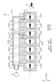
図11及び図12は、加速空洞100の使用態様の一例を示す図である。図11に示すように、スイッチ部材50を退避位置P1に配置させた場合、高周波入力部WIから入力される高周波は、全てのセル部20に伝搬される。このため、線源BSから出射されて加速空洞100の内部に入射した荷電粒子Mは、通過する全てのセル部20で加速されて出射される。 Figures 11 and 12 are diagrams showing an example of how the acceleration cavity 100 is used. As shown in Figure 11, when the switch member 50 is placed in the retracted position P1, the high frequency input from the high frequency input unit WI is propagated to all the cell units 20. Therefore, the charged particles M emitted from the radiation source BS and entering the inside of the acceleration cavity 100 are accelerated and emitted by all the cell units 20 that they pass through.

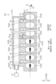
これに対して、図12に示すように、スイッチ部材50を遮断位置P2に配置させた場合、高周波入力部WIから入力される高周波は、遮断位置P2において遮断される。加速空洞100において、遮断位置P2から先のセル部20については、高周波が伝搬されない。したがって、線源BSから出射されて加速空洞100の内部に入射した荷電粒子Mは、通過するセル部20のうち高周波が伝搬されたセル部20において加速され、高周波が伝搬されないセル部20においては加速されずに出射される。この場合、荷電粒子Mのエネルギーは、スイッチ部材50が退避位置P1に配置された場合に比べて小さくなる。このように、荷電粒子Mのエネルギーを切り替えることで、加速空洞100を検査装置、治療装置等に幅広く用いることができる。 In contrast, as shown in FIG. 12, when the switch member 50 is placed in the cut-off position P2, the high frequency input from the high frequency input section WI is cut off at the cut-off position P2. In the acceleration cavity 100, the high frequency is not propagated to the cell section 20 beyond the cut-off position P2. Therefore, the charged particle M emitted from the radiation source BS and entering the inside of the acceleration cavity 100 is accelerated in the cell section 20 through which the high frequency is propagated among the cell sections 20 through which it passes, and is emitted without being accelerated from the cell section 20 through which the high frequency is not propagated. In this case, the energy of the charged particle M is smaller than when the switch member 50 is placed in the retract position P1. In this way, by switching the energy of the charged particle M, the acceleration cavity 100 can be widely used for examination devices, treatment devices, etc.

以上のように、本開示の第1態様に従えば、導電性を有する筒形状であり、中心軸AXに沿った平面で複数に分割された分割部材11を平面に沿った分割面12同士が隙間13を空けて対向した状態で設けられる筐体10と、筐体10の内部に当該筐体10の中心軸AXの軸線方向に並んだ状態で配置され、荷電粒子を通過可能な連通部22により互いに連通された複数のセル部20と、筐体10の隙間13に配置され、中心軸AXを通る平面に沿って隙間13を移動可能であり、移動により荷電粒子を加速させる電界の大きさを切り替えるスイッチ部材50とを備える加速空洞が提供される。 As described above, according to the first aspect of the present disclosure, an acceleration cavity is provided that includes a cylindrical conductive housing 10 in which a dividing member 11 is divided into a plurality of parts on a plane along the central axis AX, with the dividing surfaces 12 along the plane facing each other with a gap 13 therebetween, a plurality of cell sections 20 arranged inside the housing 10 in a lined-up state along the axial direction of the central axis AX of the housing 10 and connected to each other by communication sections 22 that allow charged particles to pass through, and a switch member 50 arranged in the gap 13 of the housing 10 and movable through the gap 13 along a plane passing through the central axis AX, and which switches the magnitude of the electric field that accelerates the charged particles as it moves.

この構成によれば、複数に分割された分割部材11の分割面12同士が隙間13を空けて対向した状態で筐体10が設けられる構成において、隙間13を利用してスイッチ部材50を移動させることで、複雑な機構を用いることなく荷電粒子Mのエネルギーを容易に切り替えることが可能となる。 With this configuration, in a configuration in which the divided surfaces 12 of the divided members 11, which are divided into multiple parts, face each other with a gap 13 between them, the housing 10 is provided, and by using the gap 13 to move the switch member 50, it is possible to easily switch the energy of the charged particles M without using a complex mechanism.

本開示の第2態様に係る加速空洞では、第1態様において、筐体10の内部に設けられ、隣り合うセル部20同士の間を接続する結合空洞30を更に備え、スイッチ部材50は、結合空洞30に出没するように配置される。 In the acceleration cavity according to the second aspect of the present disclosure, in the first aspect, a coupling cavity 30 is provided inside the housing 10 and connects adjacent cell units 20, and the switch member 50 is arranged to appear and disappear in the coupling cavity 30.

この構成によれば、スイッチ部材50が結合空洞に出没するように配置されるため、高周波の伝搬及び遮断を効率的に切り替えることができる。 With this configuration, the switch member 50 is positioned so that it appears and disappears from the coupling cavity, allowing efficient switching between transmitting and blocking high frequency waves.

本開示の第3態様に係る加速空洞では、第2態様において、全ての結合空洞30は、セル部20に対して中心軸AXに直交する方向について同じ側に配置される。 In the acceleration cavity according to the third aspect of the present disclosure, in the second aspect, all of the coupling cavities 30 are arranged on the same side of the cell section 20 in a direction perpendicular to the central axis AX.

この構成によれば、結合空洞30をセル部20に対して中心軸AXに直交する方向の同じ側に寄せることにより、中心軸AXに直交する方向の電場分布の中心を中心軸AXに合わせることができる。このため、荷電粒子のビームの偏りを抑制することができる。 With this configuration, by moving the coupling cavity 30 to the same side of the cell section 20 in the direction perpendicular to the central axis AX, the center of the electric field distribution in the direction perpendicular to the central axis AX can be aligned with the central axis AX. This makes it possible to suppress bias in the charged particle beam.

本開示の第4態様に係る加速空洞では、第2態様において、結合空洞30は、セル部20に接続される第1空間部31と、第1空間部31に対して中心軸AXに対して径方向の外側に離れた位置に配置される第2空間部32と、第1空間部31と第2空間部32とを径方向に接続する接続部33とを有し、スイッチ部材50は、接続部33に出没するように配置される。 In the acceleration cavity according to the fourth aspect of the present disclosure, in the second aspect, the coupling cavity 30 has a first space portion 31 connected to the cell portion 20, a second space portion 32 arranged at a position radially outwardly spaced from the first space portion 31 with respect to the central axis AX, and a connection portion 33 that radially connects the first space portion 31 and the second space portion 32, and the switch member 50 is arranged so as to appear and disappear from the connection portion 33.

この構成によれば、スイッチ部材50が結合空洞30の接続部33に出没するように配置されるため、高周波の伝搬及び遮断を効率的に切り替えることができる。 With this configuration, the switch member 50 is positioned so that it appears and disappears from the connection portion 33 of the coupling cavity 30, allowing efficient switching between transmitting and blocking high frequency waves.

本開示の第5態様に係る加速空洞では、第1態様において、結合空洞30は、第2空間部32が真空マニホールド40に接続される。 In the acceleration cavity according to the fifth aspect of the present disclosure, in the first aspect, the coupling cavity 30 has the second space portion 32 connected to the vacuum manifold 40.

この構成によれば、真空マニホールド40が結合空洞30を介してセル部20に接続されるため、真空マニホールド40によりセル部20をより確実に真空排気することができる。 With this configuration, the vacuum manifold 40 is connected to the cell portion 20 via the coupling cavity 30, so that the vacuum manifold 40 can more reliably evacuate the cell portion 20 to a vacuum.

本開示の第6態様に係る加速空洞では、第1態様から第5態様のいずれかにおいて、筐体10は、スイッチ部材50の可動範囲の少なくとも一部に、分割面12同士の距離が隙間13よりも大きくなる移動用隙間14を有する。 In the acceleration cavity according to the sixth aspect of the present disclosure, in any of the first to fifth aspects, the housing 10 has a movement gap 14 in at least a portion of the movable range of the switch member 50, in which the distance between the dividing surfaces 12 is greater than the gap 13.

この構成によれば、移動用隙間14が設けられることにより、スイッチ部材50が筐体10の分割面12に干渉することを抑制できる。 With this configuration, the provision of the movement gap 14 can prevent the switch member 50 from interfering with the dividing surface 12 of the housing 10.

本開示の第7態様に係る加速空洞では、第1態様から第6態様のいずれかにおいて、筐体10の外部で発生する駆動力をスイッチ部材50に伝達する伝達機構51を更に備える。 In the acceleration cavity according to the seventh aspect of the present disclosure, in any of the first to sixth aspects, a transmission mechanism 51 is further provided that transmits a driving force generated outside the housing 10 to the switch member 50.

この構成によれば、伝達機構51が設けられることにより、筐体10の外部からスイッチ部材50を移動させることができる。 With this configuration, the transmission mechanism 51 is provided, so that the switch member 50 can be moved from outside the housing 10.

本開示の第8態様に係る加速空洞では、第7態様において、伝達機構51は、平面に対して垂直な方向に延在する。 In the acceleration cavity according to the eighth aspect of the present disclosure, in the seventh aspect, the transmission mechanism 51 extends in a direction perpendicular to the plane.

この構成によれば、伝達機構51が平面に対して垂直な方向に延在するため、例えばスイッチ部材50を回動させる場合、スライドさせる場合のいずれの場合においても駆動力を適切に伝達することができる。 With this configuration, the transmission mechanism 51 extends in a direction perpendicular to the plane, so that the driving force can be appropriately transmitted whether the switch member 50 is rotated or slid.

本開示の第9態様に係る加速空洞では、第1態様から第7態様のいずれかにおいて、伝達機構51は、スイッチ部材50が中心軸AXに直交する方向に沿った回動軸BXを中心として回動するように駆動力を伝達する。 In the acceleration cavity according to the ninth aspect of the present disclosure, in any of the first to seventh aspects, the transmission mechanism 51 transmits a driving force so that the switch member 50 rotates about a rotation axis BX that is aligned in a direction perpendicular to the central axis AX.

この構成によれば、伝達機構51により、中心軸AXに直交する方向に沿った回動軸BXを中心として回動するようにスイッチ部材50を移動させることができる。 With this configuration, the transmission mechanism 51 can move the switch member 50 so that it rotates around the rotation axis BX that is aligned in a direction perpendicular to the central axis AX.

本開示の第10態様に係る加速空洞では、第1態様から第7態様のいずれかにおいて、伝達機構51は、スイッチ部材50が中心軸AXに沿った方向にスライドするように駆動力を伝達する。 In the acceleration cavity according to the tenth aspect of the present disclosure, in any of the first to seventh aspects, the transmission mechanism 51 transmits the driving force so that the switch member 50 slides in a direction along the central axis AX.

この構成によれば、伝達機構51により、中心軸AXに直交する方向に沿った方向にスライドするようにスイッチ部材50を移動させることができる。 With this configuration, the transmission mechanism 51 can move the switch member 50 so that it slides in a direction perpendicular to the central axis AX.

上記した実施形態では、スイッチ部材50が1つ設けられた構成を例に挙げて説明したが、この構成に限定されない。スイッチ部材50は、複数設けられてもよい。この場合、複数のスイッチ部材50が個別に移動可能であり、異なる結合空洞30に出没するように設けることができる。 In the above embodiment, a configuration in which one switch member 50 is provided has been described as an example, but this configuration is not limited to this. A plurality of switch members 50 may be provided. In this case, the plurality of switch members 50 can be individually movable and can be provided so as to appear and disappear into different coupling cavities 30.

10 筐体
11 分割部材
12 分割面
13 隙間
14 移動用隙間
20 セル部
21 単位セル部
22,45 連通部
23,24 単位連通部
30 結合空洞
31 第1空間部
32 第2空間部
33 接続部
35 単位結合空洞
40 真空マニホールド
41 単位マニホールド
42 真空形成部
43 配管
50 スイッチ部材
51,51A,51B,51C 伝達機構
52A 回動部
52B,52C 駆動部
53B 回動部材
53C 線状部材
54B 棒状部材
54C 案内部材
55B 支持部材
100 加速空洞
AC 加速器
AX 中心軸
BS 線源
BX,CX 回動軸
M 荷電粒子
P1,P1A,P1B,P1C 退避位置
P2,P2A,P2B,P2C 遮断位置
WI 高周波入力部
10 Housing 11 Dividing member 12 Dividing surface 13 Gap 14 Movement gap 20 Cell portion 21 Unit cell portion 22, 45 Communication portion 23, 24 Unit communication portion 30 Coupling cavity 31 First space portion 32 Second space portion 33 Connection portion 35 Unit coupling cavity 40 Vacuum manifold 41 Unit manifold 42 Vacuum forming portion 43 Pipe 50 Switch member 51, 51A, 51B, 51C Transmission mechanism 52A Rotating portion 52B, 52C Driving portion 53B Rotating member 53C Linear member 54B Rod-shaped member 54C Guide member 55B Support member 100 Acceleration cavity AC Accelerator AX Central axis BS Radiation source BX, CX Rotation axis M Charged particle P1, P1A, P1B, P1C Retraction position P2, P2A, P2B, P2C Shut-off position WI High Frequency Input Section

Claims (10)

導電性を有する筒形状であり、中心軸に沿った平面で複数に分割された分割部材を前記平面に沿った分割面同士が隙間を空けて対向した状態で設けられる筐体と、
前記筐体の内部に当該筐体の中心軸の軸線方向に並んだ状態で配置され、荷電粒子を通過可能な連通部により互いに連通された複数のセル部と、
前記筐体の前記隙間に配置され、前記平面に沿って前記隙間を移動可能であり、移動により前記荷電粒子を加速させる電界の大きさを切り替えるスイッチ部材と
を備える加速空洞。
a housing having a conductive cylindrical shape, the housing including a divided member divided into a plurality of parts along a plane along a central axis, the divided surfaces along the plane being opposed to each other with a gap therebetween;
a plurality of cell units arranged inside the housing in an axial direction of a central axis of the housing and connected to each other by communication units through which charged particles can pass;
a switch member that is disposed in the gap of the housing, movable in the gap along the plane, and switches the magnitude of an electric field that accelerates the charged particles as the switch member moves.
前記筐体の内部に設けられ、隣り合う前記セル部同士を前記中心軸からオフセットした位置で連通する結合空洞を更に備え、
前記スイッチ部材は、前記結合空洞に出没するように配置される
請求項1に記載の加速空洞。
a coupling cavity provided inside the housing and communicating with adjacent cells at a position offset from the central axis;
The accelerating cavity according to claim 1 , wherein the switch member is arranged to appear and disappear from the coupling cavity.
全ての前記結合空洞は、前記セル部に対して前記中心軸に直交する方向について同じ側に配置される
請求項2に記載の加速空洞。
The acceleration cavity according to claim 2 , wherein all of the coupling cavities are disposed on the same side of the cell portion in a direction perpendicular to the central axis.
前記結合空洞は、前記セル部に接続される第1空間部と、前記第1空間部に対して前記中心軸に対して径方向の外側に離れた位置に配置される第2空間部と、前記第1空間部と前記第2空間部とを前記径方向に接続する接続部とを有し、
前記スイッチ部材は、前記接続部に出没するように配置される
請求項2に記載の加速空洞。
the coupling cavity has a first space portion connected to the cell portion, a second space portion disposed at a position radially outwardly spaced from the first space portion with respect to the central axis, and a connection portion connecting the first space portion and the second space portion in the radial direction,
The acceleration cavity according to claim 2 , wherein the switch member is disposed so as to appear and disappear from the connection portion.
前記隙間を介して複数の前記セル部に接続された真空マニホールドを更に備え、
前記結合空洞は、前記第2空間部が前記真空マニホールドに接続される
請求項4に記載の加速空洞。
a vacuum manifold connected to the plurality of cells via the gap;
The acceleration cavity according to claim 4 , wherein the second space of the coupling cavity is connected to the vacuum manifold.
前記筐体は、前記スイッチ部材の可動範囲の少なくとも一部に、前記分割面同士の距離が前記隙間よりも大きくなる移動用隙間を有する
請求項1に記載の加速空洞。
The acceleration cavity according to claim 1 , wherein the housing has a movement gap in which the distance between the divided surfaces is larger than the gap, in at least a part of a movable range of the switch member.
前記筐体の外部で発生する駆動力を前記スイッチ部材に伝達する伝達機構を更に備える
請求項1に記載の加速空洞。
The acceleration cavity according to claim 1 , further comprising a transmission mechanism that transmits a driving force generated outside the housing to the switch member.
前記伝達機構は、前記平面に対して垂直な方向に延在する
請求項7に記載の加速空洞。
The acceleration cavity according to claim 7 , wherein the transmission mechanism extends in a direction perpendicular to the plane.
前記伝達機構は、前記スイッチ部材が前記中心軸に直交する方向に沿った回動軸を中心として回動するように前記駆動力を伝達する
請求項7に記載の加速空洞。
The acceleration cavity according to claim 7 , wherein the transmission mechanism transmits the driving force such that the switch member rotates about a rotation axis extending in a direction perpendicular to the central axis.
前記伝達機構は、前記スイッチ部材が前記中心軸に沿った方向にスライドするように前記駆動力を伝達する
請求項7に記載の加速空洞。
The acceleration cavity according to claim 7 , wherein the transmission mechanism transmits the driving force so that the switch member slides in a direction along the central axis.
JP2023148359A 2023-09-13 2023-09-13 Accelerating Cavity Pending JP2025041207A (en)

Priority Applications (2)

Application Number Priority Date Filing Date Title
JP2023148359A JP2025041207A (en) 2023-09-13 2023-09-13 Accelerating Cavity
PCT/JP2024/029381 WO2025057665A1 (en) 2023-09-13 2024-08-20 Acceleration cavity

Applications Claiming Priority (1)

Application Number Priority Date Filing Date Title
JP2023148359A JP2025041207A (en) 2023-09-13 2023-09-13 Accelerating Cavity

Publications (2)

Publication Number Publication Date
JP2025041207A true JP2025041207A (en) 2025-03-26
JP2025041207A5 JP2025041207A5 (en) 2026-02-16

Family

ID=95022196

Family Applications (1)

Application Number Title Priority Date Filing Date
JP2023148359A Pending JP2025041207A (en) 2023-09-13 2023-09-13 Accelerating Cavity

Country Status (2)

Country Link
JP (1) JP2025041207A (en)
WO (1) WO2025057665A1 (en)

Family Cites Families (2)

* Cited by examiner, † Cited by third party
Publication number Priority date Publication date Assignee Title
JPH01264200A (en) * 1988-04-13 1989-10-20 Toshiba Corp Standing wave linear accelerator
US7339320B1 (en) * 2003-12-24 2008-03-04 Varian Medical Systems Technologies, Inc. Standing wave particle beam accelerator

Also Published As

Publication number Publication date
WO2025057665A1 (en) 2025-03-20

Similar Documents

Publication Publication Date Title
US7239095B2 (en) Dual-plunger energy switch
CN106999729A (en) Charged Particle Beam Irradiation Device
US9153404B2 (en) Charged particle beam scanning using deformed high gradient insulator
JP2025041207A (en) Accelerating Cavity
US7208890B2 (en) Multi-section particle accelerator with controlled beam current
CN107949899B (en) Ion milling device
WO2007037380A1 (en) Magnetic field control method and magnetic field generation device
JP6771064B2 (en) Processes and devices for generating plasmas energized by microwave energy in the field of electron cyclotron resonance (ECR) to perform surface treatments or coatings of filamentous components.
KR101725849B1 (en) Linear accelerator having a broadband frequency tunable tuner
US10485089B2 (en) Helical permanent magnet structure and undulator using the same
JPWO2019207958A1 (en) Atomic beam generator, joining device, surface modification method and joining method
CN213635562U (en) Permanent magnet device with gradient magnetic field
JP6052792B2 (en) Microwave ion source and operation method thereof
KR102722451B1 (en) Plasma accelerator using e×b force
KR20200075280A (en) A Multipacting Preventive Device for RF Power Coupler
CN217160084U (en) Accelerating tube, accelerator and radiotherapy equipment
JP7780397B2 (en) Accelerating Cavities and Accelerating Cavity Systems
US3278745A (en) Radio-frequency particle separator
KR101645503B1 (en) Ion irradiation device and ion irradiation method
JP4051318B2 (en) Electron beam cooling device
US20250331095A1 (en) Linear accelerator system
EP0238669A1 (en) Electron linear accelerator
JPH0529097A (en) Resonant frequency adjusting device for high frequency electron gun
Nantista et al. Design of a Compact Linac for High Average Power Radiotherapy
JP2024021159A (en) acceleration cavity

Legal Events

Date Code Title Description
A521 Request for written amendment filed

Free format text: JAPANESE INTERMEDIATE CODE: A523

Effective date: 20260205