JP2025036282A - Contactor movable contact assembly and contactor - Google Patents
Contactor movable contact assembly and contactor Download PDFInfo
- Publication number
- JP2025036282A JP2025036282A JP2024146178A JP2024146178A JP2025036282A JP 2025036282 A JP2025036282 A JP 2025036282A JP 2024146178 A JP2024146178 A JP 2024146178A JP 2024146178 A JP2024146178 A JP 2024146178A JP 2025036282 A JP2025036282 A JP 2025036282A
- Authority
- JP
- Japan
- Prior art keywords
- movable contact
- drive shaft
- contactor
- insulator
- contact
- Prior art date
- Legal status (The legal status is an assumption and is not a legal conclusion. Google has not performed a legal analysis and makes no representation as to the accuracy of the status listed.)
- Pending
Links
Images


Classifications
-
- H—ELECTRICITY
- H01—ELECTRIC ELEMENTS
- H01H—ELECTRIC SWITCHES; RELAYS; SELECTORS; EMERGENCY PROTECTIVE DEVICES
- H01H50/00—Details of electromagnetic relays
- H01H50/16—Magnetic circuit arrangements
- H01H50/18—Movable parts of magnetic circuits, e.g. armature
-
- H—ELECTRICITY
- H01—ELECTRIC ELEMENTS
- H01H—ELECTRIC SWITCHES; RELAYS; SELECTORS; EMERGENCY PROTECTIVE DEVICES
- H01H50/00—Details of electromagnetic relays
- H01H50/54—Contact arrangements
- H01H50/541—Auxiliary contact devices
-
- H—ELECTRICITY
- H01—ELECTRIC ELEMENTS
- H01H—ELECTRIC SWITCHES; RELAYS; SELECTORS; EMERGENCY PROTECTIVE DEVICES
- H01H50/00—Details of electromagnetic relays
- H01H50/44—Magnetic coils or windings
-
- H—ELECTRICITY
- H01—ELECTRIC ELEMENTS
- H01H—ELECTRIC SWITCHES; RELAYS; SELECTORS; EMERGENCY PROTECTIVE DEVICES
- H01H50/00—Details of electromagnetic relays
- H01H50/54—Contact arrangements
- H01H50/546—Contact arrangements for contactors having bridging contacts
-
- H—ELECTRICITY
- H01—ELECTRIC ELEMENTS
- H01H—ELECTRIC SWITCHES; RELAYS; SELECTORS; EMERGENCY PROTECTIVE DEVICES
- H01H50/00—Details of electromagnetic relays
- H01H50/54—Contact arrangements
- H01H50/56—Contact spring sets
- H01H50/58—Driving arrangements structurally associated therewith; Mounting of driving arrangements on armature
-
- H—ELECTRICITY
- H01—ELECTRIC ELEMENTS
- H01H—ELECTRIC SWITCHES; RELAYS; SELECTORS; EMERGENCY PROTECTIVE DEVICES
- H01H50/00—Details of electromagnetic relays
- H01H50/02—Bases; Casings; Covers
- H01H50/023—Details concerning sealing, e.g. sealing casing with resin
- H01H2050/025—Details concerning sealing, e.g. sealing casing with resin containing inert or dielectric gasses, e.g. SF6, for arc prevention or arc extinction
Landscapes
- Physics & Mathematics (AREA)
- Electromagnetism (AREA)
- Contacts (AREA)
Abstract
Description
関連出願の相互参照
本出願は、2023年8月31日に中国国家知識産権局に出願された中国特許出願第202322367305.3号の利益を主張し、その開示全体が参照によって本明細書に組み込まれる。
CROSS-REFERENCE TO RELATED APPLICATIONS This application claims the benefit of Chinese Patent Application No. 202322367305.3, filed with the China State Intellectual Property Office on Aug. 31, 2023, the entire disclosure of which is incorporated herein by reference.
本発明は、コンタクタ可動コンタクトアセンブリ、およびコンタクタ可動コンタクトアセンブリを備えるコンタクタに関する。 The present invention relates to a contactor movable contact assembly and a contactor equipped with a contactor movable contact assembly.
従来技術では、コンタクタ可動コンタクトアセンブリは、通常、可動コンタクト、駆動シャフト、ばね部品、上側絶縁リング、および下側絶縁リングを備える。可動コンタクトは、駆動シャフトに軸方向に移動可能に設置される。駆動シャフトは、可動コンタクトを、静止コンタクトから分離される開位置から静止コンタクトと電気的に接触する閉位置まで駆動するために使用される。ばね部品は、可動コンタクトを駆動シャフトに浮動式に支持し、可動コンタクトに所定の接触圧を加えるために使用される。可動コンタクトを駆動シャフトから電気的に分離するために、上側絶縁リングと下側絶縁リングとを互いに組み付けて、可動コンタクトと駆動シャフトとの間にセットする。駆動シャフトは、下側絶縁リングの中心孔を通過し、下側絶縁リングは、駆動シャフトの肩部と接触する。
ばね部品は、下側絶縁リングにはめられる。上側絶縁リングは、可動コンタクトの中央にある貫通孔に挿入され、駆動シャフトは、上側絶縁リングの中心孔を通過する。
In the prior art, a contactor movable contact assembly typically includes a movable contact, a drive shaft, a spring member, an upper insulating ring, and a lower insulating ring. The movable contact is axially movably mounted on the drive shaft. The drive shaft is used to drive the movable contact from an open position in which it is separated from the stationary contact to a closed position in which it is in electrical contact with the stationary contact. The spring member is used to support the movable contact in a floating manner on the drive shaft and to apply a predetermined contact pressure to the movable contact. In order to electrically isolate the movable contact from the drive shaft, the upper insulating ring and the lower insulating ring are assembled together and set between the movable contact and the drive shaft. The drive shaft passes through a central hole of the lower insulating ring, and the lower insulating ring contacts a shoulder of the drive shaft.
The spring assembly fits over a lower insulating ring. An upper insulating ring is inserted into a central through hole in the movable contact, and the drive shaft passes through a central hole in the upper insulating ring.
従来技術では、コンタクタの開閉動作の際に、駆動シャフトと上側絶縁リングおよび下側絶縁リングとの間に相対的な滑りおよび摩擦が生じる。上側絶縁リングの外側円筒面と下側絶縁リングの内側円筒面との間に相対的な滑りおよび摩擦が生じる。ばね部品と下側絶縁リングとの間に相対的な滑りおよび摩擦が生じる。制限リングと上側絶縁リングとの間に相対的な滑りおよび摩擦が生じ、上側絶縁リングと可動コンタクトの間に相対的な滑りおよび摩擦が生じる。したがって、従来技術では、コンタクタ可動コンタクトアセンブリに全部で6つの摩擦対があり、これにより、大量の塵が発生し、可動コンタクトと静止コンタクトの間の導電不良が生じやすくなるおそれがある。 In the prior art, relative slippage and friction occurs between the drive shaft and the upper and lower insulating rings during the opening and closing operation of the contactor. Relative slippage and friction occurs between the outer cylindrical surface of the upper insulating ring and the inner cylindrical surface of the lower insulating ring. Relative slippage and friction occurs between the spring member and the lower insulating ring. Relative slippage and friction occurs between the limit ring and the upper insulating ring, and relative slippage and friction occurs between the upper insulating ring and the movable contact. Thus, in the prior art, there are a total of six friction pairs in the contactor movable contact assembly, which may generate a large amount of dust and easily cause poor electrical conduction between the movable and stationary contacts.
また、従来技術では、可動コンタクト(高電圧システム部品)と駆動シャフト(低電圧システム部品)との間における絶縁リング表面に沿った沿面距離が比較的短いため、高電圧システムおよび低電圧システムの沿面距離および電気絶縁の要件を満たすことができない。 In addition, the prior art has a relatively short creepage distance along the insulating ring surface between the moving contact (high voltage system component) and the drive shaft (low voltage system component), which makes it impossible to meet the creepage distance and electrical insulation requirements of high and low voltage systems.
本発明は、上述の欠点のうちの少なくとも1つの側面を克服または緩和するためになされたものである。 The present invention has been made to overcome or mitigate at least one aspect of the above-mentioned disadvantages.
本発明の態様によれば、コンタクタ可動コンタクトアセンブリが提供される。コンタクタ可動コンタクトアセンブリは、肩部が形成された駆動シャフトと、駆動シャフトに軸方向に移動可能に設置され、肩部よりも上方に位置する可動コンタクトと、可動コンタクトの肩部と駆動シャフトとの間で軸方向に圧縮されるばね部品と、駆動シャフトを可動コンタクトから電気的に絶縁するために駆動シャフトに固定されたインシュレータとを備える。
駆動シャフトは、可動コンタクトを、静止コンタクトから電気的に分離される開位置から静止コンタクトと電気的に接触する閉位置まで駆動するために使用され、ばね部品は、可動コンタクトに所定の接触圧を加えて、可動コンタクトと静止コンタクトとの間の確実な電気接触を確保するために使用され、駆動シャフトと可動コンタクトとの間の沿面距離を長くするために、駆動シャフトの肩部と上端との間の部分が、インシュレータに十分に(完全に)覆われている。
According to an aspect of the present invention, there is provided a contactor movable contact assembly including a drive shaft having a shoulder formed thereon, a movable contact axially movably mounted on the drive shaft and positioned above the shoulder, a spring member axially compressed between the shoulder of the movable contact and the drive shaft, and an insulator fixed to the drive shaft for electrically insulating the drive shaft from the movable contact.
The drive shaft is used to drive the movable contact from an open position in which it is electrically isolated from the stationary contact to a closed position in which it is in electrical contact with the stationary contact, the spring component is used to apply a predetermined contact pressure to the movable contact to ensure reliable electrical contact between the movable contact and the stationary contact, and the portion of the drive shaft between the shoulder and the upper end is sufficiently (completely) covered by the insulator to increase the creepage distance between the drive shaft and the movable contact.
本発明の例示的な実施形態によれば、駆動シャフトの上端も、インシュレータに十分に(完全に)覆われており、これにより、駆動シャフトの肩部よりも上方の部分が、インシュレータに十分に(完全に)覆われている。 According to an exemplary embodiment of the present invention, the upper end of the drive shaft is also fully (completely) covered by the insulator, so that the portion of the drive shaft above the shoulder is fully (completely) covered by the insulator.
本発明の別の例示的な実施形態によれば、コンタクタ可動コンタクトアセンブリは、補助コンタクトを駆動し、ばね部品を可動コンタクトから電気的に絶縁するために可動コンタクトに固定された絶縁フレームをさらに備え、絶縁フレームおよび可動コンタクトには、インシュレータが通過できるように貫通孔が形成されている。 According to another exemplary embodiment of the present invention, the contactor movable contact assembly further comprises an insulating frame fixed to the movable contact for driving the auxiliary contact and electrically insulating the spring member from the movable contact, the insulating frame and the movable contact being formed with through holes to allow the insulator to pass therethrough.
本発明の別の例示的な実施形態によれば、インシュレータは、円筒状であり、駆動シャフトの肩部の上面から駆動シャフトの上端の近傍まで連続的に延び、ばね部品は、インシュレータに取り付けられ、その上端および下端が、それぞれ、絶縁フレームの底面および駆動シャフトの肩部の上面に対して押圧される。 According to another exemplary embodiment of the present invention, the insulator is cylindrical and extends continuously from the upper surface of the shoulder of the drive shaft to near the upper end of the drive shaft, and the spring member is attached to the insulator and has its upper and lower ends pressed against the bottom surface of the insulating frame and the upper surface of the shoulder of the drive shaft, respectively.
本発明の別の例示的な実施形態によれば、駆動シャフトの上端は、インシュレータから露出し、駆動シャフトの上端には、制限リングが設置され、可動コンタクトが開位置にあるとき、制限リングは、絶縁フレームの上面に対して押圧されて、可動コンタクトを駆動シャフトに対して所定の位置に制限し、可動コンタクトが閉位置にあるとき、可動コンタクトは、制限リングに対して所定の距離だけ軸方向に移動し、これにより、制限リングは、所定の距離だけ絶縁フレームから分離される。 According to another exemplary embodiment of the present invention, the upper end of the drive shaft is exposed from the insulator, and a limiting ring is disposed on the upper end of the drive shaft, and when the movable contact is in the open position, the limiting ring is pressed against the upper surface of the insulating frame to limit the movable contact to a predetermined position relative to the drive shaft, and when the movable contact is in the closed position, the movable contact moves axially a predetermined distance relative to the limiting ring, thereby separating the limiting ring from the insulating frame by a predetermined distance.
本発明の別の例示的な実施形態によれば、インシュレータの基部には、環状溝が形成されており、ばね部品は、インシュレータの環状溝に収容され、ばね部品の上端および下端は、それぞれ、可動コンタクトの底面およびインシュレータの環状溝の内側底面に対して押圧される。 According to another exemplary embodiment of the present invention, an annular groove is formed in the base of the insulator, the spring component is received in the annular groove of the insulator, and the upper and lower ends of the spring component are pressed against the bottom surface of the movable contact and the inner bottom surface of the annular groove of the insulator, respectively.
本発明の別の例示的な実施形態によれば、コンタクタ可動コンタクトアセンブリは、補助コンタクトを駆動するために可動コンタクトに固定された絶縁フレームをさらに備え、絶縁フレームおよび可動コンタクトには、インシュレータが通過できるように貫通孔が形成されている。 According to another exemplary embodiment of the present invention, the contactor movable contact assembly further includes an insulating frame fixed to the movable contact for driving the auxiliary contact, and the insulating frame and the movable contact are formed with a through hole to allow the insulator to pass therethrough.
本発明の別の例示的な実施形態によれば、インシュレータの上端には、制限リングが設置され、可動コンタクトが開位置にあるとき、制限リングは、絶縁フレームの上面に対して押圧されて、可動コンタクトを駆動シャフトに対して所定の位置に制限し、可動コンタクトが閉位置にあるとき、可動コンタクトは、制限リングに対して所定の距離だけ軸方向に移動し、これにより、制限リングは、所定の距離だけ絶縁フレームから分離される。 According to another exemplary embodiment of the present invention, a limiting ring is provided at the upper end of the insulator, and when the movable contact is in the open position, the limiting ring is pressed against the upper surface of the insulating frame to limit the movable contact to a predetermined position relative to the drive shaft, and when the movable contact is in the closed position, the movable contact moves axially a predetermined distance relative to the limiting ring, thereby separating the limiting ring from the insulating frame by a predetermined distance.
本発明の別の例示的な実施形態によれば、インシュレータの上端には、制限リングが設置され、可動コンタクトが開位置にあるとき、制限リングは、可動コンタクトの上面に対して押圧されて、可動コンタクトを駆動シャフトに対して所定の位置に制限し、可動コンタクトが閉位置にあるとき、可動コンタクトは、制限リングに対して所定の距離だけ軸方向に移動し、これにより、制限リングは、所定の距離だけ可動コンタクトから分離される。 According to another exemplary embodiment of the present invention, a limiting ring is provided at the upper end of the insulator, and when the movable contact is in the open position, the limiting ring is pressed against the upper surface of the movable contact to limit the movable contact to a predetermined position relative to the drive shaft, and when the movable contact is in the closed position, the movable contact moves axially a predetermined distance relative to the limiting ring, thereby separating the limiting ring from the movable contact by a predetermined distance.
本発明の別の例示的な実施形態によれば、インシュレータの基部には、支持段部が形成されており、ばね部品の上端および下端は、それぞれ、可動コンタクトの底面およびインシュレータの支持段部に当接して支持されている。 According to another exemplary embodiment of the present invention, a support step is formed at the base of the insulator, and the upper and lower ends of the spring part are supported by abutting against the bottom surface of the movable contact and the support step of the insulator, respectively.
本発明の別の例示的な実施形態によれば、インシュレータの上端には、制限リングが設置され、可動コンタクトが開位置にあるとき、制限リングは、可動コンタクトの上面に対して押圧されて、可動コンタクトを駆動シャフトに対して所定の位置に制限し、可動コンタクトが閉位置にあるとき、可動コンタクトは、制限リングに対して所定の距離だけ軸方向に移動し、これにより、制限リングは、所定の距離だけ可動コンタクトから分離される。 According to another exemplary embodiment of the present invention, a limiting ring is provided at the upper end of the insulator, and when the movable contact is in the open position, the limiting ring is pressed against the upper surface of the movable contact to limit the movable contact to a predetermined position relative to the drive shaft, and when the movable contact is in the closed position, the movable contact moves axially a predetermined distance relative to the limiting ring, thereby separating the limiting ring from the movable contact by a predetermined distance.
本発明の別の例示的な実施形態によれば、可動コンタクトと駆動シャフトとの間の沿面距離をさらに長くするために、駆動シャフトの肩部の上面および外周面が、インシュレータの基部に十分に(完全に)覆われている。 According to another exemplary embodiment of the present invention, the upper surface and outer circumferential surface of the shoulder of the drive shaft are fully (completely) covered by the base of the insulator to further increase the creepage distance between the movable contact and the drive shaft.
本発明の別の例示的な実施形態によれば、可動コンタクトと駆動シャフトとの間の沿面距離をさらに長くするために、インシュレータの基部の外周面に環状フランジが形成されている。 According to another exemplary embodiment of the present invention, an annular flange is formed on the outer peripheral surface of the base of the insulator to further increase the creepage distance between the movable contact and the drive shaft.
本発明の別の例示的な実施形態によれば、可動コンタクトと駆動シャフトとの間の沿面距離をさらに長くするために、駆動シャフトの肩部の上面および外周面が、インシュレータの基部に十分に(完全に)覆われ、インシュレータの基部の外周面に環状フランジが形成されている。 According to another exemplary embodiment of the present invention, to further increase the creepage distance between the movable contact and the drive shaft, the upper surface and the outer peripheral surface of the shoulder of the drive shaft are fully (completely) covered by the base of the insulator, and an annular flange is formed on the outer peripheral surface of the base of the insulator.
本発明の別の例示的な実施形態によれば、インシュレータの基部の外周面に複数の環状フランジが形成されており、複数の環状フランジは、軸方向に互いに離隔されている。 According to another exemplary embodiment of the present invention, a plurality of annular flanges are formed on the outer peripheral surface of the base of the insulator, and the plurality of annular flanges are spaced apart from one another in the axial direction.
本発明の別の例示的な実施形態によれば、インシュレータは、埋め込み射出成形プロセスを通して駆動シャフトに形成されており、これにより、インシュレータと駆動シャフトとが、一体部品として形成されている。 According to another exemplary embodiment of the present invention, the insulator is formed on the drive shaft through an embedded injection molding process, whereby the insulator and the drive shaft are formed as a unitary piece.
本発明の別の態様によれば、補助コンタクトなしのコンタクタが提供される。コンタクタは、ハウジングと、ハウジングに設けられた座部と、ハウジングに設置された磁気回路アセンブリと、磁気回路アセンブリに設置されたコイルアセンブリと、座部に固定された静止コンタクトと、ハウジングに移動可能に配置された、上記コンタクタ可動コンタクトアセンブリとを備える。コイルアセンブリが通電されると、駆動シャフトは、コイルアセンブリおよび磁気回路アセンブリによって発生した電磁力により可動コンタクトを開位置から閉位置まで駆動する。 According to another aspect of the present invention, a contactor without an auxiliary contact is provided. The contactor includes a housing, a seat provided in the housing, a magnetic circuit assembly installed in the housing, a coil assembly installed in the magnetic circuit assembly, a stationary contact fixed to the seat, and the contactor movable contact assembly movably disposed in the housing. When the coil assembly is energized, the drive shaft drives the movable contact from an open position to a closed position by the electromagnetic force generated by the coil assembly and the magnetic circuit assembly.
本発明の別の態様によれば、補助コンタクトありのコンタクタが提供される。補助コンタクトありのコンタクタは、ハウジングと、ハウジングに設けられた座部と、ハウジングに設置された磁気回路アセンブリと、磁気回路アセンブリに設置されたコイルアセンブリと、座部に固定された静止コンタクトと、座部に固定された補助コンタクトと、ハウジングに移動可能に配置された、上記コンタクタ可動コンタクトアセンブリとを備える。コイルアセンブリが通電されると、駆動シャフトは、コイルアセンブリおよび磁気回路アセンブリによって発生した電磁力により可動コンタクトを開位置から閉位置まで駆動するとともに、補助コンタクトを駆動してその接触状態を変更する。 According to another aspect of the present invention, a contactor with an auxiliary contact is provided. The contactor with an auxiliary contact includes a housing, a seat provided in the housing, a magnetic circuit assembly installed in the housing, a coil assembly installed in the magnetic circuit assembly, a stationary contact fixed to the seat, an auxiliary contact fixed to the seat, and the contactor movable contact assembly movably arranged in the housing. When the coil assembly is energized, the drive shaft drives the movable contact from an open position to a closed position by electromagnetic forces generated by the coil assembly and the magnetic circuit assembly, and drives the auxiliary contact to change its contact state.
本発明の上述の例示的な実施形態では、インシュレータが駆動シャフトに固定されており、駆動シャフトに対して動かない。そのため、両者の間に摩擦が生じず、可動コンタクトと静止コンタクトとの間の電気接触性能に影響を与えることがない。また、インシュレータは、可動コンタクトと駆動シャフトとの間の沿面距離を長くすることもできる。 In the above-described exemplary embodiment of the present invention, the insulator is fixed to the drive shaft and does not move relative to the drive shaft. This prevents friction between the two and does not affect the electrical contact performance between the moving contact and the stationary contact. The insulator also allows for a longer creepage distance between the moving contact and the drive shaft.
本発明の上記および他の特徴は、以下の添付の図面を参照してその例示的な実施形態を詳細に説明することによって、より明らかになるであろう。 The above and other features of the present invention will become more apparent from the detailed description of exemplary embodiments thereof with reference to the accompanying drawings, in which:
本開示の例示的な実施形態について、添付の図面を参照して以下で詳細に説明する。同様の参照符号は、同様の要素を指す。但し、本開示は、多くの異なる形態で具現化されてもよく、本明細書に記載の実施形態に限定されるものとして解釈されるべきではない。そうではなく、これらの実施形態は、本開示が徹底的かつ完全となり、本開示の概念を当業者に十分に伝えるように提供される。 Exemplary embodiments of the present disclosure are described in detail below with reference to the accompanying drawings. Like reference numerals refer to like elements. However, the present disclosure may be embodied in many different forms and should not be construed as limited to the embodiments set forth herein. Rather, these embodiments are provided so that this disclosure will be thorough and complete, and will fully convey the concept of the disclosure to those skilled in the art.
以下の詳細な説明では、説明の目的で、開示される実施形態の完全な理解を提供するために、多くの具体的な詳細が記載される。但し、1つまたは複数の実施形態がこれらの具体的な詳細なしに実践され得ることは明らかであろう。他の事例では、図面を簡略化するために周知の構造およびデバイスを概略的に示す。 In the following detailed description, for purposes of explanation, numerous specific details are set forth in order to provide a thorough understanding of the disclosed embodiments. However, it will be apparent that one or more embodiments may be practiced without these specific details. In other instances, well-known structures and devices are shown diagrammatically to simplify the drawings.
本発明の一般概念によれば、コンタクタ可動コンタクトアセンブリが提供される。コンタクタ可動コンタクトアセンブリは、肩部が形成された駆動シャフトと、駆動シャフトに軸方向に移動可能に設置され、肩部よりも上方に位置する可動コンタクトと、可動コンタクトの肩部と駆動シャフトとの間で軸方向に圧縮されるばね部品と、駆動シャフトを可動コンタクトから電気的に絶縁するために駆動シャフトに固定されたインシュレータとを備える。
駆動シャフトは、可動コンタクトを、静止コンタクトから電気的に分離される開位置から静止コンタクトと電気的に接触する閉位置まで駆動するために使用され、ばね部品は、可動コンタクトに所定の接触圧を加えて、可動コンタクトと静止コンタクトとの間の確実な電気接触を確保するために使用され、駆動シャフトと可動コンタクトとの間の沿面距離を長くするために、駆動シャフトの肩部と上端との間の部分が、インシュレータに十分に(完全に)覆われている。
In accordance with a general aspect of the present invention, there is provided a contactor movable contact assembly including a drive shaft having a shoulder formed thereon, a movable contact axially movably mounted on the drive shaft and positioned above the shoulder, a spring member axially compressed between the shoulder of the movable contact and the drive shaft, and an insulator secured to the drive shaft for electrically insulating the drive shaft from the movable contact.
The drive shaft is used to drive the movable contact from an open position in which it is electrically isolated from the stationary contact to a closed position in which it is in electrical contact with the stationary contact, the spring component is used to apply a predetermined contact pressure to the movable contact to ensure reliable electrical contact between the movable contact and the stationary contact, and the portion of the drive shaft between the shoulder and the upper end is sufficiently (completely) covered by the insulator to increase the creepage distance between the drive shaft and the movable contact.
本発明の別の一般概念によれば、コンタクタが提供される。コンタクタは、ハウジングと、ハウジングに固定された静止コンタクトと、ハウジングに設置されたコイルと、ハウジングに移動可能に配置された、上記コンタクタ可動コンタクトアセンブリとを備える。コイルが通電されると、駆動シャフトは、コイルによって発生した電磁力の作用により、可動コンタクトを開位置から閉位置まで駆動する。 According to another general aspect of the present invention, there is provided a contactor. The contactor includes a housing, a stationary contact fixed to the housing, a coil mounted on the housing, and the contactor movable contact assembly movably disposed on the housing. When the coil is energized, the drive shaft drives the movable contact from an open position to a closed position by the action of an electromagnetic force generated by the coil.
本発明の別の一般概念によれば、補助コンタクトなしのコンタクタが提供される。コンタクタは、ハウジングと、ハウジングに設けられた座部と、ハウジングに設置された磁気回路アセンブリと、磁気回路アセンブリに設置されたコイルアセンブリと、座部に固定された静止コンタクトと、ハウジングに移動可能に配置された、上記コンタクタ可動コンタクトアセンブリとを備える。コイルアセンブリが通電されると、駆動シャフトは、コイルアセンブリおよび磁気回路アセンブリによって発生した電磁力により可動コンタクトを開位置から閉位置まで駆動する。 According to another general concept of the present invention, a contactor without an auxiliary contact is provided. The contactor includes a housing, a seat provided in the housing, a magnetic circuit assembly mounted on the housing, a coil assembly mounted on the magnetic circuit assembly, a stationary contact fixed to the seat, and the contactor movable contact assembly movably disposed on the housing. When the coil assembly is energized, the drive shaft drives the movable contact from an open position to a closed position by electromagnetic forces generated by the coil assembly and the magnetic circuit assembly.
本発明の別の一般概念によれば、補助コンタクトありのコンタクタが提供される。補助コンタクトありのコンタクタは、ハウジングと、ハウジングに設けられた座部と、ハウジングに設置された磁気回路アセンブリと、磁気回路アセンブリに設置されたコイルアセンブリと、座部に固定された静止コンタクトと、座部に固定された補助コンタクトと、ハウジングに移動可能に配置された、上記コンタクタ可動コンタクトアセンブリとを備える。コイルアセンブリが通電されると、駆動シャフトは、コイルアセンブリおよび磁気回路アセンブリによって発生した電磁力により可動コンタクトを開位置から閉位置まで駆動するとともに、補助コンタクトを駆動してその接触状態を変更する。 According to another general concept of the present invention, a contactor with an auxiliary contact is provided. The contactor with an auxiliary contact includes a housing, a seat provided in the housing, a magnetic circuit assembly installed in the housing, a coil assembly installed in the magnetic circuit assembly, a stationary contact fixed to the seat, an auxiliary contact fixed to the seat, and the contactor movable contact assembly movably arranged in the housing. When the coil assembly is energized, the drive shaft drives the movable contact from an open position to a closed position by electromagnetic forces generated by the coil assembly and the magnetic circuit assembly, and drives the auxiliary contact to change its contact state.
第1の実施形態
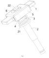
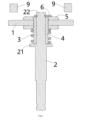
図1~図3は、本発明の第1の実施形態によるコンタクタ可動コンタクトアセンブリを示す。その中でも、図1は、本発明の第1の実施形態によるコンタクタ可動コンタクトアセンブリの例示的な斜視図を示す。図2は、可動コンタクト1が、静止コンタクト9から電気的に分離される開位置にある、本発明の第1の実施形態によるコンタクタ可動コンタクトアセンブリの軸方向断面図を示す。図3は、可動コンタクト1が、静止コンタクト9と電気的に接触する閉位置にある、本発明の第1の実施形態によるコンタクタ可動コンタクトアセンブリの軸方向断面図を示す。
1 to 3 show a contactor movable contact assembly according to a first embodiment of the present invention. Among them, Fig. 1 shows an exemplary perspective view of the contactor movable contact assembly according to the first embodiment of the present invention. Fig. 2 shows an axial cross-sectional view of the contactor movable contact assembly according to the first embodiment of the present invention, in which the
図1~図3に示すように、本発明の例示的な実施形態では、コンタクタ可動コンタクトアセンブリが開示される。コンタクタ可動コンタクトアセンブリは、可動コンタクト1、駆動シャフト2、ばね部品3、およびインシュレータ4を備える。駆動シャフト2には、肩部21が形成されている。可動コンタクト1は、駆動シャフト2に軸方向に移動可能に設置され、肩部21よりも上方に位置している。ばね部品3は、可動コンタクト1の肩部21と駆動シャフト2との間で軸方向に圧縮される。インシュレータ4は、駆動シャフト2を可動コンタクト1から電気的に絶縁するために駆動シャフト2に固定されている。駆動シャフト2は、上述の可動コンタクト1を、静止コンタクト9から電気的に分離される開位置から静止コンタクト9と電気的に接触する閉位置まで駆動するために使用される。
可動コンタクト1が、閉位置に移動すると、ばね部品3は、可動コンタクト1に所定の接触圧を加えて、可動コンタクト1と静止コンタクト9との間の確実な電気接触を確保する。駆動シャフト2と可動コンタクト1との間の沿面距離を長くするために、駆動シャフト2の肩部21と上端22との間の部分が、インシュレータ4に十分に(完全に)覆われている。
As shown in Figures 1 to 3, in an exemplary embodiment of the present invention, a contactor movable contact assembly is disclosed. The contactor movable contact assembly includes a
When the
図1~図3に示すように、図示の実施形態では、コンタクタ可動コンタクトアセンブリは、絶縁フレーム5をさらに備える。絶縁フレーム5は、補助コンタクト(図示せず)を駆動し、ばね部品3を可動コンタクト1から電気的に絶縁するために可動コンタクト1に固定されている。絶縁フレーム5および可動コンタクト1には、インシュレータ4が通過できるように貫通孔が形成されている。
As shown in Figures 1 to 3, in the illustrated embodiment, the contactor movable contact assembly further includes an insulating
図1~図3に示すように、図示の実施形態では、インシュレータ4は、円筒状であり、駆動シャフト2の肩部21の上面から駆動シャフト2の上端22の近傍まで連続的に延びる。ばね部品3は、インシュレータ4に設置され、その上端および下端が、それぞれ、絶縁フレーム5の底面および駆動シャフト2の肩部21の上面に対して押圧される。
As shown in Figures 1 to 3, in the illustrated embodiment, the
図1~図3に示すように、図示の実施形態では、駆動シャフト2の上端22は、インシュレータ4から露出し、駆動シャフト2の上端22には、制限リング6が設置される。図2に示すように、可動コンタクト1が開位置にあるとき、制限リング6は、絶縁フレーム5の上面に対して押圧されて、可動コンタクト1を駆動シャフト2に対して所定の位置に制限する。図3に示すように、可動コンタクト1が閉位置にあるとき、可動コンタクト1は、制限リング6に対して所定の距離だけ軸方向に移動し、これにより、制限リング6は、所定の距離だけ絶縁フレーム5から分離される。
As shown in Figures 1 to 3, in the illustrated embodiment, the
図1~図3に示すように、図示の実施形態では、インシュレータ4は、埋め込み射出成形プロセスを通して駆動シャフト2に形成されており、これにより、インシュレータ4と駆動シャフト4とが、一体部品として形成されている。
As shown in Figures 1-3, in the illustrated embodiment, the
図示していないが、本発明の別の例示的な実施形態では、コンタクタも開示される。コンタクタは、ハウジング、静止コンタクト、コイル、および上述のコンタクタ可動コンタクトアセンブリを備える。静止コンタクトは、ハウジングに固定される。コイルは、ハウジングに設置される。コンタクタ可動コンタクトアセンブリは、ハウジングに移動可能に配置される。コイルが通電されると、駆動シャフト2は、コイルによって発生した電磁力により、可動コンタクト1を開位置から閉位置まで駆動する。
Although not shown, in another exemplary embodiment of the present invention, a contactor is also disclosed. The contactor includes a housing, a stationary contact, a coil, and the contactor movable contact assembly described above. The stationary contact is fixed to the housing. The coil is mounted on the housing. The contactor movable contact assembly is movably disposed on the housing. When the coil is energized, the
図示していないが、本発明の別の例示的な実施形態では、補助コンタクトなしのコンタクタも開示される。コンタクタは、ハウジングと、ハウジングに設けられた座部と、ハウジングに設置された磁気回路アセンブリと、磁気回路アセンブリに設置されたコイルアセンブリと、座部に固定された静止コンタクトと、ハウジングに移動可能に配置された、上記コンタクタ可動コンタクトアセンブリとを備える。コイルアセンブリが通電されると、駆動シャフト2は、コイルアセンブリおよび磁気回路アセンブリによって発生した電磁力により可動コンタクト1を開位置から閉位置まで駆動する。
Although not shown, in another exemplary embodiment of the present invention, a contactor without an auxiliary contact is also disclosed. The contactor includes a housing, a seat provided in the housing, a magnetic circuit assembly installed in the housing, a coil assembly installed in the magnetic circuit assembly, a stationary contact fixed to the seat, and the contactor movable contact assembly movably arranged in the housing. When the coil assembly is energized, the
図示していないが、本発明の別の例示的な実施形態では、補助コンタクトありのコンタクタも開示される。コンタクタは、ハウジングと、ハウジングに設けられた座部と、ハウジングに設置された磁気回路アセンブリと、磁気回路アセンブリに設置されたコイルアセンブリと、座部に固定された静止コンタクトと、基部に固定された補助コンタクトと、ハウジングに移動可能に配置された、上記コンタクタ可動コンタクトアセンブリとを備える。コイルアセンブリが通電されると、駆動シャフト2は、コイルアセンブリおよび磁気回路アセンブリによって発生した電磁力により可動コンタクト1を開位置から閉位置まで駆動するとともに、補助コンタクトを駆動してその接触状態を変更する。例えば、補助コンタクトを開状態から閉状態、または閉状態から開状態に変更する。
Although not shown, in another exemplary embodiment of the present invention, a contactor with an auxiliary contact is also disclosed. The contactor includes a housing, a seat provided in the housing, a magnetic circuit assembly installed in the housing, a coil assembly installed in the magnetic circuit assembly, a stationary contact fixed to the seat, an auxiliary contact fixed to a base, and the contactor movable contact assembly movably arranged in the housing. When the coil assembly is energized, the
第2の実施形態
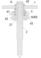
図4および図5は、本発明の第2の実施形態によるコンタクタ可動コンタクトアセンブリを示す。その中でも、図4は、可動コンタクト1が、静止コンタクト9から電気的に分離される開位置にある、本発明の第2の実施形態によるコンタクタ可動コンタクトアセンブリの軸方向断面図を示す。図5は、可動コンタクト1が、静止コンタクト9と電気的に接触する閉位置にある、本発明の第2の実施形態によるコンタクタ可動コンタクトアセンブリの軸方向断面図を示す。
Second embodiment Figures 4 and 5 show a contactor movable contact assembly according to a second embodiment of the present invention. Among them, Figure 4 shows an axial cross-sectional view of the contactor movable contact assembly according to the second embodiment of the present invention, in which the
図4および図5に示すように、本発明の例示的な実施形態では、コンタクタ可動コンタクトアセンブリが開示される。コンタクタ可動コンタクトアセンブリは、可動コンタクト1、駆動シャフト2、ばね部品3、およびインシュレータ4を備える。駆動シャフト2には、肩部21が形成されている。可動コンタクト1は、駆動シャフト2に軸方向に移動可能に設置され、肩部21よりも上方に位置している。ばね部品3は、可動コンタクト1の肩部21と駆動シャフト2との間で軸方向に圧縮される。インシュレータ4は、駆動シャフト2を可動コンタクト1から電気的に絶縁するために駆動シャフト2に固定されている。駆動シャフト2は、上述の可動コンタクト1を、静止コンタクト9から電気的に分離される開位置から静止コンタクト9と電気的に接触する閉位置まで駆動するために使用される。
可動コンタクト1が、閉位置に移動すると、ばね部品3は、可動コンタクト1に所定の接触圧を加えて、可動コンタクト1と静止コンタクト9との間の確実な電気接触を確保する。駆動シャフト2と可動コンタクト1との間の沿面距離を長くするために、駆動シャフト2の肩部21よりも上方の部分が、インシュレータ4に十分に(完全に)覆われている。
As shown in Fig. 4 and Fig. 5, in an exemplary embodiment of the present invention, a contactor movable contact assembly is disclosed. The contactor movable contact assembly includes a
When the
図4および図5に示すように、図示の実施形態では、インシュレータ4の基部40に環状溝41が形成されている。ばね部品3は、インシュレータ4の環状溝41に収容される。ばね部品3の上端および下端は、それぞれ、可動コンタクト1の底面およびインシュレータ4の環状溝41の内側底面に対して押圧される。
As shown in Figures 4 and 5, in the illustrated embodiment, an
図4および図5に示すように、図示の実施形態では、コンタクタ可動コンタクトアセンブリは、絶縁フレーム5をさらに備える。絶縁フレーム5は、補助コンタクト(図示せず)を駆動するために可動コンタクト1に固定される。絶縁フレーム5および可動コンタクト1には、インシュレータ4が通過できるように貫通孔が形成されている。
As shown in Figures 4 and 5, in the illustrated embodiment, the contactor movable contact assembly further includes an insulating
図4および図5に示すように、図示の実施形態では、インシュレータ4の上端に制限リング6が設置される。図4に示すように、可動コンタクト1が開位置にあるとき、制限リング6は、絶縁フレーム5の上面に対して押圧されて、可動コンタクト1を駆動シャフト2に対して所定位置に制限する。図5に示すように、可動コンタクト1が閉位置にあるとき、可動コンタクト1は、制限リング6に対して所定の距離だけ軸方向に移動し、これにより、制限リング6は、絶縁フレーム5から所定の距離だけ分離される。
As shown in Figures 4 and 5, in the illustrated embodiment, a limiting
図4および図5に示すように、図示の実施形態では、可動コンタクト1と駆動シャフト2との間の沿面距離をさらに長くするために、駆動シャフト2の肩部21の上面および外周面が、インシュレータ4の基部40に十分に(完全に)覆われている。
As shown in Figures 4 and 5, in the illustrated embodiment, the upper surface and outer peripheral surface of the
図4および図5に示すように、図示の実施形態では、可動コンタクト1と駆動シャフト2との間の沿面距離をさらに長くするために、インシュレータ4の基部40の外周面に、径方向に突出した環状フランジ43が形成されている。
As shown in Figures 4 and 5, in the illustrated embodiment, a radially protruding
図4および図5に示すように、図示の実施形態では、インシュレータ4の基部40の外周面に複数の環状フランジ43が形成されており、複数の環状フランジ43は、互いに軸方向に離隔されている。
As shown in Figures 4 and 5, in the illustrated embodiment, a plurality of
図4および図5に示すように、図示の実施形態では、インシュレータ4は、埋め込み射出成形プロセスを通して駆動シャフト2上に成形されており、これにより、インシュレータ4と駆動シャフト2とが一体部品として形成されている。
As shown in Figures 4 and 5, in the illustrated embodiment, the
図示していないが、本発明の別の例示的な実施形態では、コンタクタも開示される。コンタクタは、ハウジング、静止コンタクト、コイル、および上述のコンタクタ可動コンタクトアセンブリを備える。静止コンタクトは、ハウジングに固定される。コイルは、ハウジングに設置される。コンタクタ可動コンタクトアセンブリは、ハウジングに移動可能に配置される。コイルが通電されると、駆動シャフト2は、コイルによって発生した電磁力により、可動コンタクト1を開位置から閉位置まで駆動する。
Although not shown, in another exemplary embodiment of the present invention, a contactor is also disclosed. The contactor includes a housing, a stationary contact, a coil, and the contactor movable contact assembly described above. The stationary contact is fixed to the housing. The coil is mounted on the housing. The contactor movable contact assembly is movably disposed on the housing. When the coil is energized, the
図示していないが、本発明の別の例示的な実施形態では、補助コンタクトなしのコンタクタも開示される。コンタクタは、ハウジングと、ハウジングに設けられた座部と、ハウジングに設置された磁気回路アセンブリと、磁気回路アセンブリに設置されたコイルアセンブリと、座部に固定された静止コンタクトと、ハウジングに移動可能に配置された、上記コンタクタ可動コンタクトアセンブリとを備える。コイルアセンブリが通電されると、駆動シャフト2は、コイルアセンブリおよび磁気回路アセンブリによって発生した電磁力により可動コンタクト1を開位置から閉位置まで駆動する。
Although not shown, in another exemplary embodiment of the present invention, a contactor without an auxiliary contact is also disclosed. The contactor includes a housing, a seat provided in the housing, a magnetic circuit assembly installed in the housing, a coil assembly installed in the magnetic circuit assembly, a stationary contact fixed to the seat, and the contactor movable contact assembly movably arranged in the housing. When the coil assembly is energized, the
図示していないが、本発明の別の例示的な実施形態では、補助コンタクトありのコンタクタも開示される。コンタクタは、ハウジングと、ハウジングに設けられた座部と、ハウジングに設置された磁気回路アセンブリと、磁気回路アセンブリに設置されたコイルアセンブリと、座部に固定された静止コンタクトと、基部に固定された補助コンタクトと、ハウジングに移動可能に配置された、上記コンタクタ可動コンタクトアセンブリとを備える。コイルアセンブリが通電されると、駆動シャフト2は、コイルアセンブリおよび磁気回路アセンブリによって発生した電磁力により可動コンタクト1を開位置から閉位置まで駆動するとともに、補助コンタクトを駆動してその接触状態を変更する。例えば、補助コンタクトを開状態から閉状態、または閉状態から開状態に変更する。
Although not shown, in another exemplary embodiment of the present invention, a contactor with an auxiliary contact is also disclosed. The contactor includes a housing, a seat provided in the housing, a magnetic circuit assembly installed in the housing, a coil assembly installed in the magnetic circuit assembly, a stationary contact fixed to the seat, an auxiliary contact fixed to a base, and the contactor movable contact assembly movably arranged in the housing. When the coil assembly is energized, the
第3の実施形態
図6および図7は、本発明の第3の実施形態によるコンタクタ可動コンタクトアセンブリを示す。その中でも、図6は、可動コンタクト1が、静止コンタクト9から電気的に分離される開位置にある、本発明の第3の実施形態によるコンタクタ可動コンタクトアセンブリの軸方向断面図を示す。図7は、可動コンタクト1が、静止コンタクト9と電気的に接触する閉位置にある、本発明の第3の実施形態によるコンタクタ可動コンタクトアセンブリの軸方向断面図を示す。
Third embodiment Figures 6 and 7 show a contactor movable contact assembly according to a third embodiment of the present invention. Among them, Figure 6 shows an axial cross-sectional view of the contactor movable contact assembly according to the third embodiment of the present invention, in which the
図6および図7に示すように、本発明の例示的な実施形態では、コンタクタ可動コンタクトアセンブリが開示される。コンタクタ可動コンタクトアセンブリは、可動コンタクト1、駆動シャフト2、ばね部品3、およびインシュレータ4を備える。駆動シャフト2には、肩部21が形成されている。可動コンタクト1は、駆動シャフト2に軸方向に移動可能に設置され、肩部21よりも上方に位置している。ばね部品3は、可動コンタクト1の肩部21と駆動シャフト2との間で軸方向に圧縮される。インシュレータ4は、駆動シャフト2を可動コンタクト1から電気的に絶縁するために駆動シャフト2に固定されている。駆動シャフト2は、上述の可動コンタクト1を、静止コンタクト9から電気的に分離される開位置から静止コンタクト9と電気的に接触する閉位置まで駆動するために使用される。
可動コンタクト1が、閉位置に移動すると、ばね部品3は、可動コンタクト1に所定の接触圧を加えて、可動コンタクト1と静止コンタクト9との間の確実な電気接触を確保する。駆動シャフト2と可動コンタクト1との間の沿面距離を長くするために、駆動シャフト2の肩部21よりも上方の部分が、インシュレータ4に十分に(完全に)覆われている。
As shown in Fig. 6 and Fig. 7, in an exemplary embodiment of the present invention, a contactor movable contact assembly is disclosed. The contactor movable contact assembly includes a
When the
図6および図7に示すように、図示の実施形態では、インシュレータ4の基部40に環状溝41が形成されている。ばね部品3は、インシュレータ4の環状溝41に収容される。ばね部品3の上端および下端は、それぞれ、可動コンタクト1の底面およびインシュレータ4の環状溝41の内側底面に対して押圧される。
As shown in Figures 6 and 7, in the illustrated embodiment, an
図6および図7に示すように、図示の実施形態では、インシュレータ4の上端に制限リング6が設置される。図6に示すように、可動コンタクト1が開位置にあるとき、制限リング6は、可動コンタクト1の上面に対して押圧されて、それを駆動シャフト2に対して所定の位置に制限する。図7に示すように、可動コンタクト1が閉位置にあるとき、可動コンタクト1は、制限リング6に対して所定の距離だけ軸方向に移動し、これにより、制限リング6は、所定の距離だけ可動コンタクト1から分離される。
As shown in Figures 6 and 7, in the illustrated embodiment, a limiting
図6および図7に示すように、図示の実施形態では、可動コンタクト1と駆動シャフト2との間の沿面距離をさらに長くするために、駆動シャフト2の肩部21の上面および外周面が、インシュレータ4の基部40に十分に(完全に)覆われている。
As shown in Figures 6 and 7, in the illustrated embodiment, the upper surface and outer peripheral surface of the
図6および図7に示すように、図示の実施形態では、可動コンタクト1と駆動シャフト2との間の沿面距離をさらに長くするために、インシュレータ4の基部40の外周面に、径方向に突出した環状フランジ43が形成されている。
As shown in Figures 6 and 7, in the illustrated embodiment, a radially protruding
図6および図7に示すように、図示の実施形態では、インシュレータ4の基部40の外周面に複数の環状フランジ43が形成されており、複数の環状フランジ43は、互いに軸方向に離隔される。
As shown in Figures 6 and 7, in the illustrated embodiment, a plurality of
図6および図7に示すように、図示の実施形態では、インシュレータ4は、埋め込み射出成形プロセスを通して駆動シャフト2上に成形されており、これにより、インシュレータ4と駆動シャフト2とが一体部品として形成されている。
As shown in Figures 6 and 7, in the illustrated embodiment, the
図示していないが、本発明の別の例示的な実施形態では、コンタクタも開示される。コンタクタは、ハウジング、静止コンタクト、コイル、および上述のコンタクタ可動コンタクトアセンブリを備える。静止コンタクトは、ハウジングに固定される。コイルは、ハウジングに設置される。コンタクタ可動コンタクトアセンブリは、ハウジングに移動可能に配置される。コイルが通電されると、駆動シャフト2は、コイルによって発生した電磁力により、可動コンタクト1を開位置から閉位置まで駆動する。
Although not shown, in another exemplary embodiment of the present invention, a contactor is also disclosed. The contactor includes a housing, a stationary contact, a coil, and the contactor movable contact assembly described above. The stationary contact is fixed to the housing. The coil is mounted on the housing. The contactor movable contact assembly is movably disposed on the housing. When the coil is energized, the
図示していないが、本発明の別の例示的な実施形態では、補助コンタクトなしのコンタクタも開示される。コンタクタは、ハウジングと、ハウジングに設けられた座部と、ハウジングに設置された磁気回路アセンブリと、磁気回路アセンブリに設置されたコイルアセンブリと、座部に固定された静止コンタクトと、ハウジングに移動可能に配置された、上記コンタクタ可動コンタクトアセンブリとを備える。コイルアセンブリが通電されると、駆動シャフト2は、コイルアセンブリおよび磁気回路アセンブリによって発生した電磁力により可動コンタクト1を開位置から閉位置まで駆動する。
Although not shown, in another exemplary embodiment of the present invention, a contactor without an auxiliary contact is also disclosed. The contactor includes a housing, a seat provided in the housing, a magnetic circuit assembly installed in the housing, a coil assembly installed in the magnetic circuit assembly, a stationary contact fixed to the seat, and the contactor movable contact assembly movably arranged in the housing. When the coil assembly is energized, the
図示していないが、本発明の別の例示的な実施形態では、補助コンタクトありのコンタクタも開示される。コンタクタは、ハウジングと、ハウジングに設けられた座部と、ハウジングに設置された磁気回路アセンブリと、磁気回路アセンブリに設置されたコイルアセンブリと、座部に固定された静止コンタクトと、基部に固定された補助コンタクトと、ハウジングに移動可能に配置された、上記コンタクタ可動コンタクトアセンブリとを備える。コイルアセンブリが通電されると、駆動シャフト2は、コイルアセンブリおよび磁気回路アセンブリによって発生した電磁力により可動コンタクト1を開位置から閉位置まで駆動するとともに、補助コンタクトを駆動してその接触状態を変更する。例えば、補助コンタクトを開状態から閉状態、または閉状態から開状態に変更する。
Although not shown, in another exemplary embodiment of the present invention, a contactor with an auxiliary contact is also disclosed. The contactor includes a housing, a seat provided in the housing, a magnetic circuit assembly installed in the housing, a coil assembly installed in the magnetic circuit assembly, a stationary contact fixed to the seat, an auxiliary contact fixed to a base, and the contactor movable contact assembly movably arranged in the housing. When the coil assembly is energized, the
第4の実施形態
図8は、可動コンタクト1が、静止コンタクト9から電気的に分離される開位置にある、本発明の第4の実施形態によるコンタクタ可動コンタクトアセンブリの軸方向断面図を示す。
Fourth Embodiment FIG. 8 shows an axial cross-sectional view of a contactor movable contact assembly according to a fourth embodiment of the present invention, in which the
図8に示すように、本発明の例示的な実施形態では、コンタクタ可動コンタクトアセンブリが開示される。コンタクタ可動コンタクトアセンブリは、可動コンタクト1、駆動シャフト2、ばね部品3、およびインシュレータ4を備える。駆動シャフト2には、肩部21が形成されている。可動コンタクト1は、駆動シャフト2に軸方向に移動可能に設置され、肩部21よりも上方に位置している。ばね部品3は、可動コンタクト1の肩部21と駆動シャフト2との間で軸方向に圧縮される。インシュレータ4は、駆動シャフト2を可動コンタクト1から電気的に絶縁するために駆動シャフト2に固定されている。駆動シャフト2は、上述の可動コンタクト1を、静止コンタクト9から電気的に分離される開位置から静止コンタクト9と電気的に接触する閉位置まで駆動するために使用される。
可動コンタクト1が、閉位置に移動すると、ばね部品3は、可動コンタクト1に所定の接触圧を加えて、可動コンタクト1と静止コンタクト9との間の確実な電気接触を確保する。駆動シャフト2と可動コンタクト1との間の沿面距離を長くするために、駆動シャフト2の肩部21よりも上方の部分が、インシュレータ4に十分に(完全に)覆われている。
As shown in FIG. 8, in an exemplary embodiment of the present invention, a contactor movable contact assembly is disclosed. The contactor movable contact assembly includes a
When the
図8に示すように、図示の実施形態では、インシュレータ4の基部40に環状溝41が形成されている。ばね部品3は、インシュレータ4の環状溝41に収容される。ばね部品3の上端および下端は、それぞれ、可動コンタクト1の底面およびインシュレータ4の環状溝41の内側底面に対して押圧される。
As shown in FIG. 8, in the illustrated embodiment, an
図8に示すように、図示の実施形態では、インシュレータ4の上端に制限リング6が設置される。図8に示すように、可動コンタクト1が開位置にあるとき、制限リング6は、可動コンタクト1の上面に対して押圧されて、それを駆動シャフト2に対して所定の位置に制限する。可動コンタクト1が閉位置にあるとき、可動コンタクト1は、制限リング6に対して所定の距離だけ軸方向に移動し、これにより、制限リング6は、所定の距離だけ可動コンタクト1から分離される。
As shown in FIG. 8, in the illustrated embodiment, a limiting
図8に示すように、図示の実施形態では、可動コンタクト1と駆動シャフト2との間の沿面距離をさらに長くするために、駆動シャフト2の肩部21の上面および外周面が、インシュレータ4の基部40に十分に(完全に)覆われている。
As shown in FIG. 8, in the illustrated embodiment, the upper surface and outer peripheral surface of the
図8に示すように、図示の実施形態では、インシュレータ4は、埋め込み射出成形プロセスを通して駆動シャフト2に形成されており、これにより、インシュレータ4と駆動シャフト2とが一体部品となっている。
As shown in FIG. 8, in the illustrated embodiment, the
図示していないが、本発明の別の例示的な実施形態では、コンタクタも開示される。コンタクタは、ハウジング、静止コンタクト、コイル、および上述のコンタクタ可動コンタクトアセンブリを備える。静止コンタクトは、ハウジングに固定される。コイルは、ハウジングに設置される。コンタクタ可動コンタクトアセンブリは、ハウジングに移動可能に配置される。コイルが通電されると、駆動シャフト2は、コイルによって発生した電磁力により、可動コンタクト1を開位置から閉位置まで駆動する。
Although not shown, in another exemplary embodiment of the present invention, a contactor is also disclosed. The contactor includes a housing, a stationary contact, a coil, and the contactor movable contact assembly described above. The stationary contact is fixed to the housing. The coil is mounted on the housing. The contactor movable contact assembly is movably disposed on the housing. When the coil is energized, the
図示していないが、本発明の別の例示的な実施形態では、補助コンタクトなしのコンタクタも開示される。コンタクタは、ハウジングと、ハウジングに設けられた座部と、ハウジングに設置された磁気回路アセンブリと、磁気回路アセンブリに設置されたコイルアセンブリと、座部に固定された静止コンタクトと、ハウジングに移動可能に配置された、上記コンタクタ可動コンタクトアセンブリとを備える。コイルアセンブリが通電されると、駆動シャフト2は、コイルアセンブリおよび磁気回路アセンブリによって発生した電磁力により可動コンタクト1を開位置から閉位置まで駆動する。
Although not shown, in another exemplary embodiment of the present invention, a contactor without an auxiliary contact is also disclosed. The contactor includes a housing, a seat provided in the housing, a magnetic circuit assembly installed in the housing, a coil assembly installed in the magnetic circuit assembly, a stationary contact fixed to the seat, and the contactor movable contact assembly movably arranged in the housing. When the coil assembly is energized, the
図示していないが、本発明の別の例示的な実施形態では、補助コンタクトありのコンタクタも開示される。コンタクタは、ハウジングと、ハウジングに設けられた座部と、ハウジングに設置された磁気回路アセンブリと、磁気回路アセンブリに設置されたコイルアセンブリと、座部に固定された静止コンタクトと、基部に固定された補助コンタクトと、ハウジングに移動可能に配置された、上記コンタクタ可動コンタクトアセンブリとを備える。コイルアセンブリが通電されると、駆動シャフト2は、コイルアセンブリおよび磁気回路アセンブリによって発生した電磁力により可動コンタクト1を開位置から閉位置まで駆動するとともに、補助コンタクトを駆動してその接触状態を変更する。例えば、補助コンタクトを開状態から閉状態、または閉状態から開状態に変更する。
Although not shown, in another exemplary embodiment of the present invention, a contactor with an auxiliary contact is also disclosed. The contactor includes a housing, a seat provided in the housing, a magnetic circuit assembly installed in the housing, a coil assembly installed in the magnetic circuit assembly, a stationary contact fixed to the seat, an auxiliary contact fixed to a base, and the contactor movable contact assembly movably arranged in the housing. When the coil assembly is energized, the
第5の実施形態
図9は、可動コンタクト1が、静止コンタクト9から電気的に分離される開位置にある、本発明の第5の実施形態によるコンタクタ可動コンタクトアセンブリの軸方向断面図を示す。
Fifth Embodiment FIG. 9 shows an axial cross-sectional view of a contactor movable contact assembly according to a fifth embodiment of the present invention, in which the
図9に示すように、本発明の例示的な実施形態では、コンタクタ可動コンタクトアセンブリが開示される。コンタクタ可動コンタクトアセンブリは、可動コンタクト1、駆動シャフト2、ばね部品3、およびインシュレータ4を備える。駆動シャフト2には、肩部21が形成されている。可動コンタクト1は、駆動シャフト2に軸方向に移動可能に設置され、肩部21よりも上方に位置している。ばね部品3は、可動コンタクト1の肩部21と駆動シャフト2との間で軸方向に圧縮される。インシュレータ4は、駆動シャフト2を可動コンタクト1から電気的に絶縁するために駆動シャフト2に固定されている。駆動シャフト2は、上述の可動コンタクト1を、静止コンタクト9から電気的に分離される開位置から静止コンタクト9と電気的に接触する閉位置まで駆動するために使用される。
可動コンタクト1が、閉位置に移動すると、ばね部品3は、可動コンタクト1に所定の接触圧を加えて、可動コンタクト1と静止コンタクト9との間の確実な電気接触を確保する。駆動シャフト2と可動コンタクト1との間の沿面距離を長くするために、駆動シャフト2の肩部21よりも上方の部分が、インシュレータ4に十分に(完全に)覆われている。
As shown in FIG. 9, in an exemplary embodiment of the present invention, a contactor movable contact assembly is disclosed. The contactor movable contact assembly includes a
When the
図9に示すように、図示の実施形態では、インシュレータ4の基部40に支持段部44が形成されている。ばね部品3の上端および下端は、それぞれ、可動コンタクト1の底面およびインシュレータ4の支持段部44に対して押圧される。
As shown in FIG. 9, in the illustrated embodiment, a
図9に示すように、図示の実施形態では、インシュレータ4の上端に制限リング6が設置される。図9に示すように、可動コンタクト1が開位置にあるとき、制限リング6は、可動コンタクト1の上面に対して押圧されて、それを駆動シャフト2に対して所定の位置に制限する。可動コンタクト1が閉位置にあるとき、可動コンタクト1は、制限リング6に対して所定の距離だけ軸方向に移動し、これにより、制限リング6は、所定の距離だけ可動コンタクト1から分離される。
As shown in FIG. 9, in the illustrated embodiment, a limiting
図9に示すように、図示の実施形態では、可動コンタクト1と駆動シャフト2との間の沿面距離をさらに長くするために、駆動シャフト2の肩部21の上面および外周面が、インシュレータ4の基部40に十分に(完全に)覆われている。
As shown in FIG. 9, in the illustrated embodiment, the upper surface and outer peripheral surface of the
図9に示すように、図示の実施形態では、インシュレータ4は、埋め込み射出成形プロセスを通して駆動シャフト2に形成されており、これにより、インシュレータ4と駆動シャフト2とが一体部品となっている。
As shown in FIG. 9, in the illustrated embodiment, the
図示していないが、本発明の別の例示的な実施形態では、コンタクタも開示される。コンタクタは、ハウジング、静止コンタクト、コイル、および上述のコンタクタ可動コンタクトアセンブリを備える。静止コンタクトは、ハウジングに固定される。コイルは、ハウジングに設置される。コンタクタ可動コンタクトアセンブリは、ハウジングに移動可能に配置される。コイルが通電されると、駆動シャフト2は、コイルによって発生した電磁力により、可動コンタクト1を開位置から閉位置まで駆動する。
Although not shown, in another exemplary embodiment of the present invention, a contactor is also disclosed. The contactor includes a housing, a stationary contact, a coil, and the contactor movable contact assembly described above. The stationary contact is fixed to the housing. The coil is mounted on the housing. The contactor movable contact assembly is movably disposed on the housing. When the coil is energized, the
図示していないが、本発明の別の例示的な実施形態では、補助コンタクトなしのコンタクタも開示される。コンタクタは、ハウジングと、ハウジングに設けられた座部と、ハウジングに設置された磁気回路アセンブリと、磁気回路アセンブリに設置されたコイルアセンブリと、座部に固定された静止コンタクトと、ハウジングに移動可能に配置された、上記コンタクタ可動コンタクトアセンブリとを備える。コイルアセンブリが通電されると、駆動シャフト2は、コイルアセンブリおよび磁気回路アセンブリによって発生した電磁力により可動コンタクト1を開位置から閉位置まで駆動する。
Although not shown, in another exemplary embodiment of the present invention, a contactor without an auxiliary contact is also disclosed. The contactor includes a housing, a seat provided in the housing, a magnetic circuit assembly installed in the housing, a coil assembly installed in the magnetic circuit assembly, a stationary contact fixed to the seat, and the contactor movable contact assembly movably arranged in the housing. When the coil assembly is energized, the
図示していないが、本発明の別の例示的な実施形態では、補助コンタクトありのコンタクタも開示される。コンタクタは、ハウジングと、ハウジングに設けられた座部と、ハウジングに設置された磁気回路アセンブリと、磁気回路アセンブリに設置されたコイルアセンブリと、座部に固定された静止コンタクトと、基部に固定された補助コンタクトと、ハウジングに移動可能に配置された、上記コンタクタ可動コンタクトアセンブリとを備える。コイルアセンブリが通電されると、駆動シャフト2は、コイルアセンブリおよび磁気回路アセンブリによって発生した電磁力により可動コンタクト1を開位置から閉位置まで駆動するとともに、補助コンタクトを駆動してその接触状態を変更する。例えば、補助コンタクトを開状態から閉状態、または閉状態から開状態に変更する。
Although not shown, in another exemplary embodiment of the present invention, a contactor with an auxiliary contact is also disclosed. The contactor includes a housing, a seat provided in the housing, a magnetic circuit assembly installed in the housing, a coil assembly installed in the magnetic circuit assembly, a stationary contact fixed to the seat, an auxiliary contact fixed to a base, and the contactor movable contact assembly movably arranged in the housing. When the coil assembly is energized, the
第6の実施形態
図10は、可動コンタクト1が、静止コンタクト9から電気的に分離される開位置にある、本発明の第6の実施形態によるコンタクタ可動コンタクトアセンブリの軸方向断面図を示す。
Sixth Embodiment FIG. 10 shows an axial cross-sectional view of a contactor movable contact assembly according to a sixth embodiment of the present invention, in which the
図10に示すように、本発明の例示的な実施形態では、コンタクタ可動コンタクトアセンブリが開示される。コンタクタ可動コンタクトアセンブリは、可動コンタクト1、駆動シャフト2、ばね部品3、およびインシュレータ4を備える。駆動シャフト2には、肩部21が形成されている。可動コンタクト1は、駆動シャフト2に軸方向に移動可能に設置され、肩部21よりも上方に位置している。ばね部品3は、可動コンタクト1の肩部21と駆動シャフト2との間で軸方向に圧縮される。インシュレータ4は、駆動シャフト2を可動コンタクト1から電気的に絶縁するために駆動シャフト2に固定されている。駆動シャフト2は、上述の可動コンタクト1を、静止コンタクト9から電気的に分離される開位置から静止コンタクト9と電気的に接触する閉位置まで駆動するために使用される。
可動コンタクト1が、閉位置に移動すると、ばね部品3は、可動コンタクト1に所定の接触圧を加えて、可動コンタクト1と静止コンタクト9との間の確実な電気接触を確保する。駆動シャフト2と可動コンタクト1との間の沿面距離を長くするために、駆動シャフト2の肩部21よりも上方の部分が、インシュレータ4に十分に(完全に)覆われている。
As shown in FIG. 10, in an exemplary embodiment of the present invention, a contactor movable contact assembly is disclosed. The contactor movable contact assembly includes a
When the
図10に示すように、図示の実施形態では、インシュレータ4の基部40に支持段部44が形成されている。ばね部品3の上端および下端は、それぞれ、可動コンタクト1の底面およびインシュレータ4の支持段部44に対して押圧される。
As shown in FIG. 10, in the illustrated embodiment, a
図10に示すように、図示の実施形態では、インシュレータ4の上端に制限リング6が設置される。図10に示すように、可動コンタクト1が開位置にあるとき、制限リング6は、可動コンタクト1の上面に対して押圧されて、それを駆動シャフト2に対して所定の位置に制限する。可動コンタクト1が閉位置にあるとき、可動コンタクト1は、制限リング6に対して所定の距離だけ軸方向に移動し、これにより、制限リング6は、所定の距離だけ可動コンタクト1から分離される。
As shown in FIG. 10, in the illustrated embodiment, a limiting
図10に示すように、図示の実施形態では、可動コンタクト1と駆動シャフト2との間の沿面距離をさらに長くするために、駆動シャフト2の肩部21の上面および外周面が、インシュレータ4の基部40に十分に(完全に)覆われている。
As shown in FIG. 10, in the illustrated embodiment, the upper surface and outer peripheral surface of the
図10に示すように、図示の実施形態では、可動コンタクト1と駆動シャフト2との間の沿面距離をさらに長くするために、インシュレータ4の基部40の外周面に、径方向に突出した環状フランジ43が形成されている。
As shown in FIG. 10, in the illustrated embodiment, a radially protruding
図10に示すように、図示の実施形態では、インシュレータ4は、埋め込み射出成形プロセスを通して駆動シャフト2に形成されており、これにより、インシュレータ4と駆動シャフト2とが一体部品となっている。
As shown in FIG. 10, in the illustrated embodiment, the
図示していないが、本発明の別の例示的な実施形態では、コンタクタも開示される。コンタクタは、ハウジング、静止コンタクト、コイル、および上述のコンタクタ可動コンタクトアセンブリを備える。静止コンタクトは、ハウジングに固定される。コイルは、ハウジングに設置される。コンタクタ可動コンタクトアセンブリは、ハウジングに移動可能に配置される。コイルが通電されると、駆動シャフト2は、コイルによって発生した電磁力により、可動コンタクト1を開位置から閉位置まで駆動する。
Although not shown, in another exemplary embodiment of the present invention, a contactor is also disclosed. The contactor includes a housing, a stationary contact, a coil, and the contactor movable contact assembly described above. The stationary contact is fixed to the housing. The coil is mounted on the housing. The contactor movable contact assembly is movably disposed on the housing. When the coil is energized, the
図示していないが、本発明の別の例示的な実施形態では、補助コンタクトなしのコンタクタも開示される。コンタクタは、ハウジングと、ハウジングに設けられた座部と、ハウジングに設置された磁気回路アセンブリと、磁気回路アセンブリに設置されたコイルアセンブリと、座部に固定された静止コンタクトと、ハウジングに移動可能に配置された、上記コンタクタ可動コンタクトアセンブリとを備える。コイルアセンブリが通電されると、駆動シャフト2は、コイルアセンブリおよび磁気回路アセンブリによって発生した電磁力により可動コンタクト1を開位置から閉位置まで駆動する。
Although not shown, in another exemplary embodiment of the present invention, a contactor without an auxiliary contact is also disclosed. The contactor includes a housing, a seat provided in the housing, a magnetic circuit assembly installed in the housing, a coil assembly installed in the magnetic circuit assembly, a stationary contact fixed to the seat, and the contactor movable contact assembly movably arranged in the housing. When the coil assembly is energized, the
図示していないが、本発明の別の例示的な実施形態では、補助コンタクトありのコンタクタも開示される。コンタクタは、ハウジングと、ハウジングに設けられた座部と、ハウジングに設置された磁気回路アセンブリと、磁気回路アセンブリに設置されたコイルアセンブリと、座部に固定された静止コンタクトと、基部に固定された補助コンタクトと、ハウジングに移動可能に配置された、上記コンタクタ可動コンタクトアセンブリとを備える。コイルアセンブリが通電されると、駆動シャフト2は、コイルアセンブリおよび磁気回路アセンブリによって発生した電磁力により可動コンタクト1を開位置から閉位置まで駆動するとともに、補助コンタクトを駆動してその接触状態を変更する。例えば、補助コンタクトを開状態から閉状態、または閉状態から開状態に変更する。
Although not shown, in another exemplary embodiment of the present invention, a contactor with an auxiliary contact is also disclosed. The contactor includes a housing, a seat provided in the housing, a magnetic circuit assembly installed in the housing, a coil assembly installed in the magnetic circuit assembly, a stationary contact fixed to the seat, an auxiliary contact fixed to a base, and the contactor movable contact assembly movably arranged in the housing. When the coil assembly is energized, the
第7の実施形態
図11は、可動コンタクト1が、静止コンタクト9から電気的に分離される開位置にある、本発明の第7の実施形態によるコンタクタ可動コンタクトアセンブリの軸方向断面図を示す。
Seventh Embodiment FIG. 11 shows an axial cross-sectional view of a contactor movable contact assembly according to a seventh embodiment of the present invention, in which the
図11に示すように、本発明の例示的な実施形態では、コンタクタ可動コンタクトアセンブリが開示される。コンタクタ可動コンタクトアセンブリは、可動コンタクト1、駆動シャフト2、ばね部品3、およびインシュレータ4を備える。駆動シャフト2には、肩部21が形成されている。可動コンタクト1は、駆動シャフト2に軸方向に移動可能に設置され、肩部21よりも上方に位置している。ばね部品3は、可動コンタクト1の肩部21と駆動シャフト2との間で軸方向に圧縮される。インシュレータ4は、駆動シャフト2を可動コンタクト1から電気的に絶縁するために駆動シャフト2に固定されている。駆動シャフト2は、上述の可動コンタクト1を、静止コンタクト9から電気的に分離される開位置から静止コンタクト9と電気的に接触する閉位置まで駆動するために使用される。
可動コンタクト1が、閉位置に移動すると、ばね部品3は、可動コンタクト1に所定の接触圧を加えて、可動コンタクト1と静止コンタクト9との間の確実な電気接触を確保する。駆動シャフト2と可動コンタクト1との間の沿面距離を長くするために、駆動シャフト2の肩部21よりも上方の部分が、インシュレータ4に十分に(完全に)覆われている。
As shown in FIG. 11 , in an exemplary embodiment of the present invention, a contactor movable contact assembly is disclosed. The contactor movable contact assembly includes a
When the
図11に示すように、図示の実施形態では、インシュレータ4の基部40に環状溝41が形成されている。ばね部品3は、インシュレータ4の環状溝41に収容される。ばね部品3の上端および下端は、それぞれ、可動コンタクト1の底面およびインシュレータ4の環状溝41の内側底面に対して押圧される。
As shown in FIG. 11, in the illustrated embodiment, an
図11に示すように、図示の実施形態では、インシュレータ4の上端に制限リング6が設置される。図11に示すように、可動コンタクト1が開位置にあるとき、制限リング6は、可動コンタクト1の上面に対して押圧されて、それを駆動シャフト2に対して所定の位置に制限する。可動コンタクト1が閉位置にあるとき、可動コンタクト1は、制限リング6に対して所定の距離だけ軸方向に移動し、これにより、制限リング6は、所定の距離だけ可動コンタクト1から分離される。
As shown in FIG. 11, in the illustrated embodiment, a limiting
図11に示すように、図示の実施形態では、可動コンタクト1と駆動シャフト2との間の沿面距離をさらに長くするために、駆動シャフト2の肩部21の上面および外周面が、インシュレータ4の基部40に十分に(完全に)覆われている。
As shown in FIG. 11, in the illustrated embodiment, the upper surface and outer peripheral surface of the
図11に示すように、図示の実施形態では、可動コンタクト1と駆動シャフト2との間の沿面距離をさらに長くするために、インシュレータ4の基部40の外周面に、径方向に突出した環状フランジ43が形成されている。
As shown in FIG. 11, in the illustrated embodiment, a radially protruding
図11に示すように、図示の実施形態では、インシュレータ4は、埋め込み射出成形プロセスを通して駆動シャフト2上に成形されており、これにより、インシュレータ4と駆動シャフト2とが一体部品として形成されている。
As shown in FIG. 11, in the illustrated embodiment, the
図示していないが、本発明の別の例示的な実施形態では、コンタクタも開示される。コンタクタは、ハウジング、静止コンタクト、コイル、および上述のコンタクタ可動コンタクトアセンブリを備える。静止コンタクトは、ハウジングに固定される。コイルは、ハウジングに設置される。コンタクタ可動コンタクトアセンブリは、ハウジングに移動可能に配置される。コイルが通電されると、駆動シャフト2は、コイルによって発生した電磁力により、可動コンタクト1を開位置から閉位置まで駆動する。
Although not shown, in another exemplary embodiment of the present invention, a contactor is also disclosed. The contactor includes a housing, a stationary contact, a coil, and the contactor movable contact assembly described above. The stationary contact is fixed to the housing. The coil is mounted on the housing. The contactor movable contact assembly is movably disposed on the housing. When the coil is energized, the
図示していないが、本発明の別の例示的な実施形態では、補助コンタクトなしのコンタクタも開示される。コンタクタは、ハウジングと、ハウジングに設けられた座部と、ハウジングに設置された磁気回路アセンブリと、磁気回路アセンブリに設置されたコイルアセンブリと、座部に固定された静止コンタクトと、ハウジングに移動可能に配置された、上記コンタクタ可動コンタクトアセンブリとを備える。コイルアセンブリが通電されると、駆動シャフト2は、コイルアセンブリおよび磁気回路アセンブリによって発生した電磁力により可動コンタクト1を開位置から閉位置まで駆動する。
Although not shown, in another exemplary embodiment of the present invention, a contactor without an auxiliary contact is also disclosed. The contactor includes a housing, a seat provided in the housing, a magnetic circuit assembly installed in the housing, a coil assembly installed in the magnetic circuit assembly, a stationary contact fixed to the seat, and the contactor movable contact assembly movably arranged in the housing. When the coil assembly is energized, the
図示していないが、本発明の別の例示的な実施形態では、補助コンタクトありのコンタクタも開示される。コンタクタは、ハウジングと、ハウジングに設けられた座部と、ハウジングに設置された磁気回路アセンブリと、磁気回路アセンブリに設置されたコイルアセンブリと、座部に固定された静止コンタクトと、基部に固定された補助コンタクトと、ハウジングに移動可能に配置された、上記コンタクタ可動コンタクトアセンブリとを備える。コイルアセンブリが通電されると、駆動シャフト2は、コイルアセンブリおよび磁気回路アセンブリによって発生した電磁力により可動コンタクト1を開位置から閉位置まで駆動するとともに、補助コンタクトを駆動してその接触状態を変更する。例えば、補助コンタクトを開状態から閉状態、または閉状態から開状態に変更する。
Although not shown, in another exemplary embodiment of the present invention, a contactor with an auxiliary contact is also disclosed. The contactor includes a housing, a seat provided in the housing, a magnetic circuit assembly installed in the housing, a coil assembly installed in the magnetic circuit assembly, a stationary contact fixed to the seat, an auxiliary contact fixed to a base, and the contactor movable contact assembly movably arranged in the housing. When the coil assembly is energized, the
上記の実施形態は例示的なものであり、限定的なものではないことを、当業者には理解されたい。例えば、当業者であれば、構成上または原理上矛盾することなく、上記の実施形態に多くの修正を加えることができ、異なる実施形態に記載する様々な特徴を互いに自由に組み合わせることができる。 Those skilled in the art should understand that the above-described embodiments are illustrative and not limiting. For example, those skilled in the art can make many modifications to the above-described embodiments without any contradiction in structure or principle, and can freely combine various features described in different embodiments with each other.
いくつかの例示的な実施形態について図示し説明したが、本開示の原理および趣旨から逸脱することなく、これらの実施形態に様々な変更または修正を加えることができることが、当業者には理解されよう。本開示の範囲は、特許請求の範囲およびその均等物により定義される。 Although several exemplary embodiments have been shown and described, it will be understood by those skilled in the art that various changes or modifications can be made to these embodiments without departing from the principles and spirit of the present disclosure. The scope of the present disclosure is defined by the claims and their equivalents.
本明細書で使用されるとき、単数形で記載され「a」または「an」という単語が前に付く要素は、前記要素またはステップの複数形を除外することが明示的に述べられていない限り、これらを除外しないものとして理解すべきである。さらに、本発明の「一実施形態」への言及は、記載された特徴を同じく組み込む追加の実施形態の存在を除外するものとして解釈されることを意図していない。さらに、そうではないと明示的に述べられていない限り、特定の特性を有する1つの要素もしくは複数の要素を「備える」または「有する」実施形態は、その特性を有していない追加のそのような要素を含んでよい。 As used herein, elements described in the singular and preceded by the word "a" or "an" should be understood as not excluding a plurality of said elements or steps, unless expressly stated to the contrary. Furthermore, references to "one embodiment" of the invention are not intended to be interpreted as excluding the existence of additional embodiments that also incorporate the recited features. Furthermore, unless expressly stated to the contrary, embodiments "comprising" or "having" an element or elements having a particular characteristic may include additional such elements that do not have that characteristic.
Claims (18)
前記コンタクタ可動コンタクトアセンブリは。
- 肩部(21)が形成された駆動シャフト(2)と、
- 前記駆動シャフト(2)に軸方向に移動可能に設置され、前記肩部(21)よりも上方に位置する可動コンタクト(1)と、
- 前記可動コンタクト(1)の前記肩部(21)と前記駆動シャフト(2)との間で軸方向に圧縮されるばね部品(3)と、
- 前記駆動シャフト(2)を前記可動コンタクト(1)から電気的に絶縁するために前記駆動シャフト(2)に固定されたインシュレータ(4)と
を備え、
前記駆動シャフト(2)は、前記可動コンタクト(1)を、静止コンタクト(9)から電気的に分離される開位置から前記静止コンタクト(9)と電気的に接触する閉位置まで駆動するために使用され、
前記ばね部品(3)は、前記可動コンタクト(1)に所定の接触圧を加えて、前記可動コンタクト(1)と前記静止コンタクト(9)との間に確実な電気接触を確保するために使用され、
前記駆動シャフト(2)と前記可動コンタクト(1)との間の沿面距離を長くするために、前記駆動シャフト(2)の前記肩部(21)と前記駆動シャフト(2)の上端(22)との間の部分が、前記インシュレータ(4)に十分に覆われている、
コンタクタ可動コンタクトアセンブリ。
A contactor movable contact assembly comprising:
The contactor movable contact assembly.
- a drive shaft (2) formed with a shoulder (21);
- a movable contact (1) axially movably mounted on said drive shaft (2) and positioned above said shoulder (21);
- a spring element (3) which is axially compressed between the shoulder (21) of the movable contact (1) and the drive shaft (2);
- an insulator (4) fixed to the drive shaft (2) for electrically insulating the drive shaft (2) from the movable contact (1);
The drive shaft (2) is used to drive the movable contact (1) from an open position in which it is electrically isolated from the stationary contact (9) to a closed position in which it is in electrical contact with the stationary contact (9);
The spring element (3) is used to apply a predetermined contact pressure to the movable contact (1) to ensure reliable electrical contact between the movable contact (1) and the stationary contact (9);
In order to increase the creepage distance between the drive shaft (2) and the movable contact (1), a portion between the shoulder portion (21) of the drive shaft (2) and an upper end (22) of the drive shaft (2) is sufficiently covered by the insulator (4).
Contactor movable contact assembly.
請求項1に記載のコンタクタ可動コンタクトアセンブリ。
The upper end (22) of the drive shaft (2) is also sufficiently covered by the insulator (4), so that a portion of the drive shaft (2) above the shoulder portion (21) is sufficiently covered by the insulator (4).
2. The contactor movable contact assembly of claim 1.
前記絶縁フレーム(5)および前記可動コンタクト(1)には、前記インシュレータ(4)が通過できるように貫通孔が形成されている、
請求項1に記載のコンタクタ可動コンタクトアセンブリ。
and an insulating frame (5) fixed to the movable contact (1) for driving an auxiliary contact and electrically insulating the spring part (3) from the movable contact (1).
The insulating frame (5) and the movable contact (1) are formed with a through hole through which the insulator (4) can pass.
2. The contactor movable contact assembly of claim 1.
前記ばね部品(3)は、前記インシュレータ(4)に取り付けられ、前記ばね部品(3)の上端および下端が、それぞれ、前記絶縁フレーム(5)の底面および前記駆動シャフト(2)の前記肩部(21)の前記上面に対して押圧される、
請求項3に記載のコンタクタ可動コンタクトアセンブリ。
The insulator (4) is cylindrical and extends continuously from an upper surface of the shoulder portion (21) of the drive shaft (2) to near the upper end (22) of the drive shaft (2);
The spring part (3) is attached to the insulator (4), and the upper and lower ends of the spring part (3) are pressed against the bottom surface of the insulating frame (5) and the upper surface of the shoulder portion (21) of the drive shaft (2), respectively.
4. The contactor movable contact assembly of claim 3.
前記可動コンタクト(1)が前記開位置にあるとき、前記制限リング(6)は、前記絶縁フレーム(5)の上面に対して押圧されて、前記可動コンタクト(1)を前記駆動シャフト(2)に対して所定の位置に制限し、
前記可動コンタクト(1)が前記閉位置にあるとき、前記可動コンタクト(1)は、前記制限リング(6)に対して所定の距離だけ軸方向に移動し、これにより、前記制限リング(6)は、前記所定の距離だけ前記絶縁フレーム(5)から分離される、
請求項4に記載のコンタクタ可動コンタクトアセンブリ。
The upper end (22) of the drive shaft (2) is exposed from the insulator (4), and a limiting ring (6) is installed on the upper end (22) of the drive shaft (2);
When the movable contact (1) is in the open position, the limiting ring (6) is pressed against the upper surface of the insulating frame (5) to limit the movable contact (1) to a predetermined position relative to the drive shaft (2);
When the movable contact (1) is in the closed position, the movable contact (1) moves axially a predetermined distance relative to the limiting ring (6), whereby the limiting ring (6) is separated from the insulating frame (5) by the predetermined distance.
5. The contactor movable contact assembly of claim 4.
前記ばね部品(3)の上端および下端は、それぞれ、前記可動コンタクト(1)の底面および前記インシュレータ(4)の前記環状溝(41)の内側底面に対して押圧される、
請求項2に記載のコンタクタ可動コンタクトアセンブリ。
An annular groove (41) is formed in a base portion (40) of the insulator (4), and the spring part (3) is accommodated in the annular groove (41) of the insulator (4);
The upper and lower ends of the spring part (3) are pressed against the bottom surface of the movable contact (1) and the inner bottom surface of the annular groove (41) of the insulator (4), respectively.
3. The contactor movable contact assembly of claim 2.
前記絶縁フレーム(5)および前記可動コンタクト(1)には、前記インシュレータ(4)が通過できるように貫通孔が形成されている、
請求項6に記載のコンタクタ可動コンタクトアセンブリ。
Further comprising an insulating frame (5) fixed to the movable contact (1) for driving an auxiliary contact;
The insulating frame (5) and the movable contact (1) are formed with a through hole through which the insulator (4) can pass.
7. The contactor movable contact assembly of claim 6.
前記可動コンタクト(1)が前記開位置にあるとき、前記制限リング(6)は、前記絶縁フレーム(5)の上面に対して押圧されて、前記可動コンタクト(1)を前記駆動シャフト(2)に対して所定の位置に制限し、
前記可動コンタクト(1)が前記閉位置にあるとき、前記可動コンタクト(1)は、前記制限リング(6)に対して所定の距離だけ軸方向に移動し、これにより、前記制限リング(6)は、前記所定の距離だけ前記絶縁フレーム(5)から分離される、
請求項7に記載のコンタクタ可動コンタクトアセンブリ。
A limiting ring (6) is installed at the upper end of the insulator (4),
When the movable contact (1) is in the open position, the limiting ring (6) is pressed against the upper surface of the insulating frame (5) to limit the movable contact (1) in a predetermined position relative to the drive shaft (2);
When the movable contact (1) is in the closed position, the movable contact (1) moves axially a predetermined distance relative to the limiting ring (6), whereby the limiting ring (6) is separated from the insulating frame (5) by the predetermined distance.
8. The contactor movable contact assembly of claim 7.
前記可動コンタクト(1)が前記開位置にあるとき、前記制限リング(6)は、前記可動コンタクト(1)の上面に対して押圧されて、前記可動コンタクト(1)を前記駆動シャフト(2)に対して所定の位置に制限し、
前記可動コンタクト(1)が前記閉位置にあるとき、前記可動コンタクト(1)は、前記制限リング(6)に対して所定の距離だけ軸方向に移動し、これにより、前記制限リング(6)は、前記所定の距離だけ前記可動コンタクト(1)から分離される、
請求項6に記載のコンタクタ可動コンタクトアセンブリ。
A limiting ring (6) is installed at the upper end of the insulator (4),
When the movable contact (1) is in the open position, the limiting ring (6) is pressed against an upper surface of the movable contact (1) to limit the movable contact (1) to a predetermined position relative to the drive shaft (2);
When the movable contact (1) is in the closed position, the movable contact (1) moves axially a predetermined distance relative to the limiting ring (6), whereby the limiting ring (6) is separated from the movable contact (1) by the predetermined distance.
7. The contactor movable contact assembly of claim 6.
前記ばね部品(3)の上端および下端は、それぞれ、前記可動コンタクト(1)の底面および前記インシュレータ(4)の前記支持段部(44)に当接して支持されている、
請求項2に記載のコンタクタ可動コンタクトアセンブリ。
A support step portion (44) is formed on the base portion (40) of the insulator (4),
The upper and lower ends of the spring part (3) are supported by abutting against the bottom surface of the movable contact (1) and the supporting step portion (44) of the insulator (4), respectively.
3. The contactor movable contact assembly of claim 2.
前記可動コンタクト(1)が前記開位置にあるとき、前記制限リング(6)は、前記可動コンタクト(1)の上面に対して押圧されて、前記可動コンタクト(1)を前記駆動シャフト(2)に対して所定の位置に制限し、
前記可動コンタクト(1)が前記閉位置にあるとき、前記可動コンタクト(1)は、前記制限リング(6)に対して所定の距離だけ軸方向に移動し、これにより、前記制限リング(6)は、前記所定の距離だけ前記可動コンタクト(1)から分離される、
請求項10に記載のコンタクタ可動コンタクトアセンブリ。
A limiting ring (6) is installed at the upper end of the insulator (4),
When the movable contact (1) is in the open position, the limiting ring (6) is pressed against an upper surface of the movable contact (1) to limit the movable contact (1) to a predetermined position relative to the drive shaft (2);
When the movable contact (1) is in the closed position, the movable contact (1) moves axially a predetermined distance relative to the limiting ring (6), whereby the limiting ring (6) is separated from the movable contact (1) by the predetermined distance.
The contactor movable contact assembly of claim 10.
請求項2から11のいずれか一項に記載のコンタクタ可動コンタクトアセンブリ。
In order to further increase the creepage distance between the movable contact (1) and the drive shaft (2), an upper surface and an outer circumferential surface of the shoulder portion (21) of the drive shaft (2) are sufficiently covered by a base portion (40) of the insulator (4).
A contactor movable contact assembly according to any one of claims 2 to 11.
請求項2から11のいずれか一項に記載のコンタクタ可動コンタクトアセンブリ。
In order to further increase the creepage distance between the movable contact (1) and the drive shaft (2), an annular flange (43) is formed on the outer circumferential surface of the base (40) of the insulator (4).
A contactor movable contact assembly according to any one of claims 2 to 11.
請求項2から11のいずれか一項に記載のコンタクタ可動コンタクトアセンブリ。
In order to further increase the creepage distance between the movable contact (1) and the drive shaft (2), an upper surface and an outer circumferential surface of the shoulder portion (21) of the drive shaft (2) are sufficiently covered by a base portion (40) of the insulator (4), and an annular flange (43) is formed on the outer circumferential surface of the base portion (40) of the insulator (4).
A contactor movable contact assembly according to any one of claims 2 to 11.
請求項13に記載のコンタクタ可動コンタクトアセンブリ。
A plurality of annular flanges (43) are formed on the outer circumferential surface of the base portion (40) of the insulator (4), and the plurality of annular flanges (43) are spaced apart from one another in the axial direction.
The contactor movable contact assembly of claim 13.
請求項1から11のいずれか一項に記載のコンタクタ可動コンタクトアセンブリ。
The insulator (4) is formed on the drive shaft (2) through an embedded injection molding process, whereby the insulator (4) and the drive shaft (2) are formed as an integral part.
A contactor movable contact assembly according to any one of claims 1 to 11.
前記コンタクタは、
- ハウジングと、
- 前記ハウジングに設けられた座部と、
- 前記ハウジングに設置された磁気回路アセンブリと、
- 前記磁気回路アセンブリに設置されたコイルアセンブリと、
- 前記座部に固定された静止コンタクトと、
- 前記ハウジングに移動可能に配置された、請求項1から16のいずれか一項に記載のコンタクタ可動コンタクトアセンブリと
を備え、
前記コイルアセンブリが通電されると、前記駆動シャフト(2)は、前記コイルアセンブリおよび前記磁気回路アセンブリによって発生した電磁力により前記可動コンタクト(1)を前記開位置から前記閉位置まで駆動する、
補助コンタクトなしのコンタクタ。
A contactor without an auxiliary contact,
The contactor includes:
- Housing;
a seat provided on the housing;
a magnetic circuit assembly mounted in the housing;
a coil assembly disposed on the magnetic circuit assembly;
- a stationary contact fixed to said seat;
- a contactor movable contact assembly according to any one of claims 1 to 16, movably arranged in the housing,
When the coil assembly is energized, the drive shaft (2) drives the movable contact (1) from the open position to the closed position by electromagnetic force generated by the coil assembly and the magnetic circuit assembly.
Contactor without auxiliary contacts.
前記コンタクタは、
- ハウジングと、
- 前記ハウジングに設けられた座部と、
- 前記ハウジングに設置された磁気回路アセンブリと、
- 前記磁気回路アセンブリに設置されたコイルアセンブリと、
- 前記座部に固定された静止コンタクトと、
- 前記座部に固定された補助コンタクトと、
- 前記ハウジングに移動可能に配置された、請求項1から16のいずれか一項に記載のコンタクタ可動コンタクトアセンブリと
を備え、
前記コイルアセンブリが通電されると、前記駆動シャフト(2)は、前記コイルアセンブリおよび前記磁気回路アセンブリによって発生した電磁力により前記可動コンタクト(1)を前記開位置から前記閉位置まで駆動するとともに、前記補助コンタクトを駆動してその接触状態を変更する、
補助コンタクトありのコンタクタ。 A contactor with an auxiliary contact,
The contactor includes:
- Housing;
a seat provided on the housing;
a magnetic circuit assembly mounted in the housing;
a coil assembly disposed on the magnetic circuit assembly;
- a stationary contact fixed to said seat;
- an auxiliary contact fixed to said seat;
- a contactor movable contact assembly according to any one of claims 1 to 16, movably arranged in the housing,
When the coil assembly is energized, the drive shaft (2) drives the movable contact (1) from the open position to the closed position by an electromagnetic force generated by the coil assembly and the magnetic circuit assembly, and drives the auxiliary contact to change its contact state.
Contactor with auxiliary contact.
Applications Claiming Priority (2)
| Application Number | Priority Date | Filing Date | Title |
|---|---|---|---|
| CN202322367305.3U CN220233042U (en) | 2023-08-31 | 2023-08-31 | Contactor moving contact assembly and contactor |
| CN202322367305.3 | 2023-08-31 |
Publications (1)
| Publication Number | Publication Date |
|---|---|
| JP2025036282A true JP2025036282A (en) | 2025-03-14 |
Family
ID=89181509
Family Applications (1)
| Application Number | Title | Priority Date | Filing Date |
|---|---|---|---|
| JP2024146178A Pending JP2025036282A (en) | 2023-08-31 | 2024-08-28 | Contactor movable contact assembly and contactor |
Country Status (4)
| Country | Link |
|---|---|
| US (1) | US20250079100A1 (en) |
| JP (1) | JP2025036282A (en) |
| KR (1) | KR20250033064A (en) |
| CN (1) | CN220233042U (en) |
-
2023
- 2023-08-31 CN CN202322367305.3U patent/CN220233042U/en active Active
-
2024
- 2024-08-27 US US18/815,957 patent/US20250079100A1/en active Pending
- 2024-08-28 JP JP2024146178A patent/JP2025036282A/en active Pending
- 2024-08-29 KR KR1020240116314A patent/KR20250033064A/en active Pending
Also Published As
| Publication number | Publication date |
|---|---|
| CN220233042U (en) | 2023-12-22 |
| KR20250033064A (en) | 2025-03-07 |
| US20250079100A1 (en) | 2025-03-06 |
Similar Documents
| Publication | Publication Date | Title |
|---|---|---|
| JP7069343B2 (en) | relay | |
| US8339222B2 (en) | Electromagnetic relay | |
| JP7722798B2 (en) | Movable contact module, movable contact assembly, movable contact device and contactor | |
| CN112086320A (en) | A high voltage DC relay | |
| US11594386B2 (en) | Medium voltage switching pole | |
| CN102280987B (en) | Bistable permanent magnetic actuator | |
| JP2025036282A (en) | Contactor movable contact assembly and contactor | |
| KR101300264B1 (en) | Switchgear | |
| JP7278230B2 (en) | Switches and winding switching devices | |
| CN220731403U (en) | Novel vacuum circuit breaker | |
| TW202119447A (en) | Circuit breaker | |
| JP2025031619A (en) | Contactor Movable Terminal Assembly and Contactor | |
| US3376528A (en) | Electromagnetic actuating device | |
| US20250246385A1 (en) | Contactor Movable Contact Assembly and Contactor | |
| US20250246386A1 (en) | Contactor Movable Contact Assembly and Contactor | |
| CN217009071U (en) | Contactor coil assembly and contactor | |
| CN223347703U (en) | Relay coil assembly and relay | |
| JP4829097B2 (en) | Electromagnetic actuator | |
| CN219017539U (en) | Contactor moving terminal assembly and contactor | |
| JP6351369B2 (en) | Switchgear | |
| CN220553393U (en) | Contactor moving terminal assembly and contactor | |
| CN221651414U (en) | Contactor moving contact assembly and contactor | |
| KR20160003787U (en) | Relay Actuator | |
| JP2019110009A (en) | Switch | |
| CN115428109B (en) | Arc restraint mechanism |