JP2025011663A - Information processing device - Google Patents
Information processing device Download PDFInfo
- Publication number
- JP2025011663A JP2025011663A JP2023113898A JP2023113898A JP2025011663A JP 2025011663 A JP2025011663 A JP 2025011663A JP 2023113898 A JP2023113898 A JP 2023113898A JP 2023113898 A JP2023113898 A JP 2023113898A JP 2025011663 A JP2025011663 A JP 2025011663A
- Authority
- JP
- Japan
- Prior art keywords
- information
- axis
- drive waveform
- display
- candidates
- Prior art date
- Legal status (The legal status is an assumption and is not a legal conclusion. Google has not performed a legal analysis and makes no representation as to the accuracy of the status listed.)
- Pending
Links
- 230000010365 information processing Effects 0.000 title claims description 53
- 238000011156 evaluation Methods 0.000 claims abstract description 157
- 239000007788 liquid Substances 0.000 claims abstract description 67
- 230000004044 response Effects 0.000 claims description 12
- 238000010586 diagram Methods 0.000 description 41
- 238000012545 processing Methods 0.000 description 33
- 230000008602 contraction Effects 0.000 description 28
- 230000006870 function Effects 0.000 description 21
- 230000015654 memory Effects 0.000 description 21
- 238000005259 measurement Methods 0.000 description 14
- 238000000034 method Methods 0.000 description 8
- 230000008859 change Effects 0.000 description 7
- 238000003384 imaging method Methods 0.000 description 7
- 230000007246 mechanism Effects 0.000 description 7
- 230000007274 generation of a signal involved in cell-cell signaling Effects 0.000 description 5
- 230000008569 process Effects 0.000 description 5
- 230000003287 optical effect Effects 0.000 description 4
- 238000005457 optimization Methods 0.000 description 4
- 230000032258 transport Effects 0.000 description 3
- 238000006243 chemical reaction Methods 0.000 description 2
- 238000005401 electroluminescence Methods 0.000 description 2
- 230000004048 modification Effects 0.000 description 2
- 238000012986 modification Methods 0.000 description 2
- 239000004065 semiconductor Substances 0.000 description 2
- 230000007723 transport mechanism Effects 0.000 description 2
- 238000013459 approach Methods 0.000 description 1
- 238000004891 communication Methods 0.000 description 1
- 230000000295 complement effect Effects 0.000 description 1
- 230000000694 effects Effects 0.000 description 1
- 239000004744 fabric Substances 0.000 description 1
- 239000004973 liquid crystal related substance Substances 0.000 description 1
Images


Classifications
-
- B—PERFORMING OPERATIONS; TRANSPORTING
- B41—PRINTING; LINING MACHINES; TYPEWRITERS; STAMPS
- B41J—TYPEWRITERS; SELECTIVE PRINTING MECHANISMS, i.e. MECHANISMS PRINTING OTHERWISE THAN FROM A FORME; CORRECTION OF TYPOGRAPHICAL ERRORS
- B41J2/00—Typewriters or selective printing mechanisms characterised by the printing or marking process for which they are designed
- B41J2/005—Typewriters or selective printing mechanisms characterised by the printing or marking process for which they are designed characterised by bringing liquid or particles selectively into contact with a printing material
- B41J2/01—Ink jet
- B41J2/015—Ink jet characterised by the jet generation process
- B41J2/04—Ink jet characterised by the jet generation process generating single droplets or particles on demand
- B41J2/045—Ink jet characterised by the jet generation process generating single droplets or particles on demand by pressure, e.g. electromechanical transducers
- B41J2/04501—Control methods or devices therefor, e.g. driver circuits, control circuits
- B41J2/04581—Control methods or devices therefor, e.g. driver circuits, control circuits controlling heads based on piezoelectric elements
-
- B—PERFORMING OPERATIONS; TRANSPORTING
- B41—PRINTING; LINING MACHINES; TYPEWRITERS; STAMPS
- B41J—TYPEWRITERS; SELECTIVE PRINTING MECHANISMS, i.e. MECHANISMS PRINTING OTHERWISE THAN FROM A FORME; CORRECTION OF TYPOGRAPHICAL ERRORS
- B41J2/00—Typewriters or selective printing mechanisms characterised by the printing or marking process for which they are designed
- B41J2/005—Typewriters or selective printing mechanisms characterised by the printing or marking process for which they are designed characterised by bringing liquid or particles selectively into contact with a printing material
- B41J2/01—Ink jet
- B41J2/015—Ink jet characterised by the jet generation process
- B41J2/04—Ink jet characterised by the jet generation process generating single droplets or particles on demand
- B41J2/045—Ink jet characterised by the jet generation process generating single droplets or particles on demand by pressure, e.g. electromechanical transducers
- B41J2/04501—Control methods or devices therefor, e.g. driver circuits, control circuits
- B41J2/04588—Control methods or devices therefor, e.g. driver circuits, control circuits using a specific waveform
Landscapes
- Particle Formation And Scattering Control In Inkjet Printers (AREA)
- Ink Jet (AREA)
Abstract
Description
本開示は、情報処理装置に関する。 This disclosure relates to an information processing device.
インクジェット方式のプリンター等の液体吐出装置では、一般に、圧電素子等の駆動素子に駆動パルスが印加されることにより、インク等の液体がノズルから吐出される。ここで、ノズルからのインクの吐出特性が所望の特性となるように、駆動パルスの波形が決定される。 In liquid ejection devices such as inkjet printers, liquid such as ink is generally ejected from a nozzle by applying a drive pulse to a drive element such as a piezoelectric element. Here, the waveform of the drive pulse is determined so that the ink ejection characteristics from the nozzle are as desired.
例えば、特許文献1には、駆動波形候補の複数のパラメーターを変数として多目的最適化することで駆動波形を探索することが開示されている。
For example,
特許文献1によれば好ましい駆動波形候補は得られるが、本来有用な資産となり得る探索経過において各駆動波形候補でどういった特性データが得られたかを知ることはできなかった。
According to
以上の課題を解決するために、本開示の情報処理装置の一態様は、液体吐出ヘッドに印加される駆動波形を決定するために用いる情報処理装置であって、複数の前記駆動波形の候補それぞれにおける、互いに異なる複数の情報を取得する取得部と、第1軸に前記複数の情報のうちの第1評価情報を、前記第1軸と交差する第2軸に前記複数の情報のうちの第2評価情報を、それぞれ対応付けて前記駆動波形の候補に対応する表示を行い、更に、第1パレート変数情報と第2パレート変数情報のパレート最適解に関するパレート最適解情報を表示する第1表示部と、を有する。 In order to solve the above problems, one aspect of the information processing device disclosed herein is an information processing device used to determine a drive waveform to be applied to a liquid ejection head, and includes an acquisition unit that acquires multiple pieces of mutually different information for each of multiple drive waveform candidates, and a first display unit that displays the drive waveform candidates by associating a first evaluation information of the multiple pieces of information with a first axis and a second evaluation information of the multiple pieces of information with a second axis intersecting the first axis, and further displays Pareto optimal solution information related to the Pareto optimal solutions of the first Pareto variable information and the second Pareto variable information.
以下、添付図面を参照しながら本開示に係る好適な実施形態を説明する。なお、図面において各部の寸法および縮尺は実際と適宜に異なり、理解を容易にするために模式的に示している部分もある。また、本開示の範囲は、以下の説明において特に本開示を限定する旨の記載がない限り、これらの形態に限られない。 Below, preferred embodiments of the present disclosure will be described with reference to the attached drawings. Note that the dimensions and scale of each part in the drawings may differ from the actual dimensions and some parts are shown diagrammatically to facilitate understanding. Furthermore, the scope of the present disclosure is not limited to these forms unless otherwise specified in the following description to the effect that the present disclosure is limited.
1.第1実施形態
1-1.情報処理装置を含むシステムの概略
図1は、第1実施形態に係る情報処理装置400を含むシステム100の構成例を示す概略図である。システム100は、液体の一例であるインクを吐出する際に用いる駆動波形PDを決定または評価する。
1 is a schematic diagram showing an example of the configuration of a
図1に示すように、システム100は、液体吐出装置200と測定装置300と情報処理装置400とを有する。以下、図1に基づいて、これらを順次説明する。
As shown in FIG. 1, the
1-1a.液体吐出装置
液体吐出装置200は、インクジェット方式により印刷媒体に印刷するプリンターである。印刷媒体は、液体吐出装置200が印刷可能な媒体であればよく、特に限定されず、例えば、各種紙、各種布または各種フィルム等である。なお、液体吐出装置200は、シリアル型のプリンターでもよいし、ライン型のプリンターでもよい。
1-1a. Liquid ejection device The
図1に示すように、液体吐出装置200は、液体吐出ヘッド210と移動機構220と電源回路230と駆動信号生成回路240と駆動回路250と記憶回路260と処理回路270とを有する。
As shown in FIG. 1, the
液体吐出ヘッド210は、インクを印刷媒体に向けて吐出する。図1では、液体吐出ヘッド210の構成要素として複数の圧電素子211が図示される。図示しないが、液体吐出ヘッド210は、圧電素子211のほか、インクを収容するキャビティと、当該キャビティに連通するノズルと、有する。ここで、圧電素子211は、キャビティごとに設けられており、当該キャビティの圧力を変化させることにより、当該キャビティに対応するノズルからインクを吐出させる。なお、圧電素子211に代えて、キャビティ内のインクを加熱するヒーターが駆動素子として用いられてもよい。
The
図1に示す例では、液体吐出装置200の有する液体吐出ヘッド210の数が1個であるが、当該数は、2個以上でもよい。この場合、例えば、2個以上の液体吐出ヘッド210がユニット化される。液体吐出装置200がシリアル型である場合、印刷媒体の幅方向の一部にわたり複数のノズルが分布するように、液体吐出ヘッド210またはこれを2個以上含むユニットが用いられる。また、液体吐出装置200がライン型である場合、印刷媒体の幅方向での全域にわたり複数のノズルが分布するように、2個以上の液体吐出ヘッド210を含むユニットが用いられる。
In the example shown in FIG. 1, the
移動機構220は、液体吐出ヘッド210と印刷媒体との相対的な位置を変化させる。より具体的には、液体吐出装置200がシリアル型である場合、移動機構220は、印刷媒体を所定方向に搬送する搬送機構と、液体吐出ヘッド210を当該印刷媒体の搬送方向に直交する軸に沿って反復的に移動させる移動機構と、を有する。また、液体吐出装置200がライン型である場合、移動機構220は、2個以上の液体吐出ヘッド210を含むユニットの長手方向に交差する方向に印刷媒体を搬送する搬送機構を有する。
The
電源回路230は、図示しない商用電源から電力の供給を受け、所定の各種電位を生成する。生成した各種電位は、液体吐出装置200の各部に適宜に供給される。例えば、電源回路230は、電源電位VHVとオフセット電位VBSとを生成する。オフセット電位VBSは、液体吐出ヘッド210等に供給される。また、電源電位VHVは、駆動信号生成回路240等に供給される。
The
駆動信号生成回路240は、液体吐出ヘッド210の有する各圧電素子211を駆動するための駆動信号Comを生成する回路である。具体的には、駆動信号生成回路240は、例えば、DA変換回路と増幅回路とを有する。駆動信号生成回路240では、当該DA変換回路が処理回路270からの後述の波形指定信号dComをデジタル信号からアナログ信号に変換し、当該増幅回路が電源回路230からの電源電位VHVを用いて当該アナログ信号を増幅することにより駆動信号Comを生成する。駆動信号Comは、電圧波形である駆動波形PDを含む。なお、駆動波形PDについては、後に詳述する。
The drive
駆動回路250は、後述の制御信号SIに基づいて、複数の圧電素子211のそれぞれについて、駆動信号Comに含まれる駆動波形PDを供給するか否かを切り替えるスイッチ群を含む回路である。
The
記憶回路260は、処理回路270が実行する各種プログラムと、処理回路270が処理する印刷データ等の各種データと、を記憶する。記憶回路260は、例えば、RAM(Random Access Memory)等の揮発性のメモリーとROM(Read Only Memory)、EEPROM(Electrically Erasable Programmable Read-Only Memory)またはPROM(Programmable ROM)等の不揮発性メモリーとの一方または両方の半導体メモリーを含む。印刷データは、例えば、情報処理装置400から供給される。なお、記憶回路260は、処理回路270の一部として構成されてもよい。
The
処理回路270は、液体吐出装置200の各部の動作を制御する機能と、各種データを処理する機能と、を有する。処理回路270は、例えば、1個以上のCPU(Central Processing Unit)等のプロセッサーを含む。なお、処理回路270は、CPUに代えて、または、CPUに加えて、FPGA(field-programmable gate array)等のプログラマブルロジックデバイスを含んでもよい。
The
処理回路270は、記憶回路260に記憶されるプログラムを実行することにより、液体吐出装置200の各部の動作を制御する。ここで、処理回路270は、液体吐出装置200の各部の動作を制御するための信号として、制御信号Sk、SIおよび波形指定信号dCom等の信号を生成する。
The
制御信号Skは、移動機構220の駆動を制御するための信号である。制御信号SIは、駆動回路250の駆動を制御するための信号である。具体的には、制御信号SIは、駆動回路250が駆動信号生成回路240からの駆動信号Comを駆動波形PDとして液体吐出ヘッド210に対して供給するか否かを所定の単位期間ごとに指定する。この指定により、液体吐出ヘッド210から吐出されるインク量等が指定される。波形指定信号dComは、駆動信号生成回路240で生成される駆動信号Comの波形を規定するためのデジタル信号である。
The control signal Sk is a signal for controlling the driving of the
1-1b.測定装置300
測定装置300は、駆動波形PDを実際に用いたときの液体吐出ヘッド210からのインクの吐出特性を測定するための装置である。当該吐出特性としては、例えば、吐出速度、吐出角度、吐出量、サテライトの数および安定性等が挙げられる。なお、以下では、液体吐出ヘッド210からのインクの吐出特性を単に「吐出特性」という場合がある。
1-1b. Measuring
The measuring
本実施形態の測定装置300は、液体吐出ヘッド210から吐出されたインクの飛翔中の状態を撮像する撮像装置である。具体的には、測定装置300は、例えば撮像光学系および撮像素子を有する。撮像光学系は、少なくとも1つの撮像レンズを含む光学系であり、プリズム等の各種の光学素子を含んでもよいし、ズームレンズまたはフォーカスレンズ等を含んでもよい。撮像素子は、例えば、CCD(Charge Coupled Device)イメージセンサーまたはCMOS(Complementary MOS)イメージセンサー等である。測定装置300による撮像画像を用いた吐出特性の測定については、後に図3に基づいて説明する。
The measuring
なお、本実施形態では、測定装置300が飛翔中のインクを撮像するが、印刷媒体等に着弾したインクを撮像した結果に基づいて液体吐出ヘッド210からのインクの吐出量等の吐出特性を測定することも可能である。また、測定装置300は、液体吐出ヘッド210からのインクの吐出特性に応じた測定結果を得ることができればよく、撮像装置に限定されず、例えば、液体吐出ヘッド210から吐出されたインクの質量を測定する電子天秤等でもよい。さらに、液体吐出ヘッド210からのインクの吐出特性を測定するための情報源としては、測定装置300からの情報のほか、液体吐出ヘッド210で生じる残留振動の波形を検出した結果を用いてもよい。当該残留振動は、圧電素子211の駆動後に液体吐出ヘッド210におけるインクの流路に残留する振動であり、例えば、圧電素子211からの電圧信号として検出される。なお、吐出特性は、液体吐出ヘッド210からのインクの吐出状態に関する特性であればよく、前述の特性のほか、液体吐出ヘッド210の駆動周波数等も含む概念である。
In this embodiment, the measuring
1-1c.情報処理装置
情報処理装置400は、液体吐出装置200および測定装置300の動作を制御するコンピューターである。ここで、情報処理装置400が液体吐出装置200および測定装置300のそれぞれに無線または有線により互いに通信可能に接続される。なお、この接続には、インターネットを含む通信網が介在してもよい。
1-1c. Information Processing Device The
情報処理装置400は、液体吐出ヘッド210に印加される駆動波形PDを決定するために用いる。駆動波形PDの決定は、例えば、複数の駆動波形PDの候補を順次用いて液体吐出ヘッド210を駆動させ、その各駆動時における吐出特性を測定装置300に測定させ、その測定結果が所望範囲内となる候補を選択することにより行われる。このような駆動波形PDの決定の際に複数の情報DCが得られる。このような複数の情報DCは、最終的に決定した駆動波形PD以外の波形に関する情報を含むが、別の吐出特性となる駆動波形PDを得る場合等において、有用な資産となり得る。なお、ここでは駆動波形PDの最適化により得られる駆動波形PDの候補を用いて駆動させてその吐出特性を測定装置300で測定しているが、それ以外の方法によって得られた駆動波形を用いても良い。
The
そこで、情報処理装置400は、駆動波形PDに関する複数の情報DCをユーザーからの入力に応じて適宜に選択的に表示する機能を有する。なお、情報処理装置400は、駆動波形PDを決定する機能を有してもよい。
Therefore, the
図1に示すように、情報処理装置400は、表示装置410と、入力装置420と、記憶回路430と、処理回路440と、を有する。これらは、互いに通信可能に接続される。
As shown in FIG. 1, the
表示装置410は、処理回路440による制御のもとで各種の画像を表示する。ここで、表示装置410は、例えば、液晶表示パネルまたは有機EL(electro-luminescence)表示パネル等の各種の表示パネルを有する。なお、表示装置410は、情報処理装置400の外部に設けられてもよい。また、表示装置410は、液体吐出装置200の構成要素であってもよい。
The display device 410 displays various images under the control of the
入力装置420は、ユーザーからの操作を受け付ける機器である。例えば、入力装置420は、タッチパッド、タッチパネルまたはマウス等のポインティングデバイスを有する。ここで、入力装置420は、タッチパネルを有する場合、表示装置410を兼ねてもよい。なお、入力装置420は、情報処理装置400の外部に設けられてもよい。また、入力装置420は、液体吐出装置200の構成要素であってもよい。
The
記憶回路430は、処理回路440が実行する各種プログラム、および処理回路440が処理する各種データを記憶する装置である。記憶回路430は、例えば、ハードディスクドライブまたは半導体メモリーを有する。なお、記憶回路430の一部または全部は、情報処理装置400の外部の記憶装置またはサーバー等に設けてもよい。
The
本実施形態の記憶回路430には、プログラムPRおよび複数の情報DCが記憶される。なお、プログラムPRおよび複数の情報DCの一部または全部は、情報処理装置400の外部の記憶装置またはサーバー等に記憶されてもよい。
In this embodiment, the
プログラムPRは、複数の情報DCをユーザーからの入力に応じて適宜に選択的に表示するための各種処理を処理回路440に実行させる。
The program PR causes the
複数の情報DCは、複数の駆動波形PDの候補それぞれにおける、互いに異なる情報である。すなわち、複数の情報DCは、駆動波形PDの決定の際の波形探索に用いた複数の駆動波形PDの候補に関する情報である。 The multiple pieces of information DC are different pieces of information for each of the multiple drive waveform PD candidates. In other words, the multiple pieces of information DC are information about the multiple drive waveform PD candidates used in the waveform search when determining the drive waveform PD.
複数の情報DCは、波形情報DC1と吐出特性情報DC2と探索順情報DC3とを含む。 The multiple pieces of information DC include waveform information DC1, ejection characteristic information DC2, and search order information DC3.
波形情報DC1は、駆動波形PDの候補の波形成分を示す情報を情報DCとして含む。ここで、波形情報DC1は、複数の駆動波形PDの候補について、候補ごとに波形成分を示す。当該波形成分としては、例えば、後述の中間電位Vc、最高電位Vh、第1収縮時間Pwd1、第2収縮時間Pwd2、第1ホールド時間Pwh1、第2ホールド時間Pwh2、第1膨張時間Pwc1等が挙げられる。本実施形態では、複数の情報DCは、駆動波形PDの候補ごとに、中間電位Vcを示す情報と、最高電位Vhを示す情報と、第1収縮時間Pwd1を示す情報と、第2収縮時間Pwd2を示す情報と、第1ホールド時間Pwh1を示す情報と、第2ホールド時間Pwh2を示す情報と、第1膨張時間Pwc1を示す情報と、を情報DCとして含む。これら波形成分の詳細については、後に図2に基づいて説明する。 The waveform information DC1 includes information indicating the waveform components of the candidates of the drive waveform PD as information DC. Here, the waveform information DC1 indicates the waveform components for each of the multiple candidates of the drive waveform PD. Examples of the waveform components include the intermediate potential Vc, the maximum potential Vh, the first contraction time Pwd1, the second contraction time Pwd2, the first hold time Pwh1, the second hold time Pwh2, and the first expansion time Pwc1, which will be described later. In this embodiment, the multiple information DC includes, for each candidate of the drive waveform PD, information indicating the intermediate potential Vc, information indicating the maximum potential Vh, information indicating the first contraction time Pwd1, information indicating the second contraction time Pwd2, information indicating the first hold time Pwh1, information indicating the second hold time Pwh2, and information indicating the first expansion time Pwc1 as information DC. Details of these waveform components will be described later with reference to FIG. 2.
吐出特性情報DC2は、駆動波形PDの候補を液体吐出ヘッド210に印加したときの吐出特性を示す情報を情報DCとして含む。ここで、吐出特性情報DC2は、複数の駆動波形PDの候補について、候補ごとに吐出特性を示す。当該吐出特性としては、例えば、後述の吐出量Iw、吐出速度Vm等が挙げられる。本実施形態では、複数の情報DCは、駆動波形PDの候補ごとに、吐出量Iwを示す情報と、吐出速度Vmを示す情報と、を情報DCとして含む。これら吐出特性の詳細については、後に図3に基づいて説明する。
The ejection characteristic information DC2 includes, as information DC, information indicating the ejection characteristics when the candidate drive waveform PD is applied to the
探索順情報DC3は、複数の駆動波形PDの候補を印加した順番を示す情報を情報DCとして含む。ここで、探索順情報DC3は、複数の駆動波形PDの候補について、候補ごとに当該順番を示す。当該順番は、駆動波形PDの決定の際の一連の波形探索において、液体吐出ヘッド210に印加した候補の順番である後述の試行順番Iterである。本実施形態では、複数の情報DCは、駆動波形PDの候補ごとに、試行順番Iterを示す情報を情報DCとして含む。
The search order information DC3 includes information indicating the order in which multiple drive waveform PD candidates are applied as information DC. Here, the search order information DC3 indicates the order for each of the multiple drive waveform PD candidates. This order is the trial order Iter, which is the order in which the candidates were applied to the
処理回路440は、情報処理装置400の各部、液体吐出装置200および測定装置300を制御する機能、および各種データを処理する機能を有する装置である。処理回路440は、例えば、CPU(Central Processing Unit)等のプロセッサーを有する。なお、処理回路440は、単一のプロセッサーで構成されてもよいし、複数のプロセッサーで構成されてもよい。また、処理回路440の機能の一部または全部を、DSP(Digital Signal Processor)、ASIC(Application Specific Integrated Circuit)、PLD(Programmable Logic Device)、FPGA(Field Programmable Gate Array)等のハードウェアで実現してもよい。
The
処理回路440は、記憶回路430からプログラムPRを読み込んで実行する。この実行により、処理回路440は、取得部441、第1受付部442、第2受付部443、第3受付部444および第1表示部445として機能する。このように、情報処理装置400は、取得部441と第1受付部442と第2受付部443と第3受付部444と第1表示部445とを有する。
The
取得部441は、複数の情報DCを取得する。より具体的には、取得部441は、図示しないサーバー等の外部装置から複数の情報DCを受信し、受信した複数の情報DCを記憶回路430に記憶させる。
The
第1受付部442は、後述の第1軸AX1に複数の情報DCのうちの任意の1つの情報DCを対応付けるとともに、第1軸AX1と交差する後述の第2軸AX2に複数の情報DCのうちの任意の1つの情報DCを対応付けることについて、ユーザーの入力を受け付ける。ここで、第1軸AX1に対応付けられる情報DCは、「第1評価情報」の一例であり、第2軸AX2に対応付けられる情報DCは、「第2評価情報」の一例である。すなわち、第1受付部442は、後述の第1軸AX1に複数の情報DCのうちの第1評価情報を対応付け、後述の第2軸AX2に複数の情報DCのうちの第2評価情報を対応付けることについてのユーザーの入力を受け付ける。当該第1評価情報および当該第2評価情報は、互いに同一の情報DCであってもよいが、典型的には、互いに異なる情報DCである。
The
また、第1受付部442は、第1軸AX1および第2軸AX2のそれぞれについて、対応付けた情報DCを他の情報DCに変更することについてユーザーの入力を受け付け可能である。ここで、第1軸AX1に第1評価情報として対応付けられた情報DCを他の情報DCに変更して対応付ける場合、当該他の情報DCは、「第3評価情報」の一例である。すなわち、この場合、第1受付部442は、第1軸AX1に、第1評価情報としての情報DCから複数の情報DCのうちの第3評価情報としての情報DCに切り替えて対応付けることについてのユーザーの入力を更に受け付ける。当該第3評価情報は、当該第1評価情報とは異なる情報DCであって、複数の情報DCのうちの任意の1つの情報DCである。
The
さらに、第1受付部442は、第1軸AX1および第2軸AX2に対応付けられる情報DCの関係を交換することについてユーザーの入力を受け付け可能である。ここで、第1軸AX1および第2軸AX2に対応付けられる情報DCの関係を交換する場合、当該交換前の第1軸AX1に対応付けられた情報DCは、「第1評価情報」の一例であり、当該交換前の第2軸AX2に対応付けられた情報DCは、「第2評価情報」の一例である。すなわち、この場合、第1受付部442は、第1軸AX1に第1評価情報から第2評価情報に切り替えて対応付け、第2軸AX2に第2評価情報から第1評価情報に切り替えて対応付けることについてのユーザーの入力を更に受け付ける。
Furthermore, the
第2受付部443は、複数の情報DCのうちの少なくとも1つの情報DCの条件を設定することについてユーザーの入力を受け付ける。ここで、当該少なくとも1つの情報DCのうちの1つの情報DCは、「第1条件情報」の一例である。すなわち、第2受付部443は、複数の情報DCのうちの第1条件情報についてのユーザーの入力を受け付ける。また、複数の情報DCのうちの2つの情報DCの条件を設定する場合、当該2つの情報DCのうち、一方の情報DCは、「第1条件情報」の一例であり、他方の情報DCは、「第2条件情報」の一例である。すなわち、この場合、第2受付部443は、複数の情報DCのうちの第1条件情報と異なる第2条件情報についてのユーザーの入力を更に受け付ける。
The
具体的には、第2受付部443は、ユーザーによる第1条件情報に対する上限値と下限値の指定を受け付ける。ここで、当該上限値は、第1条件情報に相当する情報DCの上限値であり、当該下限値は、第1条件情報に相当する情報DCの下限値である。例えば、第1条件情報が吐出量Iwである場合、当該上限値は、吐出量Iwの上限値であり、当該下限値は、吐出量Iwの下限値である。
Specifically, the
このような第1条件情報に対する上限値および下限値の指定は、後述の画像GUに表示されるスライダを用いて行われる。すなわち、第2受付部443は、第1条件情報に対するユーザーの条件の指定をスライダによって受け付ける。ここで、後述するように、第2受付部443は、ユーザーによる、第1条件情報に対する上限値と下限値の差分は固定しつつ、上限値と下限値の両方を連動して変化させるような指定を受け付ける。
Such specification of upper and lower limit values for the first condition information is performed using a slider displayed in image GU described below. That is, the
第3受付部444は、第1表示部445にパレート最適解情報を表示させるか否かについてのユーザーの選択を受け付ける。また、第3受付部444は、パレート最適解を得る際に第1評価情報が示す値が大きいことを目的とするか小さいことを目的とするかについてのユーザーの選択を受け付ける。
The
第1表示部445は、第1受付部442および第2受付部443の受付結果に基づいて表示装置410の動作を制御する。具体的には、第1表示部445は、後述の第1軸AX1に複数の情報DCのうちの任意の1つの情報DCを対応付けるとともに、第1軸AX1と交差する後述の第2軸AX2に複数の情報DCのうちの任意の1つの情報DCを対応付けた状態で、駆動波形PDの候補に対応する表示を行う。したがって、例えば、第1表示部445は、第1軸AX1に第1評価情報を、第2軸AX2に第2評価情報を対応付けて、駆動波形PDの候補に対応する表示を行う。
The
ここで、第1条件情報が設定される場合、第1表示部445は、第1軸AX1に複数の情報DCのうちの第1評価情報を、第1軸AX1と交差する第2軸AX2に複数の情報DCのうちの第2評価情報を、それぞれ対応付けた上で、第1条件情報が示す条件を満たす駆動波形PDの候補に対応する表示を行う。
Here, when the first condition information is set, the
また、第1表示部445は、第2受付部443に対する第1条件情報についてのユーザーの入力に追従して表示する第1評価情報と第2評価情報を切り替える。すなわち、第1表示部445は、第2受付部443に対する第1条件情報についてのユーザーの入力に追従して、第1評価情報および第2評価情報の表示を変更する。
The
さらに、第1条件情報および第2条件情報が設定される場合、第1表示部445は、第1条件情報が示す条件と第2条件情報が示す条件の両方を満たす駆動波形PDに対応する表示を行う。
Furthermore, when the first condition information and the second condition information are set, the
また、第1表示部445は、第1評価情報と第2評価情報のパレート最適解に関するパレート最適解情報を追加表示可能である。すなわち、第1表示部445は、第1軸AX1に複数の情報DCのうちの第1評価情報を、第1軸AX1と交差する第2軸AX2に複数の情報DCのうちの第2評価情報を、それぞれ対応付けて駆動波形PDの候補に対応する表示を行い、更に、第1評価情報と第2評価情報のパレート最適解に関するパレート最適解情報を表示する。
The
ここで、第1表示部445は、パレート最適解情報として、駆動波形PDの候補を示すプロットのうちパレート最適解となるプロットを他のプロットと識別可能なようにして表示する。
Here, the
また、第1表示部445は、パレート最適解情報として、駆動波形PDの候補を示すプロットのうちパレート最適解に対応するラインを表示する。
The
さらに、第1表示部445は、第2受付部443が第1条件情報についてのユーザーの入力に追従して表示するパレート最適解情報を切り替える。すなわち、第1表示部445は、第2受付部443が第1条件情報についてのユーザーの入力に追従して、パレート最適解情報の表示を変更する。
Furthermore, the
1-2.駆動波形
図2は、駆動波形PDの一例を示す図である。図2には、駆動波形PDの電位の経時的変化、すなわち駆動波形PDの電圧波形が示される。なお、駆動波形PDは、図2に示す例に限定されず、任意である。
1-2. Drive Waveform Fig. 2 is a diagram showing an example of the drive waveform PD. Fig. 2 shows the change over time in the potential of the drive waveform PD, i.e., the voltage waveform of the drive waveform PD. Note that the drive waveform PD is not limited to the example shown in Fig. 2 and may be any waveform.
図2に示すように、駆動波形PDは、単位期間Tuごとに駆動信号Comに含まれる。駆動波形PDは、第1膨張要素S1と第1ホールド要素S2と収縮要素S3と第2ホールド要素S4と第2膨張要素S5とをこの順に含む。 As shown in FIG. 2, the drive waveform PD is included in the drive signal Com for each unit period Tu. The drive waveform PD includes, in this order, a first expansion element S1, a first hold element S2, a contraction element S3, a second hold element S4, and a second expansion element S5.
第1膨張要素S1は、中間電位Vcから最高電位Vhまで電位を上昇させる要素である。第1ホールド要素S2は、最高電位Vhに電位を保持する要素である。収縮要素S3は、最高電位Vhから最低電位Vlまで電位を下降させる要素である。第2ホールド要素S4は、最低電位Vlに電位を保持する要素である。第2膨張要素S5は、最低電位Vlから中間電位Vcまで電位を上昇させる要素である。 The first expansion element S1 is an element that raises the potential from the intermediate potential Vc to the highest potential Vh. The first hold element S2 is an element that holds the potential at the highest potential Vh. The contraction element S3 is an element that lowers the potential from the highest potential Vh to the lowest potential Vl. The second hold element S4 is an element that holds the potential at the lowest potential Vl. The second expansion element S5 is an element that raises the potential from the lowest potential Vl to the intermediate potential Vc.
中間電位Vcが圧電素子211に印加された状態から、第1膨張要素S1が圧電素子211に印加されると、液体吐出ヘッド210の圧力室の容積が基準状態から増大する。そして、第1ホールド要素S2が圧電素子211に印加されると、当該圧力室の容積の増大状態が維持される。次いで、収縮要素S3が圧電素子211に印加されると、当該圧力室の容積が急激に収縮する。この結果、当該圧力室内のインク圧力が高まることにより、当該圧力室に連通するノズルからインク滴が吐出される。その後、第2ホールド要素S4が圧電素子211に印加されると、当該圧力室の容積の収縮状態が維持される。次いで、第2膨張要素S5が圧電素子211に印加されると、当該圧力室の容積が基準状態に戻る。
When the first expansion element S1 is applied to the
ここで、第1膨張要素S1の時間長が第1膨張時間Pwc1である。第1ホールド要素S2の時間長が第1ホールド時間Pwh1である。収縮要素S3の時間長が第1収縮時間Pwd1である。第2ホールド要素S4の時間長が第2ホールド時間Pwh2である。第2膨張要素S5の時間長が第2膨張時間Pwc2である。なお、単位期間Tu内において収縮要素S3の後に電位を降下させる収縮要素がさらにある場合、当該収縮要素の時間長が後述の第2収縮時間Pwd2である。 Here, the time length of the first expansion element S1 is the first expansion time Pwc1. The time length of the first hold element S2 is the first hold time Pwh1. The time length of the contraction element S3 is the first contraction time Pwd1. The time length of the second hold element S4 is the second hold time Pwh2. The time length of the second expansion element S5 is the second expansion time Pwc2. Note that if there is a further contraction element that drops the potential after the contraction element S3 within the unit period Tu, the time length of that contraction element is the second contraction time Pwd2 described below.
このような第1膨張時間Pwc1、第1ホールド時間Pwh1、第1収縮時間Pwd1、第2ホールド時間Pwh2および第2膨張時間Pwc2は、駆動波形PDの形状を規定するパラメーターである。したがって、これらパラメーターを変化させることにより、所望の吐出特性が得られるように、駆動波形PDを調整することができる。 The first expansion time Pwc1, the first hold time Pwh1, the first contraction time Pwd1, the second hold time Pwh2, and the second expansion time Pwc2 are parameters that define the shape of the drive waveform PD. Therefore, by changing these parameters, the drive waveform PD can be adjusted to obtain the desired ejection characteristics.
1-3.インクの吐出特性の測定
図3は、インクの吐出特性の測定を説明するための図である。図3に示すように、本実施形態の測定装置300は、液体吐出ヘッド210のノズルNから吐出されたインクの液滴DR1、DR2、DR3およびDR4の飛翔中の状態を吐出方向に対して直交または交差する方向から撮像する。
1-3. Measurement of ink ejection characteristics Fig. 3 is a diagram for explaining measurement of ink ejection characteristics. As shown in Fig. 3, the
液滴DR1は、メインの液滴である。これに対し、液滴DR2、DR3およびDR4のそれぞれは、液滴DR1よりも小径のサテライトと呼ばれる液滴であり、液滴DR1の発生に伴って液滴DR1に後続して発生する。なお、液滴DR2、DR3およびDR4の発生の有無、数または大きさ等は、前述の駆動波形PDに応じて異なる。 Droplet DR1 is the main droplet. In contrast, droplets DR2, DR3, and DR4 are droplets called satellites that are smaller in diameter than droplet DR1 and are generated following droplet DR1. Note that the presence or absence, number, size, etc. of droplets DR2, DR3, and DR4 vary depending on the drive waveform PD described above.
液体吐出ヘッド210からの1回の吐出あたりのインク量である後述の吐出量Iwは、例えば、測定装置300の撮像画像を用いて、メインの液滴DR1の直径LBに基づいて算出される。また、液体吐出ヘッド210からのインクの吐出速度である後述の吐出速度Vmは、例えば、液滴DR1を連続的に撮像し、所定時間後の液滴DR1の移動距離LCと当該所定時間とに基づいて算出される。図3では、当該所定時間後の液滴DR1が二点鎖線で示される。また、液体吐出ヘッド210からのインクのアスペクト比(LA/LB)をインクの吐出特性として算出することもできる。当該所定時間前後の液滴DR1の位置関係により、液体吐出ヘッド210からのインクの吐出角度を求めることもできる。
The ejection volume Iw, which is the amount of ink per ejection from the
1-4.情報処理装置の動作
図4は、第1実施形態に係る情報処理装置400の動作を示すフローチャートである。図4に示すように、まず、情報処理装置400の処理回路440がプログラムPRの実行によりGUI(Graphical User Interface)のための後述の画像GUを表示装置410に表示させる。
1-4. Operation of the Information Processing Device Fig. 4 is a flowchart showing the operation of the
次に、ステップS101において、取得部441が、複数の情報DCを取得する。この取得は、例えば、表示装置410に表示される後述の画像GUに対する入力に基づいて行われる。
Next, in step S101, the
次に、ステップS102において、第1受付部442が、後述の第1軸AX1に対応付ける情報DCの入力の有無を判断する。この判断は、表示装置410に表示される後述の画像GUに対する入力の有無に基づいて行われる。
Next, in step S102, the
第1軸AX1に対応付ける情報DCの入力があった場合(ステップS102:YES)、ステップS103において、第1表示部445が、その入力された情報DCを第1軸AX1に対応付けた表示を行う。この表示は、表示装置410に表示される後述の画像GU内で行われる。
If information DC to be associated with the first axis AX1 has been input (step S102: YES), in step S103, the
ステップS103の後、または、第1軸AX1に対応付ける情報DCの入力がない場合(ステップS102:NO)、ステップS104において、第1受付部442が、後述の第2軸AX2に対応付ける情報DCの入力の有無を判断する。この判断は、表示装置410に表示される後述の画像GUに対する入力の有無に基づいて行われる。
After step S103, or if information DC corresponding to the first axis AX1 has not been input (step S102: NO), in step S104, the
第2軸AX2に対応付ける情報DCの入力があった場合(ステップS104:YES)、ステップS105において、第1表示部445が、その入力された情報DCを第2軸AX2に対応付けた表示を行う。この表示は、表示装置410に表示される後述の画像GU内で行われる。
If information DC to be associated with the second axis AX2 has been input (step S104: YES), in step S105, the
ステップS105の後、または、第2軸AX2に対応付ける情報DCの入力がない場合(ステップS104:NO)、ステップS106において、第2受付部443が、情報DCの条件の入力の有無を判断する。この判断は、表示装置410に表示される後述の画像GUに対する入力の有無に基づいて行われる。
After step S105, or if there is no input of information DC to be associated with the second axis AX2 (step S104: NO), in step S106, the
情報DCの条件の入力があった場合(ステップS106:YES)、ステップS107において、第1表示部445が、入力された条件を満たすように、駆動波形PDの候補に対応する表示を変更する。
If conditions for information DC have been input (step S106: YES), in step S107, the
ステップS107の後、または、情報DCの条件の入力がない場合(ステップS106:NO)、ステップS108において、第3受付部444が、表示される情報DCについてのパレート最適解の表示指示の有無を判断する。この判断は、表示装置410に表示される後述の画像GUに対する入力の有無に基づいて行われる。
After step S107, or if no conditions for the information DC are input (step S106: NO), in step S108, the
パレート最適解の表示指示がある場合(ステップS108:YES)、第1表示部445が、ステップS109において、表示される情報DCについてパレート最適解を算出した後、ステップS110において、算出したパレート最適解の表示を行う。
If an instruction to display the Pareto optimal solutions is given (step S108: YES), the
一方、パレート最適解の表示指示がない場合(ステップS108:NO)、第1表示部445が、ステップS111において、パレート最適解の表示を行わない。
On the other hand, if there is no instruction to display the Pareto optimal solutions (step S108: NO), the
ステップS119の後、または、ステップS111の後、ステップS112において、第1表示部445が終了指示の有無を判断する。この判断は、例えば、表示装置410に表示される後述の画像GUに対する入力の有無に基づいて行われる。
After step S119 or after step S111, in step S112, the
終了指示がない場合(ステップS112:NO)、第1表示部445が前述のステップS102に戻る。一方、終了指示があった場合(ステップS112:YES)、第1表示部445が後述の画像GUの表示を終了する。
If there is no end instruction (step S112: NO), the
1-5.表示例
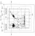
図5は、第1実施形態に係る情報処理装置400での表示例を示す図である。図5には、前述のステップS100からステップS112の実行中に表示装置410に表示される画像GUが示される。
5 is a diagram showing a display example of the
図5に示すように、画像GUは、領域R1~R9を含む。以下、図5に基づいて、領域R1~R9を順に簡単に説明する。 As shown in FIG. 5, image GU includes regions R1 to R9. Below, we will briefly explain regions R1 to R9 in order based on FIG. 5.
領域R1は、複数の情報DCの入力を受け付けるための領域である。図5に示す例では、領域R1がドロップダウンリストG1aとボタンG1bとを含む。ドロップダウンリストG1aは、サーバー等の外部装置に記憶された複数の情報DCを選択するための要素である。ボタンG1bは、ドロップダウンリストG1aで選択された複数の情報DCを情報処理装置400に読み込ませることを受け付けるための要素である。前述のステップS101では、このように情報処理装置400に読み込まれた複数の情報DCを取得部441が取得する。
Area R1 is an area for accepting input of multiple pieces of information DC. In the example shown in FIG. 5, area R1 includes a drop-down list G1a and a button G1b. The drop-down list G1a is an element for selecting multiple pieces of information DC stored in an external device such as a server. The button G1b is an element for accepting that the multiple pieces of information DC selected in the drop-down list G1a be loaded into the
領域R2は、第1軸AX1および第2軸AX2のそれぞれに対応付ける情報DCを選択するための領域である。図5に示す例では、領域R2がドロップダウンリストG2a、G2bを含む。ドロップダウンリストG2aは、読み込んだ複数の情報DCから第1軸AX1に対応付ける任意の1つの情報DCを選択するための要素である。前述のステップS102では、第1受付部442が、ドロップダウンリストG2aでの選択結果に基づいて、第1軸AX1に対応付ける情報DCの入力の有無を判断し、当該入力がある場合(ステップS102:YES)、第1軸AX1に対応付ける情報DCの入力を受け付ける。ドロップダウンリストG2bは、読み込んだ複数の情報DCから第2軸AX2に対応付ける任意の1つの情報DCを選択するための要素である。前述のステップS104では、第1受付部442が、ドロップダウンリストG2bでの選択結果に基づいて、第2軸AX2に対応付ける情報DCの入力の有無を判断し、当該入力がある場合(ステップS104:YES)、第2軸AX2に対応付ける情報DCの入力を受け付ける。
The area R2 is an area for selecting information DC to be associated with each of the first axis AX1 and the second axis AX2. In the example shown in FIG. 5, the area R2 includes drop-down lists G2a and G2b. The drop-down list G2a is an element for selecting any one of the information DCs to be associated with the first axis AX1 from the multiple pieces of information DC that have been read. In the above-mentioned step S102, the
領域R3は、第1軸AX1および第2軸AX2のそれぞれに情報DCを対応付けた状態で、駆動波形PDの候補に対応する表示を行うための領域である。領域R3には、第1軸AX1を縦軸とし、第2軸AX2を横軸とするグラフが表示される。ここで、領域R3には、第1軸AX1および第2軸AX2との対応付けのもとで、駆動波形PDの候補を示す複数のドットDtが表示される。前述のステップS103、S105では、第1表示部445が、領域R2、R4、R5、R6、R7に対する入力結果に基づいて、複数のドットDtを表示させる。ここで、領域R3に表示されている各ドットDtを選択する(カーソルを合わせる)と、そのドットDtに対応する駆動波形PDにおける後述する各評価情報が表示される。図5に示す例では、領域R3に表示される複数のドットDtのうち、複数の駆動波形PDの候補のパレート最適解となるドットDtであるドットDtaは、他のドットDtと異なる態様で表示される。また、領域R3には、複数のドットDtaを繋げた折れ線である線LNが表示される。線LNは、複数の駆動波形PDの候補のパレートフロントを示す。
The region R3 is a region for displaying candidates for the drive waveform PD in a state where information DC is associated with each of the first axis AX1 and the second axis AX2. A graph with the first axis AX1 as the vertical axis and the second axis AX2 as the horizontal axis is displayed in the region R3. Here, in the region R3, a plurality of dots Dt indicating candidates for the drive waveform PD are displayed in association with the first axis AX1 and the second axis AX2. In the above-mentioned steps S103 and S105, the
領域R4は、領域R3における複数の駆動波形PDの候補の表示態様を選択するための領域である。図5に示す例では、領域R4がチェックボックスG4a、G4b、G4cを含む。チェックボックスG4aは、領域R3において複数の駆動波形PDの候補を散布図で表示するか否かを選択するための要素であり、選択された場合、前述のドットDtを表示させる。チェックボックスG4bは、領域R3において複数の駆動波形PDの候補を折れ線図で表示するか否かを選択するための要素である。チェックボックスG4cは、領域R3において複数の駆動波形PDの候補をすべて表示するか否かを選択するための要素であり、選択された場合、後述の領域R8で設定された条件を満たさない候補を含んでいても、すべての候補を表示させる。ただし、この場合、領域R8で設定された条件を満たさない候補は、他の候補と異なる態様で区別可能に表示される。 Region R4 is an area for selecting the display mode of multiple drive waveform PD candidates in region R3. In the example shown in FIG. 5, region R4 includes check boxes G4a, G4b, and G4c. Check box G4a is an element for selecting whether to display multiple drive waveform PD candidates in region R3 in a scatter diagram, and when selected, the above-mentioned dot Dt is displayed. Check box G4b is an element for selecting whether to display multiple drive waveform PD candidates in region R3 in a line diagram. Check box G4c is an element for selecting whether to display all multiple drive waveform PD candidates in region R3, and when selected, all candidates are displayed even if they do not satisfy the conditions set in region R8 described below. However, in this case, the candidates that do not satisfy the conditions set in region R8 are displayed in a manner different from other candidates so that they can be distinguished.
領域R5は、領域R3における複数の駆動波形PDの候補のパレート最適解の表示に関する設定のための領域である。第3受付部444は、領域R5に対する入力結果に基づいて、前述のステップS108においてパレート最適解の表示指示の有無を判断し、当該表示指示がある場合(ステップS108:YES)、ステップS109においてパレート最適解を算出する。図5に示す例では、領域R5がチェックボックスG5a、G5bを含む。チェックボックスG5aは、領域R3において複数の駆動波形PDの候補のパレート最適解を表示するか否かを選択するための要素であり、選択された場合、前述のドットDtaを表示させる。チェックボックスG5bは、領域R3において複数の駆動波形PDの候補のパレートフロントを表示するか否かを選択するための要素であり、選択された場合、前述の線LNを表示させる。
Region R5 is an area for setting the display of the Pareto optimal solutions of the multiple drive waveform PD candidates in region R3. Based on the input result for region R5, the
領域R6は、領域R3におけるパレート最適解の表示を行う場合の条件設定のための領域である。図5に示す例では、領域R6がドロップダウンリストG6aとボタンG6bとドロップダウンリストG6cとボタンG6dとを含む。ドロップダウンリストG6aは、第1軸AX1に対応付けられた情報DCをパレート最適解の変数として設定するための要素である。ボタンG6bは、ドロップダウンリストG6aで設定した変数についてパレート最適化の目的関数を最大化するか最小化するかを選択するための要素である。ドロップダウンリストG6cは、第2軸AX2に対応付けられた情報DCをパレート最適解の変数として設定するための要素である。ボタンG6dは、ドロップダウンリストG6cで設定した変数についてパレート最適化の目的関数を最大化するか最小化するかを選択するための要素である。 Area R6 is an area for setting conditions when displaying the Pareto optimal solutions in area R3. In the example shown in FIG. 5, area R6 includes a drop-down list G6a, a button G6b, a drop-down list G6c, and a button G6d. The drop-down list G6a is an element for setting information DC associated with the first axis AX1 as a variable of the Pareto optimal solution. The button G6b is an element for selecting whether to maximize or minimize the objective function of the Pareto optimization for the variable set in the drop-down list G6a. The drop-down list G6c is an element for setting information DC associated with the second axis AX2 as a variable of the Pareto optimal solution. The button G6d is an element for selecting whether to maximize or minimize the objective function of the Pareto optimization for the variable set in the drop-down list G6c.
領域R7は、領域R3に表示する駆動波形PDの候補の条件を設定するための領域である。第2受付部443は、前述のステップS106において、領域R7に対する入力結果に基づいて、情報DCの条件の入力の有無を判断する。図5に示す例では、領域R6がドロップダウンリストG7aと複数のスライダG7bとを含む。ドロップダウンリストG7aは、条件を設定する情報DCを選択するための要素である。複数のスライダG7bのそれぞれは、ドロップダウンリストG7aにより選択された情報DCの条件として上限値および下限値を設定するための要素である。本実施形態では、スライダG7bがドロップダウンリストG7aによる情報DCの選択ごとに出現する。図5に示す例ではスライダG7bとして吐出量Iw、第1収縮時間Pwd1、第1ホールド時間Pwh1の3つの情報DCが表示されているが、これは図5に示す例よりも前にドロップダウンリストG7aを介して上記3つの情報DCが選択されたことを意味する。また、本実施形態では、スライダG7bが1対のスライダを含む。当該1対のスライダのうち、一方が上限値を設定するためのスライダであり、他方が下限値を設定するためのスライダである。ここで、上限値が最大値でなく、かつ、下限値が最小値でない場合、当該1対のスライダ間の部分に対する操作により、上限値と下限値との差分を維持しつつ、当該1対のスライダを移動させることが可能である。
Region R7 is an area for setting the conditions of the candidate drive waveform PD to be displayed in region R3. In the above-mentioned step S106, the
領域R8は、複数の駆動波形PDの候補について任意の1以上の情報DCの内容を表示するための領域である。図5に示す例では、領域R8が選択部G8aと表示部G8bとを含む。選択部G8aは、複数の情報DCのうち任意の1以上の情報DCを選択するための要素である。表示部G8bは、選択部G8aで選択された1以上の情報DCを駆動波形PDの候補ごとに並べて表示するための領域である。領域R8の使用例は、後に図13に基づいて説明する。 Area R8 is an area for displaying the contents of any one or more pieces of information DC for multiple drive waveform PD candidates. In the example shown in FIG. 5, area R8 includes a selection section G8a and a display section G8b. Selection section G8a is an element for selecting any one or more pieces of information DC from the multiple pieces of information DC. Display section G8b is an area for displaying one or more pieces of information DC selected in selection section G8a in a row for each drive waveform PD candidate. An example of the use of area R8 will be described later with reference to FIG. 13.
領域R9は、複数の駆動波形PDの候補について任意の1以上の情報DCについて、情報DCがテーブルおよびプロットで表示できない画像データ、テキストデータまたは波形データ等である場合、情報DCの内容を表示するための領域である。図5に示す例では、領域R9が選択部G9aと表示部G9bとを含む。選択部G9aは、複数の情報DCのうち任意の1以上の情報DCを選択するための要素である。表示部G9bは、選択部G9aで選択された1以上の情報DCを示す画像、テキストまたは波形等を表示するための領域である。 Region R9 is an area for displaying the contents of information DC for any one or more information DC for multiple drive waveform PD candidates, when the information DC is image data, text data, waveform data, etc. that cannot be displayed in a table and plot. In the example shown in FIG. 5, region R9 includes a selection section G9a and a display section G9b. Selection section G9a is an element for selecting any one or more information DC from the multiple information DC. Display section G9b is an area for displaying an image, text, waveform, etc. indicating one or more information DC selected in selection section G9a.
以上のような画像GUは、第1軸AX1および第2軸AX2のそれぞれにユーザーからの入力に応じた情報DCを対応付けた状態で、複数の駆動波形PDの候補に対応する表示を行う。以下、図6から図19に基づいて、画像GUの使用例を説明する。 The image GU described above displays multiple drive waveform PD candidates with information DC corresponding to user input associated with each of the first axis AX1 and the second axis AX2. Below, examples of using the image GU are described with reference to Figures 6 to 19.
図6は、第1評価情報および第2評価情報の表示例を示す図である。図6では、第1軸AX1に第1評価情報として吐出速度Vmを示す情報DCを対応付けるとともに、第2軸AX2に第2評価情報として最高電位Vhを示す情報DCを対応付けた場合が例示される。 Figure 6 is a diagram showing an example of displaying the first evaluation information and the second evaluation information. In Figure 6, an example is shown in which information DC indicating the discharge speed Vm is associated with the first axis AX1 as the first evaluation information, and information DC indicating the maximum potential Vh is associated with the second axis AX2 as the second evaluation information.
ここで、領域R2のドロップダウンリストG2aを用いて、吐出速度Vmを示す情報DCが選択されるとともに、領域R2のドロップダウンリストG2bを用いて、最高電位Vhを示す情報DCが選択される。これにより、第1受付部442は、第1軸AX1に複数の情報DCのうちの第1評価情報として吐出速度Vmを示す情報DCを対応付け、第2軸AX2に複数の情報DCのうちの第2評価情報として最高電位Vhを示す情報DCを対応付けることについてのユーザーの入力を受け付ける。
Here, the information DC indicating the discharge speed Vm is selected using the drop-down list G2a in region R2, and the information DC indicating the maximum potential Vh is selected using the drop-down list G2b in region R2. As a result, the
図6に示す例では、領域R3に、第1軸AX1に第1評価情報として吐出速度Vmを示す情報DCを対応付けるとともに、第2軸AX2に第2評価情報として最高電位Vhを示す情報DCを対応付けた状態で、複数の駆動波形PDの候補に対応関係を示すグラフが表示される。 In the example shown in FIG. 6, a graph showing the correspondence between multiple drive waveform PD candidates is displayed in region R3, with information DC indicating the discharge speed Vm corresponding to the first axis AX1 as the first evaluation information, and information DC indicating the maximum potential Vh corresponding to the second axis AX2 as the second evaluation information.
ここで、図6に示す例では、領域R4において、チェックボックスG4a、G4b、G4cのうちチェックボックスG4aのみが選択される。このため、領域R3には、複数の駆動波形PDの候補に対応する表示として、各候補の吐出速度Vmと最高電位Vhとの関係を示すドットDtが表示される。 Here, in the example shown in FIG. 6, in region R4, only check box G4a is selected among check boxes G4a, G4b, and G4c. Therefore, in region R3, dots Dt are displayed that indicate the relationship between the ejection speed Vm and maximum potential Vh of each candidate as an indication corresponding to multiple drive waveform PD candidates.
また、図6に示す例では、領域R5において、チェックボックスG5a、G5bのうちチェックボックスG5a、G5bの両方が選択される。これにより、第3受付部444は、第1表示部445にパレート最適解情報を表示させるか否かについてのユーザーの選択と、を受け付ける。そして、第1表示部445は、第1評価情報と第2評価情報のパレート最適解に関するパレート最適解情報を表示する。ここで、領域R3には、複数の駆動波形PDの候補のパレート最適解を示す複数のドットDtaが他のドットDtと区別可能な態様で表示されるとともに、複数の駆動波形PDの候補のパレートフロントを示す線LNが表示される。
In the example shown in FIG. 6, both check boxes G5a and G5b are selected in region R5. This causes the
このように、第1表示部445は、パレート最適解情報として、駆動波形PDの候補を示すプロットのうちパレート最適解となるプロットを他のプロットと識別可能なようにして表示する。また、第1表示部445は、パレート最適解情報として、駆動波形PDの候補を示すプロットのうちパレート最適解に対応するラインとして線LNを表示する。なお、図6では、作図の便宜上、ドットDtが白抜きのドットで示されるとともに、ドットDtaが黒塗りのドットで示される。
In this way, the
さらに、図6に示す例では、領域R6において、ドロップダウンリストG6aに最高電位Vhが入力され、ボタンG6bに最小化が選択され、ドロップダウンリストG6cに吐出速度Vmが入力され、ボタンG6bに最大化が選択される。これにより、第3受付部444は、パレート最適解を得る際に第1評価情報が示す値が大きいことを目的とするか小さいことを目的とするかについてのユーザーの選択を受け付ける。ここで、領域R3に表示される複数のドットDtaは、吐出速度Vmおよび最高電位Vhを変数とする目的関数について、最高電位Vhが最小化されるとともに吐出速度Vmが最大化されるパレート最適解を示す。
Furthermore, in the example shown in FIG. 6, in region R6, the maximum potential Vh is input into drop-down list G6a, minimize is selected in button G6b, ejection speed Vm is input into drop-down list G6c, and maximize is selected in button G6b. This allows the
なお、図6に示す例では、ドロップダウンリストG2aとドロップダウンリストG6cに同じ評価情報である吐出速度Vmが、ドロップダウンリストG2bとドロップダウンリストG6aに同じ評価情報である最高電位Vhが、それぞれ入力されている。言い換えると、第1軸AX1と第2軸AX2の組合せと、パレート最適解情報の2変数の組合せとが一致している。そのため、領域R3に表示されるドットDtと、パレート最適解に対応するドットDtaや線LNとには、左上のドットDtが選択されるという関係がわかり易く表示されることになる。但し、ドロップダウンリストG2aとドロップダウンリストG6cに異なる評価情報を入力しても良いし、ドロップダウンリストG2bとドロップダウンリストG6aに異なる評価情報を入力しても良い。これらの場合のようにドロップダウンリストG6aやドロップダウンリストG6cに入力される情報を第1パレート変数情報や第2パレート変数情報とも称する。なお、その場合、領域R3に表示されるドットDtと、パレート最適解に対応するドットDtaや線LNとには、一見して相関性がわからないような表示がなされる可能性があるが、ユーザーによってはそのような表示形態を所望する場合もある。 In the example shown in FIG. 6, the drop-down list G2a and the drop-down list G6c are input with the same evaluation information, the discharge speed Vm, and the drop-down list G2b and the drop-down list G6a are input with the same evaluation information, the maximum potential Vh. In other words, the combination of the first axis AX1 and the second axis AX2 matches the combination of two variables of the Pareto optimal solution information. Therefore, the relationship that the upper left dot Dt is selected is displayed in an easy-to-understand manner between the dot Dt displayed in the region R3 and the dot Dta and the line LN corresponding to the Pareto optimal solution. However, different evaluation information may be input into the drop-down list G2a and the drop-down list G6c, or different evaluation information may be input into the drop-down list G2b and the drop-down list G6a. In these cases, the information input into the drop-down list G6a and the drop-down list G6c is also referred to as the first Pareto variable information and the second Pareto variable information. In this case, the dots Dt displayed in region R3 and the dots Dta and lines LN corresponding to the Pareto optimal solutions may be displayed in such a way that their correlation is not immediately apparent, but some users may prefer this display format.
なお、図6に示す例では、領域R7、R8、R9に対する入力が行われない。このため、領域R7に対する入力が行われないことにより、領域R3には、複数の駆動波形PDの候補のすべてに対応するドットDtが表示される。また、領域R8に対する入力が行われないことにより、領域R8の表示部G8bには、データが表示されない。領域R9に対する入力が行われないことにより、領域R9の表示部G9bには、データが表示されない。 In the example shown in FIG. 6, no input is made to regions R7, R8, and R9. Therefore, since no input is made to region R7, dots Dt corresponding to all of the multiple drive waveform PD candidates are displayed in region R3. Furthermore, since no input is made to region R8, no data is displayed in the display section G8b of region R8. Since no input is made to region R9, no data is displayed in the display section G9b of region R9.
図7は、第1評価情報および第3評価情報の表示例を示す図である。図7では、前述の図6に示す状態における画像GUの領域R2のドロップダウンリストG2bに入力状態を最高電位Vhから第1収縮時間Pwd1に変更した場合が例示される。すなわち、図7では、第1軸AX1に第1評価情報として吐出速度Vmを示す情報DCを対応付けるとともに、第2軸AX2に第3評価情報として第1収縮時間Pwd1を示す情報DCを対応付けた場合が例示される。 Figure 7 is a diagram showing an example of the display of the first evaluation information and the third evaluation information. Figure 7 illustrates an example in which the input state in the drop-down list G2b of the region R2 of the image GU in the state shown in Figure 6 described above is changed from the maximum potential Vh to the first contraction time Pwd1. That is, Figure 7 illustrates an example in which information DC indicating the discharge speed Vm is associated with the first axis AX1 as the first evaluation information, and information DC indicating the first contraction time Pwd1 is associated with the second axis AX2 as the third evaluation information.
ここで、領域R2のドロップダウンリストG2aを用いて、吐出速度Vmを示す情報DCが選択されるとともに、領域R2のドロップダウンリストG2bを用いて、第1収縮時間Pwd1を示す情報DCが選択される。これにより、第1受付部442は、第2軸AX2に、第2評価情報としての情報DCから複数の情報DCのうちの第3評価情報としての情報DCに切り替えて対応付けることについてのユーザーの入力を更に受け付ける。
Here, the information DC indicating the discharge speed Vm is selected using the drop-down list G2a in region R2, and the information DC indicating the first contraction time Pwd1 is selected using the drop-down list G2b in region R2. This causes the
図7に示す例では、領域R3に、第1軸AX1に第1評価情報として吐出速度Vmを示す情報DCを対応付けるとともに、第2軸AX2に第3評価情報として第1収縮時間Pwd1を示す情報DCを対応付けた状態で、複数の駆動波形PDの候補に対応関係を示すグラフが表示される。 In the example shown in FIG. 7, a graph showing the correspondence between multiple candidates for the drive waveform PD is displayed in region R3, with information DC indicating the discharge speed Vm corresponding to the first axis AX1 as the first evaluation information, and information DC indicating the first contraction time Pwd1 corresponding to the second axis AX2 as the third evaluation information.
なお、図7に示す例では、領域R4、R5、R6、R7、R8、R9に対する入力状態が前述の図6に示す例と同じである。 In the example shown in Figure 7, the input state for regions R4, R5, R6, R7, R8, and R9 is the same as the example shown in Figure 6 above.
以上のように、第2軸AX2に対応付ける情報DCを変更することができる。なお、図7では、第2軸AX2に対応付ける情報DCを変更する態様が例示されるが、図6に示す状態における画像GUの領域R2のドロップダウンリストG2aに入力状態を変更した場合、第1軸AX1に第3評価情報として変更後の情報DCが対応付けられる。 As described above, the information DC associated with the second axis AX2 can be changed. Note that FIG. 7 illustrates an example of changing the information DC associated with the second axis AX2, but if the input state is changed in the drop-down list G2a in the area R2 of the image GU in the state shown in FIG. 6, the changed information DC is associated with the first axis AX1 as the third evaluation information.
図8は、パレート最適解の目的変更を行った場合の表示例を示す図である。図8では、前述の図6に示す状態における画像GUの領域R6のボタンG6bの入力状態を最小化から最大化に変更した場合が例示される。 Figure 8 shows an example of a display when the objective of the Pareto optimal solution is changed. Figure 8 shows an example of a case where the input state of button G6b in region R6 of image GU in the state shown in Figure 6 described above is changed from minimize to maximize.
図8に示す例では、領域R2、R4、R5、R7、R8、R9に対する入力状態が前述の図6に示す例と同じである。このため、図8では、前述の図6と同様、第1軸AX1に第1評価情報として吐出速度Vmを示す情報DCが対応付けられるとともに、第2軸AX2に第2評価情報として最高電位Vhを示す情報DCが対応付けられる。 In the example shown in FIG. 8, the input state for regions R2, R4, R5, R7, R8, and R9 is the same as the example shown in FIG. 6 described above. Therefore, in FIG. 8, similar to FIG. 6 described above, information DC indicating the discharge speed Vm is associated with the first axis AX1 as the first evaluation information, and information DC indicating the maximum potential Vh is associated with the second axis AX2 as the second evaluation information.
ここで、図8に示す例では、領域R6において、ボタンG6bに最大化が選択され、ドロップダウンリストG6aに最高電位Vhが入力され、ドロップダウンリストG6cに吐出速度Vmが入力され、ボタンG6bに最大化が選択される。このため、領域R3に表示される複数のドットDtaは、吐出速度Vmおよび最高電位Vhを変数とする目的関数について、最高電位Vhおよび吐出速度Vmがともに最大化されるパレート最適解を示す。また、線LNが当該パレート最適解のパレートフロントを示す。 In the example shown in FIG. 8, in region R6, maximize is selected in button G6b, maximum potential Vh is input in drop-down list G6a, ejection speed Vm is input in drop-down list G6c, and maximize is selected in button G6b. Therefore, the multiple dots Dta displayed in region R3 indicate the Pareto optimal solution in which the maximum potential Vh and ejection speed Vm are both maximized for the objective function with ejection speed Vm and maximum potential Vh as variables. Also, line LN indicates the Pareto front of the Pareto optimal solution.
以上のように、パレート最適解の条件を変更して即時に表示させることができる。 As shown above, you can change the conditions for the Pareto optimal solution and display it instantly.
図9は、第1条件情報の入力を受け付けた場合の表示例を示す図である。図9では、前述の図6に示す状態における画像GUの領域R7のドロップダウンリストG6cに吐出量Iwが入力されることにより、吐出量Iwを示す情報DCが第1条件情報として選択される場合が例示される。 Figure 9 is a diagram showing an example of a display when input of the first condition information is accepted. Figure 9 shows an example of a case where the discharge amount Iw is input into the drop-down list G6c of the region R7 of the image GU in the state shown in Figure 6 described above, and information DC indicating the discharge amount Iw is selected as the first condition information.
図9に示す例では、領域R2、R4、R5、R6、R8、R9に対する入力状態が前述の図6に示す例と同じである。このため、図9では、前述の図6と同様、第1軸AX1に第1評価情報として吐出速度Vmを示す情報DCが対応付けられるとともに、第2軸AX2に第2評価情報として最高電位Vhを示す情報DCが対応付けられる。 In the example shown in FIG. 9, the input state for regions R2, R4, R5, R6, R8, and R9 is the same as the example shown in FIG. 6 described above. Therefore, in FIG. 9, similar to FIG. 6 described above, information DC indicating the discharge speed Vm is associated with the first axis AX1 as the first evaluation information, and information DC indicating the maximum potential Vh is associated with the second axis AX2 as the second evaluation information.
ここで、図9に示す例では、領域R7において、ドロップダウンリストG6cに吐出量Iwが入力されることにより、吐出量Iwの上限値および下限値の条件を設定するためのスライダG7bが出現する。ここで、吐出量Iwの上限値が最大値に設定されるとともに、吐出量Iwの下限値が最小値に設定される。このため、図9に示す例では、領域R3の表示内容が前述の図6に示す例と同じである。 In the example shown in FIG. 9, when the discharge volume Iw is input into the drop-down list G6c in region R7, a slider G7b appears for setting the upper and lower limit conditions of the discharge volume Iw. Here, the upper limit of the discharge volume Iw is set to the maximum value, and the lower limit of the discharge volume Iw is set to the minimum value. For this reason, in the example shown in FIG. 9, the display content of region R3 is the same as the example shown in FIG. 6 described above.
以上のように、第1条件情報が設定される場合、第1表示部445は、第1軸AX1に複数の情報DCのうちの第1評価情報を、第1軸AX1と交差する第2軸AX2に複数の情報DCのうちの第2評価情報を、それぞれ対応付けた上で、第1条件情報が示す条件を満たす駆動波形PDの候補に対応する表示を行う。
When the first condition information is set as described above, the
図10は、第1条件情報に対するユーザーの条件の指定を説明するための図である。図10では、前述の図9に示す状態における画像GUの領域R7のスライダG7bが操作されることにより、第1条件情報として吐出量Iwを示す情報DCの条件が指定される場合が例示される。 Figure 10 is a diagram for explaining the user's specification of conditions for the first condition information. Figure 10 illustrates an example in which the slider G7b in the region R7 of the image GU in the state shown in Figure 9 described above is operated to specify a condition for information DC indicating the discharge volume Iw as the first condition information.
図10に示す例では、領域R2、R4、R5、R7、R8、R9に対する入力状態が前述の図9に示す例と同じである。このため、図10では、前述の図6と同様、第1軸AX1に第1評価情報として吐出速度Vmを示す情報DCが対応付けられるとともに、第2軸AX2に第2評価情報として最高電位Vhを示す情報DCが対応付けられる。 In the example shown in FIG. 10, the input state for regions R2, R4, R5, R7, R8, and R9 is the same as the example shown in FIG. 9 described above. Therefore, in FIG. 10, similar to FIG. 6 described above, information DC indicating the discharge speed Vm is associated with the first axis AX1 as the first evaluation information, and information DC indicating the maximum potential Vh is associated with the second axis AX2 as the second evaluation information.
ここで、図10に示す例では、領域R7において、スライダG7bの上限値と下限値との差分が図9に示す例よりも小さい。これにより、第2受付部443は、ユーザーによる第1条件情報に対する上限値と下限値の指定を受け付けることにより、複数の情報DCのうちの第1条件情報についてのユーザーの入力を受け付ける。このため、図10に示す例では、図9に示す複数のドットDtのうち、スライダG7bによる条件を満たさないドットDtが表示されず、スライダG7bによる条件を満たすドットDtが表示される。
Here, in the example shown in FIG. 10, in region R7, the difference between the upper and lower limit values of slider G7b is smaller than in the example shown in FIG. 9. As a result, the
以上のように、第2受付部443は、第1条件情報に対するユーザーの条件の指定をスライダによって受け付ける。これにより、第1条件情報の条件をユーザーにより指定し、その指定結果に基づいて領域R3の表示を変更することができる。また、第1表示部445は、第2受付部443に対する第1条件情報についてのユーザーの入力に追従して表示する第1評価情報と第2評価情報を切り替える。
As described above, the
なお図9と図10からわかるように本実施形態によればスライダG7bが操作されることによってドットDtの表示が変わることにリアルタイムで連動して線LNの表示も変わる。 As can be seen from Figures 9 and 10, in this embodiment, when the slider G7b is operated, the display of the dot Dt changes, and the display of the line LN also changes in real time.
図11は、第2条件情報の入力を受け付けた場合の表示例を示す図である。図11では、前述の図10に示す状態における画像GUの領域R7のドロップダウンリストG6cに第1収縮時間Pwd1および第1ホールド時間Pwh1が追加入力されることにより、第1収縮時間Pwd1を示す情報DCが第2条件情報として選択されるとともに、第1ホールド時間Pwh1を示す情報DCが第3条件情報として選択される場合が例示される。 Figure 11 is a diagram showing an example of a display when input of second condition information is accepted. Figure 11 illustrates a case where the first contraction time Pwd1 and the first hold time Pwh1 are additionally input into the drop-down list G6c of the region R7 of the image GU in the state shown in Figure 10 described above, whereby information DC indicating the first contraction time Pwd1 is selected as the second condition information and information DC indicating the first hold time Pwh1 is selected as the third condition information.
図11に示す例では、領域R2、R4、R5、R6、R8、R9に対する入力状態が前述の図6に示す例と同じである。このため、図11では、前述の図6と同様、第1軸AX1に第1評価情報として吐出速度Vmを示す情報DCが対応付けられるとともに、第2軸AX2に第2評価情報として最高電位Vhを示す情報DCが対応付けられる。 In the example shown in FIG. 11, the input state for regions R2, R4, R5, R6, R8, and R9 is the same as the example shown in FIG. 6 described above. Therefore, in FIG. 11, similar to FIG. 6 described above, information DC indicating the discharge speed Vm is associated with the first axis AX1 as the first evaluation information, and information DC indicating the maximum potential Vh is associated with the second axis AX2 as the second evaluation information.
ここで、図11に示す例では、領域R7において、ドロップダウンリストG6cに第1収縮時間Pwd1および第1ホールド時間Pwh1が追加入力されることにより、吐出量Iwの条件を設定するためのスライダG7bのほか、第1収縮時間Pwd1の条件を設定するためのスライダG7bと、第1ホールド時間Pwh1の条件を設定するためのスライダG7bと、が出現する。ここで、各スライダG7bの上限値と下限値との差分が最大範囲よりも小さい。このため、図11に示す例では、図9に示す複数のドットDtのうち、これらスライダG7bによる条件を満たさないドットDtが表示されず、これらスライダG7bによる条件を満たすドットDtが表示される。 In the example shown in FIG. 11, in region R7, the first contraction time Pwd1 and the first hold time Pwh1 are additionally input into the drop-down list G6c, and in addition to the slider G7b for setting the conditions for the discharge volume Iw, a slider G7b for setting the conditions for the first contraction time Pwd1 and a slider G7b for setting the conditions for the first hold time Pwh1 appear. Here, the difference between the upper and lower limits of each slider G7b is smaller than the maximum range. For this reason, in the example shown in FIG. 11, of the multiple dots Dt shown in FIG. 9, dots Dt that do not satisfy the conditions set by these sliders G7b are not displayed, and dots Dt that satisfy the conditions set by these sliders G7b are displayed.
以上のように、第1条件情報、第2条件情報および第3条件情報の条件をユーザーにより指定し、その指定結果に基づいて領域R3の表示を変更することができる。このように、第1条件情報および第2条件情報が設定される場合、第1表示部445は、第1条件情報が示す条件と第2条件情報が示す条件の両方を満たす駆動波形PDに対応する表示を行う。
As described above, the user can specify the conditions of the first condition information, the second condition information, and the third condition information, and change the display of region R3 based on the result of the specification. In this way, when the first condition information and the second condition information are set, the
図12は、第1受付部442による第1軸AX1および第2軸AX2に対する情報DCの対応付けの入力を説明するための図である。図12では、領域R2のドロップダウンリストG2aに対する入力状態が例示される。
Figure 12 is a diagram for explaining the input of the correspondence of information DC to the first axis AX1 and the second axis AX2 by the
図12に示すように、ドロップダウンリストG2aに対してクリック等の操作が行われると、第1軸AX1に対応付けることが可能な情報DCのリストが表示される。図12に示す例では、当該リストに識別子ID、試行順番Iter、中間電位Vc、最高電位Vh、第1収縮時間Pwd1、第1ホールド時間Pwh1、第1膨張時間Pwc1、第2ホールド時間Pwh2、第2収縮時間Pwd2、吐出量Iw、吐出速度Vmおよび目的関数f(x)の項目が含まれる。これらの項目のうちから1つの項目がクリック等の操作により選択される。第1受付部442は、この入力結果に基づいて、第1軸AX1に対して複数の情報DCのうちの任意の1つの情報DCを対応付ける入力を行う。
As shown in FIG. 12, when an operation such as clicking is performed on the drop-down list G2a, a list of information DC that can be associated with the first axis AX1 is displayed. In the example shown in FIG. 12, the list includes the following items: identifier ID, trial order Iter, intermediate potential Vc, highest potential Vh, first contraction time Pwd1, first hold time Pwh1, first expansion time Pwc1, second hold time Pwh2, second contraction time Pwd2, discharge volume Iw, discharge speed Vm, and objective function f(x). One of these items is selected by an operation such as clicking. Based on this input result, the
なお、識別子IDは、複数の情報DCを互いに識別するための情報であり、情報DCごとに対応する。目的関数f(x)は、領域R6に対する入力に基づくパレート最適化の目的関数である。 The identifier ID is information for identifying multiple pieces of information DC from one another, and corresponds to each piece of information DC. The objective function f(x) is an objective function of Pareto optimization based on the input to region R6.
以上のように、ドロップダウンリストG2aを用いて、第1軸AX1に対して複数の情報DCのうちの任意の1つの情報DCを対応付ける入力を行うことができる。なお、図示しないが、ドロップダウンリストG2bに対してクリック等の操作が行われると、前述のリストと同様のリストが表示される。そして、第1受付部442は、ドロップダウンリストG2bに対する入力結果に基づいて、第2軸AX2に対して複数の情報DCのうちの任意の1つの情報DCを対応付ける入力を行う。
As described above, the drop-down list G2a can be used to input data to associate any one of the multiple pieces of information DC with the first axis AX1. Although not shown, when an operation such as clicking is performed on the drop-down list G2b, a list similar to the above-mentioned list is displayed. Then, the
図13は、情報DCの詳細表示の一例を示す図である。図13では、領域R8の選択部G8aに吐出量Iwが入力された場合が例示される。 Figure 13 is a diagram showing an example of a detailed display of information DC. Figure 13 shows an example in which the discharge volume Iw is input into the selection section G8a of region R8.
図13に示すように、選択部G8aに吐出量Iwが入力されると、表示部G8bには、選択部G8aで選択された情報DCとして吐出量Iwの情報が駆動波形PDの候補ごとに表示される。 As shown in FIG. 13, when the discharge volume Iw is input to the selection section G8a, the display section G8b displays information on the discharge volume Iw for each candidate drive waveform PD as information DC selected in the selection section G8a.
なお、図示しないが、選択部G8aに複数の情報DCが入力されると、表示部G8bには、選択部G8aで選択された複数の情報DCが駆動波形PDの候補ごとに並べて表示される。 Although not shown, when multiple pieces of information DC are input to the selection unit G8a, the multiple pieces of information DC selected by the selection unit G8a are displayed on the display unit G8b in a row for each candidate driving waveform PD.
図14は、第1軸AX1および第2軸AX2のそれぞれに他の情報DCを対応付けた場合の表示例を示す図である。図14では、第1軸AX1に第1評価情報として吐出量Iwを示す情報DCを対応付けるとともに、第2軸AX2に第2評価情報として試行順番Iterを示す情報DCを対応付けた場合が例示される。ここで、領域R2のドロップダウンリストG2aは、吐出量Iwを示す情報DCが選択されたことを表示する。領域R2のドロップダウンリストG2bは、試行順番Iterを示す情報DCが選択されたことを表示する。 Figure 14 is a diagram showing a display example in which other information DC is associated with each of the first axis AX1 and the second axis AX2. Figure 14 illustrates an example in which information DC indicating the discharge amount Iw is associated with the first axis AX1 as the first evaluation information, and information DC indicating the trial order Iter is associated with the second axis AX2 as the second evaluation information. Here, the drop-down list G2a in region R2 indicates that information DC indicating the discharge amount Iw has been selected. The drop-down list G2b in region R2 indicates that information DC indicating the trial order Iter has been selected.
図14に示す例では、領域R3に、第1軸AX1に第1評価情報として吐出量Iwを示す情報DCを対応付けるとともに、第2軸AX2に第2評価情報として試行順番Iterを示す情報DCを対応付けた状態で、複数の駆動波形PDの候補に対応関係を示すグラフが表示される。 In the example shown in FIG. 14, a graph showing the correspondence between multiple candidates for drive waveforms PD is displayed in region R3, with information DC indicating the discharge volume Iw corresponding to the first axis AX1 as the first evaluation information, and information DC indicating the trial order Iter corresponding to the second axis AX2 as the second evaluation information.
駆動波形PDの探索過程では、試行順番Iterに応じた複数の駆動波形PDの候補が得られる。ここで、駆動波形PDの探索過程では、一般に、吐出特性が目的値に近づくように、複数の駆動波形PDの候補が液体吐出ヘッド210に選択的に順次印加される。このため、試行順番Iterが大きいほど、駆動波形PDの候補に対応する情報DCの信頼性が高くなる。
In the drive waveform PD search process, multiple drive waveform PD candidates are obtained according to the trial order Iter. In the drive waveform PD search process, multiple drive waveform PD candidates are generally selectively applied to the
したがって、図14に示す例では、領域R3において、試行順番Iterが大きくなるに従って、吐出量Iwが収束しており、前述のような駆動波形PDの探索が行われたことがわかる。 Therefore, in the example shown in Figure 14, in region R3, as the trial order Iter increases, the discharge volume Iw converges, and it can be seen that a search for the drive waveform PD was performed as described above.
ここで、図14に示す例では、領域R4において、チェックボックスG4a、G4b、G4cのうちチェックボックスG4a、G4cが選択される。このため、チェックボックスG4aが選択されることにより、領域R3には、複数の駆動波形PDの候補に対応する表示として、各候補の吐出量Iwと試行順番Iterとの関係を示すドットDtが表示される。また、チェックボックスG4cが選択されることにより、領域R3には、領域R7での入力の有無に関わらず、複数の駆動波形PDの候補のすべてに対応するドットDtが表示される。ただし、領域R7で設定された条件を満たすドットDtと当該条件を満たさないドットDtとが区別可能に表示される。なお、図14では、作図の都合上、当該条件を満たさないドットDtが白抜きのドットで示されるとともに、当該条件を満たすドットDtが黒塗りのドットで示される。 Here, in the example shown in FIG. 14, check boxes G4a and G4c are selected from among check boxes G4a, G4b, and G4c in region R4. Therefore, by selecting check box G4a, dots Dt indicating the relationship between the discharge volume Iw and the trial order Iter of each candidate are displayed in region R3 as a display corresponding to the multiple drive waveform PD candidates. Also, by selecting check box G4c, dots Dt corresponding to all of the multiple drive waveform PD candidates are displayed in region R3, regardless of whether or not there is an input in region R7. However, dots Dt that satisfy the conditions set in region R7 and dots Dt that do not satisfy the conditions are displayed in a distinguishable manner. Note that in FIG. 14, for convenience of drawing, dots Dt that do not satisfy the conditions are shown as open dots, and dots Dt that satisfy the conditions are shown as filled dots.
このように、第1条件情報が示す条件を満たす駆動波形PDの候補に対応する表示と、第1条件情報が示す条件を満たさない駆動波形PDの候補に対応する表示と、識別可能に表示させる。 In this way, the display corresponding to the candidate drive waveform PD that satisfies the condition indicated by the first condition information and the display corresponding to the candidate drive waveform PD that does not satisfy the condition indicated by the first condition information are displayed in a distinguishable manner.
図15は、第1軸AX1および第2軸AX2に対応付ける情報DCの入れ替えを説明するための図である。図15では、前述の図6に示す状態における画像GUの領域R2のドロップダウンリストG2aに入力状態を吐出速度Vmから最高電位Vhに変更するとともにドロップダウンリストG2bに入力状態を最高電位Vhから吐出速度Vmに変更した場合が例示される。すなわち、図15では、第1軸AX1に第2評価情報として最高電位Vhを示す情報DCを対応付けるとともに、第2軸AX2に第1評価情報として吐出速度Vmを示す情報DCを対応付けた場合が例示される。 Figure 15 is a diagram for explaining the interchange of information DC associated with the first axis AX1 and the second axis AX2. Figure 15 illustrates an example in which the input state of the drop-down list G2a of the region R2 of the image GU in the state shown in Figure 6 described above is changed from the ejection speed Vm to the maximum potential Vh, and the input state of the drop-down list G2b is changed from the maximum potential Vh to the ejection speed Vm. That is, Figure 15 illustrates an example in which information DC indicating the maximum potential Vh is associated with the first axis AX1 as the second evaluation information, and information DC indicating the ejection speed Vm is associated with the second axis AX2 as the first evaluation information.
ここで、領域R2のドロップダウンリストG2aを用いて、最高電位Vhを示す情報DCが選択されるとともに、領域R2のドロップダウンリストG2bを用いて、吐出速度Vmを示す情報DCが選択される。これにより、第1受付部442は、第1軸AX1に第1評価情報から第2評価情報に切り替えて対応付け、第2軸AX2に第2評価情報から第1評価情報に切り替えて対応付けることについてのユーザーの入力を受け付ける。
Here, the information DC indicating the maximum potential Vh is selected using the drop-down list G2a in region R2, and the information DC indicating the discharge velocity Vm is selected using the drop-down list G2b in region R2. This causes the
図15に示す例では、領域R3に、第1軸AX1に第2評価情報として最高電位Vhを示す情報DCを対応付けるとともに、第2軸AX2に第1評価情報として吐出速度Vmを示す情報DCを対応付けた状態で、複数の駆動波形PDの候補に対応関係を示すグラフが表示される。 In the example shown in FIG. 15, a graph showing the correspondence between multiple candidates for the drive waveform PD is displayed in region R3, with information DC indicating the maximum potential Vh as the second evaluation information corresponding to the first axis AX1, and information DC indicating the ejection speed Vm as the first evaluation information corresponding to the second axis AX2.
ここで、図15に示す例では、領域R4において、チェックボックスG4a、G4b、G4cのうちチェックボックスG4a、G4cが選択される。このため、チェックボックスG4aが選択されることにより、領域R3には、複数の駆動波形PDの候補に対応する表示として、各候補の最高電位Vhと吐出速度Vmとの関係を示すドットDtが表示される。また、チェックボックスG4cが選択されることにより、領域R3には、領域R7での入力の有無に関わらず、複数の駆動波形PDの候補のすべてに対応するドットDtが表示される。ただし、領域R7で設定された条件を満たすドットDtと当該条件を満たさないドットDtとが区別可能に表示される。なお、図15では、作図の都合上、当該条件を満たさないドットDtが白抜きのドットで示されるとともに、当該条件を満たすドットDtが黒塗りのドットで示される。 Here, in the example shown in FIG. 15, check boxes G4a and G4c are selected from among check boxes G4a, G4b, and G4c in region R4. Therefore, by selecting check box G4a, dots Dt showing the relationship between the maximum potential Vh and the ejection speed Vm of each candidate are displayed in region R3 as a display corresponding to the multiple drive waveform PD candidates. Also, by selecting check box G4c, dots Dt corresponding to all of the multiple drive waveform PD candidates are displayed in region R3 regardless of whether or not there is an input in region R7. However, dots Dt that satisfy the conditions set in region R7 and dots Dt that do not satisfy the conditions are displayed in a distinguishable manner. Note that in FIG. 15, for convenience of drawing, dots Dt that do not satisfy the conditions are shown as open dots, and dots Dt that satisfy the conditions are shown as filled dots.
図15に示す例では、領域R7において、最高電位Vh、試行順番Iter、吐出量Iwおよび第1膨張時間Pwc1の条件を設定するための複数のスライダG7bが表示される。ここで、図15に示すように、試行順番Iterの下限値を大きくすることにより、信頼性の高いドットDtが他のドットDtを区別可能に表示される。 In the example shown in FIG. 15, multiple sliders G7b are displayed in region R7 for setting the conditions of maximum potential Vh, trial order Iter, discharge volume Iw, and first expansion time Pwc1. Here, as shown in FIG. 15, by increasing the lower limit value of trial order Iter, highly reliable dots Dt are displayed so as to be distinguishable from other dots Dt.
図16および図17は、第1条件情報に対するユーザーの条件の指定を説明するための図である。図16および図17では、前述の図15に示す状態における画像GUの領域R7のスライダG7bの設定を変更した場合が例示される。 Figures 16 and 17 are diagrams for explaining the user's specification of conditions for the first condition information. Figures 16 and 17 show an example in which the setting of slider G7b of region R7 of image GU in the state shown in Figure 15 described above is changed.
図16に示す例では、領域R7の複数のスライダG7bのうち、最高電位Vhの条件を設定するためのスライダG7bが上限値と下限値との差分を小さくするように設定される。なお、他のスライダG7bは、上限値と下限値との差分が最大となるように設定される。 In the example shown in FIG. 16, among the multiple sliders G7b in region R7, the slider G7b for setting the condition for the highest potential Vh is set to reduce the difference between the upper limit value and the lower limit value. The other sliders G7b are set to maximize the difference between the upper limit value and the lower limit value.
ここで、最高電位Vhの条件を設定するためのスライダG7bに含まれる1対のスライダ間の部分に対する操作により、例えば、図17に示すように、上限値と下限値との差分を維持しつつ、当該1対のスライダを移動させることができる。また、このような操作に連動して、領域R3において、領域R7で設定された条件を満たすことを示すドットDtが変化する。 Here, by operating the portion between a pair of sliders included in slider G7b for setting the condition for the highest potential Vh, the pair of sliders can be moved while maintaining the difference between the upper limit value and the lower limit value, as shown in FIG. 17, for example. In addition, in conjunction with such an operation, the dot Dt in region R3, which indicates that the condition set in region R7 is satisfied, changes.
以上のように、第2受付部443は、ユーザーによる、第1条件情報に対する上限値と下限値の差分は固定しつつ、上限値と下限値の両方を連動して変化させるような指定を受け付ける。
As described above, the
図18および図19は、第1条件情報についてのユーザーの入力に追従したパレート最適解情報の表示の切り替えを説明するための図である。図18および図19では、前述の図15に示す状態における画像GUの領域R5のチェックボックスG5a、G5bの両方を選択した場合が例示される。 Figures 18 and 19 are diagrams for explaining the switching of the display of Pareto optimal solution information following the user's input for the first condition information. Figures 18 and 19 show an example in which both check boxes G5a and G5b in region R5 of image GU in the state shown in Figure 15 described above are selected.
図18に示す例では、領域R6において、ドロップダウンリストG6aに吐出速度Vmが入力され、ボタンG6bに最小化が選択され、ドロップダウンリストG6cに最高電位Vhが入力され、ボタンG6bに最大化が選択される。このため、領域R3に表示される複数のドットDtaは、吐出速度Vmおよび最高電位Vhを変数とする目的関数について、吐出速度Vmが最小化されるとともに最高電位Vhが最大化されるパレート最適解を示す。また、線LNが当該パレート最適解のパレートフロントを示す。 In the example shown in FIG. 18, in region R6, ejection speed Vm is input into drop-down list G6a, minimize is selected in button G6b, maximum potential Vh is input into drop-down list G6c, and maximize is selected in button G6b. Therefore, the multiple dots Dta displayed in region R3 indicate the Pareto optimal solutions in which ejection speed Vm is minimized and maximum potential Vh is maximized for an objective function with ejection speed Vm and maximum potential Vh as variables. In addition, line LN indicates the Pareto front of the Pareto optimal solutions.
ここで、図18に示す例では、領域R7のすべてのスライダG7bが最大範囲に設定される。この状態から、例えば、図19に示すように、吐出量Iwの条件を設定するためのスライダG7bに対する操作により、吐出量Iwの上限値と下限値との差分を小さくすると、これに連動して、領域R3において、領域R7で設定された条件満たすように、複数のドットDtaおよび線LNが変化する。 In the example shown in FIG. 18, all sliders G7b in region R7 are set to the maximum range. From this state, for example, as shown in FIG. 19, when the difference between the upper and lower limits of the discharge amount Iw is reduced by operating slider G7b for setting the conditions for the discharge amount Iw, the dots Dta and lines LN in region R3 change in response to this so as to satisfy the conditions set in region R7.
このように、第1表示部445は、第2受付部443が第1条件情報についてのユーザーの入力に追従して表示するパレート最適解情報を切り替える。
In this way, the
以上の情報処理装置400では、取得部441が複数の駆動波形PDの候補それぞれにおける互いに異なる複数の情報DCを取得するので、有用な資産となり得る過去の探索経過における各駆動波形PDの候補を利用することができる。そして、第1軸AX1に第1評価情報を対応付けるとともに、第2軸AX2に第2評価情報を対応付けることについて、第1受付部442がユーザーの入力を受け付けるので、複数の情報DCからユーザーの希望に応じた2つの情報を第1評価情報および第2評価情報として抽出することができる。また、これらの対応付けのもとで第1表示部445が駆動波形PDの候補に対応する表示を行うので、駆動波形PDの候補で得られる特性として第1評価情報と第2評価情報との関係をユーザーにわかりやすいように表示することができる。
In the above
本実施形態では、前述のように、第1受付部442は、第1軸AX1に、第1評価情報から複数の情報DCのうちの第3評価情報に切り替えて対応付けることについてのユーザーの入力を更に受け付ける。これにより、ユーザーに希望に応じて、第2評価情報と第3評価情報との関係を表示することができる。
In this embodiment, as described above, the
また、前述のように、第1受付部442は、第1軸AX1に第1評価情報から第2評価情報に切り替えて対応付け、第2軸AX2に第2評価情報から第1評価情報に切り替えて対応付けることについてのユーザーの入力を更に受け付ける。これにより、ユーザーに希望に応じて、第1軸AX1と第2軸AX2とを交換した態様で、第1評価情報と第2評価情報との関係を表示することができる。
As described above, the
さらに、前述のように、第1軸AX1に第1評価情報を対応付けるとともに、第2軸AX2に第2評価情報を対応付けたうえで、第1表示部445が第1条件情報の示す条件を満たす駆動波形PDの候補に対応する表示を行うので、駆動波形PDの候補で得られる特性として第1評価情報と第2評価情報との関係を第1条件情報の示す条件のもとでユーザーにわかりやすいように表示することができる。
Furthermore, as described above, the first evaluation information is associated with the first axis AX1, and the second evaluation information is associated with the second axis AX2, and the
また、前述のように、第1条件情報が示す条件を満たさない駆動波形PDの候補に対応する表示は行わない。これにより、第1条件情報が示す条件を満たさない駆動波形PDの候補に対応する表示を行う態様に比べて、第1条件情報をユーザーにわかりやすいように表示することができる。 Also, as described above, no display is made corresponding to candidates for the drive waveform PD that do not satisfy the conditions indicated by the first condition information. This makes it possible to display the first condition information in a manner that is easier for the user to understand, compared to a mode in which a display is made corresponding to candidates for the drive waveform PD that do not satisfy the conditions indicated by the first condition information.
さらに、前述のように、第1条件情報が示す条件を満たす駆動波形PDの候補に対応する表示と、第1条件情報が示す条件を満たさない駆動波形PDの候補に対応する表示と、識別可能に表示させる。これにより、これらの表示が識別可能でない態様に比べて、第1条件情報をユーザーにわかりやすいように表示することができる。 Furthermore, as described above, the display corresponding to the candidate drive waveform PD that satisfies the condition indicated by the first condition information and the display corresponding to the candidate drive waveform PD that does not satisfy the condition indicated by the first condition information are displayed in a distinguishable manner. This makes it possible to display the first condition information in a manner that is easier for the user to understand, compared to a mode in which these displays are not distinguishable.
また、前述のように、第1表示部445は、第2受付部443に対する第1条件情報についてのユーザーの入力に追従して表示する第1評価情報と第2評価情報を切り替える。これにより、ユーザーの入力に応じて第1表示部445の表示をリアルタイムに変更することができる。
As described above, the
さらに、前述のように、第2受付部443は、ユーザーによる第1条件情報に対する上限値と下限値の指定を受け付ける。これにより、第1条件情報の示す情報の範囲をユーザーの希望に応じて指定することができる。
Furthermore, as described above, the
また、前述のように、第2受付部443は、ユーザーによる、第1条件情報に対する上限値と下限値の差分は固定しつつ、上限値と下限値の両方を連動して変化させるような指定を受け付ける。これにより、第1条件情報の示す情報の上限値と下限値の差分が固定である場合、上限値および下限値のそれぞれを個別に指定する態様に比べて、当該範囲を容易に指定することができる。
As described above, the
さらに、前述のように、第2受付部443は、第1条件情報に対するユーザーの条件の指定をスライダによって受け付ける。これにより、第1条件情報に対するユーザーの条件の指定を簡単な操作で行うことができる。
Furthermore, as described above, the
また、前述のように、第2受付部443は、複数の情報DCのうちの第1条件情報と異なる第2条件情報についてのユーザーの入力を更に受け付ける。第1表示部445は、第1条件情報が示す条件と第2条件情報が示す条件の両方を満たす駆動波形PDに対応する表示を行う。これにより、第1条件情報および第2条件情報の示す両方の条件を満たす駆動波形PDの決定を容易に行うことが可能な表示をユーザーに提供することができる。
As described above, the
さらに、前述のように、第1軸AX1に第1評価情報を対応付けるとともに、第2軸AX2に第2評価情報を対応付けることについて、第1表示部445が駆動波形PDの候補に対応する表示を行ったうえで、第1評価情報と第2評価情報のパレート最適解に関するパレート最適解情報を第1表示部445が表示する。このため、駆動波形PDの候補で得られる特性として第1評価情報と第2評価情報との関係の最適解をユーザーにわかりやすいように表示することができる。
Furthermore, as described above, in associating the first evaluation information with the first axis AX1 and associating the second evaluation information with the second axis AX2, the
また、前述のように、第1表示部445は、パレート最適解情報として、駆動波形PDの候補を示すプロットのうちパレート最適解となるプロットを他のプロットと識別可能なようにして表示する。これにより、駆動波形PDの候補を示すプロットのうちパレート最適解となるプロットをユーザーにわかりやすいように表示することができる。
As described above, the
さらに、前述のように、第1表示部445は、パレート最適解情報として、駆動波形PDの候補を示すプロットのうちパレート最適解に対応するラインを表示する。これにより、駆動波形PDの候補を示すプロットのうちパレート最適解となるプロットをユーザーにわかりやすいように表示することができる。
Furthermore, as described above, the
また、前述のように、第1表示部445にパレート最適解情報を表示させるか否かについてのユーザーの選択を受け付ける第3受付部444を更に有する。これにより、ユーザーの希望に応じて、第1評価情報と第2評価情報との関係をわかりやすいように表示することができる。
As described above, the device further includes a
さらに、前述のように、第3受付部444は、パレート最適解を得る際に第1評価情報が示す値が大きいことを目的とするか小さいことを目的とするかについてのユーザーの選択を更に受け付ける。これにより、ユーザーの希望に応じて、第1評価情報と第2評価情報との関係をわかりやすいように表示することができる。
Furthermore, as described above, the
また、前述のように、第2受付部443は、複数の情報DCのうちの第1条件情報についてのユーザーの入力を受け付ける。第1表示部445は、第2受付部443が第1条件情報についてのユーザーの入力に追従して表示するパレート最適解情報を切り替える。これにより、ユーザーの希望に応じて、第1条件情報を抽出したうえで、第1条件情報を表示することができる。
As described above, the
さらに、前述のように、複数の情報DCは、駆動波形PDの候補の波形成分を示す情報である波形情報DC1を含む。これにより、駆動波形PDの波形成分を表示することができる。 Furthermore, as described above, the plurality of pieces of information DC include waveform information DC1, which is information indicating candidate waveform components of the drive waveform PD. This makes it possible to display the waveform components of the drive waveform PD.
また、前述のように、複数の情報DCは、駆動波形PDの候補を液体吐出ヘッド210に印加したときの吐出特性を示す情報である吐出特性情報DC2を含む。これにより、吐出特性を表示することができる。
As described above, the plurality of pieces of information DC include ejection characteristic information DC2, which is information indicating the ejection characteristics when a candidate driving waveform PD is applied to the
さらに、前述のように、複数の情報DCは、複数の駆動波形PDの候補を印加した順番を示す情報である探索順情報DC3を含む。これにより、当該順番を表示することができる。 Furthermore, as described above, the plurality of pieces of information DC includes search order information DC3, which is information indicating the order in which the plurality of drive waveform PD candidates are applied. This makes it possible to display the order.
2.第2実施形態
以下、本開示の第2実施形態について説明する。以下に例示する形態において作用や機能が第1実施形態と同様である要素については、第1実施形態の説明で使用した符号を流用して各々の詳細な説明を適宜に省略する。
2. Second embodiment Hereinafter, a second embodiment of the present disclosure will be described. In the following exemplary embodiment, for elements whose actions and functions are similar to those of the first embodiment, the reference numerals used in the description of the first embodiment will be used, and detailed descriptions of each will be omitted as appropriate.
図20は、第2実施形態に係る情報処理装置400Aを含むシステム100Aの構成例を示す概略図である。システム100Aは、第1実施形態の情報処理装置400に代えて情報処理装置400Aを含むこと以外は、第1実施形態のシステム100と同様に構成される。情報処理装置400Aは、第1実施形態のプログラムPRに代えてプログラムPRAを用いること以外は、第1実施形態の情報処理装置400と同様に構成される。
Figure 20 is a schematic diagram showing an example configuration of a
情報処理装置400Aでは、処理回路440がプログラムPRAを実行する。この実行により、処理回路440は、取得部441、第1受付部442、第2受付部443および第1表示部445に加えて、第4受付部446および第2表示部447として機能する。このように、情報処理装置400Aは、取得部441と第1受付部442と第2受付部443と第1表示部445と第4受付部446と第2表示部447とを有する。
In the
第4受付部446は、後述の第3軸AX3に複数の情報DCのうちの任意の1つの情報DCを対応付けるとともに、第3軸AX3と交差する後述の第4軸AX4に複数の情報DCのうちの任意の1つの情報DCを対応付けることについて、ユーザーの入力を受け付ける。ここで、第3軸AX3に対応付けられる情報DCは、「第4評価情報」の一例であり、第4軸AX4に対応付けられる情報DCは、「第5評価情報」の一例である。すなわち、第4受付部446は、後述の第3軸AX3に複数の情報DCのうちの第4評価情報を対応付け、後述の第4軸AX4に複数の情報DCのうちの第5評価情報を対応付けることについてのユーザーの入力を受け付ける。当該第4評価情報および当該第5評価情報は、互いに同一の情報DCであってもよいが、典型的には、互いに異なる情報DCである。
The
第2表示部447は、第4受付部446の受付結果に基づいて表示装置410の動作を制御する。具体的には、第2表示部447は、後述の第3軸AX3に複数の情報DCのうちの任意の1つの情報DCを対応付けるとともに、後述の第4軸AX4に複数の情報DCのうちの任意の1つの情報DCを対応付けた状態で、駆動波形PDの候補に対応する表示を行う。したがって、例えば、第2表示部447は、第3軸AX3に第4評価情報を、第4軸AX4に第5評価情報を対応付けて、駆動波形PDの候補に対応する表示を行う。
The
本実施形態では、第2表示部447による表示が前述の第1表示部445による表示に並べて行われる。
In this embodiment, the display by the
図21は、第2実施形態における第4評価情報および第5評価情報の表示例を示す図である。本実施形態では、情報処理装置400Aの処理回路440がプログラムPRAの実行により、図21に示すように、GUIのための後述の画像GU-Aを表示装置410に表示させる。
Figure 21 is a diagram showing an example of the display of the fourth evaluation information and the fifth evaluation information in the second embodiment. In this embodiment, the
画像GU-Aは、領域R2-1、R2-2、R3-1、R3-2を含む。なお、図示しないが、画像GU-Aは、第1実施形態の領域R1、R8、R9を含むとともに、領域R3-1および領域R3-2のそれぞれに対応して、第1実施形態の領域R4、R5、R6、R7に相当する領域を含む。 Image GU-A includes regions R2-1, R2-2, R3-1, and R3-2. Although not shown, image GU-A includes regions R1, R8, and R9 of the first embodiment, and also includes regions equivalent to regions R4, R5, R6, and R7 of the first embodiment, which correspond to regions R3-1 and R3-2, respectively.
領域R2-1は、第1実施形態の領域R2に相当しており、ドロップダウンリストG2a、G2bに相当するドロップダウンリストG2a-1、G2b-1を含む。領域R3-1は、第1実施形態の領域R3に相当する。 Area R2-1 corresponds to area R2 in the first embodiment, and includes drop-down lists G2a-1 and G2b-1 that correspond to drop-down lists G2a and G2b. Area R3-1 corresponds to area R3 in the first embodiment.
一方、領域R2-2は、第3軸AX3および第4軸AX4のそれぞれに対応付ける情報DCを選択するための領域である。図21に示す例では、領域R2がドロップダウンリストG2a-2、G2b-2を含む。ドロップダウンリストG2a-2は、読み込んだ複数の情報DCから第3軸AX3に対応付ける任意の1つの情報DCを選択するための要素である。第4受付部446は、ドロップダウンリストG2a-2での選択結果に基づいて、第3軸AX3に対応付ける情報DCの入力の有無を判断し、当該入力がある場合、第3軸AX3に対応付ける情報DCの入力を受け付ける。ドロップダウンリストG2b-2は、読み込んだ複数の情報DCから第4軸AX4に対応付ける任意の1つの情報DCを選択するための要素である。第4受付部446は、ドロップダウンリストG2b-2での選択結果に基づいて、第4軸AX4に対応付ける情報DCの入力の有無を判断し、当該入力がある場合、第4軸AX4に対応付ける情報DCの入力を受け付ける。
On the other hand, the region R2-2 is an area for selecting information DC to be associated with each of the third axis AX3 and the fourth axis AX4. In the example shown in FIG. 21, the region R2 includes drop-down lists G2a-2 and G2b-2. The drop-down list G2a-2 is an element for selecting any one of the information DC to be associated with the third axis AX3 from the multiple pieces of information DC that have been read. The
領域R3-2は、第3軸AX3および第4軸AX4のそれぞれに情報DCを対応付けた状態で、駆動波形PDの候補に対応する表示を行うための領域である。本実施形態では、領域R3-2は、領域R3-1に対して右方に並んで配置される。領域R3-2には、第3軸AX3を縦軸とし、第4軸AX4を横軸とするグラフが表示される。ここで、領域R3-2には、第3軸AX3および第4軸AX4との対応付けのもとで、駆動波形PDの候補を示す複数のドットが表示される。第2表示部447は、領域R3-2に対応する領域R2、R4、R5、R6、R7に相当する領域に対する入力結果に基づいて、複数のドットを表示させる。
The region R3-2 is an area for displaying candidates for the drive waveform PD with information DC associated with each of the third axis AX3 and the fourth axis AX4. In this embodiment, the region R3-2 is arranged next to the region R3-1 to the right. A graph with the third axis AX3 as the vertical axis and the fourth axis AX4 as the horizontal axis is displayed in the region R3-2. Here, a number of dots indicating candidates for the drive waveform PD are displayed in the region R3-2 in association with the third axis AX3 and the fourth axis AX4. The
以上の第2実施形態によっても、過去に駆動波形PDを決定する際に用いた複数の駆動波形PDの候補を有効利用することができる。本実施形態では、前述のように、複数の情報DCからユーザーの希望に応じた2つの情報DCを第4評価情報および第5評価情報として抽出したうえで、駆動波形PDの候補で得られる特性として第4評価情報と第5評価情報との関係をユーザーにわかりやすいように表示することができる。 The second embodiment described above also makes it possible to effectively use multiple candidates for the drive waveform PD that were previously used when determining the drive waveform PD. In this embodiment, as described above, two pieces of information DC according to the user's wishes are extracted from the multiple pieces of information DC as the fourth evaluation information and the fifth evaluation information, and the relationship between the fourth evaluation information and the fifth evaluation information as characteristics obtained from the candidates for the drive waveform PD can be displayed in an easy-to-understand manner for the user.
本実施形態では、前述のように、第1表示部445による表示と第2表示部447による表示は並べて行われるので、第1評価情報と第2評価情報との関係と、第4評価情報と第5評価情報との関係と、の比較を容易に行うことができる。
In this embodiment, as described above, the display by the
3.第3実施形態
以下、本開示の第3実施形態について説明する。以下に例示する形態において作用や機能が第1実施形態と同様である要素については、第1実施形態の説明で使用した符号を流用して各々の詳細な説明を適宜に省略する。
3. Third embodiment Hereinafter, a third embodiment of the present disclosure will be described. In the following exemplary embodiments, for elements whose actions and functions are similar to those of the first embodiment, the reference numerals used in the description of the first embodiment will be used, and detailed descriptions of each will be omitted as appropriate.
本実施形態は、第1表示部445による表示と第2表示部447による表示との表示態様が異なること以外は、前述の第2実施形態と同様である。
This embodiment is similar to the second embodiment described above, except that the display mode of the
図22は、第3実施形態における第4評価情報および第5評価情報の表示例を示す図である。本実施形態では、図22に示す画像GU-Bが表示装置410に表示される。画像GU-Bは、領域R3-1、R3-2の配置および表示態様が異なること以外は、前述の第2実施形態の画像GU-Aと同様である。 Figure 22 is a diagram showing an example of the display of the fourth evaluation information and the fifth evaluation information in the third embodiment. In this embodiment, the image GU-B shown in Figure 22 is displayed on the display device 410. The image GU-B is similar to the image GU-A in the second embodiment described above, except that the arrangement and display mode of the regions R3-1 and R3-2 are different.
本実施形態では、領域R3-1および領域R3-2が互いに重複した領域である。当該重複した領域には、第1軸AX1および第3軸AX3を左右に配置した縦軸とし、第2軸AX2および第4軸AX4を上下に配置した横軸とするグラフが表示される。 In this embodiment, regions R3-1 and R3-2 are overlapping regions. In the overlapping region, a graph is displayed in which the first axis AX1 and the third axis AX3 are the vertical axes arranged left and right, and the second axis AX2 and the fourth axis AX4 are the horizontal axes arranged up and down.
ここで、第1軸AX1および第2軸AX2に対応するドットと、第3軸AX3および第4軸AX4に対応するドットと、が互いに異なる態様で表示される。図22では、作図の都合上、第1軸AX1および第2軸AX2に対応するドットが黒塗りドットで示されるとともに、第3軸AX3および第4軸AX4に対応するドットが白抜きのドットで示される。 Here, the dots corresponding to the first axis AX1 and the second axis AX2 and the dots corresponding to the third axis AX3 and the fourth axis AX4 are displayed in different ways. In FIG. 22, for convenience of drawing, the dots corresponding to the first axis AX1 and the second axis AX2 are shown as filled dots, and the dots corresponding to the third axis AX3 and the fourth axis AX4 are shown as open dots.
以上の第3実施形態によっても、過去に駆動波形PDを決定する際に用いた複数の駆動波形PDの候補を有効利用することができる。本実施形態では、前述のように、第1表示部445による表示と第2表示部447による表示が重ねて行われるので、第1評価情報と第2評価情報との関係と、第4評価情報と第5評価情報との関係と、の比較を容易に行うことができる。
The third embodiment described above also makes it possible to effectively use multiple candidates for the drive waveform PD that were previously used when determining the drive waveform PD. In this embodiment, as described above, the display by the
4.変形例
以上、本開示の情報処理装置について図示の実施形態に基づいて説明したが、本開示は、これらに限定されない。また、本開示の各部の構成は、前述した実施形態の同様の機能を発揮する任意の構成に置換することができ、また、任意の構成を付加することもできる。
4. Modifications Although the information processing device of the present disclosure has been described above based on the illustrated embodiment, the present disclosure is not limited thereto. In addition, the configuration of each part of the present disclosure can be replaced with any configuration that exhibits the same function as the above-mentioned embodiment, and any configuration can be added.
3-1.変形例1
前述の実施形態では、プログラムPR、PRAは、インストールされる記憶回路と同一の装置に設けられる処理回路により実行される構成が例示されるが、当該構成に限定されず、インストールされる記憶回路と異なる装置に設けられる処理回路により実行されてもよい。
3-1.
In the above-described embodiment, a configuration is exemplified in which the programs PR and PRA are executed by a processing circuit provided in the same device as the memory circuit in which they are installed, but this configuration is not limited to this, and the programs PR and PRA may be executed by a processing circuit provided in a device different from the memory circuit in which they are installed.
100…システム、100A…システム、200…液体吐出装置、210…液体吐出ヘッド、211…圧電素子、220…移動機構、230…電源回路、240…駆動信号生成回路、250…駆動回路、260…記憶回路、270…処理回路、300…測定装置、400…情報処理装置、400A…情報処理装置、410…表示装置、420…入力装置、430…記憶回路、440…処理回路、441…取得部、442…第1受付部、443…第2受付部、444…第3受付部、445…第1表示部、446…第4受付部、447…第2表示部、AX1…第1軸、AX2…第2軸、AX3…第3軸、AX4…第4軸、Com…駆動信号、DC…情報、DC1…波形情報、DC2…吐出特性情報、DC3…探索順情報、DR1…液滴、DR2…液滴、DR3…液滴、Dt…ドット、Dta…ドット、G1a…ドロップダウンリスト、G1b…ボタン、G2a…ドロップダウンリスト、G2a-1…ドロップダウンリスト、G2a-2…ドロップダウンリスト、G2b…ドロップダウンリスト、G2b-2…ドロップダウンリスト、G4a…チェックボックス、G4b…チェックボックス、G4c…チェックボックス、G5a…チェックボックス、G5b…チェックボックス、G6a…ドロップダウンリスト、G6b…ボタン、G6c…ドロップダウンリスト、G6d…ボタン、G7a…ドロップダウンリスト、G7b…スライダ、G8a…選択部、G8b…表示部、G9a…選択部、G9b…表示部、GU…画像、GU-A…画像、GU-B…画像、Iter…試行順番、Iw…吐出量、LB…直径、LC…移動距離、LN…線、N…ノズル、PD…駆動波形、PR…プログラム、PRA…プログラム、Pwc1…第1膨張時間、Pwc2…第2膨張時間、Pwd1…第1収縮時間、Pwd2…第2収縮時間、Pwh1…第1ホールド時間、Pwh2…第2ホールド時間、R1…領域、R2…領域、R2-1…領域、R2-2…領域、R3…領域、R3-1…領域、R3-2…領域、R4…領域、R5…領域、R6…領域、R7…領域、R8…領域、R9…領域、S1…第1膨張要素、S2…第1ホールド要素、S3…収縮要素、S4…第2ホールド要素、S5…第2膨張要素、S100…ステップ、S101…ステップ、S102…ステップ、S103…ステップ、S104…ステップ、S105…ステップ、S106…ステップ、S107…ステップ、S108…ステップ、S109…ステップ、S110…ステップ、S111…ステップ、S112…ステップ、S119…ステップ、SI…制御信号、Sk…制御信号、Tu…単位期間、VBS…オフセット電位、VHV…電源電位、Vc…中間電位、Vh…最高電位、Vl…最低電位、Vm…吐出速度、dCom…波形指定信号、f(x)…目的関数。 100...system, 100A...system, 200...liquid ejection device, 210...liquid ejection head, 211...piezoelectric element, 220...movement mechanism, 230...power supply circuit, 240...drive signal generation circuit, 250...drive circuit, 260...memory circuit, 270...processing circuit, 300...measuring device, 400...information processing device, 400A...information processing device, 410...display device, 420...input device, 430...memory circuit, 440...processing circuit, 441...acquisition unit, 442...first reception unit, 443...second reception unit, 444...third reception unit, 445...first display unit, 446...fourth reception unit, 447...second display unit, AX1...first axis, AX2...second axis, AX3...third axis, AX4...fourth axis, Com...drive signal, DC...information, DC1...waveform information, DC2...ejection characteristic information, DC3...search order information, DR1...droplet, DR2...droplet, DR3...droplet, Dt...dot, Dta...dot, G1a...drop-down list, G1b...button, G2a...drop-down list, G2a-1...drop-down list, G2a-2...drop-down list, G2b...drop-down list, G2b-2...drop-down list, G4a...check box, G4b...check box, G4c...check box, G5a...check box, G5b...check box, G6a...drop-down list, G6b...button, G6c...drop-down list, G6d...button, G7a...drop-down list G7b...slider, G8a...selection section, G8b...display section, G9a...selection section, G9b...display section, GU...image, GU-A...image, GU-B...image, Iter...trial order, Iw...discharge amount, LB...diameter, LC...movement distance, LN...line, N...nozzle, PD...driving waveform, PR...program, PRA...program, Pwc1...first expansion time, Pwc2...second expansion time, Pwd1...first contraction time, Pwd2...second contraction time, Pwh1...first hold time, Pwh2...second hold time, R1...area, R2...area, R2-1...area, R2-2...area, R3...area, R3-1...area, R3-2...area, R4...area, R5...area, R6...area, R7...area, R8...area, R9...area area, S1...first expansion element, S2...first hold element, S3...contraction element, S4...second hold element, S5...second expansion element, S100...step, S101...step, S102...step, S103...step, S104...step, S105...step, S106...step, S107...step, S108...step, S109...step, S110...step, S111...step, S112...step, S119...step, SI...control signal, Sk...control signal, Tu...unit period, VBS...offset potential, VHV...power supply potential, Vc...intermediate potential, Vh...maximum potential, Vl...minimum potential, Vm...ejection speed, dCom...waveform designation signal, f(x)...objective function.
Claims (10)
複数の前記駆動波形の候補それぞれにおける、互いに異なる複数の情報を取得する取得部と、
第1軸に前記複数の情報のうちの第1評価情報を、前記第1軸と交差する第2軸に前記複数の情報のうちの第2評価情報を、それぞれ対応付けて前記駆動波形の候補に対応する表示を行い、更に、第1パレート変数情報と第2パレート変数情報のパレート最適解に関するパレート最適解情報を表示する第1表示部と、を有する、
ことを特徴とする情報処理装置。 An information processing device used to determine a drive waveform to be applied to a liquid ejection head,
an acquisition unit that acquires a plurality of pieces of information different from each other for each of a plurality of candidates for the driving waveform;
a first display unit that displays a first evaluation information item among the plurality of pieces of information on a first axis and a second evaluation information item among the plurality of pieces of information on a second axis intersecting the first axis, the first evaluation information item being displayed corresponding to the candidates of the drive waveform, and further displays Pareto optimal solution information regarding the Pareto optimal solutions of the first Pareto variable information and the second Pareto variable information.
23. An information processing apparatus comprising:
前記第2パレート変数情報は、前記第2評価情報と同じである、
ことを特徴とする請求項1に記載の情報処理装置。 the first Pareto variable information is the same as the first evaluation information;
The second Pareto variable information is the same as the second evaluation information.
2. The information processing apparatus according to claim 1,
ことを特徴とする請求項2に記載の情報処理装置。 the first display unit displays, as the Pareto optimal solution information, plots that are Pareto optimal solutions among plots indicating the candidates of the driving waveform in a manner that makes them distinguishable from other plots.
3. The information processing apparatus according to claim 2.
ことを特徴とする請求項2に記載の情報処理装置。 the first display unit displays, as the Pareto optimal solution information, a line corresponding to the Pareto optimal solution among plots showing the candidates of the driving waveform.
3. The information processing apparatus according to claim 2.
ことを特徴とする請求項2に記載の情報処理装置。 a third reception unit that receives a user's selection as to whether or not to display the Pareto optimal solution information on the first display unit;
3. The information processing apparatus according to claim 2.
ことを特徴とする請求項5に記載の情報処理装置。 The third reception unit further receives a user's selection as to whether a value indicated by the first evaluation information is to be large or small when obtaining the Pareto optimal solution.
6. The information processing apparatus according to claim 5,
前記第1表示部は、前記第2受付部が前記第1条件情報についてのユーザーの入力に追従して表示する前記パレート最適解情報を切り替える、
ことを特徴とする請求項2に記載の情報処理装置。 a second reception unit that receives a user's input regarding first condition information among the plurality of pieces of information;
the first display unit switches the Pareto optimal solution information displayed by the second reception unit in response to a user's input regarding the first condition information;
3. The information processing apparatus according to claim 2.
ことを特徴とする請求項1に記載の情報処理装置。 The plurality of pieces of information include information indicating waveform components of the drive waveform candidates.
2. The information processing apparatus according to claim 1,
ことを特徴とする請求項1に記載の情報処理装置。 the plurality of pieces of information include information indicating ejection characteristics when the candidates for the driving waveform are applied to the liquid ejection head;
2. The information processing apparatus according to claim 1,
ことを特徴とする請求項1に記載の情報処理装置。 The plurality of pieces of information include information indicating an order in which the plurality of drive waveform candidates are applied.
2. The information processing apparatus according to claim 1,
Priority Applications (2)
| Application Number | Priority Date | Filing Date | Title |
|---|---|---|---|
| JP2023113898A JP2025011663A (en) | 2023-07-11 | 2023-07-11 | Information processing device |
| US18/768,144 US20250018709A1 (en) | 2023-07-11 | 2024-07-10 | Information Processing Apparatus |
Applications Claiming Priority (1)
| Application Number | Priority Date | Filing Date | Title |
|---|---|---|---|
| JP2023113898A JP2025011663A (en) | 2023-07-11 | 2023-07-11 | Information processing device |
Publications (1)
| Publication Number | Publication Date |
|---|---|
| JP2025011663A true JP2025011663A (en) | 2025-01-24 |
Family
ID=94212260
Family Applications (1)
| Application Number | Title | Priority Date | Filing Date |
|---|---|---|---|
| JP2023113898A Pending JP2025011663A (en) | 2023-07-11 | 2023-07-11 | Information processing device |
Country Status (2)
| Country | Link |
|---|---|
| US (1) | US20250018709A1 (en) |
| JP (1) | JP2025011663A (en) |
Family Cites Families (3)
| Publication number | Priority date | Publication date | Assignee | Title |
|---|---|---|---|---|
| US12007732B2 (en) * | 2019-07-12 | 2024-06-11 | Johnson Controls Tyco IP Holdings LLP | HVAC system with building infection control |
| WO2022093572A1 (en) * | 2020-11-02 | 2022-05-05 | Nse Products, Inc. | Skin treatment device |
| US12112249B2 (en) * | 2020-12-08 | 2024-10-08 | International Business Machines Corporation | Multi-objective automated machine learning |
-
2023
- 2023-07-11 JP JP2023113898A patent/JP2025011663A/en active Pending
-
2024
- 2024-07-10 US US18/768,144 patent/US20250018709A1/en active Pending
Also Published As
| Publication number | Publication date |
|---|---|
| US20250018709A1 (en) | 2025-01-16 |
Similar Documents
| Publication | Publication Date | Title |
|---|---|---|
| JP7517096B2 (en) | DRIVE WAVEFORM DETERMINATION METHOD, DRIVE WAVEFORM DETERMINATION PROGRAM, LIQUID EJECTION APPARATUS, AND DRIVE WAVEFORM DETERMINATION SYSTEM | |
| US11970001B2 (en) | Driving waveform determining method, non-transitory computer-readable storage medium storing driving waveform determining program, liquid ejecting apparatus, and driving waveform determining system | |
| JP2025011663A (en) | Information processing device | |
| JP2025011652A (en) | Information processing device | |
| JP2025011656A (en) | Information processing device | |
| CN114714774B (en) | Image processing apparatus, image processing method, stereoscopic object forming apparatus, and recording medium | |
| JP7183642B2 (en) | Data generation system, communication terminal, image forming apparatus and program | |
| CN114726960A (en) | Image processing apparatus, image processing method, three-dimensional object forming apparatus, and recording medium | |
| JP7494660B2 (en) | DRIVE WAVEFORM DETERMINATION METHOD, DRIVE WAVEFORM DETERMINATION PROGRAM, LIQUID EJECTION APPARATUS, AND DRIVE WAVEFORM DETERMINATION SYSTEM | |
| US20230211603A1 (en) | Information processing apparatus | |
| US12227005B2 (en) | Drive waveform determination method, non-transitory computer-readable storage medium storing a drive waveform determination program, liquid discharge apparatus, and drive waveform determination system | |
| US11964478B2 (en) | Drive waveform determination method, non-transitory computer-readable storage medium storing drive waveform determination program, and drive waveform determination system | |
| US12157311B2 (en) | Information processing apparatus | |
| JP2023175462A (en) | Drive waveform determination method, drive waveform determination program, and drive waveform determination device | |
| US20230211605A1 (en) | Information processing apparatus | |
| JP2024002001A (en) | Ejection state determination method | |
| US20220032615A1 (en) | Driving waveform determining method, non-transitory computer-readable storage medium storing driving waveform determining program, liquid ejecting apparatus, and driving waveform determining system | |
| JP2022049858A (en) | Machine learning method, machine learning program, and liquid discharge system | |
| US20230415477A1 (en) | Ejection State Determination Method, Ejection State Determination Apparatus, And Non-Transitory Computer-Readable Storage Medium Storing Ejection State Determination Program | |
| US20250103253A1 (en) | Setting value data providing system | |
| JP2025145925A (en) | Drive waveform providing system | |
| JP2023176204A (en) | Information processing device |