JP2024541663A - Battery Module - Google Patents
Battery Module Download PDFInfo
- Publication number
- JP2024541663A JP2024541663A JP2024532988A JP2024532988A JP2024541663A JP 2024541663 A JP2024541663 A JP 2024541663A JP 2024532988 A JP2024532988 A JP 2024532988A JP 2024532988 A JP2024532988 A JP 2024532988A JP 2024541663 A JP2024541663 A JP 2024541663A
- Authority
- JP
- Japan
- Prior art keywords
- cell
- battery
- cell frame
- frame
- battery module
- Prior art date
- Legal status (The legal status is an assumption and is not a legal conclusion. Google has not performed a legal analysis and makes no representation as to the accuracy of the status listed.)
- Granted
Links
Images
Classifications
-
- H—ELECTRICITY
- H01—ELECTRIC ELEMENTS
- H01M—PROCESSES OR MEANS, e.g. BATTERIES, FOR THE DIRECT CONVERSION OF CHEMICAL ENERGY INTO ELECTRICAL ENERGY
- H01M50/00—Constructional details or processes of manufacture of the non-active parts of electrochemical cells other than fuel cells, e.g. hybrid cells
- H01M50/20—Mountings; Secondary casings or frames; Racks, modules or packs; Suspension devices; Shock absorbers; Transport or carrying devices; Holders
- H01M50/233—Mountings; Secondary casings or frames; Racks, modules or packs; Suspension devices; Shock absorbers; Transport or carrying devices; Holders characterised by physical properties of casings or racks, e.g. dimensions
- H01M50/24—Mountings; Secondary casings or frames; Racks, modules or packs; Suspension devices; Shock absorbers; Transport or carrying devices; Holders characterised by physical properties of casings or racks, e.g. dimensions adapted for protecting batteries from their environment, e.g. from corrosion
-
- H—ELECTRICITY
- H01—ELECTRIC ELEMENTS
- H01M—PROCESSES OR MEANS, e.g. BATTERIES, FOR THE DIRECT CONVERSION OF CHEMICAL ENERGY INTO ELECTRICAL ENERGY
- H01M10/00—Secondary cells; Manufacture thereof
- H01M10/60—Heating or cooling; Temperature control
- H01M10/61—Types of temperature control
- H01M10/613—Cooling or keeping cold
-
- H—ELECTRICITY
- H01—ELECTRIC ELEMENTS
- H01M—PROCESSES OR MEANS, e.g. BATTERIES, FOR THE DIRECT CONVERSION OF CHEMICAL ENERGY INTO ELECTRICAL ENERGY
- H01M50/00—Constructional details or processes of manufacture of the non-active parts of electrochemical cells other than fuel cells, e.g. hybrid cells
- H01M50/20—Mountings; Secondary casings or frames; Racks, modules or packs; Suspension devices; Shock absorbers; Transport or carrying devices; Holders
- H01M50/204—Racks, modules or packs for multiple batteries or multiple cells
- H01M50/207—Racks, modules or packs for multiple batteries or multiple cells characterised by their shape
- H01M50/209—Racks, modules or packs for multiple batteries or multiple cells characterised by their shape adapted for prismatic or rectangular cells
-
- H—ELECTRICITY
- H01—ELECTRIC ELEMENTS
- H01M—PROCESSES OR MEANS, e.g. BATTERIES, FOR THE DIRECT CONVERSION OF CHEMICAL ENERGY INTO ELECTRICAL ENERGY
- H01M50/00—Constructional details or processes of manufacture of the non-active parts of electrochemical cells other than fuel cells, e.g. hybrid cells
- H01M50/20—Mountings; Secondary casings or frames; Racks, modules or packs; Suspension devices; Shock absorbers; Transport or carrying devices; Holders
- H01M50/204—Racks, modules or packs for multiple batteries or multiple cells
- H01M50/207—Racks, modules or packs for multiple batteries or multiple cells characterised by their shape
- H01M50/211—Racks, modules or packs for multiple batteries or multiple cells characterised by their shape adapted for pouch cells
-
- H—ELECTRICITY
- H01—ELECTRIC ELEMENTS
- H01M—PROCESSES OR MEANS, e.g. BATTERIES, FOR THE DIRECT CONVERSION OF CHEMICAL ENERGY INTO ELECTRICAL ENERGY
- H01M50/00—Constructional details or processes of manufacture of the non-active parts of electrochemical cells other than fuel cells, e.g. hybrid cells
- H01M50/20—Mountings; Secondary casings or frames; Racks, modules or packs; Suspension devices; Shock absorbers; Transport or carrying devices; Holders
- H01M50/204—Racks, modules or packs for multiple batteries or multiple cells
- H01M50/207—Racks, modules or packs for multiple batteries or multiple cells characterised by their shape
- H01M50/213—Racks, modules or packs for multiple batteries or multiple cells characterised by their shape adapted for cells having curved cross-section, e.g. round or elliptic
-
- H—ELECTRICITY
- H01—ELECTRIC ELEMENTS
- H01M—PROCESSES OR MEANS, e.g. BATTERIES, FOR THE DIRECT CONVERSION OF CHEMICAL ENERGY INTO ELECTRICAL ENERGY
- H01M50/00—Constructional details or processes of manufacture of the non-active parts of electrochemical cells other than fuel cells, e.g. hybrid cells
- H01M50/20—Mountings; Secondary casings or frames; Racks, modules or packs; Suspension devices; Shock absorbers; Transport or carrying devices; Holders
- H01M50/258—Modular batteries; Casings provided with means for assembling
-
- H—ELECTRICITY
- H01—ELECTRIC ELEMENTS
- H01M—PROCESSES OR MEANS, e.g. BATTERIES, FOR THE DIRECT CONVERSION OF CHEMICAL ENERGY INTO ELECTRICAL ENERGY
- H01M50/00—Constructional details or processes of manufacture of the non-active parts of electrochemical cells other than fuel cells, e.g. hybrid cells
- H01M50/20—Mountings; Secondary casings or frames; Racks, modules or packs; Suspension devices; Shock absorbers; Transport or carrying devices; Holders
- H01M50/271—Lids or covers for the racks or secondary casings
-
- H—ELECTRICITY
- H01—ELECTRIC ELEMENTS
- H01M—PROCESSES OR MEANS, e.g. BATTERIES, FOR THE DIRECT CONVERSION OF CHEMICAL ENERGY INTO ELECTRICAL ENERGY
- H01M2220/00—Batteries for particular applications
- H01M2220/20—Batteries in motive systems, e.g. vehicle, ship, plane
-
- Y—GENERAL TAGGING OF NEW TECHNOLOGICAL DEVELOPMENTS; GENERAL TAGGING OF CROSS-SECTIONAL TECHNOLOGIES SPANNING OVER SEVERAL SECTIONS OF THE IPC; TECHNICAL SUBJECTS COVERED BY FORMER USPC CROSS-REFERENCE ART COLLECTIONS [XRACs] AND DIGESTS
- Y02—TECHNOLOGIES OR APPLICATIONS FOR MITIGATION OR ADAPTATION AGAINST CLIMATE CHANGE
- Y02E—REDUCTION OF GREENHOUSE GAS [GHG] EMISSIONS, RELATED TO ENERGY GENERATION, TRANSMISSION OR DISTRIBUTION
- Y02E60/00—Enabling technologies; Technologies with a potential or indirect contribution to GHG emissions mitigation
- Y02E60/10—Energy storage using batteries
Landscapes
- Chemical & Material Sciences (AREA)
- Chemical Kinetics & Catalysis (AREA)
- Electrochemistry (AREA)
- General Chemical & Material Sciences (AREA)
- Engineering & Computer Science (AREA)
- Manufacturing & Machinery (AREA)
- Battery Mounting, Suspending (AREA)
Abstract
本発明の一実施形態に係るバッテリーモジュールは、複数のバッテリーセルと、それぞれのバッテリーセルが挿入されるセル挿入空間およびセル挿入空間を区画し、それぞれのバッテリーセルを支持する支持リブが設けられたセルフレームと、セル挿入空間に設けられ、それぞれのバッテリーセルを囲むように設けられた防火壁部と、を含み、セルフレームは、バッテリーセルの挿入方向に沿って、セルフレームの中央部に行くほど少なくとも一部で厚さが厚くなるように設けられる。A battery module according to an embodiment of the present invention includes a plurality of battery cells, a cell insertion space into which each battery cell is inserted, a cell frame that partitions the cell insertion space and has support ribs that support each battery cell, and a firewall portion that is provided in the cell insertion space and surrounds each battery cell, and the cell frame is provided such that its thickness increases at least in part toward the center of the cell frame in an insertion direction of the battery cells.
Description
本発明は、バッテリーモジュールに関し、特に、連鎖発火防止用バッテリーモジュールに関し、詳細には、複数のバッテリーセルの外周面を一体に囲むように設けられた防火壁部が火災の転移を防止できる連鎖発火防止用バッテリーモジュールに関する。 The present invention relates to a battery module, in particular to a battery module for preventing chain fires, and more specifically to a battery module for preventing chain fires, in which a fire wall section that is provided to integrally surround the outer periphery of multiple battery cells can prevent the spread of fire.
本出願は、2022年9月27日付の韓国特許出願第10-2022-0122411号に基づく優先権の利益を主張し、当該韓国特許出願の文書に開示されたすべての内容は、本明細書の一部として含まれる。 This application claims the benefit of priority to Korean Patent Application No. 10-2022-0122411, dated September 27, 2022, and all contents disclosed in the documents of that Korean patent application are incorporated herein by reference.
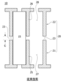
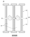
図1および図2は、従来のバッテリーモジュールの構造を説明するための図である。 Figures 1 and 2 are diagrams to explain the structure of a conventional battery module.
図1を参照すると、従来のバッテリーモジュール10は、下部フレーム21、上部フレーム22、および複数のバッテリーセル15を含む。
Referring to FIG. 1, a
下部フレーム21と上部フレーム22は、上下に組み立てられて一つのセルフレーム20を形成する。
The
下部フレーム21には、一つのバッテリーセル15が挿入可能に、下部フレーム21の内部空間27を区画する下部隔壁25が設けられる。上部フレーム22は、下部フレーム21と同じ構造であり、下部隔壁25と対向して設けられた上部隔壁26が設けられる。
The
それぞれのバッテリーセル15は、下部フレーム21の内部空間27に挿入される。次に、上部フレーム22がそれぞれのバッテリーセル15を覆うように下部フレーム21の上部に結合される。
Each
従来の射出工程では、バッテリーセル15の高さに対応する高さでセルフレーム20を製作することが困難である。これにより、セルフレーム20は、下部フレーム21と上部フレーム22とに2つに分離製作され、上下に組み立てられる。
In conventional injection processes, it is difficult to manufacture the
セルフレーム20が一つの構成物で製作されない限り、セルフレーム20は、下部フレーム21と上部フレーム22との継ぎ目部に隙間23が生じる。この隙間23は、互いに対向して配置された下部隔壁25と上部隔壁26との間にも存在する。
Unless the
隙間23は、非常に狭い間隔Gを有する。非常に狭い間隔Gであっても隙間23が存在すれば、セルフレームの内部空間が隙間23を介して流体移動可能に連結される。
The
バッテリーモジュール10に設けられた複数のバッテリーセルのうちいずれか一つのバッテリーセル15が発火した場合、火炎は、隙間23を介して、発火したバッテリーセル15から周辺バッテリーセルに急速に転移し得る。
If any one of the
一般に、バッテリーセル15は、充電時に熱が発生する。バッテリーセル15の充電または使用時に発生する熱を効率的に除去できないと、バッテリーセル15の熱蓄積によりバッテリーセル15が発火し得る。
Generally, the
本発明は、従来、上部フレームと下部フレームとの組立体でセルフレームを構成せず、バッテリーセルの長手方向に上下対称構造を有する一体型のセルフレームを有するバッテリーモジュールを提供することを目的とする。 The present invention aims to provide a battery module that has an integrated cell frame that has a top-bottom symmetrical structure in the longitudinal direction of the battery cell, rather than the conventional cell frame being constructed from an assembly of an upper frame and a lower frame.
また、本発明は、セルフレームがワンピース(one-piece)で製作され、バッテリーセルの外周面を囲むように設けられた防火壁部がセルフレーム内部の全領域に充填されることにより、隣接するバッテリーセル間の火炎の転移を防止できるバッテリーモジュールを提供することを目的とする。 The present invention also aims to provide a battery module that can prevent the transfer of flames between adjacent battery cells by having a cell frame manufactured as a one-piece unit and a fire wall section that is provided to surround the outer periphery of the battery cell and fills the entire area inside the cell frame.
上述した課題を解決するために、本発明の一実施形態に係るバッテリーモジュールは、複数のバッテリーセルと、それぞれのバッテリーセルが挿入されるセル挿入空間およびセル挿入空間を区画し、それぞれのバッテリーセルを支持する支持リブが設けられたセルフレームと、前記セル挿入空間に設けられ、前記それぞれのバッテリーセルを囲むように設けられた防火壁部と、を含む。 In order to solve the above-mentioned problems, a battery module according to one embodiment of the present invention includes a plurality of battery cells, a cell insertion space into which each battery cell is inserted, a cell frame that partitions the cell insertion space and is provided with support ribs that support each battery cell, and a fire wall portion that is provided in the cell insertion space and surrounds each battery cell.
また、前記セルフレームは、前記バッテリーセルの挿入方向に沿って、前記セルフレームの中央部に行くほど少なくとも一部で厚さが厚くなるように設けられる。 In addition, the cell frame is configured so that at least a portion of the cell frame is thicker toward the center of the cell frame along the insertion direction of the battery cell.
また、前記セルフレームは、前記バッテリーセルの挿入方向に沿って、前記セルフレームの上端から前記セルフレームの中央部に行くほど厚さが厚くなるように設けられ、前記中央部から前記セルフレームの下端に行くほど厚さが狭くなるように設けられ得る。 In addition, the cell frame may be configured to be thicker from the upper end of the cell frame to the center of the cell frame along the insertion direction of the battery cell, and to be narrower from the center to the lower end of the cell frame.
また、前記セルフレームは、前記支持リブによって前記セル挿入空間が上下に区画され、前記支持リブの上部である前記セル挿入空間の上部空間と前記支持リブの下部である前記セル挿入空間の下部空間とが互いに流体移動可能に連結され得る。 In addition, the cell frame has a cell insertion space that is divided into upper and lower spaces by the support ribs, and the upper space of the cell insertion space, which is the upper part of the support rib, and the lower space of the cell insertion space, which is the lower part of the support rib, can be connected to each other so that fluid can move between them.
また、前記セルフレームは、上部空間と下部空間とが前記支持リブを基準に互いに対称な形状を有することができる。 In addition, the upper and lower spaces of the cell frame may have shapes that are symmetrical with respect to the support rib.
また、前記防火壁部は、前記セル挿入空間に注入および硬化されることにより、それぞれのバッテリーセルを囲んだ状態であるポッティングレジンを含むことができる。 Additionally, the firewall portion may include a potting resin that is injected into the cell insertion space and hardened to surround each battery cell.
また、前記ポッティングレジンは、前記セル挿入空間の全領域に注入され得る。 The potting resin can also be injected into the entire area of the cell insertion space.
また、前記ポッティングレジンは、シリコン系レジン、ウレタン系レジン、またはエポキシ系レジンのうちいずれか一つを含むことができる。 In addition, the potting resin may include any one of a silicone-based resin, a urethane-based resin, and an epoxy-based resin.
また、前記防火壁部は、前記セル挿入空間の内面と前記それぞれのバッテリーセルの外周面とにそれぞれ接触し、隣接するバッテリーセルを区画するように配置され得る。 In addition, the fire wall portion may be arranged to be in contact with the inner surface of the cell insertion space and the outer peripheral surface of each battery cell, and to separate adjacent battery cells.
また、前記防火壁部は、前記セルフレームの内面と前記セルフレームに最も隣接するバッテリーセルとの間の幅が、バッテリーセルの挿入方向に沿って前記防火壁部の上端から中央部に行くほど狭くなるように設けられ、前記防火壁部の中央部から前記防火壁部の下端に行くほど広くなるように設けられ得る。 The fire wall portion may be configured such that the width between the inner surface of the cell frame and the battery cell closest to the cell frame narrows from the upper end of the fire wall portion to the center along the battery cell insertion direction, and widens from the center of the fire wall portion to the lower end of the fire wall portion.
また、前記支持リブは、前記それぞれのバッテリーセルが挿入される複数のリブホールを有することができる。 Additionally, the support rib may have a plurality of rib holes into which each of the battery cells is inserted.
また、前記支持リブは、前記セルフレームに一体に形成され得る。 The support ribs may also be integrally formed with the cell frame.
また、前記支持リブは、前記リブホールの周りに沿って離隔して配置され、リブホールに挿入されたバッテリーセルの側面を支持するように設けられた複数の支持突起を含むことができる。 The support rib may also include a plurality of support protrusions spaced apart around the rib hole and configured to support the sides of the battery cell inserted into the rib hole.
また、前記支持突起は、前記支持リブの上部または下部のうち少なくとも一方に突出形成され得る。 In addition, the support protrusion may be formed to protrude from at least one of the upper and lower parts of the support rib.
前記バッテリーモジュールは、前記支持リブを上下に貫通し、前記バッテリーセルと並んで配置され、前記支持リブに結合された支持柱をさらに含むことができる。 The battery module may further include a support pillar that passes through the support rib from top to bottom, is arranged alongside the battery cell, and is coupled to the support rib.
また、バッテリーモジュールは、前記支持柱の上部に装着され、前記セルフレームの開放された上部を覆うように前記セルフレームに結合される上部カバーと、前記支持柱の下部に装着され、前記セルフレームの開放された下部を覆うように前記セルフレームに結合される下部カバーと、をさらに含むことができる。 The battery module may further include an upper cover attached to the upper part of the support pillar and coupled to the cell frame to cover the open upper part of the cell frame, and a lower cover attached to the lower part of the support pillar and coupled to the cell frame to cover the open lower part of the cell frame.
以上で述べた通り、本発明の一実施形態に係るバッテリーモジュールは、次のような効果を有する。 As described above, the battery module according to one embodiment of the present invention has the following effects:
従来のセルフレームが上部フレームと下部フレームとの組立体から構成されるのとは異なり、本発明において、セルフレームは、バッテリーセルの挿入方向(または「セルフレームの高さ方向」)に一体型で製作される。 Unlike conventional cell frames that are constructed from an assembly of an upper frame and a lower frame, in the present invention, the cell frame is manufactured as a single unit in the direction in which the battery cells are inserted (or in the "height direction of the cell frame").
また、セルフレームの中央部を基準に上下対称構造を有するワンピース(one-piece)で製作され、それぞれのバッテリーセルを囲むようにセルフレームの内側空間に充填された防火壁部がバッテリーセル間の火災の転移を防止することができる。 In addition, the battery is manufactured as a one-piece unit with a vertically symmetrical structure based on the center of the cell frame, and the fire walls that surround each battery cell and fill the inner space of the cell frame prevent the spread of fire between battery cells.
また、一体に形成されたセルフレームの構造的特徴として、セルフレームの厚さがセルフレームの中央から上端および下端に向かって行くほど小さくなるように設けられることにより、防火壁部の厚さをより厚く形成することができ、その結果、バッテリーセル間の火災の転移を効果的に防止することができる。 In addition, a structural feature of the integrally formed cell frame is that the thickness of the cell frame becomes thinner from the center toward the upper and lower ends of the cell frame, which allows the thickness of the fire wall to be made thicker, thereby effectively preventing the spread of fire between battery cells.
従来のバッテリーモジュールは、セルフレームを構成する上部フレームと下部フレームとが上下に結合される構造を有し、組み立て後、上部フレームと下部フレームとの間に隙間が生じるのに対して、本発明は、一体型のセルフレームに複数のバッテリーセルを挿入後、セルフレームのセル挿入空間に難燃素材を注入および硬化させることにより、防火壁部を一体に形成することができる。 Conventional battery modules have a structure in which an upper frame and a lower frame that make up the cell frame are joined vertically, and after assembly, a gap is created between the upper frame and the lower frame. In contrast, the present invention inserts multiple battery cells into an integrated cell frame, and then injects and hardens a flame-retardant material into the cell insertion space of the cell frame to form an integrated fire wall section.
以下、本発明の一実施形態に係るバッテリーモジュールについて添付図面を参照して詳細に説明する。 Below, a battery module according to one embodiment of the present invention will be described in detail with reference to the attached drawings.
また、図面符号にかかわらず同一または対応する構成要素については同一または類似の参照番号を付し、これに対する重複説明は省略するようにし、説明の便宜のために示された各構成部材の大きさおよび形状は誇張または縮小されることがある。 In addition, regardless of the drawing symbols, identical or similar reference numbers will be used for identical or corresponding components, and duplicate explanations will be omitted. For ease of explanation, the size and shape of each component shown may be exaggerated or reduced.
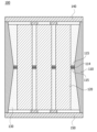
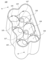
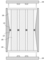
図3は、本発明の一実施形態に係るバッテリーモジュール100の断面図を概略的に示す図であり、図4は、本発明の一実施形態に係るセルフレームの斜視図を概略的に示す図であり、図5は、本発明の一実施形態に係るセルフレームの断面図を概略的に示す図である。
Figure 3 is a schematic cross-sectional view of a
図3を参照すると、本発明の一実施形態に係るバッテリーモジュール100は、セルフレーム110、複数のバッテリーセル120、および防火壁部130を含む。
Referring to FIG. 3, a
また、それぞれのバッテリーセル120は、円筒形状のバッテリーであり得る。
Additionally, each
具体的には、本発明の一実施形態に係るバッテリーモジュール100は、複数のバッテリーセル120と、それぞれのバッテリーセル120が挿入されるセル挿入空間111およびセル挿入空間111を区画し、それぞれのバッテリーセル120を支持する支持リブ114が設けられたセルフレーム110と、セル挿入空間111に設けられ、それぞれのバッテリーセル120を囲むように設けられた防火壁部130と、を含む。
Specifically, the
図4および図5を参照すると、セルフレーム110は、複数のバッテリーセル120を収容するためのケースである。セルフレーム110には、セル挿入空間111および支持リブ114が設けられる。セル挿入空間111は、複数のバッテリーセル120が挿入される空間である。
Referring to Figures 4 and 5, the
セルフレーム110は、上部と下部がそれぞれ開放され得る。
The
セルフレーム110は、支持リブ114によってセル挿入空間111が上下に区画される。このとき、支持リブ114の上部であるセル挿入空間111の上部空間111aと支持リブ114の下部であるセル挿入空間111の下部空間111bとは、互いに流体移動可能に連結され得る。また、上部空間111aおよび下部空間111bは、支持リブ114を基準に上下対称に設けられ得る。
In the
例えば、セルフレーム110は、上部空間111aと下部空間111bとが支持リブ114を基準に互いに対称な形状を有することができる。また、支持リブ114は、セルフレーム110に一体に形成され得る。
For example, the
図3において、x軸方向は、セルフレーム110内に配置された複数のバッテリーセル120の配列方向またはバッテリーセル120の半径方向を示す。そして、y軸方向は、バッテリーセル120の挿入方向またはセルフレーム110の高さ方向を示す。
3, the x-axis direction indicates the arrangement direction of the
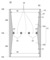
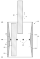
図6は、本発明の一実施形態に係るセルフレームのセル挿入空間にバッテリーセルが挿入される過程を説明するための図であり、図7は、本発明の一実施形態において、バッテリーセルがセルフレームに挿入された状態を説明するための図である。 Figure 6 is a diagram illustrating the process of inserting a battery cell into a cell insertion space of a cell frame according to one embodiment of the present invention, and Figure 7 is a diagram illustrating the state in which a battery cell is inserted into a cell frame in one embodiment of the present invention.
セルフレーム110は、高さ方向に沿って一体に形成され得る。セルフレーム110は、ワンピースで製造されることにより、バッテリーセル120の挿入方向F1(図6参照)に沿って、セルフレーム110の上端110bからセルフレーム110の中央部110aに行くほど厚さt1が厚くなるように設けられ、中央部110aからセルフレームの下端110cに行くほど厚さt2が狭くなるように設けられ得る。
The
図5および図6を参照すると、セルフレーム110は、バッテリーセルの挿入方向F1に沿って、セルフレーム110の上端110bからセルフレーム110の中央部110aに行くほどセルフレーム110のセル挿入空間111の幅W1が狭くなるように設けられる。
Referring to Figures 5 and 6, the
すなわち、セルフレーム110は、セルフレーム110の上端110bからセルフレーム110の中央部110aに行くほど、セル挿入空間111の上部空間111aの幅W1が狭くなるように設けられる。
In other words, the
また、セルフレーム110の上端部110dは、バッテリーセルの挿入方向F1に沿って、セルフレーム110の上端110bからセルフレーム110の中央部110aに行くほど厚さt1が厚くなるように設けられる。厚さt1は、セルフレーム110の上端部110dにおいて、セルフレーム110の外面112と内面113との間の間隔である。
The
また、セルフレーム110の上端部110dは、バッテリーセルの挿入方向F1に沿って、セルフレーム110の上端110bからセルフレーム110の中央部110aに行くほど少なくとも一部で厚さt1が厚くなるように設けられ得る。
In addition, the
また、セルフレーム110の上端部110dは、バッテリーセルの挿入方向F1に沿って、セルフレーム110の上端110bからセルフレーム110の中央部110aに行くほど厚さt1が継続的に厚くなるように設けられ得る。
In addition, the
また、セルフレーム110の上端部110dは、バッテリーセルの挿入方向F1に沿って、セルフレーム110の上端110bからセルフレーム110の中央部110aに行くほど厚さt1が線形に厚くなるように設けられ得る。
In addition, the
ここで、セルフレームの上端部110dは、上部空間111aが設けられた部分を指称する。また、上部空間111aは、ほぼ逆台形状の断面を有することができる。
Here, the
また、セルフレーム110は、上部空間111aと下部空間111bとが支持リブ114を基準に互いに対称な形状を有することができる。
In addition, the
セルフレーム110は、バッテリーセルの挿入方向F1に沿って、セルフレーム110の中央部110aからセルフレーム110の下端110cに行くほどセル挿入空間111の幅W2が広くなるように設けられる。
The
すなわち、セルフレーム110は、バッテリーセルの挿入方向F1に沿って、セルフレーム110の中央部110aからセルフレーム110の下端110cに行くほどセル挿入空間111の下部空間111bの幅W2が広くなるように設けられる。
That is, the
セルフレームの下端部110eは、バッテリーセルの挿入方向F1に沿って、中央部110aからセルフレームの下端110cに行くほど厚さt2が小さくなるように設けられる。厚さt2は、セルフレーム110の下端部110eにおいて、セルフレーム110の外面112と内面113との間の間隔である。
The
また、セルフレームの下端部110eは、バッテリーセルの挿入方向F1に沿って、中央部110aからセルフレームの下端110cに行くほど少なくとも一部で厚さt2が小さくなるように設けられる。
The
また、セルフレームの下端部110eは、バッテリーセルの挿入方向F1に沿って、中央部110aからセルフレームの下端110cに行くほど厚さt2が継続的に小さくなるように設けられ得る。
In addition, the
また、セルフレームの下端部110eは、バッテリーセルの挿入方向F1に沿って、中央部110aからセルフレームの下端110cに行くほど厚さt2が線形的に小さくなるように設けられ得る。
In addition, the
ここで、セルフレーム110の下端部110eは、下部空間111bが設けられた部分を指称する。また、下部空間111bは、台形状の断面を有することができる。
Here, the
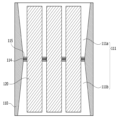
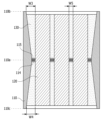
図8は、本発明の一実施形態において、セルフレームのセル挿入空間に設けられた防火壁部の構造を説明するための図であり、図9は、本発明の一実施形態において、上部カバーと下部カバーとがセルフレームに結合される過程を説明するための図である。 Figure 8 is a diagram to explain the structure of a fire wall section provided in the cell insertion space of a cell frame in one embodiment of the present invention, and Figure 9 is a diagram to explain the process in which an upper cover and a lower cover are joined to a cell frame in one embodiment of the present invention.
防火壁部130は、セル挿入空間111に注入および硬化されることにより、それぞれのバッテリーセルを囲んだ状態であるポッティングレジンを含むことができる。
The
また、防火壁部130は、難燃性を有する難燃素材で形成され得る。防火壁部130は、セル挿入空間111の内面とそれぞれのバッテリーセル120の外周面とを囲むように設けられる。
In addition, the
また、防火壁部130は、セル挿入空間111の内面とそれぞれのバッテリーセル120の外周面とにそれぞれ接触し、隣接するバッテリーセル120を区画するように配置される。すなわち、隣接するバッテリーセル120間の空間に防火壁部130が充填形成される。また、防火壁部130は、セルフレーム110の内面と、セルフレーム110に最も隣接するバッテリーセル120との間の空間にも充填形成される。
The
また、防火壁部130は、難燃素材がセル挿入空間111内にバッテリーセル120間の空間に注入および硬化されて形成され得る。また、ポッティングレジンは、セル挿入空間111の全領域に注入され得る。
In addition, the
本明細書では、難燃素材は、シリコンと難燃剤とを混合したポッティングレジン(potting resin)が使用され得る。本実施形態では、ポッティングレジンは、シリコン系レジン、ウレタン系レジン、またはエポキシ系レジンのうちいずれか一つを含むことができる。 In this specification, the flame retardant material may be a potting resin made by mixing silicone and a flame retardant. In this embodiment, the potting resin may include any one of a silicone-based resin, a urethane-based resin, and an epoxy-based resin.
防火壁部130は、セル挿入空間111の内面とそれぞれのバッテリーセル120の外周面とに接触し、隣接するバッテリーセル120を区画する。
The
図8を参照すると、上部空間111aにおいて、防火壁部130は、セルフレーム110の内面とセルフレーム110に隣接するバッテリーセル120との間の幅W3がセルフレーム110の上端110bから中央部110aに行くほど狭くなるように設けられる。
Referring to FIG. 8, in the
すなわち、防火壁部130は、セルフレーム110の内面(セル挿入空間を形成する面)と、セルフレーム110に最も隣接するバッテリーセル120との間の幅W3が、セルフレーム110の上端110bから中央部110aに行くほど狭くなるように設けられ得る。
That is, the
また、防火壁部130は、セルフレーム110の内面113(セル挿入空間を形成する面)と、セルフレーム110に最も隣接するバッテリーセル120との間の幅W4が、バッテリーセルの挿入方向に沿って、セルフレーム110の中央部110aからセルフレーム110の下端110cに行くほど増加するように設けられ得る。
The
また、防火壁部130は、隣接する2つのバッテリーセル間の空間にも配置され、このとき、互いに隣接する2つのバッテリーセル120を区画する防火壁部130は、バッテリーセルの挿入方向に沿って厚さW5がほぼ一定に設けられ得る。
In addition, the
図4および図5を参照すると、支持リブ114は、それぞれのバッテリーセル120が挿入される複数のリブホール116を有することができる。また、それぞれのリブホール116には、それぞれのバッテリーセル120が挿入される。
Referring to FIG. 4 and FIG. 5, the
支持リブ114は、セル挿入空間111が上下に区画されるようにセルフレーム110に一体に形成される。また、支持リブ114は、セル挿入空間111に挿入されたそれぞれのバッテリーセル120を一体に支持する。
The
また、支持リブ114は、リブホール116の周りに沿って離隔して配置され、リブホール116に挿入されたバッテリーセル120の側面を支持するように設けられた複数の支持突起115を含むことができる。一例として、支持突起115は、支持リブ114の上部または下部のうち少なくとも一方に突出形成され得る。また、支持突起115は、支持リブ114と一体に形成され得る。
In addition, the
また、支持リブ114は、所定の幅間隔W5でバッテリーセル120の外周面を囲むように設けられ得、互いに隣接する2つのバッテリーセル120を幅間隔W5だけ離隔させることができる。例えば、隣接するリブホール116は、所定の幅間隔W5を有するように離れて配置され得る。また、隣接する2つのバッテリーセル間の空間には、防火壁部130が充填される。
In addition, the
図4および図5を参照すると、支持リブ114は、セル挿入空間111が上下に区画されるようにセルフレーム110に設けられる。支持リブ114は、それぞれのバッテリーセル120を側面支持し、それぞれのバッテリーセル120が一定の間隔で離隔して配置されるように設けられる。
Referring to FIG. 4 and FIG. 5, the
それぞれのバッテリーセル120は、それぞれのリブホール116を貫通してセル挿入空間111に挿入される。支持突起115は、バッテリーセル120の外周面と接してバッテリーセル120の側面を支持することができる。
Each
バッテリーモジュール100は、支持リブ114を上下に貫通し、バッテリーセル120と並んで配置され、支持リブ114に結合された支持柱117を含むことができる。
The
支持柱117は、支持リブ114を上下に貫通して支持リブ114に結合され、バッテリーセル120と並んで配置され、支持リブ114を支持する。
The
バッテリーモジュール100は、支持柱117の上部に装着され、セルフレーム110の開放された上部を覆うようにセルフレーム110に結合される上部カバー140と、支持柱117の下部に装着され、セルフレーム110の開放された下部を覆うようにセルフレーム110に結合される下部カバー150とを含むことができる。
The
一例として、支持柱117には、上部カバー140と下部カバー150とが嵌合され得る。
As an example, an
図9を参照すると、上部カバー140は、支持柱117の上部に嵌合されて、セルフレーム110の開放された上部を覆うようにセルフレーム110に結合され得る。また、下部カバー150は、支持柱117の下部に嵌合されて、セルフレーム110の開放された下部を覆うようにセルフレーム110に結合され得る。
Referring to FIG. 9, the
以下、上記のように構成されるバッテリーモジュールの製造方法について説明する。 The manufacturing method for the battery module configured as above is described below.
図4および図5を参照すると、セル挿入空間111と支持リブ114とが設けられたセルフレーム110が準備される。
Referring to Figures 4 and 5, a
図6を参照すると、それぞれのバッテリーセル120がそれぞれのリブホール116を貫通してセル挿入空間111に挿入される。
Referring to FIG. 6, each
図7を参照すると、複数のバッテリーセル120がセル挿入空間111に挿入されると、難燃素材がセル挿入空間111に注入される。上述したように、難燃素材は、シリコンと難燃剤とを混合したポッティングレジン(potting resin)が使用され得る。また、ポッティングレジンは、シリコン系レジン、ウレタン系レジン、またはエポキシ系レジンのうちいずれか一つである。
Referring to FIG. 7, when a plurality of
図8を参照すると、充填された難燃素材が硬化されながら、セル挿入空間111の内面とそれぞれのバッテリーセル120の外周面とを囲む防火壁部130が形成される。
Referring to FIG. 8, as the filled flame-retardant material hardens, a
防火壁部130は、セル挿入空間111の内面とそれぞれのバッテリーセル120の外周面とにそれぞれ接触し、セル挿入空間111でそれぞれのバッテリーセル120を囲むようになり、防火壁部130は、互いに隣接するバッテリーセル120が互いに区画する防火壁を形成する。
The
図9を参照すると、上部カバー140が支持柱117の上部に嵌合されて、セルフレーム110の開放された上部を覆い、下部カバー150が支持柱117の下部に嵌合されて、セルフレーム110の開放された下部を覆う。
Referring to FIG. 9, the
また、セルフレーム110がワンピース(one-piece)で製作されることにより、セルフレーム110の継ぎ目部がなく、継ぎ目部による間隔G(図1参照)もない。
In addition, because the
また、防火壁部130が、セル挿入空間111の全領域に充填および硬化され、それぞれのバッテリーセル120を囲むように設けられるため、発火したバッテリーセルの火炎の周辺のバッテリーセルへの転移を遮断して、バッテリーセルの連鎖発火を防止することができる。
In addition, the
上述した本発明の望ましい実施形態は、例示の目的のために開示されたものであり、本発明に対する通常の知識を有する当業者であれば、本発明の思想と範囲内で多様な修正、変更、付加が可能であり、このような修正、変更、および付加は、下記の請求範囲に属するものと見なすべきである。 The preferred embodiments of the present invention described above have been disclosed for illustrative purposes, and various modifications, changes, and additions may be made by those skilled in the art with ordinary skill in the art within the spirit and scope of the present invention, and such modifications, changes, and additions are to be considered as falling within the scope of the following claims.
Claims (15)
それぞれのバッテリーセルが挿入されるセル挿入空間と、前記セル挿入空間を区画し、前記それぞれのバッテリーセルを支持する支持リブとが設けられたセルフレームと、
前記セル挿入空間に設けられ、前記それぞれのバッテリーセルを囲むように設けられた防火壁部と、を含み、
前記セルフレームは、前記バッテリーセルの挿入方向に沿って、前記セルフレームの中央部に行くほど少なくとも一部で厚さが厚くなるように設けられる、
バッテリーモジュール。 A plurality of battery cells;
a cell frame including a cell insertion space into which each battery cell is inserted and a support rib that partitions the cell insertion space and supports each battery cell;
a fire wall portion provided in the cell insertion space so as to surround each of the battery cells;
The cell frame is provided such that a thickness at least partially increases toward a center portion of the cell frame along an insertion direction of the battery cell.
Battery module.
請求項1に記載のバッテリーモジュール。 The cell frame is configured to have a thickness that increases from an upper end of the cell frame to a central portion of the cell frame along an insertion direction of the battery cell, and a thickness that decreases from the central portion to a lower end of the cell frame.
The battery module according to claim 1 .
請求項1に記載のバッテリーモジュール。 In the cell frame, the cell insertion space is divided into upper and lower spaces by the support rib, and an upper space of the cell insertion space, which is an upper part of the support rib, and a lower space of the cell insertion space, which is a lower part of the support rib, are connected to each other so as to be capable of moving fluid therebetween.
The battery module according to claim 1 .
請求項1に記載のバッテリーモジュール。 The cell frame has an upper space and a lower space each having a shape symmetrical to each other with respect to the support rib.
The battery module according to claim 1 .
請求項1に記載のバッテリーモジュール。 The firewall portion includes a potting resin that is injected into the cell insertion space and hardened to surround each of the battery cells.
The battery module according to claim 1 .
請求項5に記載のバッテリーモジュール。 The potting resin is injected into the entire area of the cell insertion space.
The battery module according to claim 5 .
請求項6に記載のバッテリーモジュール。 The potting resin is any one of a silicone resin, a urethane resin, and an epoxy resin.
The battery module according to claim 6.
請求項1に記載のバッテリーモジュール。 the fire wall portions are disposed in contact with an inner surface of the cell insertion space and an outer peripheral surface of each of the battery cells, respectively, to partition adjacent battery cells;
The battery module according to claim 1 .
請求項8に記載のバッテリーモジュール。 the firewall portion is provided such that a width between an inner surface of the cell frame and a battery cell adjacent to the cell frame becomes narrower from an upper end of the firewall portion to a center portion along an insertion direction of the battery cells, and becomes wider from the center portion of the firewall portion to a lower end of the firewall portion,
The battery module according to claim 8.
請求項1に記載のバッテリーモジュール。 The support rib has a plurality of rib holes into which the respective battery cells are inserted.
The battery module according to claim 1 .
請求項10に記載のバッテリーモジュール。 The support rib is integrally formed with the cell frame.
The battery module according to claim 10.
請求項10に記載のバッテリーモジュール。 the support rib includes a plurality of support protrusions spaced apart from one another along a periphery of the rib hole and configured to support a side surface of the battery cell inserted into the rib hole;
The battery module according to claim 10.
請求項12に記載のバッテリーモジュール。 The support protrusion is formed to protrude from at least one of the upper and lower parts of the support rib.
The battery module according to claim 12.
請求項1に記載のバッテリーモジュール。 The battery cell further includes a support pillar that penetrates the support rib from top to bottom, is arranged next to the battery cell, and is coupled to the support rib.
The battery module according to claim 1 .
前記支持柱の下部に装着され、前記セルフレームの開放された下部を覆うように前記セルフレームに結合される下部カバーと、をさらに含む、
請求項14に記載のバッテリーモジュール。
an upper cover attached to the upper part of the support column and coupled to the cell frame to cover an open upper part of the cell frame;
a lower cover attached to a lower portion of the support column and coupled to the cell frame to cover an open lower portion of the cell frame,
The battery module according to claim 14.
Applications Claiming Priority (3)
| Application Number | Priority Date | Filing Date | Title |
|---|---|---|---|
| KR1020220122411A KR20240043384A (en) | 2022-09-27 | 2022-09-27 | Battery module for preventing chain ignition and Battery module manufacturing method therefor |
| KR10-2022-0122411 | 2022-09-27 | ||
| PCT/KR2023/014808 WO2024071985A1 (en) | 2022-09-27 | 2023-09-26 | Battery module |
Publications (2)
| Publication Number | Publication Date |
|---|---|
| JP2024541663A true JP2024541663A (en) | 2024-11-08 |
| JP7801002B2 JP7801002B2 (en) | 2026-01-16 |
Family
ID=90478630
Family Applications (1)
| Application Number | Title | Priority Date | Filing Date |
|---|---|---|---|
| JP2024532988A Active JP7801002B2 (en) | 2022-09-27 | 2023-09-26 | Battery Module |
Country Status (7)
| Country | Link |
|---|---|
| US (1) | US20250038330A1 (en) |
| EP (1) | EP4432442B1 (en) |
| JP (1) | JP7801002B2 (en) |
| KR (1) | KR20240043384A (en) |
| CN (1) | CN118661323A (en) |
| ES (1) | ES3061567T3 (en) |
| WO (1) | WO2024071985A1 (en) |
Citations (3)
| Publication number | Priority date | Publication date | Assignee | Title |
|---|---|---|---|---|
| JP2010097836A (en) * | 2008-10-17 | 2010-04-30 | Panasonic Corp | Battery pack, electronic equipment using it as power source, and battery pack case |
| JP3211262U (en) * | 2017-01-04 | 2017-06-29 | 益陽科力遠電池有限責任公司YiYang Corun Battery Co., Ltd. | Fireproof battery pack |
| JP2023514713A (en) * | 2020-09-04 | 2023-04-07 | エルジー エナジー ソリューション リミテッド | Battery modules, battery packs, and automobiles |
Family Cites Families (7)
| Publication number | Priority date | Publication date | Assignee | Title |
|---|---|---|---|---|
| JP2009211907A (en) | 2008-03-04 | 2009-09-17 | Panasonic Corp | Battery module and battery pack using the same |
| FR2962261B1 (en) * | 2010-07-02 | 2013-08-02 | Saft Groupe Sa | BATTERY OF ELECTROCHEMICAL GENERATORS COMPRISING FOAM AS FILLING MATERIAL BETWEEN GENERATORS |
| US9892868B2 (en) * | 2013-06-21 | 2018-02-13 | Ioxus, Inc. | Energy storage device assembly |
| KR102876434B1 (en) * | 2020-11-05 | 2025-10-23 | 주식회사 엘지에너지솔루션 | Secondary battery module and secondary battery pack including the same and vehicle including the same |
| JP7640585B2 (en) * | 2021-02-22 | 2025-03-05 | エルジー エナジー ソリューション リミテッド | Battery pack and automobile including same |
| KR102911027B1 (en) | 2021-02-26 | 2026-01-09 | 현대모비스 주식회사 | Method for wireless update of on board unit using portable terminal |
| CN114944533A (en) * | 2022-06-08 | 2022-08-26 | 浙江丰锂科技发展有限公司 | Exempt from to weld electric core installing support and package assembly |
-
2022
- 2022-09-27 KR KR1020220122411A patent/KR20240043384A/en active Pending
-
2023
- 2023-09-26 ES ES23873099T patent/ES3061567T3/en active Active
- 2023-09-26 CN CN202380015773.4A patent/CN118661323A/en active Pending
- 2023-09-26 EP EP23873099.8A patent/EP4432442B1/en active Active
- 2023-09-26 US US18/716,646 patent/US20250038330A1/en active Pending
- 2023-09-26 WO PCT/KR2023/014808 patent/WO2024071985A1/en not_active Ceased
- 2023-09-26 JP JP2024532988A patent/JP7801002B2/en active Active
Patent Citations (3)
| Publication number | Priority date | Publication date | Assignee | Title |
|---|---|---|---|---|
| JP2010097836A (en) * | 2008-10-17 | 2010-04-30 | Panasonic Corp | Battery pack, electronic equipment using it as power source, and battery pack case |
| JP3211262U (en) * | 2017-01-04 | 2017-06-29 | 益陽科力遠電池有限責任公司YiYang Corun Battery Co., Ltd. | Fireproof battery pack |
| JP2023514713A (en) * | 2020-09-04 | 2023-04-07 | エルジー エナジー ソリューション リミテッド | Battery modules, battery packs, and automobiles |
Also Published As
| Publication number | Publication date |
|---|---|
| EP4432442A1 (en) | 2024-09-18 |
| CN118661323A (en) | 2024-09-17 |
| EP4432442A4 (en) | 2025-07-16 |
| EP4432442B1 (en) | 2026-01-21 |
| JP7801002B2 (en) | 2026-01-16 |
| KR20240043384A (en) | 2024-04-03 |
| US20250038330A1 (en) | 2025-01-30 |
| WO2024071985A1 (en) | 2024-04-04 |
| ES3061567T3 (en) | 2026-04-06 |
Similar Documents
| Publication | Publication Date | Title |
|---|---|---|
| US10347894B2 (en) | Energy storage system | |
| JP3676675B2 (en) | Explosion-proof penetration connector | |
| KR101050315B1 (en) | Secondary battery module | |
| KR20260041699A (en) | Energy Storage System | |
| US10319969B2 (en) | Lead-acid battery and method of manufacturing lid member of lead-acid battery | |
| JP6380219B2 (en) | Manufacturing method of assembled battery and assembled battery | |
| KR20210137271A (en) | Carrying box for battery cell | |
| KR20220153897A (en) | Battery pack | |
| KR102900649B1 (en) | Battery moule and battery pack including the same | |
| KR20210129512A (en) | A battery module having a flame discharge prevention structure, and a battery pack and Energy storagy system including the battery module | |
| JP2024541663A (en) | Battery Module | |
| CN118249031A (en) | Unit carrier support, unit carrier composite system, battery carrier and battery housing | |
| KR20200131022A (en) | Battery module assemble and manufacturing method thereof | |
| JP7121062B2 (en) | lead acid battery | |
| KR102688894B1 (en) | Insulation frame and insulation system having the same | |
| KR20230037361A (en) | Module for construction, module assebly for construction including the same and methof for manufacturing module assebly for construction | |
| US20220263199A1 (en) | Battery module | |
| KR102771205B1 (en) | Assembly block structure of drywall and manufacturing method thereof | |
| US12506216B2 (en) | Battery accommodation tray | |
| JP2025524293A (en) | Battery module and battery pack including same | |
| EP4550532A1 (en) | Battery module and battery pack including same | |
| KR100734053B1 (en) | Terminal assembly structure of junction box and its method | |
| KR102873885B1 (en) | Sealing device for a perovskite solar cell module and a sealing method using it | |
| KR102767044B1 (en) | Junction structure for modular building joined without fastening | |
| KR102302926B1 (en) | Manufacturing method of heat sink unit having arbitrary shape |
Legal Events
| Date | Code | Title | Description |
|---|---|---|---|
| A621 | Written request for application examination |
Free format text: JAPANESE INTERMEDIATE CODE: A621 Effective date: 20240603 |
|
| A977 | Report on retrieval |
Free format text: JAPANESE INTERMEDIATE CODE: A971007 Effective date: 20250714 |
|
| A131 | Notification of reasons for refusal |
Free format text: JAPANESE INTERMEDIATE CODE: A131 Effective date: 20250722 |
|
| TRDD | Decision of grant or rejection written | ||
| A01 | Written decision to grant a patent or to grant a registration (utility model) |
Free format text: JAPANESE INTERMEDIATE CODE: A01 Effective date: 20251202 |
|
| A61 | First payment of annual fees (during grant procedure) |
Free format text: JAPANESE INTERMEDIATE CODE: A61 Effective date: 20251224 |
|
| R150 | Certificate of patent or registration of utility model |
Ref document number: 7801002 Country of ref document: JP Free format text: JAPANESE INTERMEDIATE CODE: R150 |