JP2024528126A - Surgical Instruments - Google Patents
Surgical Instruments Download PDFInfo
- Publication number
- JP2024528126A JP2024528126A JP2024505542A JP2024505542A JP2024528126A JP 2024528126 A JP2024528126 A JP 2024528126A JP 2024505542 A JP2024505542 A JP 2024505542A JP 2024505542 A JP2024505542 A JP 2024505542A JP 2024528126 A JP2024528126 A JP 2024528126A
- Authority
- JP
- Japan
- Prior art keywords
- load unit
- response
- electrical
- load
- sliding member
- Prior art date
- Legal status (The legal status is an assumption and is not a legal conclusion. Google has not performed a legal analysis and makes no representation as to the accuracy of the status listed.)
- Pending
Links
Images


Classifications
-
- A—HUMAN NECESSITIES
- A61—MEDICAL OR VETERINARY SCIENCE; HYGIENE
- A61B—DIAGNOSIS; SURGERY; IDENTIFICATION
- A61B17/00—Surgical instruments, devices or methods
- A61B17/11—Surgical instruments, devices or methods for performing anastomosis; Buttons for anastomosis
- A61B17/115—Staplers for performing anastomosis, e.g. in a single operation
-
- A—HUMAN NECESSITIES
- A61—MEDICAL OR VETERINARY SCIENCE; HYGIENE
- A61B—DIAGNOSIS; SURGERY; IDENTIFICATION
- A61B17/00—Surgical instruments, devices or methods
- A61B17/00234—Surgical instruments, devices or methods for minimally invasive surgery
-
- A—HUMAN NECESSITIES
- A61—MEDICAL OR VETERINARY SCIENCE; HYGIENE
- A61B—DIAGNOSIS; SURGERY; IDENTIFICATION
- A61B17/00—Surgical instruments, devices or methods
- A61B17/068—Surgical staplers, e.g. containing multiple staples or clamps
- A61B17/072—Surgical staplers, e.g. containing multiple staples or clamps for applying a row of staples in a single action, e.g. the staples being applied simultaneously
- A61B17/07207—Surgical staplers, e.g. containing multiple staples or clamps for applying a row of staples in a single action, e.g. the staples being applied simultaneously the staples being applied sequentially
-
- A—HUMAN NECESSITIES
- A61—MEDICAL OR VETERINARY SCIENCE; HYGIENE
- A61B—DIAGNOSIS; SURGERY; IDENTIFICATION
- A61B90/00—Instruments, implements or accessories specially adapted for surgery or diagnosis and not covered by any of the groups A61B1/00 - A61B50/00, e.g. for luxation treatment or for protecting wound edges
- A61B90/08—Accessories or related features not otherwise provided for
-
- A—HUMAN NECESSITIES
- A61—MEDICAL OR VETERINARY SCIENCE; HYGIENE
- A61B—DIAGNOSIS; SURGERY; IDENTIFICATION
- A61B90/00—Instruments, implements or accessories specially adapted for surgery or diagnosis and not covered by any of the groups A61B1/00 - A61B50/00, e.g. for luxation treatment or for protecting wound edges
- A61B90/90—Identification means for patients or instruments, e.g. tags
-
- A—HUMAN NECESSITIES
- A61—MEDICAL OR VETERINARY SCIENCE; HYGIENE
- A61B—DIAGNOSIS; SURGERY; IDENTIFICATION
- A61B17/00—Surgical instruments, devices or methods
- A61B2017/00017—Electrical control of surgical instruments
-
- A—HUMAN NECESSITIES
- A61—MEDICAL OR VETERINARY SCIENCE; HYGIENE
- A61B—DIAGNOSIS; SURGERY; IDENTIFICATION
- A61B17/00—Surgical instruments, devices or methods
- A61B17/00234—Surgical instruments, devices or methods for minimally invasive surgery
- A61B2017/00353—Surgical instruments, devices or methods for minimally invasive surgery one mechanical instrument performing multiple functions, e.g. cutting and grasping
-
- A—HUMAN NECESSITIES
- A61—MEDICAL OR VETERINARY SCIENCE; HYGIENE
- A61B—DIAGNOSIS; SURGERY; IDENTIFICATION
- A61B17/00—Surgical instruments, devices or methods
- A61B2017/00367—Details of actuation of instruments, e.g. relations between pushing buttons, or the like, and activation of the tool, working tip, or the like
- A61B2017/00398—Details of actuation of instruments, e.g. relations between pushing buttons, or the like, and activation of the tool, working tip, or the like using powered actuators, e.g. stepper motors, solenoids
-
- A—HUMAN NECESSITIES
- A61—MEDICAL OR VETERINARY SCIENCE; HYGIENE
- A61B—DIAGNOSIS; SURGERY; IDENTIFICATION
- A61B17/00—Surgical instruments, devices or methods
- A61B2017/0046—Surgical instruments, devices or methods with a releasable handle; with handle and operating part separable
-
- A—HUMAN NECESSITIES
- A61—MEDICAL OR VETERINARY SCIENCE; HYGIENE
- A61B—DIAGNOSIS; SURGERY; IDENTIFICATION
- A61B17/00—Surgical instruments, devices or methods
- A61B2017/0046—Surgical instruments, devices or methods with a releasable handle; with handle and operating part separable
- A61B2017/00473—Distal part, e.g. tip or head
-
- A—HUMAN NECESSITIES
- A61—MEDICAL OR VETERINARY SCIENCE; HYGIENE
- A61B—DIAGNOSIS; SURGERY; IDENTIFICATION
- A61B17/00—Surgical instruments, devices or methods
- A61B2017/00477—Coupling
- A61B2017/00482—Coupling with a code
-
- A—HUMAN NECESSITIES
- A61—MEDICAL OR VETERINARY SCIENCE; HYGIENE
- A61B—DIAGNOSIS; SURGERY; IDENTIFICATION
- A61B17/00—Surgical instruments, devices or methods
- A61B2017/00982—General structural features
-
- A—HUMAN NECESSITIES
- A61—MEDICAL OR VETERINARY SCIENCE; HYGIENE
- A61B—DIAGNOSIS; SURGERY; IDENTIFICATION
- A61B17/00—Surgical instruments, devices or methods
- A61B17/068—Surgical staplers, e.g. containing multiple staples or clamps
- A61B17/072—Surgical staplers, e.g. containing multiple staples or clamps for applying a row of staples in a single action, e.g. the staples being applied simultaneously
- A61B2017/07214—Stapler heads
- A61B2017/07285—Stapler heads characterised by its cutter
-
- A—HUMAN NECESSITIES
- A61—MEDICAL OR VETERINARY SCIENCE; HYGIENE
- A61B—DIAGNOSIS; SURGERY; IDENTIFICATION
- A61B90/00—Instruments, implements or accessories specially adapted for surgery or diagnosis and not covered by any of the groups A61B1/00 - A61B50/00, e.g. for luxation treatment or for protecting wound edges
- A61B90/08—Accessories or related features not otherwise provided for
- A61B2090/0803—Counting the number of times an instrument is used
-
- A—HUMAN NECESSITIES
- A61—MEDICAL OR VETERINARY SCIENCE; HYGIENE
- A61B—DIAGNOSIS; SURGERY; IDENTIFICATION
- A61B90/00—Instruments, implements or accessories specially adapted for surgery or diagnosis and not covered by any of the groups A61B1/00 - A61B50/00, e.g. for luxation treatment or for protecting wound edges
- A61B90/08—Accessories or related features not otherwise provided for
- A61B2090/0807—Indication means
- A61B2090/0808—Indication means for indicating correct assembly of components, e.g. of the surgical apparatus
-
- A—HUMAN NECESSITIES
- A61—MEDICAL OR VETERINARY SCIENCE; HYGIENE
- A61B—DIAGNOSIS; SURGERY; IDENTIFICATION
- A61B90/00—Instruments, implements or accessories specially adapted for surgery or diagnosis and not covered by any of the groups A61B1/00 - A61B50/00, e.g. for luxation treatment or for protecting wound edges
- A61B90/08—Accessories or related features not otherwise provided for
- A61B2090/0807—Indication means
- A61B2090/0811—Indication means for the position of a particular part of an instrument with respect to the rest of the instrument, e.g. position of the anvil of a stapling instrument
-
- A—HUMAN NECESSITIES
- A61—MEDICAL OR VETERINARY SCIENCE; HYGIENE
- A61B—DIAGNOSIS; SURGERY; IDENTIFICATION
- A61B90/00—Instruments, implements or accessories specially adapted for surgery or diagnosis and not covered by any of the groups A61B1/00 - A61B50/00, e.g. for luxation treatment or for protecting wound edges
- A61B90/90—Identification means for patients or instruments, e.g. tags
- A61B90/98—Identification means for patients or instruments, e.g. tags using electromagnetic means, e.g. transponders
Landscapes
- Health & Medical Sciences (AREA)
- Surgery (AREA)
- Life Sciences & Earth Sciences (AREA)
- Heart & Thoracic Surgery (AREA)
- Engineering & Computer Science (AREA)
- Biomedical Technology (AREA)
- Nuclear Medicine, Radiotherapy & Molecular Imaging (AREA)
- Medical Informatics (AREA)
- Molecular Biology (AREA)
- Animal Behavior & Ethology (AREA)
- General Health & Medical Sciences (AREA)
- Public Health (AREA)
- Veterinary Medicine (AREA)
- Pathology (AREA)
- Oral & Maxillofacial Surgery (AREA)
- Surgical Instruments (AREA)
Abstract
各種の型を有し得る負荷ユニット(200)に取り付けられるように適合された長尺体アセンブリ(100)を備える外科用器具。前記長尺体アセンブリ(100)は、負荷ユニット型認識部(100a)を備える。前記負荷ユニット型認識部(100a)は、前記負荷ユニットの組み立て中に負荷ユニット(200)によって作動されて所定の位置に移動されるように構成された第1の摺動部材(101)と、前記第1の摺動部材(101)上に配置された第1のトリガ部材(102)と、少なくとも2つの第1の応答部材(104)を備える第1の回路基板(103)と、備える。前記負荷ユニット型認識部(100a)は、前記第1のトリガ部材(102)と協働して1つの第1の電気分岐(A1)を導通または切断するように構成される各第1の応答部材(104)を備え、前記第1の電気分岐(A1)の各々は異なる負荷値を有し得る。前記負荷ユニット型認識部(100a)は、前記第1の回路基板(103)からのフィードバック信号によって前記負荷ユニット(200)の型を判定するように構成されたコントローラを備える。
A surgical instrument comprising an elongated body assembly (100) adapted to be attached to a load unit (200) which may have various types. The elongated body assembly (100) comprises a load unit type recognition part (100a). The load unit type recognition part (100a) comprises a first sliding member (101) configured to be actuated by the load unit (200) to move to a predetermined position during assembly of the load unit, a first trigger member (102) disposed on the first sliding member (101), and a first circuit board (103) comprising at least two first response members (104). The load unit type recognition part (100a) comprises each first response member (104) configured to cooperate with the first trigger member (102) to conduct or cut off one first electrical branch (A1), each of which may have a different load value. The load unit type recognition section (100a) comprises a controller configured to determine the type of the load unit (200) by a feedback signal from the first circuit board (103).
Description
本出願は、「外科用器具」という名称で、2021年7月29日に中華人民共和国特許庁に提出された、出願第202110865511.X号に対する優先権を主張する。その内容全体が参照により本明細書に組み込まれる。 This application claims priority to Application No. 202110865511.X, entitled "Surgical Instrument," filed with the Patent Office of the People's Republic of China on July 29, 2021, the entire contents of which are incorporated herein by reference.
本開示は外科用器具の分野に関し、特に、負荷ユニットの型を認識することができる外科用器具に関する。 The present disclosure relates to the field of surgical instruments, and more particularly to surgical instruments capable of recognizing the type of load unit.
外科用器具は外科手術において、組織をクランプし、切断し、吻合するために使用され得る。従来の外科用のステープリング器具は、負荷ユニットおよびハンドルアセンブリを備える。負荷ユニットは外科用器具のエンドエフェクタであり、切断/吻合される組織をクランプするために使用される。負荷ユニットは使い捨てであるが、ハンドルアセンブリは1回の手術で複数回使用することができるため、負荷ユニットは通常、ハンドルアセンブリ上に着脱可能に組み立てられ、対応する負荷ユニットは異なる状況によって交換される。異なる型の負荷ユニットは、作動の異なるストローク長を必要とする場合があり、異なる負荷ユニットを交換するときに、負荷ユニットの関連情報(負荷ユニットの型など)を外科用器具のハンドルアセンブリ上の制御ユニットに送信する必要がある。この結果、対応する作動が、負荷ユニットの型によって選択されて、負荷ユニットに手術を実行させることにより医療事故を回避する。 Surgical instruments can be used to clamp, cut, and anastomose tissue in surgical procedures. A conventional surgical stapling instrument includes a load unit and a handle assembly. The load unit is an end effector of the surgical instrument and is used to clamp the tissue to be cut/anastomosed. Since the load unit is disposable but the handle assembly can be used multiple times in one operation, the load unit is usually detachably assembled on the handle assembly, and the corresponding load unit is replaced according to different situations. Different types of load units may require different stroke lengths of actuation, and when replacing different load units, the relevant information of the load unit (such as the type of the load unit) needs to be sent to the control unit on the handle assembly of the surgical instrument. As a result, the corresponding actuation is selected according to the type of the load unit to make the load unit perform the operation, thereby avoiding medical accidents.
従来技術の外科用器具は、通常、負荷ユニットの型を識別するための認識ユニットを備えている。現在、認識ユニットはRFIDチップを負荷ユニットに取り付ける必要があるRFIDスキャン認識方法を通常採用しており、ハンドル部は読取装置を備える。使用時にはオペレータが負荷ユニットに取り付けられたRFIDチップをスキャンするために読み取り装置に近づけて、負荷ユニットをハンドルに挿入する。制御ユニットは読み取り装置によって読み取られた情報によって負荷ユニットの型情報を取得する。この認識方法によると、負荷ユニットが挿入される前にRFIDをスキャンする必要があるため、操作工程が増えて使い勝手が悪い。一方、I型の負荷ユニットがスキャンされ、II型の負荷ユニットが誤ってハンドルに挿入された場合、制御ユニットは、負荷ユニットの型が現在間違っていると判断することができない。したがって、この方法は、誤判断のリスクも有することが分かる。 Prior art surgical instruments are usually equipped with a recognition unit to identify the type of the load unit. Currently, the recognition unit usually adopts an RFID scanning recognition method that requires an RFID chip to be attached to the load unit, and the handle part is equipped with a reader. In use, the operator inserts the load unit into the handle by bringing it close to the reader to scan the RFID chip attached to the load unit. The control unit obtains the type information of the load unit through the information read by the reader. According to this recognition method, since the RFID needs to be scanned before the load unit is inserted, the operation steps are increased and the usability is poor. On the other hand, if a type I load unit is scanned and a type II load unit is mistakenly inserted into the handle, the control unit cannot determine that the type of the load unit is currently incorrect. Therefore, it can be seen that this method also has a risk of misjudgment.
本発明が解決しようとする技術的課題は手術に便利であり、誤判断のリスクが低い、線形クランプ、切断、および吻合のための外科用器具を提供することにある。 The technical problem that this invention aims to solve is to provide a surgical instrument for linear clamping, cutting, and anastomosis that is convenient for surgery and has a low risk of misdiagnosis.
本開示の一実施形態では外科用器具が提供される。外科用器具は、各種の型を有することができる負荷ユニットに取り付けられるように適合されたハンドルアセンブリを備え、前記ハンドルアセンブリはハンドル部と長尺体アセンブリとを備え、前記長尺体アセンブリは、前記負荷ユニットの型を識別するための認識部を備え、前記認識部は、前記長尺体アセンブリの外側シェル内に摺動可能に配置された第1の摺動部材であって、所定の位置に移動するために、前記負荷ユニットの組み立て中に前記負荷ユニットによって作動するように構成される第1の摺動部材と、前記第1の摺動部材とともに前記所定の位置に移動されるように適合され、前記第1の摺動部材上に配置された第1のトリガ部材と、前記長尺体アセンブリの外側シェル内に配置された第1の回路基板であって、少なくとも2つの第1の応答部材が前記第1の回路基板上に配置され、当該第1の応答部材の各々が前記第1のトリガ部材と協働して、1つの第1の電気分岐を導通または切断するように構成され、前記第1の電気分岐の各々が異なる負荷値を有する第1の回路基板と、前記第1の回路基板からのフィードバック信号によって前記負荷ユニットの型を判定するように構成されたコントローラと、を有する。 In one embodiment of the present disclosure, a surgical instrument is provided. The surgical instrument includes a handle assembly adapted to be attached to a load unit, which may have various types, the handle assembly including a handle portion and an elongated body assembly, the elongated body assembly including a recognition portion for identifying the type of the load unit, the recognition portion including a first sliding member slidably disposed within the outer shell of the elongated body assembly, the first sliding member configured to be actuated by the load unit during assembly of the load unit to move to a predetermined position, a first trigger member adapted to be moved to the predetermined position together with the first sliding member and disposed on the first sliding member, a first circuit board disposed within the outer shell of the elongated body assembly, at least two first response members disposed on the first circuit board, each of the first response members configured to cooperate with the first trigger member to conduct or cut off one first electrical branch, each of the first electrical branches having a different load value, and a controller configured to determine the type of the load unit by a feedback signal from the first circuit board.
一実施形態では、少なくとも2つの第1の応答部材が、前記第1の摺動部材の摺動方向に前記第1の回路基板上に離間して配置され、前記第1のトリガ部材が前記所定の位置に移動するときに、前記第1のトリガ部材と係合するように適合される。 In one embodiment, at least two first response members are spaced apart on the first circuit board in the sliding direction of the first sliding member and adapted to engage with the first trigger member when the first trigger member moves to the predetermined position.
一実施形態では少なくとも2つの第1のトリガ部材が、前記第1の摺動部材の摺動方向に前記第1の摺動部材上に離間して配置され、前記第1のトリガ部材が前記所定の位置に移動したときに係合するように、前記第1の回路基板上に少なくとも2つの第1の応答部材が離間して配置されている。 In one embodiment, at least two first trigger members are spaced apart on the first sliding member in the sliding direction of the first sliding member, and at least two first response members are spaced apart on the first circuit board so as to engage when the first trigger member moves to the predetermined position.
一実施形態では前記第1の摺動部材は前記負荷ユニットの挿入または回転により摺動するように作動できるため、前記第1のトリガ部材は、前記所定の位置において前記第1の応答部材と係合される。 In one embodiment, the first sliding member can be actuated to slide by insertion or rotation of the load unit, so that the first trigger member is engaged with the first response member at the predetermined position.
一実施形態では前記第1の電気分岐は、前記第1のトリガ部材が前記第1の応答部材と係合され、前記第1のトリガ部材が前記第1の応答部材と面接触または線接触しているときに導通される。 In one embodiment, the first electrical branch is conductive when the first trigger member is engaged with the first response member and the first trigger member is in surface or line contact with the first response member.
一実施形態では前記第1の応答部材は、前記第1の回路基板上に配置された導電片として構成され、前記第1のトリガ部材は弾性導電シートとして構成され、前記第1のトリガ部材の一端は、前記第1の摺動部材に接続され、前記第1のトリガ部材の他端は前記第1の回路基板に当接し、前記第1の摺動部材が前記弾性導電シートを駆動して、前記弾性導電シートが前記導電片に当接するように摺動すると、前記導電片が配置された前記第1の電気分岐が導通する。 In one embodiment, the first response member is configured as a conductive piece arranged on the first circuit board, the first trigger member is configured as an elastic conductive sheet, one end of the first trigger member is connected to the first sliding member, and the other end of the first trigger member abuts against the first circuit board, and when the first sliding member drives the elastic conductive sheet and the elastic conductive sheet slides to abut against the conductive piece, the first electrical branch on which the conductive piece is arranged becomes conductive.
一実施形態では前記第1のトリガ部材が前記第1の応答部材と係合されるとき、前記第1の電気分岐が切断され、前記第1のトリガ部材の長さが、隣接する第1の応答部材間の距離と一致するように構成されるため、前記第1のトリガ部材が前記所定の位置に移動するとき、1つの第1の電気分岐が切断される。 In one embodiment, when the first trigger member is engaged with the first response member, the first electrical branch is disconnected, and the length of the first trigger member is configured to match the distance between adjacent first response members, so that when the first trigger member moves to the predetermined position, one first electrical branch is disconnected.
一実施形態では前記第1のトリガ部材が前記第1の応答部材と係合されるとき、前記第1の電気分岐が切断され、前記第1のトリガ部材の長さが、隣接する第1の応答部材間の距離と一致するように構成されるため、前記第1のトリガ部材が前記所定の位置に移動するとき、複数の第1の電気分岐が切断される。 In one embodiment, when the first trigger member is engaged with the first response member, the first electrical branch is disconnected, and the length of the first trigger member is configured to match the distance between adjacent first response members, so that when the first trigger member moves to the predetermined position, multiple first electrical branches are disconnected.
一実施形態では前記第1の応答部材は互いに当接する2つの弾性導電片を備え、該2つの弾性導電片は1つの第1の電気分岐を形成するように電気的に接続され、前記第1のトリガ部材は前記第1の摺動部材に配置された絶縁突出であり、前記絶縁突出は前記第1の摺動部材の作動下で前記2つの弾性導電片の間の位置に移動して、前記第1の電気分岐の電気的接続を切断する。 In one embodiment, the first response member comprises two elastic conductive pieces abutting against each other, the two elastic conductive pieces being electrically connected to form a first electrical branch, and the first trigger member is an insulating protrusion disposed on the first sliding member, which moves to a position between the two elastic conductive pieces under the operation of the first sliding member to cut off the electrical connection of the first electrical branch.
一実施形態では、前記第1の摺動部材を、前記負荷ユニットに適合するための初期位置に付勢するように適合された第1の付勢部材をさらに備える。 In one embodiment, the device further includes a first biasing member adapted to bias the first sliding member to an initial position for fitting to the load unit.
一実施形態では前記長尺体アセンブリの外側シェル内にフレームが配置され、前記フレームに摺動溝が配置され、前記第1の回路基板は前記摺動溝の底部に固定配置され、前記第1の摺動部材は前記摺動溝に摺動可能に接続され、前記第1の付勢部材は前記摺動溝と前記第1の摺動部材との間に位置している。 In one embodiment, a frame is disposed within the outer shell of the elongated body assembly, a sliding groove is disposed in the frame, the first circuit board is fixedly disposed at the bottom of the sliding groove, the first sliding member is slidably connected to the sliding groove, and the first biasing member is located between the sliding groove and the first sliding member.
一実施形態では表示ユニットをさらに備え、前記表示ユニットは、前記コントローラからの信号によって、前記負荷ユニットの前記型を表示するための第1の表示信号を提供するように構成されている。 In one embodiment, the device further includes a display unit, the display unit configured to provide a first display signal for displaying the type of the load unit in response to a signal from the controller.
一実施形態では前記負荷ユニットの近位側には前記負荷ユニットの型を識別するための前記認識部と協働するように適合された認識作用面を備える特徴部が配置され、前記認識作用面の位置は前記負荷ユニットの型を表す。 In one embodiment, a feature is disposed proximal to the load unit, the feature having a recognition surface adapted to cooperate with the recognition portion to identify the type of the load unit, the position of the recognition surface being indicative of the type of the load unit.
一実施形態では、前記認識作用面は、前記第1の摺動部材と係合して、前記第1の摺動部材を前記長尺体アセンブリの長手方向または前記長尺体アセンブリの周方向に摺動させるように適合される。 In one embodiment, the recognition surface is adapted to engage with the first sliding member and slide the first sliding member in the longitudinal direction of the elongated body assembly or in the circumferential direction of the elongated body assembly.
一実施形態では前記負荷ユニットが良好に組み立てられているかどうかを判定するための判定部をさらに備え、前記判定部は長尺体アセンブリの外側シェル内にそれぞれ摺動可能に配置された第2の摺動部材および第3の摺動部材であって、前記第2の摺動部材は前記負荷ユニットの係合ナブと協働するように構成され、前記第3の摺動部材は前記負荷ユニットの近位部と協働するように構成され、前記負荷ユニットが良好に組み立てられたときに、前記第2の摺動部材は前記負荷ユニットの型に対応する設定位置まで移動するように作動され、前記第3の摺動部材は設定位置に移動するように作動される、第2の摺動部材および第3の摺動部材と、前記第2の摺動部材と接続される第2のトリガ部材および前記第3の摺動部材と接続される第3のトリガ部材と、前記長尺体アセンブリの外側シェル内に固定して配置された第2の回路基板であって、前記第2の回路基板は、第2の応答部材および第3の応答部材を備え、前記第2の応答部材は前記第2のトリガ部材と協働して第1の状態と第2の状態との間で第2の電気的分岐を切り替えるように構成され、前記第3の応答部材は前記第3のトリガ部材と協働して第3の状態と第4の状態との間で第3の電気的分岐を切り替えるように構成され、少なくとも2つの状態を表す信号が前記第2の回路基板によって提供され、当該2つの状態を表す信号は、前記負荷ユニットが所定の位置に挿入され、所定の位置で回転されることをそれぞれ示す、第2の回路基板と、前記負荷ユニットが前記第2の回路基板からのフィードバック信号によって良好に組み立てられているかどうかを判定するように構成されたコントローラと、を備える。 In one embodiment, the elongated body assembly further includes a determination unit for determining whether the load unit is properly assembled, the determination unit including a second sliding member and a third sliding member slidably arranged in the outer shell of the elongated body assembly, the second sliding member being configured to cooperate with an engagement nub of the load unit, the third sliding member being configured to cooperate with a proximal portion of the load unit, and when the load unit is properly assembled, the second sliding member is actuated to move to a set position corresponding to the type of the load unit, and the third sliding member is actuated to move to a set position, the second sliding member and the third sliding member being actuated to move to a set position, the second sliding member and the third sliding member being actuated to move to a set position, the third sliding member and the second ... A second circuit board fixedly disposed within the shell, the second circuit board including a second response member and a third response member, the second response member configured to cooperate with the second trigger member to switch the second electrical branch between a first state and a second state, the third response member configured to cooperate with the third trigger member to switch the third electrical branch between a third state and a fourth state, and signals representing at least two states are provided by the second circuit board, the signals representing the two states respectively indicating that the load unit is inserted into a predetermined position and rotated in a predetermined position. A controller configured to determine whether the load unit is properly assembled by a feedback signal from the second circuit board.
一実施形態では、前記第2の摺動部材と前記長尺体アセンブリの外側シェルとの間に第2の付勢部材が配置され、前記負荷ユニットが所定の位置に挿入されたとき、前記負荷ユニットの係合ナブが第2の摺動部材に当接し、前記第2のトリガ部材が前記第2の応答部材と係合して、前記第2の電気分岐を前記第1の状態に切り替え、前記負荷ユニットが所定の位置で回転されるとき、前記第2の摺動部材は、前記第2の付勢部材の作用により前記長尺体アセンブリの遠位部に付勢され、前記第2のトリガ部材は前記第2の電気分岐を前記第2の状態に切り替えるために、前記第2の応答部材から係合解除されている。 In one embodiment, a second biasing member is disposed between the second sliding member and the outer shell of the elongated body assembly, and when the load unit is inserted into a predetermined position, an engagement nub of the load unit abuts against the second sliding member, and the second trigger member engages with the second response member to switch the second electrical branch to the first state, and when the load unit is rotated in a predetermined position, the second sliding member is biased toward the distal portion of the elongated body assembly by the action of the second biasing member, and the second trigger member is disengaged from the second response member to switch the second electrical branch to the second state.
一実施形態では前記長尺体アセンブリの前記第3の摺動部材と前記外側シェルとの間に第3の付勢部材が配置され、前記負荷ユニットが所定の位置に挿入された位置および所定の位置に回転された位置にあるとき、前記第3のトリガ部材は前記第3の応答部材をトリガして、前記第3の電気分岐を前記第3の状態に切り替え、前記負荷ユニットが挿入されていない位置にあるとき、前記第3の摺動部材は前記第3の付勢部材の作用により前記長尺体アセンブリの遠位部に付勢され、前記第3のトリガ部材は第3の応答部材から係合解除されて、前記第3の電気分岐を前記第4の状態に切り替える。 In one embodiment, a third biasing member is disposed between the third sliding member of the elongated body assembly and the outer shell, and when the load unit is in a position inserted into a predetermined position and a position rotated into a predetermined position, the third trigger member triggers the third response member to switch the third electrical branch to the third state, and when the load unit is in a position not inserted, the third sliding member is biased toward the distal portion of the elongated body assembly by the action of the third biasing member, and the third trigger member is disengaged from the third response member to switch the third electrical branch to the fourth state.
一実施形態では、前記第2の応答部材および前記第3の応答部材は、それぞれ電気スイッチであり、前記第2のトリガ部材および前記第3のトリガ部材は、前記第2の電気分岐および前記第3の電気分岐の状態を切り替えるように前記電気スイッチと係合するように構成される。 In one embodiment, the second and third response members are each an electrical switch, and the second and third trigger members are configured to engage the electrical switches to switch the state of the second and third electrical branches.
一実施形態では前記第2の応答部材/前記第3の応答部材は電気接点として構成され、前記第2のトリガ部材は前記第2の応答部材と協働して、前記第2の電気分岐を導通または切断するためのスイッチを形成し、前記第3のトリガ部材は前記第3の応答部材と協働して、前記第2の電気分岐を導通または切断するためのスイッチを形成する。 In one embodiment, the second response member/the third response member are configured as electrical contacts, and the second trigger member cooperates with the second response member to form a switch for conducting or disconnecting the second electrical branch, and the third trigger member cooperates with the third response member to form a switch for conducting or disconnecting the second electrical branch.
一実施形態では、複数の前記第1の電気分岐が並列に接続されて負荷ユニット型認識回路を形成し、前記第2の電気分岐と前記第3の電気分岐とが直列に接続されて認識回路が良好に組み立てられた負荷ユニットを形成し、前記負荷ユニット型認識回路および前記認識回路が良好に組み立てられた負荷ユニットは、コントローラに直列に接続される。 In one embodiment, a plurality of the first electrical branches are connected in parallel to form a load unit type recognition circuit, the second electrical branch and the third electrical branch are connected in series to form a load unit with a well-assembled recognition circuit, and the load unit type recognition circuit and the load unit with a well-assembled recognition circuit are connected in series to a controller.
一実施形態では前記負荷ユニット型認識回路は、前記第1の電気分岐と並列に接続された第1の負荷分岐をさらに備え、前記認識回路が良好に組み立てられた負荷ユニットにおいて、前記第2の電気分岐の、前記第1の状態および前記第2の状態は、異なる負荷値を有する2つの電気分岐に対応し、前記第3の電気分岐の、前記第3の状態および前記第4の状態は前記電気分岐の接続および前記電気分岐の切断に対応し、前記負荷ユニットが挿入されていない位置および、所定の位置で回転される位置にあるとき、前記負荷ユニット型認識回路および前記認識回路が良好に組み立てられた負荷ユニットは導通状態にあり、前記2つの状態における前記負荷値は異なり、前記負荷ユニットが所定の位置に挿入された位置にあるとき、前記負荷ユニット型認識回路および前記認識回路が良好に組み立てられた負荷ユニットは、非導通状態にある。 In one embodiment, the load unit type recognition circuit further comprises a first load branch connected in parallel with the first electrical branch, and in a load unit with a properly assembled recognition circuit, the first state and the second state of the second electrical branch correspond to two electrical branches having different load values, and the third state and the fourth state of the third electrical branch correspond to the connection of the electrical branch and the disconnection of the electrical branch, and when the load unit is in a position where it is not inserted and a position where it is rotated in a predetermined position, the load unit type recognition circuit and the load unit with a properly assembled recognition circuit are in a conductive state, and the load values in the two states are different, and when the load unit is in a position where it is inserted in a predetermined position, the load unit type recognition circuit and the load unit with a properly assembled recognition circuit are in a non-conductive state.
一実施形態では前記負荷ユニット型認識回路は前記第1の電気分岐と並列に接続された第1の負荷分岐をさらに備え、前記認識回路が良好に組み立てられた負荷ユニットにおいて、前記第2の電気分岐の前記第1の状態および前記第2の状態は、異なる負荷値を有する2つの電気分岐に対応し、前記第3の電気分岐の前記第3の状態および前記第4の状態は異なる負荷値を有する2つの電気分岐に対応し、前記負荷ユニットが挿入されていない位置にあるとき、前記負荷ユニットが所定の位置に挿入されている位置にあるとき、および前記負荷ユニットが所定の位置に回転される位置にあるとき、前記負荷ユニット型認識回路および前記認識回路が良好に組み立てられた負荷ユニットは導通状態にあり、前記2つの状態における負荷値は異なる。 In one embodiment, the load unit type recognition circuit further comprises a first load branch connected in parallel with the first electrical branch, and in a load unit with a properly assembled recognition circuit, the first state and the second state of the second electrical branch correspond to two electrical branches having different load values, and the third state and the fourth state of the third electrical branch correspond to two electrical branches having different load values, and when the load unit is in an uninserted position, when the load unit is in an inserted position, and when the load unit is in a rotated position, the load unit type recognition circuit and the properly assembled load unit with the recognition circuit are in a conductive state, and the load values in the two states are different.
一実施形態では表示ユニットをさらに備え、前記表示ユニットは、前記コントローラからの信号によって、良好に組み立てられた前記負荷ユニットを表示するための第2の表示信号を提供するように構成される。 In one embodiment, the device further includes a display unit, the display unit being configured to provide a second display signal to indicate that the load unit is properly assembled in response to a signal from the controller.
一実施形態では前記負荷ユニットの端部は、遠位端から近位端に順次接続された第1の挿入区間および第2の挿入区間を備え、前記第1の挿入区間の外径は前記第2の挿入区間の外径よりも大きく、前記係合ナブは前記第1の挿入区間上に配置され、前記第1の挿入区間と前記第2の挿入区間との間に形成された段差は、前記第1の摺動部材と係合されるように適合され、前記第2の挿入区間の端面は、前記第3の摺動部材と係合されるように適合され、前記第2の挿入は前記負荷ユニットの型に関連する長さを有する。 In one embodiment, the end of the load unit comprises a first insert section and a second insert section connected in sequence from the distal end to the proximal end, the outer diameter of the first insert section is larger than the outer diameter of the second insert section, the engagement nub is disposed on the first insert section, a step formed between the first insert section and the second insert section is adapted to be engaged with the first sliding member, an end face of the second insert section is adapted to be engaged with the third sliding member, and the second insert has a length related to the type of the load unit.
一実施形態では前記負荷ユニットの係合ナブは、前記負荷ユニットの端部に配置された係止突出として構成され、係止摺動溝は、前記長尺体アセンブリの外側シェルの内側に配置され、前記係止突出は、前記係止摺動溝と係合することにより、前記負荷ユニットを回転から係止するように構成される。 In one embodiment, the engagement nub of the load unit is configured as a locking protrusion located at an end of the load unit, and a locking slide groove is located on the inside of the outer shell of the elongate body assembly, and the locking protrusion is configured to lock the load unit from rotation by engaging with the locking slide groove.
従来技術と比較して、本開示の技術的解決策は、以下の技術的効果を有する。 Compared with the prior art, the technical solution of the present disclosure has the following technical advantages:
本開示によって提供される外科用器具において、前記長尺体アセンブリは前記負荷ユニットの型を識別するための認識部を備え、前記負荷ユニットの特徴部と適合されるための摺動部材を備える。前記摺動部材は前記トリガ部材を駆動して異なる電気分岐を導通または切断し、前記負荷ユニットの型認識は異なる電気分岐の異なる負荷によって実現される。本開示の外科用器具は前記負荷ユニットを挿入する過程において、手術に便利であり誤認識リスクが低い前記負荷ユニットの型認識を実現することができる。 In the surgical instrument provided by the present disclosure, the elongated body assembly includes a recognition portion for identifying the type of the load unit and includes a sliding member for matching with the characteristic portion of the load unit. The sliding member drives the trigger member to conduct or cut off different electrical branches, and the type recognition of the load unit is realized by different loads of different electrical branches. The surgical instrument of the present disclosure can realize the type recognition of the load unit during the process of inserting the load unit, which is convenient for surgery and has a low risk of misrecognition.
以下、図面を参照して、本開示の好適な実施形態について詳細に説明するが、図面は本開示の目的および利点を理解するために有益である。
本開示の技術的解決策は図面を参照して以下に明確かつ完全に説明され、本開示の説明において、用語「遠位側/遠位端」は、器具の部品の一部および/または外科用器具が操作されるときに、オペレータ(器具を使用する医師など)から遠く離れた装置またはその構成要素を指す。一方、用語「近位側/近位端」は、器具の部品の一部および/またはオペレータに近い装置またはその構成要素を指すことに留意されたい。さらに、「第1の」、「第2の」および「第3の」という用語は、説明の目的のためにのみ使用され、相対的重要性を示すまたは暗示するものとして理解され得ない。用語「装置」、「接続された」および「接続」は、広い意味で理解されるべきである。例えば、「接続された」および「接続」は、固定接続、取り外し可能な接続、または一体化された接続であってもよく、直接接続、または中間媒体を介した間接接続、および2つの要素の内側の接続であってもよい。本開示における上記用語の具体的な意味は、当業者が特定の場合に理解することができる。また、以下に説明する本開示の異なる実施形態に含まれる技術的特徴は、互いに矛盾しない限り、互いに組み合わせることができる。 The technical solutions of the present disclosure are described below clearly and completely with reference to the drawings, and in the description of the present disclosure, the term "distal side/distal end" refers to a part of a part of an instrument and/or a device or its components that are far away from an operator (such as a doctor using the instrument) when the surgical instrument is operated. On the other hand, it should be noted that the term "proximal side/proximal end" refers to a part of a part of an instrument and/or a device or its components that are close to the operator. Furthermore, the terms "first", "second" and "third" are used for descriptive purposes only and cannot be understood as indicating or implying relative importance. The terms "apparatus", "connected" and "connection" should be understood in a broad sense. For example, "connected" and "connection" may be a fixed connection, a detachable connection, or an integrated connection, a direct connection, or an indirect connection through an intermediate medium, and a connection inside two elements. The specific meaning of the above terms in the present disclosure can be understood by those skilled in the art in a specific case. In addition, the technical features included in the different embodiments of the present disclosure described below can be combined with each other as long as they do not contradict each other.
図1は、外科用器具の一実施形態の概略構造図である。図示の実施形態は内視鏡器具であり、典型的には、本明細書に記載の外科用器具の実施形態が切断および吻合のための内視鏡外科用器具である。しかしながら、外科用器具は、切開手術のための切開外科用器具など、切断および吻合のための非内視鏡外科用器具であってもよいことを理解されたい。 FIG. 1 is a schematic structural diagram of one embodiment of a surgical instrument. The illustrated embodiment is an endoscopic instrument, and typically, the embodiments of the surgical instruments described herein are endoscopic surgical instruments for cutting and anastomosis. However, it should be understood that the surgical instrument may also be a non-endoscopic surgical instrument for cutting and anastomosis, such as an open surgical instrument for open surgery.
図1および図2に示される外科用器具は、ハンドルアセンブリと、互いに着脱可能に結合され得る負荷ユニット200とを備える。ハンドルアセンブリは、各種の型を有し得る負荷ユニット200と組み立てられるように適合され得る。負荷ユニット200の遠位端は、エンドエフェクタ210を備える。エンドエフェクタ210は、アンビルアセンブリ211およびステープルカートリッジアセンブリ212を備える。アンビルアセンブリ211およびステープルカートリッジアセンブリ212は顎を形成し、エンドエフェクタ210はクランプ締め、組織の縫合/吻合、および組織の切断などの特定の外科手術を実行するように適合される。エンドエフェクタ210には、特定の手術操作を実行するための可動発射部材(図1には図示せず)が配置されている。ハンドルアセンブリはハンドル部300および長尺体アセンブリ100を備え、長尺体アセンブリ100は長手方向軸を規定し、当該長手方向軸はハンドル部300の遠位端から遠位に延在する。長尺体アセンブリ100の遠位端は、負荷ユニット200と着脱可能に接続される。
The surgical instrument shown in FIGS. 1 and 2 includes a handle assembly and a
さらに、図1および図2に示されるように、ハンドル部300は、ハンドル本体310および作動部材320を備え、作動部材320を操作することによって、エンドエフェクタ210の閉鎖、開放、縫合/吻合、切断、および他の動作が行われる。
Furthermore, as shown in FIG. 1 and FIG. 2, the
別の実施形態ではハンドル部300および長尺体アセンブリ100が互いに着脱可能に結合することができ、ハンドル部300は長尺体アセンブリ100と選択的に接続されるように構成される。
In another embodiment, the
組織を切断および吻合するためのエンドエフェクタ210が、本明細書に記載される外科用器具の実施形態において提供されるが、組織を切断および吻合するための他の技術もまた、別の実施形態において提供されることに留意されたい。例えば、無線周波数(RF)エネルギーまたは接着剤を使用することによって組織を吻合するためのエンドエフェクタを使用することもできる。
It should be noted that while an
さらに、図1に示されるように、本開示の実施形態ではハンドルアセンブリが回転ノブアセンブリ400をさらに備える。回転ノブアセンブリ400は、ハンドル部300の遠位部に配置され、長尺体アセンブリ100の近位端と固定接続される。回転ノブアセンブリ400が外科用器具の長手方向軸の周りを回転するように操作されるとき、長尺体アセンブリ100および負荷ユニット200は共に回転するように駆動され得る。
Further, as shown in FIG. 1, in an embodiment of the present disclosure, the handle assembly further includes a
上記実施形態の外科用器具は、負荷ユニットの型を認識する負荷ユニット100aの型を識別する認識部をさらに備え、負荷ユニットの型によって駆動を提供する駆動システムを制御する。
The surgical instrument of the above embodiment further includes a recognition unit that identifies the type of the
具体的には図4に示されるように、負荷ユニットの型を識別するための認識部100aは長尺体アセンブリ100の遠位部に配置され、負荷ユニット200の型はさらなる外科手術を容易にするために、認識部によって判定され得る。以下、認識部100aの具体的な実施形態について説明する。
Specifically, as shown in FIG. 4, a
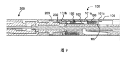
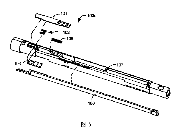
<負荷ユニットの型を識別するための認識部100a>
図6に示すように、負荷ユニットの型を識別するための認識部100aは、長尺体アセンブリ100の外側シェル105内に摺動可能なように配置された第1の摺動部材101と、第1の摺動部材101と共に摺動するように作動され得る、第1の摺動部材101上に配置された第1のトリガ部材102と、長尺体アセンブリ100の外側シェル105内に取り付けられ、当該長尺体アセンブリ100に対して固定された第1の回路基板103と、第1の回路基板103からのフィードバック信号によって負荷ユニット200の型を判定するように構成されたコントローラと、を備える。第1の摺動部材101および第1の回路基板103の具体的な取り付け位置は固有のものではなく、第1の摺動部材および第1の回路基板は、長尺体アセンブリ100の外側シェル105に、または長尺体アセンブリ100の外側シェル105の内側のフレーム107に選択的に接続され得る。
<
6, the
第1の摺動部材101は負荷ユニット200と協働するように構成され、異なる型の負荷ユニット200は、軸方向挿入または周方向回転の装着および係止過程において、長尺体アセンブリ100の長手方向軸方向または周方向に沿って異なる所定の位置に摺動するように第1の摺動部材101をトリガし得るため、第1のトリガ部材102を異なる所定の位置に摺動させる。
The first sliding
具体的には、図4~図20および図24~図25は、負荷ユニット200の軸方向の挿入および装着動作によって負荷ユニットの型が認識される外科用器具の実施形態を示す。負荷ユニット200と協働することができる第1の摺動部材101は、長尺体アセンブリ100内に軸方向および摺動可能に配置される。異なる型の負荷ユニット200が挿入されると、第1の摺動部材101は長手方向軸方向の異なる所定の位置に摺動するようにトリガされるため、第1のトリガ部材102を異なる所定の位置に摺動させる。
Specifically, Figures 4-20 and 24-25 show an embodiment of a surgical instrument in which the type of loading unit is recognized by the axial insertion and mounting action of the
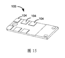
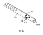
一実施形態では、図15に示されるように、少なくとも2つの第1の応答部材104が第1の回路基板103上に長手方向に離間して配置され、第1の摺動部材101は1つの第1のトリガ部材102を備える。第1の摺動部材101が負荷ユニット200によって作動されて所定の位置に長手方向に移動するとき、所定の位置は負荷ユニットの対応する型に依存し、第1のトリガ部材102は負荷ユニットの型に対応する電気信号を提供するように、対応する第1の応答部材104と協働する。別の実施形態では、図24に示されるように、少なくとも2つの第1のトリガ部材102が摺動部材101上に長手方向に離間して配置され、少なくとも2つの第1の応答部材104が第1の回路基板103上に周方向に離間して配置される。第1の摺動部材101が異なる型の負荷ユニット200の動作により長手方向軸方向の所定の位置まで摺動するとき、各第1の応答部材104は負荷ユニットの型に対応する電気信号を提供するように、対応する第1のトリガ部材102と協働するように構成される。例えば、第1の電気分岐A1は、第1の応答部材104を第1のトリガ部材102と協働させることによって導通または切断され、各第1の電気分岐A1上の負荷値は異なる。
In one embodiment, as shown in FIG. 15, at least two
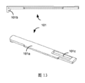
図3および図7~図9は、負荷ユニット200の型を識別するために使用される上記認識部100aの実施形態を示す。本実施形態において負荷ユニット200は3つの異なる型を有し、負荷ユニット200の型を特徴付けるための特徴部201が負荷ユニット200の近位側に配置される。特徴部201が認識作用面202を備え、認識作用面202が負荷ユニット200の所定の位置に配置され、所定の位置が負荷ユニット200の特定の型に対応する。
Figures 3 and 7-9 show an embodiment of the
このように、負荷ユニット200が長尺体アセンブリ100に挿入されるとき、特徴部201の認識作用面202は、第1の摺動部材101を、負荷ユニット200の型に対応した距離だけ摺動させる。例えば、図3に示すように、I型の負荷ユニット200の認識作用面202は、I型の負荷ユニットの近位端に最も近い位置に配置される。図8に示すように、I型の負荷ユニット200が長尺体アセンブリ100内に挿入されるとき、認識作用面202が第1の摺動部材101を押圧すことにより、第1のトリガ部材102を第1の所定位置まで摺動させ、第1のトリガ部材102が長尺体アセンブリ100の遠位側で第1の応答部材104と協働する。その結果、第1の応答部材104に接続された第1の電気分岐A1の状態が変化し、第1の回路基板103が第1の電気信号を取得し、第1の電気信号をコントローラに送信し、コントローラが、第1の電気信号によって負荷ユニット200がI型の負荷ユニット200であると判定する。
In this manner, when the
同様に、図7に示すように、II型の負荷ユニット200の認識作用面202は、II型の負荷ユニットの近位端から最も遠い位置に配置され、II型の負荷ユニット200が長尺体アセンブリ100に挿入されると、認識作用面202が第1の摺動部材101を押圧することにより、第1のトリガ部材102を第2所定位置に摺動させる。第1のトリガ部材102が長尺体アセンブリ100の近位端で第1の応答部材104と協働する結果、第1の応答部材104に接続された第1の電気分岐A1の状態が変化し、第1の回路基板103が第2電気信号を取得して第2電気信号をコントローラに送信し、コントローラが第2の電気信号によって負荷ユニット200がII型の負荷ユニット200であると判定する。
Similarly, as shown in FIG. 7, the
図9に示すように、コントローラはII型の負荷ユニット200を判定することができ、II型の負荷ユニットの特徴部201の認識作用面202は、最近位側と最遠位側との間に配置される。
As shown in FIG. 9, the controller can determine that the
第1の応答部材104が第1の回路基板103上に離間して配置されるため、第1のトリガ部材102の摺動中に、2つの第1の応答部材104の間に位置する第1のトリガ部材の一部から電気信号が出力されず、2つの第1の電気分岐A1間の負荷値の差を調整することによって、電気特性の幅が広い認識許容度が達成され得るため、認識システムの信頼性が改善される。
Since the
具体的には、第1の電気分岐A1の負荷は固有の位置に設定されておらず、例えば、抵抗器、ダイオード、インダクタ、能動負荷などが用いられてもよく、第1の回路基板103から出力される電気信号も異なる型を有し、例えば、電圧アナログ信号が用いられてもよく、周波数変調、振幅変調、キャパシタンス、インダクタンス、および他の電気信号も用いられてもよい。
Specifically, the load of the first electrical branch A1 is not set at a specific location, and for example, a resistor, a diode, an inductor, an active load, etc. may be used, and the electrical signal output from the
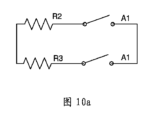
図10(a)~図10(c)は、負荷として抵抗器を有する負荷ユニット型認識回路D1を示している。具体的には一実施形態では図10aに示されるように、負荷ユニット型認識回路D1は2つの第1の電気分岐A1を並列に接続することによって形成され、2つの負荷ユニット200の型を区別するように構成され、一実施形態では図10bに示されるように、負荷ユニット型認識回路D1は、2つの第1の電気分岐A1と第1の負荷分岐A4とを並列に接続することによって形成され、2つの負荷ユニット200の型を区別するように構成される。
Figures 10(a) to 10(c) show a load unit type recognition circuit D1 having a resistor as a load. Specifically, in one embodiment, as shown in Figure 10a, the load unit type recognition circuit D1 is formed by connecting two first electrical branches A1 in parallel and configured to distinguish between two types of
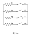
第1の負荷R4は第1の負荷分岐A4に接続されているため、負荷ユニット型認識回路D1は、常伝導回路を形成する。図10cに示すように、負荷ユニット型認識回路D1は、3つの第1の電気分岐A1と第1の負荷分岐A4とを並列に接続することによって構成され、3つの負荷ユニット200の型を区別するように構成されている。
Since the first load R4 is connected to the first load branch A4, the load unit type recognition circuit D1 forms a normal-conducting circuit. As shown in FIG. 10c, the load unit type recognition circuit D1 is configured by connecting three first electrical branches A1 and the first load branch A4 in parallel, and is configured to distinguish the types of the three
また、図10bに示すように、第1の負荷R4は第1の負荷分岐A4に接続されているため、負荷ユニット型認識回路D1は、負荷ユニット200が組み立てられているか否かの状態をセルフチェックするための常伝導回路を形成する。例えば、負荷ユニット200が組み立てられていないとき、第1の負荷分岐A4は導通状態にあるため、回路全体は導通状態にある。
Also, as shown in FIG. 10b, the first load R4 is connected to the first load branch A4, so that the load unit type recognition circuit D1 forms a normal-conducting circuit for self-checking the state of whether the
また、負荷ユニット200が組み立てられた後、例えば、III型の負荷ユニット200が組み立てられた後、認識作用面202が第1の摺動部材101に係合され、第1のトリガ部材102がその遠位端で第1の応答部材104と連続的に協働し、負荷ユニット200の型がコントローラによって判定される。別の型の負荷ユニット200が組み立てられるとき、例えば、I型の負荷ユニットまたはII型の負荷ユニットが組み立てられるとき、特徴部201の認識作用面202は第1の摺動部材101を両方押圧して、対応する第1の電気分岐A1を接続し、対応する認識電気信号を提供することができ、対応する負荷ユニットの型は、コントローラによって判定される。
Also, after the
一実施形態では、第1のトリガ部材102が第1の応答部材104と係合し、第1のトリガ部材102が第1の応答部材104と表面接触または線接触しているときに、第1の電気分岐A1が導通される。
In one embodiment, the first electrical branch A1 is conductive when the
第1のトリガ部材102は第1の応答部材104と面接触または線接触するように構成されているため、第1のトリガ部材102および第1の応答部材104の幅を調整することによって、より広い範囲の摺動が可能になる。その結果、認識システムの信頼性が向上する。
The
具体的には、第1の応答部材104は、異なる面積を有する認識情報間隔を備え、第1の応答部材104の領域が大きい場合、第1の応答部材104との接続が容易になるように、第1のトリガ部材102との第1の応答部材の接触面積が大きく、または第1のトリガ部材102がより大きい接触面積を有するように設定される。
Specifically, the
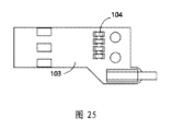
この2つの方法は、負荷ユニット型認識部100aの認識許容度を共に広くすることができるため、認識精度が向上する。図11および図12に示すように、第1の応答部材104は第1の回路基板103に配置された導電片104aとして設計され、第1のトリガ部材102は弾性導電シート102aとして設計され、第1のトリガ部材102の一端は第1の摺動部材101に係合され、第1のトリガ部材の他端は第1の回路基板103に当接する。弾性導電シート102aが第1の摺動部材101によって作動されて、導電片104aに当接する位置まで摺動したとき、導電片104aを有する第1の電気分岐A1が導通する。より具体的には図12および図15に示されるように、導電片104aは回路基板に対してわずかに突出しているかまたは窪んでいる正方形のシートとして形成することができる。図14に示すように、弾性導電シート102aは略V字状の挿入シート構造に形成され、第1のトリガ部材102の一端は第1の摺動部材101に挿入される。
These two methods can both widen the recognition tolerance of the load unit
具体的には、第1の摺動部材101の一方の板面には挿入口が設けられ、第1の摺動部材101の挿入口にはV字状の挿入シートの一方の面が挿入される。V字状の挿入シートの他方の面には外方に突出する円弧状の突出が設けられ、円弧状の突出が導電片104aと協働して線接触を実現するように構成されている。このように、円弧状の突出の幅を調整することにより、導電片104aとの接触面積を調整することができる。より具体的には、一実施形態では円弧状の突出の表面にシート状の導電性ラグが接続されることにより、弾性導電シート102aが導電片104aとの面接触を形成し、シート状の導電性ラグの大きさを調整することにより、導電片104aとの接触面積が調整される。
Specifically, an insertion opening is provided on one plate surface of the first sliding
第1の応答部材104と第1のトリガ部材102との間の接触面積を拡大するために、2つの第1のトリガ部材102が第1の摺動部材101に着脱可能に接続され、第1のトリガ部材102が第1の摺動部材101上に垂直な摺動方向に離間して配置され、2つの第1の応答部材104が第1の摺動部材101に垂直な摺動方向に第1の回路基板103上に配置され、各第1の応答部材104の位置が各第1のトリガ部材102の位置に対応するように配置される。この結果、2つの第1のトリガ部材102の各々がその対応する第1の応答部材104と係合したときに認識回路が導通する。別の実施形態では第1のトリガ部材102が第1の応答部材104と係合したときに第1の電気分岐A1が切断され、第1のトリガ部材102の長さが、2つの隣接する第1の応答部材104間の距離と一致する。この結果、第1のトリガ部材が異なる位置に移動したとき、1つの第1の応答部材104が位置する第1の電気分岐A1のみが切断される。他の導通された第1の電気分岐A1は対応する認識信号を生成する。
In order to enlarge the contact area between the
別の実施形態では、第1のトリガ部材102の長さは2つの隣接する第1の応答部材104の間の距離と一致するため、第1のトリガ部材が異なる位置に移動するときに複数の第1の電気分岐A1は同時に切断され得る。
In another embodiment, the length of the
例えば、第1のトリガ部材102は第1の所定の位置に移動するときに、第1のトリガ部材102は、第1の第1の応答部材104の第1の設定位置および第2の設定位置と協働し、2つの第1の電気分岐A1は同時に切断される。
For example, when the
第1のトリガ部材は第2の所定の位置に移動するときに第1の応答部材104の第2の設定位置および第3の設定位置と協働し、2つの第1の電気分岐A1は同時に切断され、他の電気分岐は組み合わされて、認識電気信号などを形成する。
When the first trigger member moves to the second predetermined position, it cooperates with the second and third set positions of the
図16~図18に示すように、第1の応答部材104は互いに当接する2つの弾性導電片104bを備え、2つの弾性導電片104bは電気的に接続されて1つの第1の電気分岐A1を形成し、
図17に示すように、第1のトリガ部材102は第1の摺動部材101に配置された絶縁突出102bであり、第1の摺動部材101が絶縁突出102bを駆動して、2つの弾性導電片104bの間の位置まで摺動させるとき、2つの弾性導電片104bが位置する第1の電気分岐A1が切断される。
As shown in FIGS. 16 to 18, the
As shown in FIG. 17, the
具体的には図16に示すように、長尺体アセンブリ100の軸方向の第1の回路基板103には並設された2つの制限板1031が形成され、2つの制限板1031の間に第1の応答部材104が取り付けられている。弾性導電片104bは各種の設計が可能である。一実施形態では、弾性導電片104bはV字状である。2つのV字状の弾性導電片104bの各々の一方の側板表面が制限板1031に当接し、2つのV字状弾性導電片の各々の他方の側板表面が互いに当接して電気的接続を形成する。2つの弾性導電片104bを確実に電気的に接続するために、V字状の弾性導電片104b(図18に示す)の一方の側板面に円弧状の突出が外方に形成されるため、2つのV字状の弾性導電片104bがより確実な線接触または面接触を形成する。
Specifically, as shown in FIG. 16, two limiting
第1のトリガ部材102が2つの第1の応答部材104の間の接続を円滑に切断するために、第1のトリガ部材102は近位端部(図17に示す)に鋭利な角構造を有する突出として形成されるため、近位端部の幅が狭くなり、第1のトリガ部材は2つのV字状の弾性導電片104aの間に容易に挿入され得、第1のトリガ部材102の本体部および鋭利な角部は円滑に通過する。第1のトリガ部材102が所定の位置まで摺動するとき、第1のトリガ部材102の本体部は第1の応答部材104と協働し、第1のトリガ部材102の少なくとも一部は信頼性のある切断を実現するために、非導電性材料から作製される。
In order for the
具体的には、図4および図6に示されるように、長尺体アセンブリ100は管状外側シェル105を備え、第1の摺動部材101は細長いシートとして形成され、管状外側シェル105の軸方向に摺動可能である。
Specifically, as shown in Figures 4 and 6, the
第1の摺動部材101を、1つの組み立てられた負荷ユニットなしに、長尺体アセンブリ100の近位端に付勢するために、第1の付勢部材106が長尺体アセンブリ100の外側シェル105と第1の摺動部材101との間に配置され、第1の付勢部材106がその遠位端に向かって第1の摺動部材101に力を加える。このように、第1の摺動部材101は第1の付勢部材106の作用により、長尺体アセンブリ100の遠位端に接近する初期状態で付勢されている。
In order to bias the first sliding
さらに、一実施形態では、図13に示すように、第1の摺動部材101と負荷ユニット200の認識作用面202との間の押圧作用を高めるために、第1の摺動部材101の近位端に突出101bが軸方向に配置され、第1の摺動部材101にリセット孔101cが長手方向に配置され、外側シェル105とリセット孔101cとの間に第1の付勢部材106が配置されている。具体的には図6に示すように、長尺体アセンブリ100の外側シェル105にフレーム107が配置され、フレーム107に摺動溝が配置され、摺動溝の底部に第1の回路基板103が固定接続される。摺動溝の側壁に第1の摺動部材101が摺動可能に接続され、摺動溝の近位端と第1の摺動部材101の近位端との間に第1の付勢部材106が配置される。
Furthermore, in one embodiment, as shown in FIG. 13, in order to enhance the pressing action between the first sliding
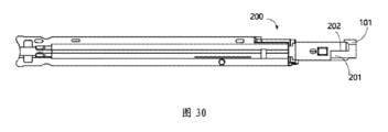
上述の実施形態における外科用器具において、図22に示すように、負荷ユニット200の近位端は、長尺体アセンブリ100と接続するための接続構造をさらに備え、近位端から遠位端に順次接続される第1の挿入区間205と第2の挿入区間206とを備える。第1の挿入区間205の外径は第2の挿入区間206の外径よりも大きく、第1の挿入区間205は長尺体アセンブリ100の遠位端とバヨネット式に解除可能に係合するための係合ナブ203を備える。
In the surgical instrument of the above embodiment, as shown in FIG. 22, the proximal end of the
第2の挿入区間206は、認識特徴部201として構成される。異なる型の負荷ユニット200は、異なる長さの第2の挿入区間206を有してもよく、第1の挿入区間205と第2の挿入区間206との間の段差が、第1の摺動部材101に当接し、当該段差が認識作用面202として構成される。
The
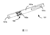
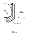
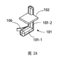
図26~図30は、バヨネット式における負荷ユニット200の係合の間に負荷ユニットの型が認識される外科用器具の実施形態を示す。負荷ユニット200と協働するように適合された第1の摺動部材101は、長尺体アセンブリ100の外側シェル105の内側に周方向に摺動可能に配置される。より具体的には、第1の摺動部材101が長尺体アセンブリ100の外側シェル105の内側にあるフレーム107上に摺動可能に配置され、第1の摺動部材101は長尺体アセンブリ100の周方向接線方向(すなわち、長尺体アセンブリ100の周方向で、長手方向軸に垂直な方向)に摺動可能である。あるいは第1の摺動部材101が長尺体アセンブリ100の外側シェル105内に摺動可能に配置され、第1の摺動部材101は長尺体アセンブリ100の外側シェル105の内壁の周方向に摺動可能である。第1のトリガ部材102を作動させて、異なる対応する所定の位置に摺動させるために、異なる型の負荷ユニット200は、第1の摺動部材101を作動させて、その回転中に、異なる対応する所定の位置に移動させる。これにより、組み立てられた負荷ユニット200の型情報は、その組み立ておよび回転中に識別され得る。
26 to 30 show an embodiment of a surgical instrument in which the type of the
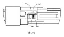
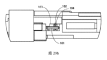
具体的には図26~図29に示されるように、少なくとも2つの第1の応答部材104が長尺体アセンブリ100の周方向接線方向に第1の回路基板103上に離間して配置され、第1の摺動部材101はL字状のスライダとして形成され、L字状のスライダは第1の支持アーム101-1および第2の支持アーム101-2を備え、第1の支持アーム101-1は負荷ユニットと協働するように構成され、第2の支持アーム101-2は第1のトリガ部材102を備える。長尺体アセンブリ100の周方向接線方向の異なる対応する所定の位置に移動させるために、第1の摺動部材101は各種の型の負荷ユニット200によって作動され得、対応する第1の応答部材104は第1のトリガ部材102と係合されて、負荷ユニットの型を表すことができる電気信号を提供する。例えば、第1の電気分岐A1は第1の応答部材104と第1のトリガ部材102との間の係合を通して導通または切断され、第1の電気分岐A1の各々は異なる負荷値を有し得る。図27は、第1の応答部材104と第1のトリガ部材102との協働を介して第1の電気分岐A1を導通させる概略構造図を示す。図29aおよび図29bは、第1の応答部材104と第1のトリガ部材102との協働を介して第1の電気分岐A1を切断する概略構造図を示す。
Specifically, as shown in FIGS. 26 to 29, at least two
この実施形態では第1の摺動部材101の摺動方向は他の実施形態とは異なり、回路を導通および切断する方法は第1の摺動部材101が軸方向に摺動する外科用器具の実施形態と同様であるが、本明細書では繰り返さない。
In this embodiment, the sliding direction of the first sliding
図27、図29aおよび図29bに示すように、第1の摺動部材101は長尺体アセンブリ100に配置されたフレーム107上に摺動可能に配置され、さらに、第1の摺動部材101とフレーム107との間に第1の付勢部材106が配置される。第1の付勢部材106は、長尺体アセンブリ100の周方向の接線方向、かつ、第1の摺動部材101上の第1の回路基板103から遠ざかる方向に力を加える。このように、第1の摺動部材101は第1の付勢部材106の作用により初期状態となるように、第1の回路基板103から遠位に摺動するように付勢されている。負荷ユニット200の長尺体アセンブリ100への係合中、第1の摺動部材101は負荷ユニット200の認識作用面202の作用により第1の付勢部材106の作用を克服するため、第1のトリガ部材102は第1の応答部材104と係合する。
27, 29a and 29b, the first sliding
本実施形態の外科用器具では、図30に示されるように、ノッチ構造が特徴部201として構成されるように、負荷ユニット200の近位端に配置され、負荷ユニット200が長尺体アセンブリ100と係合されるとき、第1の摺動部材101の第1の支持アーム101-1がノッチ内に挿入される。切欠きの切欠きアームは、軸方向に延びて、第1の摺動部材101の第1の支持アーム101-1と協働するための認識作用面202を形成する。また、上記一実施形態の外科用器具は、前記負荷ユニットが良好に組み立てられているか否かを判断する認識機構をさらに備え、前記負荷ユニットは前記負荷ユニットが良好に組み立てられていると判断された後にのみ作動されてもよい。これにより、負荷ユニットの誤組み立てによる医療事故が回避される。
In the surgical instrument of this embodiment, as shown in FIG. 30, a notch structure is arranged at the proximal end of the
具体的には図4に示すように、負荷ユニットが良好に組み立てられているかどうかを判定するための判定機構は判定部100bをさらに備える。判定部100bは、長尺体アセンブリ100内に配置され、さらなる外科手術を進めるかどうかを判定するために、判定部100bの判定に基づいて負荷ユニット200が良好に組み立てられているかどうかが判断される。
Specifically, as shown in FIG. 4, the determination mechanism for determining whether the load unit is properly assembled further includes a
別の実施形態では、判定部100bが回転ノブアセンブリ400またはハンドル部300に配置されてもよい。以下、負荷ユニット判定部100bの実施形態について説明する。図4は負荷ユニット判定部100bの実施形態を示し、負荷ユニット判定部100bはそれぞれ、長尺体アセンブリ100の外側シェル105内に摺動可能に配置された第2の摺動部材108および第3の摺動部材109を備え、第2の摺動部材108は、負荷ユニット200の係合ナブ203と協働するように構成され、第3の摺動部材109は、負荷ユニット200の近位端面204と協働するように構成される。負荷ユニット200が良好に挿入および回転されるとき、第2の摺動部材108は異なる設定位置まで摺動し、第3の摺動部材109は同じ設定位置まで摺動し、第2のトリガ部材110は第2の摺動部材108と接続され、第3のトリガ部材111は第3の摺動部材109と接続され、第2の回路基板112は長尺体アセンブリ100の外側シェル105内に固定配置される。第2の回路基板112には第2の応答部材113および第3の応答部材114が設けられている。
In another embodiment, the
第2の応答部材113は第2のトリガ部材110と協働して、第2の電気分岐A2を第1の状態と第2の状態との間で切り替えるように構成されている。第3の応答部材114は第3のトリガ部材111と協働して第3の電気分岐A3を第3の状態と第4の状態との間で切り替えるように構成される。負荷ユニット200が所定の位置に挿入され、回転される所定の位置に対応して、第2の回路基板112は、異なる状態を示す2つの信号を出力する。コントローラは負荷ユニット200が第2の回路基板112からのフィードバック信号によって、長尺体アセンブリ100に良好に組み立てられているかどうかを判定するように構成される。具体的には、第2の電気分岐A2の第1の状態および第2の状態は、異なる出力信号を有する2つの回路状態を指し、例えば、第1の状態は電気分岐の導通状態であり得、第2の状態は電気分岐の非導通状態または切断状態であり得る。あるいは第1の状態がV1の信号を出力するL1の負荷を有する電気分岐であってもよく、第2の状態はV2の信号を出力するL2の負荷を有する電気分岐であってもよい。同様に、第3の電気分岐A3の第3の状態および第4の状態は異なる出力信号を有する2つの回路状態を指し、ここでは繰り返さない。
The
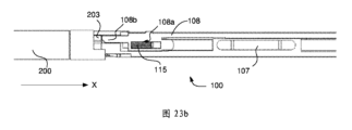
負荷ユニット200は、バヨネット式に長尺体アセンブリ100に取り付けられる。具体的には、図22に示すように、負荷ユニット200の係合ナブ203は、負荷ユニット200の端部に配置された係止突出として構成さる。係止摺動溝118は長尺体アセンブリ100の外側シェル105の内側に配置され、係止突出は負荷ユニット200の回転を防止するために、係止摺動溝118内に受容される。
The
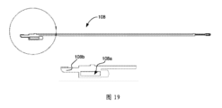
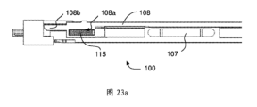
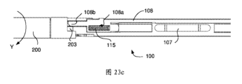
より具体的には、図19および図23aに示されるように、第2の摺動部材108は長尺体アセンブリ100内のフレーム107上に摺動可能に配置さる。係止部108bおよびリセット穴108aは、第2の摺動部材108の遠位端に配置され、リセット部材115は、長尺体アセンブリ100のリセット穴108aと外殻105との間に配置される。リセット部材115は、バネ、弾性シートまたはリードなどの付勢部材であり得る。図23bに示されるように、負荷ユニット200はX方向に沿って長尺体アセンブリ100内に挿入される。負荷ユニット200の係合ナブ203は、第2の摺動部材108を押圧して、近い側に向かって移動するため、係合ナブ203は係止摺動溝118の角に位置する。図23cに示されるように、負荷ユニット200はY方向に沿って回転され、係合ナブ203は第2の摺動部材108に向かうように移動し、第2の摺動部材108はリセット部材115の付勢力によりリセットされる。係合ナブ203は、第2の摺動部材108および係止摺動溝118の係止部の制限により、長尺体アセンブリ100内に係止される。
More specifically, as shown in FIG. 19 and FIG. 23a, the second sliding
負荷ユニット200は長尺体アセンブリ100にバヨネット式に取り付けられるため、負荷ユニット200は所定の位置に挿入された後に回転することによって長尺体アセンブリ100に組み立てられる。この結果、負荷ユニット200は所定の位置に挿入される位置と、所定の位置で回転される位置とを有する。負荷ユニットが所定の位置に挿入されているとき、負荷ユニット200の係合ナブ203は、第2の摺動部材108を押圧して、第2の摺動部材が第2の応答部材113と協働する位置に移動するため、第2の電気分岐A2の状態は例えば、非導通状態から導通状態に変更される。負荷ユニット200の近位端面204は、第3の摺動部材109を押圧して、第3の摺動部材が第3の応答部材114と協働する位置に移動するため、第3の電気分岐A3の状態は例えば、導通状態から非導通状態または負荷状態に変更される。このとき、第2の回路基板112は第1信号を出力し、例えば、第2の電気分岐A2は”1”の状態であり、第3の電気分岐A3は”0”の状態である。負荷ユニットが所定の位置で、回転される位置にあるとき、負荷ユニット200の係合ナブ203が回転されるため、負荷ユニットは、第2の摺動部材108から係合解除される。このとき、第2の摺動部材108は、第2の摺動部材が第2の応答部材113と協働しない位置に移動するため、第2の電気分岐A2の状態は例えば、導通状態から非導通状態または負荷状態に変更され、一方、負荷ユニット200の近位端面204の軸方向の位置は回転中、不変の状態であるため、第2の応答部材113との協働を維持し、第3の電気分岐A3の状態は不変の状態である。
Since the
このとき、第2の回路基板112は第2信号を出力し、例えば、第2の電気分岐A2は”0”の状態であり、第3の電気分岐A3は”0”の状態である。コントローラは、第2の回路基板112により出力される電気信号によって負荷ユニット200が良好に組み立てられたか否かを判断することができる。
At this time, the
また、第2の付勢部材115のため、負荷ユニット200が所定の位置で回転される位置にあるとき、第2のトリガ部材110および第2の応答部材113は確実に係合解除され得、第2の付勢部材115は遠位端に向かう力を第2の摺動部材108に加える。負荷ユニット200が所定の位置に挿入された位置にあるとき、負荷ユニット200の係合ナブ203は、第2の摺動部材108に当接し、第2のトリガ部材110が、第2の応答部材113をトリガして第2の電気分岐A2を第1の状態にする。負荷ユニット200が所定の位置に回転された位置にあるとき、第2の摺動部材108が第2の付勢部材115の作用により長尺体アセンブリ100の遠位端に移動し、第2のトリガ部材110が第2の応答部材113から係合解除されて第2の電気分岐A2を第2の状態にする。
Also, due to the
具体的には、負荷ユニット200が挿入されていない位置と、負荷ユニットが所定の位置に挿入されて所定の位置に回転された位置とを区別するために、すなわち、負荷ユニット200が長尺体アセンブリから解放された後に、負荷ユニット判定部を効果的にリセットすることができる。一実施形態では、第3の付勢部材116が第3の摺動部材109と長尺体アセンブリ100の外側シェル105との間に配置され、第3の摺動部材109を遠位方向に付勢する。負荷ユニット200が所定の位置に挿入された位置および所定の位置に回転された位置にあるとき、第3のトリガ部材111は第3の応答部材114をトリガして、第3の電気分岐A3を第1の状態に切り替える。負荷ユニット200が所定位置に挿入されていない位置にあるとき、第3の摺動部材116は第3の付勢部材109の作用により長尺体アセンブリ100の遠位端に移動し、第3のトリガ部材111は、第3の応答部材114から係合解除されて、第3の電気分岐A3を第2の状態に切り替える。このように、負荷ユニット200が挿入されていない所定の位置、挿入されている所定の位置および回転されている所定の位置にあるとき、第2の回路基板112は異なる対応する信号を出力することができるため、コントローラは、負荷ユニットが良好に組み立てられているかどうかを判断する。
Specifically, in order to distinguish between a position where the
第2のトリガ部材110と第2の応答部材113との間の協働および第3のトリガ部材111と第3の応答部材114との間の協働は、固有のものではなく、以下の実施形態で説明する。一実施形態では第2の応答部材113および第3の応答部材114が電気スイッチとして構成される。オン状態およびオフ状態を変更するために電気スイッチを切り替えることにより、第2のトリガ部材110は、第2の電気分岐A2の状態を変更し、第3のトリガ部材111は第3の電気分岐A3の状態を変更する。
The cooperation between the
より具体的には、第2の応答部材113が第1の電気スイッチとして構成される。第2のトリガ部材110が第2の応答部材113に当接する位置まで摺動するとき、第1電気スイッチの状態が切り替わるため(例えば、導通状態から非導通状態または負荷状態に切り替わる)、第2の電気分岐A2が第1状態となる。第2のトリガ部材110が第2の応答部材113から離間する位置まで摺動するとき、第1電気スイッチの状態が切り替わるため(例えば、非導通状態または負荷状態から導通状態に切り替わる)、第2の電気分岐A2が第2状態となる。第3のトリガ部材111が第3の応答部材114に当接する位置まで摺動するとき、第2の電気スイッチの状態が切り替わるため(例えば、導通状態から非導通状態または負荷状態に切り替わる)、第3の電気分岐A3が第3の状態に切り替わる。第3のトリガ部材111が、第3の応答部材114から係合解除する位置まで摺動するとき、第2の電気スイッチの状態が切り替わるため(例えば、導通状態から非導通状態または負荷状態に切り替わる)、第3の電気分岐A3が第4の状態に切り替わる。より具体的には、電気スイッチが押圧型電気スイッチとして構成され、第2のトリガ部材110または第3のトリガ部材111が押圧型電気スイッチの位置まで摺動するとき、電気スイッチの状態が押圧によって変更され、第2のトリガ部材または第3のトリガ部材が押圧型電気スイッチの位置から解放されると、電気スイッチの状態が再び変更される。
More specifically, the
あるいは別の実施形態では第2の応答部材113/第3の応答部材114が電気接点として構成され、第2のトリガ部材110は第2の応答部材113と協働して、第2の電気分岐A2を導通または切断/負荷するためのスイッチを形成し、第3のトリガ部材111は第3の応答部材114と協働して、第2の電気分岐A2を導通または切断/負荷するためのスイッチを形成する。より具体的には、第2のトリガ部材110が第2の応答部材113に当接する位置まで摺動するとき、第2のトリガ部材110および電気接点が第2の電気分岐A2を導通する。第2のトリガ部材110が第2の応答部材113から係合解除される位置まで摺動するとき、第2の電気分岐A2が非導通状態または負荷状態に切り替えられる。第3のトリガ部材111が第3の応答部材114に当接する位置まで摺動するとき、第3のトリガ部材111および電気接点は第3の電気分岐A3を導通する。第3のトリガ部材111が第3の応答部材114から係合解除される位置まで摺動するとき、第3の電気分岐A3は、非導通状態または負荷状態に切り離される/切り換えられる。
Alternatively, in another embodiment, the
負荷ユニット型認識部100aと負荷ユニット判定部100bの検出回路の構造は固有のものではない。一実施形態では、複数の第1の電気分岐A1が並列に接続されて負荷ユニット型認識回路D1を形成し、第2の電気分岐A2および第3の電気分岐A3が並列に接続されて認識回路D2が良好に組み立てられた負荷ユニットを形成する。負荷ユニット型認識回路D1と認識回路D2が良好に組み立てられた負荷ユニットは、互いに独立して設定され、それぞれコントローラに電気的に接続される。
The structure of the detection circuit of the load unit
負荷ユニット型認識部100aおよび負荷ユニット判定部100bの検出回路を簡略化するために、別の実施形態では、複数の第1の電気分岐A1が並列に接続されて負荷ユニット型認識回路D1を形成し、第2の電気分岐A2および第3の電気分岐A3が直列に接続されて認識回路D2が良好に組み立てられた負荷ユニットを形成する。負荷ユニット型認識回路D1および認識回路D2が良好に組み立てられた負荷ユニットは、電気ループを形成するためにコントローラに直列に接続される。より具体的には、負荷ユニット型認識回路D1は、第1の電気分岐A1と並列に接続された第1の負荷分岐A4をさらに備える。認識回路D2が良好に組み立てられた負荷ユニットにおいて、第2の電気分岐A2の第1の状態および第2の状態は異なる負荷値を有する2つの電気分岐に対応し、第3の電気分岐A3の第3の状態および第4の状態は電気分岐に接続し、電気分岐を切断または変更(負荷の増加)することに対応する。
In order to simplify the detection circuits of the load unit
負荷ユニット200が所定の位置に挿入されていない位置、および所定の位置に回転されている位置にあるとき、負荷ユニット型認識回路D1と認識回路D2が良好に組み立てられた負荷ユニットは導通状態であり、2つの状態における負荷値は異なり、コントローラは、回路全体の負荷値によって負荷ユニット200の状態を判定する。負荷ユニット200が所定の位置に挿入された位置にあるとき、負荷ユニット型認識回路D1および認識回路D2が良好に組み立てられた負荷ユニットは、非導通状態または負荷状態にある。
When the
具体的には図21a~図21cは、負荷ユニット型認識回路D1および認識回路D2が良好に組み立てられた負荷ユニットが直列に接続された一実施形態を示す。第2の電気分岐A2では第1の状態の負荷値がR1であり、第2の状態の負荷値が0であり、第3の電気分岐A3では第3の状態が導通状態であり、第4の状態が非導通状態である。負荷ユニット型認識回路D1は、並列に接続された2つの第1の電気分岐A1と、負荷値R4を有する1つの第1の負荷分岐A4とを備える。 Specifically, Figs. 21a-c show an embodiment in which the load unit type recognition circuit D1 and the recognition circuit D2 are well assembled load units connected in series. In the second electrical branch A2, the first state has a load value of R1, the second state has a load value of 0, and in the third electrical branch A3, the third state is a conducting state and the fourth state is a non-conducting state. The load unit type recognition circuit D1 comprises two first electrical branches A1 connected in parallel and one first load branch A4 with a load value R4.
図21aに示すように、負荷ユニット200が挿入されていない位置にあるとき、第2の電気分岐A2は第1の状態にあり、第3の電気分岐A3は第3の状態にあり、負荷ユニット型認識回路D1は第1の負荷分岐A4を介して導通状態にある。したがって、電気ループ全体は導通状態にあり、第2の電気分岐A2の負荷R1および第1の負荷分岐A4の負荷R4に基づいて、出力電気信号はA1である。
As shown in FIG. 21a, when the
図21bに示すように、負荷ユニット200が所定の位置に挿入された位置にあるとき、第2の電気分岐A2が第2の状態に切り換えられ、第3の電気分岐A3が第4の状態に切り換えられるため、電気ループ全体が非導通状態になり、コントローラは電気信号を受信することができない。
As shown in FIG. 21b, when the
図21cに示すように、負荷ユニット200が所定の位置に回転された位置にあるとき、第2の電気分岐A2は再び第1の状態に切り換えられ、第3の電気分岐A3は第3の状態に切り換えられる。負荷ユニット型認識回路D1において、1つの第1の電気分岐A1が導通され、例えば、R2の負荷を有する第1の電気分岐A1が導通され、電気ループ全体が導通状態にあり、第2の電気分岐A2の負荷R1、第1の電気分岐A1の負荷R2および第1の負荷分岐A4の負荷R4に基づいて、出力電気信号はA2である。
As shown in FIG. 21c, when the
図31は負荷ユニット型認識回路D1および認識回路D2が良好に組み立てられた負荷ユニットが直列に接続された別の実施形態を示し、第2の電気分岐A2では、第1の状態の負荷値がR1であり、第2の状態の負荷値が「0」であり、第3の電気分岐A3では第3の状態の負荷値がR10であり、第4の状態の負荷値が「0」である。負荷ユニット型認識回路D1は、並列に接続された2つの第1の電気分岐A1と、負荷値R4を有する1つの第1の負荷分岐A4とを備える。本実施形態では、上記のような回路を採用することにより、回路全体が常時導通状態となり、対応する回路の負荷値を変化させることで各種の表示信号が形成され、良好な表示精度が得られる。 Figure 31 shows another embodiment in which the load unit of the load unit type recognition circuit D1 and the recognition circuit D2 are well assembled and connected in series, and in the second electrical branch A2, the load value of the first state is R1 and the load value of the second state is "0", and in the third electrical branch A3, the load value of the third state is R10 and the load value of the fourth state is "0". The load unit type recognition circuit D1 has two first electrical branches A1 connected in parallel and one first load branch A4 with a load value R4. In this embodiment, by adopting the above-mentioned circuit, the entire circuit is always in a conductive state, and various display signals are formed by changing the load value of the corresponding circuit, and good display accuracy is obtained.
具体的には、負荷ユニット200が挿入されていない位置にあるとき、第2の電気分岐A2は第1の状態にあり、第3の電気分岐A3は第3の状態にあり、負荷ユニット型認識回路D1は第1の負荷分岐A4を介して導通状態にある。したがって、電気ループ全体は導通状態にあり、第2の電気分岐A2の負荷R1、第3の電気分岐A3の負荷R10、および第1の負荷分岐A4の負荷R4に基づいて、出力電気信号はA1’である。
Specifically, when the
負荷ユニット200が所定の位置に挿入された位置にあるとき、第2の電気分岐A2が第2の状態に切り換えられ、第3の電気分岐A3が第4の状態に切り換えられる。負荷ユニット型認識回路D1では、1つの第1の電気分岐A1が接続され、例えば、R2の負荷を有する第1の電気分岐A1が接続され、電気ループ全体が導通状態にあり、電気ループ全体が導通状態にあり、第2の電気分岐A2の負荷0と、第3の電気分岐A3の負荷0と、第1の負荷分岐A4の負荷RXとに基づいて、出力電気信号がA2’である。
When the
負荷ユニット200が所定の位置に回転された位置にあるとき、第2の電気分岐A2は第1の状態に切り替わり、第3の電気分岐A3は第3の状態に切り替わる。負荷ユニット型認識回路D1は導通状態のままであり、第2の電気分岐A2の負荷R1、第1の電気分岐A1の負荷R2および第1の負荷分岐A4の負荷RXに基づいて、出力電気信号はA3’である。
When the
上記実施形態では、負荷部200が挿入されていないときに、負荷ユニット型認識回路D1および認識回路D2が良好に組み立てられた負荷ユニットが導通状態となるため、外科用器具がセルフチェック状態となる。負荷ユニット200が良好に組み立てられているとき、負荷ユニット型認識回路D1および認識回路D2が良好に組み立てられた負荷ユニットは導通状態にあり、負荷ユニットが挿入されていないときとは異なる出力信号を有する。コントローラは負荷ユニット200が良好に組み立てられていることを判定し、当該信号によって負荷ユニット200の型を認識することができる。
In the above embodiment, when the
具体的には、第2の摺動部材108と第2のトリガ部材110との間の接続が固有のものではない。一実施形態では、第2の摺動部材が隆起接続状態にあり、第2のトリガ部材が挿入様式であり、第2の摺動部材108は細長い棒として形成され、挿入穴が第2の摺動部材の近位端部に配置され、挿入穴に挿入される挿入ロッドが第2のトリガ部材110上に配置される。より具体的には長尺体アセンブリ100の外側シェル105が開口部を備え、第2のトリガ部材110は、開口部を貫通する。図20に示すように、第2のトリガ部材110はトリガ本体1101と、スライダ1102と、挿入ロッド1103と、トリガロッド1104とを備える。トリガ本体1101は長尺体アセンブリ100の外側シェル105と固定接続され、滑斜面がトリガ本体1101上に配置され、スライダ1102は滑斜面に沿ってトリガ本体1101に摺動可能に接続され、長尺体アセンブリ100の外側シェル105の外側に位置する。挿入ロッド1103は、スライダ1102の遠位端に接続され、挿入により第2の摺動部材108に接続されるように構成されている。トリガロッド1104は、スライダ1102の近位端に接続され、第2の応答部材113をトリガするように構成される。より具体的には、トリガロッド1104には摺動中に第2の応答部材113を押圧するための突出が設けられている。
Specifically, the connection between the second sliding
具体的には、第3の摺動部材109および第3のトリガ部材111の間の接続が固有のものではない。一実施形態では、第3の摺動部材109が細長いチューブに形成され、長尺体アセンブリ100の近位端に位置する第3のトリガ部材111と直接接続される。別の実施形態では、図4に示されるように、第3の摺動部材109が形成され、中間連結部材117を介して第3のトリガ部材111と接続される。より具体的には第3の摺動部材109は細長いシートに形成され、長尺体アセンブリ100の遠位端に位置する。中間連結部材117は中空フレーム107を貫通するスリーブに形成され、第3のトリガ部材111はブロックに形成され、長尺体アセンブリ100の近位端に位置する。第3のトリガ部材111には、摺動中に第3の応答部材114を押圧するための突出が設けられている。
Specifically, the connection between the third sliding
具体的には外科用器具が表示ユニットをさらに備え、表示ユニットは負荷ユニット200の型を表示するように構成される。コントローラが第1の回路基板103によって提供される電気信号によって負荷ユニット200の型を判定した後、表示ユニットは、現在組み立てられている負荷ユニット200の型の外科用器具をユーザに示す表示を与えるように制御される。表示ユニットは、負荷ユニット200が良好に組み立てられているかどうかを表示するようにも構成され、コントローラは表示ユニットに、負荷ユニット200が第2の回路基板112からのフィードバック信号によって良好に組み立てられていることを示す第2の信号を送信させる。表示ユニットの具体的な表示方法および実施構造は、固有のものではなく、音声表示、機械的表示、表示灯表示またはテキスト表示を採用することができる。この結果、インジケータユニットは、ブザー、突出/陥没インジケータ、発光ダイオード、または表示画面などのハードウェア構造によって実現されてもよい。また、表示ユニットはユーザが表示信号を受信することを容易にするために、外科用器具のハンドル部300に取り付けられてもよい。
Specifically, the surgical instrument further includes a display unit, and the display unit is configured to display the type of the
明らかに、上記の実施形態は、本開示を明確に説明するための例に過ぎず、本開示の実施を限定することを意図するものではない。当業者であれば、上記の説明に基づいて、他の異なる形態の変更または変形例を実施することができる。本明細書の全ての実施を使い尽くすことは、必ずしも必要とせずまたは可能である。また、上記の実施形態に由来する明らかな変更または変形例は、本開示の保護の範囲内に依然として含まれる。
Obviously, the above embodiment is merely an example for clearly explaining the present disclosure, and is not intended to limit the implementation of the present disclosure. Those skilled in the art can implement other different forms of modifications or variations based on the above description. It is not necessary or possible to exhaust all the implementations of the present specification. In addition, obvious modifications or variations derived from the above embodiment are still included in the scope of protection of the present disclosure.
Claims (25)
前記ハンドルアセンブリはハンドル部と長尺体アセンブリとを備え、
前記長尺体アセンブリは、前記負荷ユニットの型を識別するための認識部を備え、
前記認識部は、
前記長尺体アセンブリの外側シェル内に摺動可能に配置された第1の摺動部材であって、所定の位置に移動するために、前記負荷ユニットの組み立て中に前記負荷ユニットによって作動するように構成される第1の摺動部材と、
前記第1の摺動部材とともに前記所定の位置に移動されるように適合され、前記第1の摺動部材上に配置された第1のトリガ部材と、
前記長尺体アセンブリの外側シェル内に配置された第1の回路基板であって、少なくとも2つの第1の応答部材が前記第1の回路基板上に配置され、当該第1の応答部材の各々が前記第1のトリガ部材と協働して、1つの第1の電気分岐を導通または切断するように構成され、前記第1の電気分岐の各々が異なる負荷値を有する第1の回路基板と、
前記第1の回路基板からのフィードバック信号によって前記負荷ユニットの型を判定するように構成されたコントローラと、を有する、外科用器具。 a handle assembly adapted to be attached to a load unit, which may have a variety of types;
The handle assembly includes a handle portion and an elongate body assembly.
the elongated body assembly includes a recognition portion for identifying a type of the load unit;
The recognition unit is
a first sliding member slidably disposed within an outer shell of the elongate body assembly, the first sliding member configured to be actuated by the loading unit during assembly of the loading unit to move into a predetermined position;
a first trigger member disposed on the first slide member and adapted to be moved with the first slide member to the predetermined position;
a first circuit board disposed within an outer shell of the elongated body assembly, at least two first response members disposed on the first circuit board, each of the first response members configured to cooperate with the first trigger member to make or break one of the first electrical branches, each of the first electrical branches having a different load value;
a controller configured to determine the type of the load unit via a feedback signal from the first circuit board.
前記第1のトリガ部材が前記所定の位置に移動したときに係合するように、前記第1の回路基板上に少なくとも2つの第1の応答部材が離間して配置されている、請求項1に記載の外科用器具。 At least two first trigger members are disposed on the first sliding member at a distance from each other in a sliding direction of the first sliding member;
2. The surgical instrument of claim 1, wherein at least two first response members are spaced apart on the first circuit board for engagement when the first trigger member is moved to the predetermined position.
前記第1の摺動部材が前記弾性導電シートを駆動して、前記弾性導電シートが前記導電片に当接するように摺動すると、前記導電片が配置された前記第1の電気分岐が導通する、請求項5に記載の外科用器具。 the first response member is configured as a conductive piece disposed on the first circuit board, the first trigger member is configured as an elastic conductive sheet, one end of the first trigger member is connected to the first sliding member, and the other end of the first trigger member abuts against the first circuit board;
6. The surgical instrument of claim 5, wherein when the first sliding member drives the elastic conductive sheet to slide into contact with the conductive piece, the first electrical branch in which the conductive piece is disposed becomes conductive.
前記認識作用面の位置は前記負荷ユニットの型を表す、請求項1に記載の外科用器具。 a feature disposed proximal to the loading unit, the feature having a recognition surface adapted to cooperate with the recognition portion to identify a type of the loading unit;
The surgical instrument of claim 1 , wherein the position of the recognition surface is indicative of a type of the loading unit.
前記判定部は
長尺体アセンブリの外側シェル内にそれぞれ摺動可能に配置された第2の摺動部材および第3の摺動部材であって、前記第2の摺動部材は前記負荷ユニットの係合ナブと協働するように構成され、前記第3の摺動部材は前記負荷ユニットの近位部と協働するように構成され、前記負荷ユニットが良好に組み立てられたときに、前記第2の摺動部材は前記負荷ユニットの型に対応する設定位置まで移動するように作動され、前記第3の摺動部材は設定位置に移動するように作動される、第2の摺動部材および第3の摺動部材と、
前記第2の摺動部材と接続される第2のトリガ部材および前記第3の摺動部材と接続される第3のトリガ部材と、
前記長尺体アセンブリの外側シェル内に固定して配置された第2の回路基板であって、前記第2の回路基板は、第2の応答部材および第3の応答部材を備え、前記第2の応答部材は前記第2のトリガ部材と協働して第1の状態と第2の状態との間で第2の電気的分岐を切り替えるように構成され、前記第3の応答部材は前記第3のトリガ部材と協働して第3の状態と第4の状態との間で第3の電気的分岐を切り替えるように構成され、少なくとも2つの状態を表す信号が前記第2の回路基板によって提供され、当該2つの状態を表す信号は、前記負荷ユニットが所定の位置に挿入され、所定の位置で回転されることをそれぞれ示す、第2の回路基板と、
前記負荷ユニットが前記第2の回路基板からのフィードバック信号によって良好に組み立てられているかどうかを判定するように構成されたコントローラと、を備える、請求項1に記載の外科用器具。 A determination unit for determining whether the load unit is properly assembled is further provided,
the determining portion includes: a second sliding member and a third sliding member, respectively, slidably disposed within an outer shell of the elongated body assembly, the second sliding member configured to cooperate with an engagement nub of the load unit, the third sliding member configured to cooperate with a proximal portion of the load unit, and when the load unit is properly assembled, the second sliding member is actuated to move to a set position corresponding to a type of the load unit, and the third sliding member is actuated to move to a set position;
a second trigger member connected to the second sliding member and a third trigger member connected to the third sliding member;
a second circuit board fixedly disposed within an outer shell of the elongated body assembly, the second circuit board comprising a second response member and a third response member, the second response member configured to cooperate with the second trigger member to switch a second electrical branch between a first state and a second state, the third response member configured to cooperate with the third trigger member to switch a third electrical branch between a third state and a fourth state, and signals representing at least two states are provided by the second circuit board, the signals representing the two states respectively indicating that the load unit is inserted into a predetermined position and rotated into a predetermined position;
The surgical instrument of claim 1, comprising: a controller configured to determine whether the load unit is successfully assembled via a feedback signal from the second circuit board.
前記負荷ユニットが所定の位置に挿入されたとき、前記負荷ユニットの係合ナブが第2の摺動部材に当接し、前記第2のトリガ部材が前記第2の応答部材と係合して、前記第2の電気分岐を前記第1の状態に切り替え、前記負荷ユニットが所定の位置で回転されるとき、前記第2の摺動部材は、前記第2の付勢部材の作用により前記長尺体アセンブリの遠位部に付勢され、前記第2のトリガ部材は前記第2の電気分岐を前記第2の状態に切り替えるために、前記第2の応答部材から係合解除されている、請求項15に記載の外科用器具。 a second biasing member disposed between the second sliding member and an outer shell of the elongate body assembly;
16. The surgical instrument of claim 15, wherein when the loading unit is inserted into position, an engagement nub of the loading unit abuts a second sliding member and the second trigger member engages the second response member to switch the second electrical branch to the first state, and when the loading unit is rotated in position, the second sliding member is biased against a distal portion of the elongate body assembly by action of the second biasing member and the second trigger member is disengaged from the second response member to switch the second electrical branch to the second state.
前記認識回路が良好に組み立てられた負荷ユニットにおいて、前記第2の電気分岐の、前記第1の状態および前記第2の状態は、異なる負荷値を有する2つの電気分岐に対応し、前記第3の電気分岐の、前記第3の状態および前記第4の状態は前記電気分岐の接続および前記電気分岐の切断に対応し、
前記負荷ユニットが挿入されていない位置および、所定の位置で回転される位置にあるとき、前記負荷ユニット型認識回路および前記認識回路が良好に組み立てられた負荷ユニットは導通状態にあり、前記2つの状態における前記負荷値は異なり、
前記負荷ユニットが所定の位置に挿入された位置にあるとき、前記負荷ユニット型認識回路および前記認識回路が良好に組み立てられた負荷ユニットは、非導通状態にある、請求項20に記載の外科用器具。 the load unit type recognition circuit further comprises a first load branch connected in parallel with the first electrical branch;
In a load unit in which the recognition circuit is successfully assembled, the first state and the second state of the second electrical branch correspond to two electrical branches having different load values, and the third state and the fourth state of the third electrical branch correspond to a connection of the electrical branch and a disconnection of the electrical branch;
When the load unit is in a non-inserted position and a rotated position at a predetermined position, the load unit type recognition circuit and the load unit with the recognition circuit properly assembled are in a conductive state, and the load values in the two states are different;
The surgical instrument of claim 20, wherein the load unit type recognition circuit and the load unit with the recognition circuit successfully assembled are in a non-conductive state when the load unit is in a predetermined inserted position.
前記認識回路が良好に組み立てられた負荷ユニットにおいて、前記第2の電気分岐の前記第1の状態および前記第2の状態は、異なる負荷値を有する2つの電気分岐に対応し、前記第3の電気分岐の前記第3の状態および前記第4の状態は異なる負荷値を有する2つの電気分岐に対応し、
前記負荷ユニットが挿入されていない位置にあるとき、前記負荷ユニットが所定の位置に挿入されている位置にあるとき、および前記負荷ユニットが所定の位置に回転される位置にあるとき、
前記負荷ユニット型認識回路および前記認識回路が良好に組み立てられた負荷ユニットは導通状態にあり、前記2つの状態における負荷値は異なる、請求項20に記載の外科用器具。 the load unit type recognition circuit further comprises a first load branch connected in parallel with the first electrical branch;
In a load unit in which the recognition circuit is successfully assembled, the first state and the second state of the second electrical branch correspond to two electrical branches having different load values, and the third state and the fourth state of the third electrical branch correspond to two electrical branches having different load values;
when the load unit is in an uninserted position, when the load unit is in an inserted position, and when the load unit is in a rotated position;
The surgical instrument of claim 20, wherein the load unit type recognition circuit and the load unit with the recognition circuit successfully assembled are in a conductive state, and the load values in the two states are different.
前記第1の挿入区間の外径は前記第2の挿入区間の外径よりも大きく、前記係合ナブは前記第1の挿入区間上に配置され、前記第1の挿入区間と前記第2の挿入区間との間に形成された段差は、前記第1の摺動部材と係合されるように適合され、前記第2の挿入区間の端面は、前記第3の摺動部材と係合されるように適合され、前記第2の挿入は前記負荷ユニットの型に関連する長さを有する、請求項15に記載の外科用器具。 The end of the loading unit includes a first insertion section and a second insertion section connected in sequence from a distal end to a proximal end,
16. The surgical instrument of claim 15, wherein an outer diameter of the first insertion section is larger than an outer diameter of the second insertion section, the engagement nub is disposed on the first insertion section, a step formed between the first insertion section and the second insertion section is adapted to be engaged with the first sliding member, an end face of the second insertion section is adapted to be engaged with the third sliding member, and the second insertion section has a length related to a type of the loading unit.
Priority Applications (1)
| Application Number | Priority Date | Filing Date | Title |
|---|---|---|---|
| JP2025175208A JP2026016484A (en) | 2021-07-29 | 2025-10-17 | surgical instruments |
Applications Claiming Priority (3)
| Application Number | Priority Date | Filing Date | Title |
|---|---|---|---|
| CN202110865511.XA CN113397616B (en) | 2021-07-29 | 2021-07-29 | Surgical instrument |
| CN202110865511.X | 2021-07-29 | ||
| PCT/CN2022/106013 WO2023005693A1 (en) | 2021-07-29 | 2022-07-15 | Surgical instrument |
Related Child Applications (1)
| Application Number | Title | Priority Date | Filing Date |
|---|---|---|---|
| JP2025175208A Division JP2026016484A (en) | 2021-07-29 | 2025-10-17 | surgical instruments |
Publications (1)
| Publication Number | Publication Date |
|---|---|
| JP2024528126A true JP2024528126A (en) | 2024-07-26 |
Family
ID=77687879
Family Applications (2)
| Application Number | Title | Priority Date | Filing Date |
|---|---|---|---|
| JP2024505542A Pending JP2024528126A (en) | 2021-07-29 | 2022-07-15 | Surgical Instruments |
| JP2025175208A Pending JP2026016484A (en) | 2021-07-29 | 2025-10-17 | surgical instruments |
Family Applications After (1)
| Application Number | Title | Priority Date | Filing Date |
|---|---|---|---|
| JP2025175208A Pending JP2026016484A (en) | 2021-07-29 | 2025-10-17 | surgical instruments |
Country Status (5)
| Country | Link |
|---|---|
| US (1) | US12490987B2 (en) |
| EP (1) | EP4378397B1 (en) |
| JP (2) | JP2024528126A (en) |
| CN (2) | CN115670539B (en) |
| WO (1) | WO2023005693A1 (en) |
Families Citing this family (4)
| Publication number | Priority date | Publication date | Assignee | Title |
|---|---|---|---|---|
| CN115670539B (en) * | 2021-07-29 | 2025-11-28 | 天津瑞奇外科器械股份有限公司 | Surgical instrument |
| CN113729524B (en) * | 2021-09-18 | 2025-11-21 | 浙江田螺云厨科技有限公司 | Cutter identification mechanism, electric cooker and replaceable part identification mechanism |
| CN116849742B (en) * | 2023-07-31 | 2025-11-04 | 无锡贝恩外科器械有限公司 | An electric stapler capable of recognizing at least four staple cartridge assemblies |
| CN121287216A (en) * | 2024-07-08 | 2026-01-09 | 江苏风和医疗器材股份有限公司 | Surgical instruments |
Citations (5)
| Publication number | Priority date | Publication date | Assignee | Title |
|---|---|---|---|---|
| JPS5940603U (en) * | 1982-09-08 | 1984-03-15 | 三菱重工業株式会社 | hydraulic cylinder |
| JP2000046502A (en) * | 1998-07-24 | 2000-02-18 | Honda Motor Co Ltd | Relative displacement detector |
| JP2008064208A (en) * | 2006-09-07 | 2008-03-21 | Tokutake Seisakusho:Kk | Cylinder device with stroke detection function |
| JP2011019904A (en) * | 2009-07-14 | 2011-02-03 | Tyco Healthcare Group Lp | End effector identification by mechanical feature |
| JP2015537187A (en) * | 2012-12-20 | 2015-12-24 | オリンパス株式会社 | Position detection sensor and manipulator |
Family Cites Families (19)
| Publication number | Priority date | Publication date | Assignee | Title |
|---|---|---|---|---|
| US20090090763A1 (en) * | 2007-10-05 | 2009-04-09 | Tyco Healthcare Group Lp | Powered surgical stapling device |
| US20110006101A1 (en) * | 2009-02-06 | 2011-01-13 | EthiconEndo-Surgery, Inc. | Motor driven surgical fastener device with cutting member lockout arrangements |
| US7464849B2 (en) * | 2006-01-31 | 2008-12-16 | Ethicon Endo-Surgery, Inc. | Electro-mechanical surgical instrument with closure system and anvil alignment components |
| US7753246B2 (en) * | 2007-01-31 | 2010-07-13 | Tyco Healthcare Group Lp | Surgical instrument with replaceable loading unit |
| US7793812B2 (en) * | 2008-02-14 | 2010-09-14 | Ethicon Endo-Surgery, Inc. | Disposable motor-driven loading unit for use with a surgical cutting and stapling apparatus |
| US7913891B2 (en) * | 2008-02-14 | 2011-03-29 | Ethicon Endo-Surgery, Inc. | Disposable loading unit with user feedback features and surgical instrument for use therewith |
| US9421014B2 (en) * | 2012-10-18 | 2016-08-23 | Covidien Lp | Loading unit velocity and position feedback |
| US10478182B2 (en) * | 2012-10-18 | 2019-11-19 | Covidien Lp | Surgical device identification |
| US9867612B2 (en) * | 2013-04-16 | 2018-01-16 | Ethicon Llc | Powered surgical stapler |
| US10175127B2 (en) * | 2014-05-05 | 2019-01-08 | Covidien Lp | End-effector force measurement drive circuit |
| US10251725B2 (en) * | 2014-06-09 | 2019-04-09 | Covidien Lp | Authentication and information system for reusable surgical instruments |
| US10561418B2 (en) * | 2014-06-26 | 2020-02-18 | Covidien Lp | Adapter assemblies for interconnecting surgical loading units and handle assemblies |
| US10729435B2 (en) * | 2015-11-06 | 2020-08-04 | Covidien Lp | Adapter assemblies for interconnecting surgical loading units and handle assemblies |
| US10338259B2 (en) * | 2015-12-14 | 2019-07-02 | Covidien Lp | Surgical adapter assemblies and wireless detection of surgical loading units |
| US10314579B2 (en) * | 2016-01-07 | 2019-06-11 | Covidien Lp | Adapter assemblies for interconnecting surgical loading units and handle assemblies |
| US10420551B2 (en) * | 2017-05-30 | 2019-09-24 | Covidien Lp | Authentication and information system for reusable surgical instruments |
| US11806015B2 (en) * | 2018-12-21 | 2023-11-07 | Intuitive Surgical Operations, Inc. | Surgical instruments having mechanisms for identifying and/or deactivating stapler cartridges |
| CN111759385B (en) * | 2020-07-17 | 2021-11-30 | 天津瑞奇外科器械股份有限公司 | Electric anastomat and loading unit thereof |
| CN115670539B (en) * | 2021-07-29 | 2025-11-28 | 天津瑞奇外科器械股份有限公司 | Surgical instrument |
-
2021
- 2021-07-29 CN CN202210905155.4A patent/CN115670539B/en active Active
- 2021-07-29 CN CN202110865511.XA patent/CN113397616B/en active Active
-
2022
- 2022-07-15 WO PCT/CN2022/106013 patent/WO2023005693A1/en not_active Ceased
- 2022-07-15 JP JP2024505542A patent/JP2024528126A/en active Pending
- 2022-07-15 EP EP22848298.0A patent/EP4378397B1/en active Active
-
2024
- 2024-01-26 US US18/424,494 patent/US12490987B2/en active Active
-
2025
- 2025-10-17 JP JP2025175208A patent/JP2026016484A/en active Pending
Patent Citations (5)
| Publication number | Priority date | Publication date | Assignee | Title |
|---|---|---|---|---|
| JPS5940603U (en) * | 1982-09-08 | 1984-03-15 | 三菱重工業株式会社 | hydraulic cylinder |
| JP2000046502A (en) * | 1998-07-24 | 2000-02-18 | Honda Motor Co Ltd | Relative displacement detector |
| JP2008064208A (en) * | 2006-09-07 | 2008-03-21 | Tokutake Seisakusho:Kk | Cylinder device with stroke detection function |
| JP2011019904A (en) * | 2009-07-14 | 2011-02-03 | Tyco Healthcare Group Lp | End effector identification by mechanical feature |
| JP2015537187A (en) * | 2012-12-20 | 2015-12-24 | オリンパス株式会社 | Position detection sensor and manipulator |
Also Published As
| Publication number | Publication date |
|---|---|
| WO2023005693A1 (en) | 2023-02-02 |
| EP4378397C0 (en) | 2025-12-31 |
| CN113397616A (en) | 2021-09-17 |
| CN113397616B (en) | 2022-09-06 |
| EP4378397B1 (en) | 2025-12-31 |
| US12490987B2 (en) | 2025-12-09 |
| CN115670539A (en) | 2023-02-03 |
| EP4378397A1 (en) | 2024-06-05 |
| EP4378397A4 (en) | 2024-11-13 |
| CN115670539B (en) | 2025-11-28 |
| US20240164781A1 (en) | 2024-05-23 |
| JP2026016484A (en) | 2026-02-03 |
Similar Documents
| Publication | Publication Date | Title |
|---|---|---|
| JP2024528126A (en) | Surgical Instruments | |
| US12029427B2 (en) | Methods and systems for performing circular stapling | |
| US9775607B2 (en) | Indicators for surgical staplers | |
| US11446025B2 (en) | Firing circuit for surgical stapler | |
| US11147559B2 (en) | Staple height indicator for powered surgical stapler | |
| US10265066B2 (en) | Surgical stapler with incomplete firing indicator | |
| JP6395289B2 (en) | Method and device for performing a surgical anastomosis | |
| CN106999189B (en) | Surgical stapling device with firing indicator | |
| US7963431B2 (en) | Grasping jaw mechanism | |
| US11116508B2 (en) | Electrical potential shifting circuit for powered surgical stapler | |
| JP2012000457A (en) | Staple position sensor system | |
| CN113518592B (en) | Circular surgical stapler | |
| US20200281592A1 (en) | Timer circuit to control firing of powered surgical stapler | |
| CN113543729B (en) | Power control circuit for electric surgical stapler | |
| CN111789651A (en) | Surgical suturing device |
Legal Events
| Date | Code | Title | Description |
|---|---|---|---|
| A521 | Request for written amendment filed |
Free format text: JAPANESE INTERMEDIATE CODE: A523 Effective date: 20240329 |
|
| A621 | Written request for application examination |
Free format text: JAPANESE INTERMEDIATE CODE: A621 Effective date: 20240329 |
|
| A977 | Report on retrieval |
Free format text: JAPANESE INTERMEDIATE CODE: A971007 Effective date: 20241120 |
|
| A131 | Notification of reasons for refusal |
Free format text: JAPANESE INTERMEDIATE CODE: A131 Effective date: 20241210 |
|
| A521 | Request for written amendment filed |
Free format text: JAPANESE INTERMEDIATE CODE: A523 Effective date: 20250307 |
|
| A02 | Decision of refusal |
Free format text: JAPANESE INTERMEDIATE CODE: A02 Effective date: 20250617 |