JP2024510058A - Collision avoidance using object contours - Google Patents
Collision avoidance using object contours Download PDFInfo
- Publication number
- JP2024510058A JP2024510058A JP2023512268A JP2023512268A JP2024510058A JP 2024510058 A JP2024510058 A JP 2024510058A JP 2023512268 A JP2023512268 A JP 2023512268A JP 2023512268 A JP2023512268 A JP 2023512268A JP 2024510058 A JP2024510058 A JP 2024510058A
- Authority
- JP
- Japan
- Prior art keywords
- vehicle
- determining
- bounding
- examples
- contour
- Prior art date
- Legal status (The legal status is an assumption and is not a legal conclusion. Google has not performed a legal analysis and makes no representation as to the accuracy of the status listed.)
- Pending
Links
- 238000000034 method Methods 0.000 claims abstract description 164
- 230000009471 action Effects 0.000 claims abstract description 34
- 238000005266 casting Methods 0.000 claims description 7
- 230000008569 process Effects 0.000 description 75
- 230000015654 memory Effects 0.000 description 27
- 238000004422 calculation algorithm Methods 0.000 description 16
- 238000010586 diagram Methods 0.000 description 15
- 238000004891 communication Methods 0.000 description 13
- 238000004458 analytical method Methods 0.000 description 10
- 230000006870 function Effects 0.000 description 10
- 230000003068 static effect Effects 0.000 description 8
- 238000003860 storage Methods 0.000 description 8
- 238000013528 artificial neural network Methods 0.000 description 7
- 238000004364 calculation method Methods 0.000 description 6
- 230000008859 change Effects 0.000 description 6
- 230000008447 perception Effects 0.000 description 6
- 241001465754 Metazoa Species 0.000 description 5
- 238000012790 confirmation Methods 0.000 description 5
- 238000005516 engineering process Methods 0.000 description 5
- 238000013527 convolutional neural network Methods 0.000 description 4
- 230000000694 effects Effects 0.000 description 4
- 238000010801 machine learning Methods 0.000 description 4
- 230000004044 response Effects 0.000 description 4
- 230000003936 working memory Effects 0.000 description 4
- 238000003491 array Methods 0.000 description 3
- 238000001514 detection method Methods 0.000 description 3
- 230000004807 localization Effects 0.000 description 3
- 238000013507 mapping Methods 0.000 description 3
- 238000012986 modification Methods 0.000 description 3
- 230000004048 modification Effects 0.000 description 3
- 238000012545 processing Methods 0.000 description 3
- 230000011218 segmentation Effects 0.000 description 3
- 238000012549 training Methods 0.000 description 3
- 230000001133 acceleration Effects 0.000 description 2
- 238000013459 approach Methods 0.000 description 2
- 238000003066 decision tree Methods 0.000 description 2
- 238000005259 measurement Methods 0.000 description 2
- 238000010238 partial least squares regression Methods 0.000 description 2
- 238000000513 principal component analysis Methods 0.000 description 2
- 238000012628 principal component regression Methods 0.000 description 2
- 238000006467 substitution reaction Methods 0.000 description 2
- 238000012706 support-vector machine Methods 0.000 description 2
- 230000003044 adaptive effect Effects 0.000 description 1
- 238000007792 addition Methods 0.000 description 1
- 230000002776 aggregation Effects 0.000 description 1
- 238000004220 aggregation Methods 0.000 description 1
- 230000006399 behavior Effects 0.000 description 1
- 239000003795 chemical substances by application Substances 0.000 description 1
- 239000003086 colorant Substances 0.000 description 1
- 230000000295 complement effect Effects 0.000 description 1
- 230000001010 compromised effect Effects 0.000 description 1
- 238000001816 cooling Methods 0.000 description 1
- 238000013135 deep learning Methods 0.000 description 1
- 238000009826 distribution Methods 0.000 description 1
- 230000007613 environmental effect Effects 0.000 description 1
- 239000012530 fluid Substances 0.000 description 1
- 238000009499 grossing Methods 0.000 description 1
- 230000003993 interaction Effects 0.000 description 1
- 238000012417 linear regression Methods 0.000 description 1
- 238000007477 logistic regression Methods 0.000 description 1
- 230000007774 longterm Effects 0.000 description 1
- 238000002156 mixing Methods 0.000 description 1
- 239000000203 mixture Substances 0.000 description 1
- 238000005457 optimization Methods 0.000 description 1
- 238000013488 ordinary least square regression Methods 0.000 description 1
- 230000000644 propagated effect Effects 0.000 description 1
- 238000007637 random forest analysis Methods 0.000 description 1
- 230000009467 reduction Effects 0.000 description 1
- 238000002310 reflectometry Methods 0.000 description 1
- 238000000926 separation method Methods 0.000 description 1
- 239000000725 suspension Substances 0.000 description 1
- 230000001360 synchronised effect Effects 0.000 description 1
- 230000001052 transient effect Effects 0.000 description 1
- 238000002604 ultrasonography Methods 0.000 description 1
- 238000010200 validation analysis Methods 0.000 description 1
- 230000000007 visual effect Effects 0.000 description 1
- XLYOFNOQVPJJNP-UHFFFAOYSA-N water Substances O XLYOFNOQVPJJNP-UHFFFAOYSA-N 0.000 description 1
Images


Classifications
-
- G—PHYSICS
- G08—SIGNALLING
- G08G—TRAFFIC CONTROL SYSTEMS
- G08G1/00—Traffic control systems for road vehicles
- G08G1/16—Anti-collision systems
- G08G1/165—Anti-collision systems for passive traffic, e.g. including static obstacles, trees
-
- G—PHYSICS
- G01—MEASURING; TESTING
- G01S—RADIO DIRECTION-FINDING; RADIO NAVIGATION; DETERMINING DISTANCE OR VELOCITY BY USE OF RADIO WAVES; LOCATING OR PRESENCE-DETECTING BY USE OF THE REFLECTION OR RERADIATION OF RADIO WAVES; ANALOGOUS ARRANGEMENTS USING OTHER WAVES
- G01S17/00—Systems using the reflection or reradiation of electromagnetic waves other than radio waves, e.g. lidar systems
- G01S17/88—Lidar systems specially adapted for specific applications
- G01S17/93—Lidar systems specially adapted for specific applications for anti-collision purposes
- G01S17/931—Lidar systems specially adapted for specific applications for anti-collision purposes of land vehicles
-
- G—PHYSICS
- G08—SIGNALLING
- G08G—TRAFFIC CONTROL SYSTEMS
- G08G1/00—Traffic control systems for road vehicles
- G08G1/16—Anti-collision systems
- G08G1/166—Anti-collision systems for active traffic, e.g. moving vehicles, pedestrians, bikes
Abstract
オブジェクトの輪郭を使用した衝突回避の技術について説明する。車両に関連付けられた軌道は、受信され得る。センサデータは、車両に関連付けられたセンサから受信できる。境界輪郭は、決定せれ、センサデータで表されるオブジェクトに関連付けることができる。軌道に基づいて、車両のシミュレートされた位置を決定することができる。さらに、境界輪郭の予測された位置を決定することができる。シミュレートされた車両の位置および境界輪郭の予測された位置に基づいて、車両とオブジェクトとの間の距離は、決定され得る。アクションは、車両とオブジェクトとの間の距離に基づいて、実行できる。A collision avoidance technique using object outlines will be explained. A trajectory associated with the vehicle may be received. Sensor data can be received from sensors associated with the vehicle. A boundary contour can be determined and associated with the object represented by the sensor data. Based on the trajectory, a simulated position of the vehicle can be determined. Furthermore, the predicted position of the boundary contour can be determined. Based on the simulated vehicle position and the predicted position of the boundary contour, a distance between the vehicle and the object may be determined. Actions can be performed based on the distance between the vehicle and the object.
Description
本発明は、オブジェクト輪郭を使用した衝突回避に関する。 The present invention relates to collision avoidance using object contours.
本特許出願は、2020年12月30日に出願された米国実用特許出願第17/138,710号および2020年12月30日に出願された米国実用特許出願第17/138,751号の優先権を主張する。出願番号17/138,710および17/138,751は、参照により本明細書に完全に組み込まれる。 This patent application is a priority application of U.S. Utility Patent Application No. 17/138,710, filed on December 30, 2020, and U.S. Utility Patent Application No. 17/138,751, filed on December 30, 2020. claim rights. Application numbers 17/138,710 and 17/138,751 are fully incorporated herein by reference.
車両は、環境を走行するときにオブジェクトに遭遇することがよくある。これらのオブジェクトは、他の車両、歩行者、動物などを含み得る。特定のオブジェクトを安全に通過しようとするとき、車両は、オブジェクトの位置、サイズ、および形状を決定し得る。いくつかの状況では、車両は、境界ボックスに基づいてオブジェクトのサイズおよび形状を決定し得る。しかしながら、境界ボックスは、オブジェクトの正確な表現を提供することができない場合がある。この障害は、オブジェクトを通過する車両の安全なナビゲーションが損なわれる可能性がある。 Vehicles often encounter objects as they drive through the environment. These objects may include other vehicles, pedestrians, animals, etc. When attempting to safely pass a particular object, a vehicle may determine the object's location, size, and shape. In some situations, a vehicle may determine the size and shape of an object based on a bounding box. However, bounding boxes may not provide an accurate representation of objects. This obstruction can impair safe navigation of a vehicle passing the object.
詳細な説明は、添付の図面を参照して説明される。図面において、参照番号の左端の数字は、その参照番号が最初に出現する図面を識別する。異なる図面における同一の参照番号の使用は、類似または同一のコンポーネントまたは特徴を示す。
本開示は、オブジェクトに関連付けられた境界輪郭を決定し、衝突回避などのアクションのためにそれらの境界輪郭を使用するための技術を対象とする。いくつかの例では、ライダーセンサは、オブジェクトに関連付けられたライダーデータを受信し得る。ライダーデータは、2次元平面に投影され得、凸包は、投影されたライダーデータに基づいて識別され得る。凸包に関連付けられた境界縁を取り除いて、オブジェクトにぴったりとフィットする周囲を表す境界輪郭を決定することができる。境界輪郭は、例えば、車両のプランニングコンポーネントで使用され、車両が境界輪郭によって表されるオブジェクトと衝突する可能性があるかどうかを決定することができる。 The present disclosure is directed to techniques for determining boundary contours associated with objects and using those boundary contours for actions such as collision avoidance. In some examples, a lidar sensor may receive lidar data associated with an object. Lidar data may be projected onto a two-dimensional plane, and a convex hull may be identified based on the projected lidar data. The bounding edges associated with the convex hull can be removed to determine a bounding contour that represents a close-fitting perimeter of the object. Boundary contours may be used, for example, in a vehicle planning component to determine whether a vehicle is likely to collide with an object represented by the boundary contour.
いくつかの例では、凸包の最長境界縁を置き換えるとき、最長境界縁は、第1のエンドポイントおよび第2のエンドポイントを有することができる。凸包内の内部点は、識別され得る。いくつかの例では、最長の境界縁は、1)第1のエンドポイントおよび内部点に基づく第1のセグメント、および2)内部点および第2のエンドポイントに基づく第2のセグメントに置き換えられ得る。更新された凸包は、第1のセグメントおよび第2のセグメントに基づいて決定され得る。最長の境界縁を連続的に置き換えるプロセスは、関連付けられたオブジェクトの周囲を密接に表す境界輪郭を生成することができる。 In some examples, when replacing the longest bounding edge of a convex hull, the longest bounding edge can have a first endpoint and a second endpoint. Interior points within the convex hull may be identified. In some examples, the longest bounding edge may be replaced with 1) a first segment based on a first endpoint and an interior point, and 2) a second segment based on an interior point and a second endpoint. . An updated convex hull may be determined based on the first segment and the second segment. The process of successively replacing the longest boundary edge can produce a boundary contour that closely represents the perimeter of the associated object.
いくつかの例では、センサデータは、ライダーデータを含むことができ、多様なライダー点を含むことができる。ライダーデータを2次元表現に投影することに関連して、すべてのライダー点のいくつかは、事前に定められたグリッド上の最も近い位置に再配置することができる。任意の2つまたはそれ以上のライダー点が同じグリッド位置を共有する場合、重複するライダー点の一部またはすべては、各グリッド位置に対して1つのライダー点が残るように削除することができる。いくつかの例では、所定のグリッド位置は、1センチメートルの間隔を有し得るが、本明細書では他の寸法が企図される。 In some examples, the sensor data can include lidar data and can include a variety of lidar points. In connection with projecting lidar data into a two-dimensional representation, some of all lidar points can be relocated to the closest position on a predetermined grid. If any two or more lidar points share the same grid location, some or all of the duplicate lidar points may be removed so that one lidar point remains for each grid location. In some examples, the predetermined grid locations may have a spacing of one centimeter, although other dimensions are contemplated herein.
いくつかの例では、システムは、オブジェクトに関連付けられた境界輪郭に基づいて、車両がオブジェクトと衝突する可能性があるかどうかを決定し得る。衝突の可能性が検出された場合、システムは、オブジェクトとの衝突を回避するための車両アクションを決定し、衝突を回避しようとするためにそのアクションを開始し得る。他の例では、アクションは、オブジェクトに関連付けられた境界輪郭に基づいて決定され得る。例えば、アクションは、車両を制御すること、静的オブジェクトを決定すること、動的オブジェクトを決定すること、またはマップデータを更新することのうちの少なくとも1つを含み得る。 In some examples, the system may determine whether a vehicle is likely to collide with an object based on a boundary contour associated with the object. If a potential collision is detected, the system may determine a vehicle action to avoid collision with the object and initiate that action to attempt to avoid the collision. In other examples, the action may be determined based on a bounding contour associated with the object. For example, the action may include at least one of controlling a vehicle, determining a static object, determining a dynamic object, or updating map data.
いくつかの例では、ライダー点クラウドデータで識別されたオブジェクトに関連付けられた境界ボックスが識別され得る。境界ボックスのサイズは、より多くの量のライダー点クラウドデータを含むように拡張される。拡張された境界ボックス内のライダー点は、キャプチャされ、オブジェクトに関連付けられた増加したライダーデータを提供することができる。拡張された境界ボックス内のすべてのライダー点に関連付けられた境界形状は、オブジェクトの輪郭をよりよく表すために作成され得る。 In some examples, bounding boxes associated with objects identified in the lidar point cloud data may be identified. The size of the bounding box is expanded to include a larger amount of lidar point cloud data. Lidar points within the expanded bounding box can be captured and provide increased lidar data associated with the object. A bounding shape associated with all lidar points within the expanded bounding box may be created to better represent the contour of the object.
いくつかの例では、システムは、車両に関連付けられた軌道を受信し、車両に関連付けられたセンサからセンサデータを受信し得る。境界輪郭を決定することができ、境界輪郭は、センサデータに表されるオブジェクトに関連付けられている。車両に関連付けられた軌道に基づいて、システムは、車両のシミュレートされた位置を決定し得る。さらに、境界輪郭の予測位置が決定され得る。車両のシミュレートされた位置および境界輪郭の予測された位置に基づいて、車両とオブジェクトとの間の距離が決定され得る。アクションは、車両とオブジェクトとの間の距離に基づいて実行することができる。 In some examples, the system may receive a trajectory associated with the vehicle and receive sensor data from sensors associated with the vehicle. A boundary contour may be determined, the boundary contour being associated with the object represented in the sensor data. Based on the trajectory associated with the vehicle, the system may determine a simulated position of the vehicle. Furthermore, a predicted position of the boundary contour may be determined. Based on the simulated position of the vehicle and the predicted position of the boundary contour, a distance between the vehicle and the object may be determined. Actions can be performed based on the distance between the vehicle and the object.
いくつかの例では、本明細書で説明する境界輪郭は、オブジェクトの周囲を密接に識別するポリゴンであり得る。車両とオブジェクトとの間の距離に基づいて実行されるアクションは、軌道を検証すること、または軌道を無効にすることを含み得る。いくつかの例では、車両とオブジェクトとの間の距離は、レイキャスティングを使用して決定され得る。例えば、レイキャスティングは、車両の側面から(または軌道に関連付けられた点から)境界輪郭に向かって(例えば、垂直に)拡張し得る。衝突は、光線が通過するいくつかの境界輪郭縁に基づいて検出することができる。例えば、光線が偶数の境界輪郭縁を通過する場合、衝突は、発生してない。しかし、光線が奇数の境界輪郭縁を通過すると、車両とオブジェクトの間で衝突が発生する。 In some examples, the bounding contours described herein may be polygons that closely identify the perimeter of an object. Actions performed based on the distance between the vehicle and the object may include validating the trajectory or invalidating the trajectory. In some examples, the distance between the vehicle and the object may be determined using ray casting. For example, ray casting may extend from the side of the vehicle (or from a point associated with the trajectory) toward the bounding contour (eg, vertically). Collisions can be detected based on some boundary contour edges through which the ray passes. For example, if a ray passes through an even number of boundary contour edges, no collision has occurred. However, if the ray passes through an odd number of boundary contour edges, a collision will occur between the vehicle and the object.
いくつかの例では、軸整列された境界ボックスを使用して、車両とオブジェクトとの間などの潜在的な衝突を迅速に確認することができる。例えば、軸整列された境界ボックスは、境界輪郭に関連付けられ得る。車両とオブジェクトとの間の第2の距離は、軸整列された境界ボックスに基づいて決定され得る。いくつかの例では、軸整列された境界ボックスは、車両の長手方向軸に沿って整列される。 In some examples, axis-aligned bounding boxes can be used to quickly identify potential collisions, such as between a vehicle and an object. For example, an axis-aligned bounding box may be associated with a bounding contour. A second distance between the vehicle and the object may be determined based on the axis-aligned bounding box. In some examples, the axis-aligned bounding box is aligned along the longitudinal axis of the vehicle.
本明細書で説明する技術は、多くの方法で車両のコンピューティングデバイスの機能を改善することができる。記載された技術は、オブジェクトの形状の改善された表現を提供する。本明細書に記載されるように、境界輪郭は、オブジェクトの周囲に密接に従うポリゴンを提供する。境界輪郭は、境界ボックスのように4つの側面に限定されない。したがって、境界輪郭は、オブジェクトの正確な表現を提供するために、オブジェクトのすべての形状に調整することができる。ぴったりフィットする境界輪郭は、潜在的な衝突、車両とオブジェクトとの間の距離、およびオブジェクトに関連付けられた他のアクションのより正確な決定をサポートする。 The techniques described herein can improve the functionality of a vehicle's computing device in many ways. The described technique provides an improved representation of the shape of an object. As described herein, a bounding contour provides a polygon that closely follows the perimeter of an object. Bounding contours are not limited to four sides like bounding boxes. Therefore, the boundary contour can be adjusted to all shapes of the object to provide an accurate representation of the object. Close-fitting boundary contours support more accurate determination of potential collisions, distances between vehicles and objects, and other actions associated with objects.
本明細書で説明する技術は、また、境界輪郭をより速く、より少ないコンピューティングリソースで決定することによって、車両のコンピューティングデバイスの改善された機能を提供し得る。ドロネー三角測量などの既存の技術と比較して、説明されるシステムおよび方法は、一組の点のすべての点をカバーする多様な三角形を作成する必要なしに境界輪郭の作成を簡素化し得る。点のセット内に多様な三角形を作成する必要があるドロネー三角測量プロセスは、時間がかかり、重要なコンピューティングリソースを必要とする可能性がある。本明細書で説明されるシステムおよび方法は、一組の点における三角形を計算する必要性を排除することによってプロセスを簡素化し得る。 The techniques described herein may also provide improved functionality for a vehicle's computing device by determining boundary contours faster and with fewer computing resources. Compared to existing techniques such as Delaunay triangulation, the described systems and methods may simplify the creation of boundary contours without the need to create diverse triangles that cover all points in a set of points. The Delaunay triangulation process, which requires creating a variety of triangles within a set of points, can be time consuming and require significant computing resources. The systems and methods described herein may simplify the process by eliminating the need to calculate triangles at a set of points.
本明細書で説明される本技術は、多くの手法で実装されることが可能である。例示的な実装は、下記の図面を参照して以下で提供される。自律車両の文脈で説明されているが、本明細書に記載される方法、装置、およびシステムは、様々なシステムに適用することができ、自律車両に限定されない。別の例では、技術は、任意のタイプの車両、ロボットシステム、またはセンサデータを使用する任意のシステムで利用することができる。また、本明細書において説明される技術は、(例えば、センサを使用して取り込まれた)実データ、(例えば、シミュレータによって生成された)シミュレートされたデータ、または、この2つの任意の組み合わせと共に使用されることが可能である。 The techniques described herein can be implemented in many ways. Example implementations are provided below with reference to the drawings below. Although described in the context of autonomous vehicles, the methods, apparatus, and systems described herein can be applied to a variety of systems and are not limited to autonomous vehicles. In another example, the technology can be utilized with any type of vehicle, robotic system, or any system that uses sensor data. Additionally, the techniques described herein may be applied to real data (e.g., captured using a sensor), simulated data (e.g., generated by a simulator), or any combination of the two. It can be used with
図1は、本開示の例による、オブジェクトに関連付けられた境界輪郭を決定し、境界輪郭を使用して、オブジェクトとの衝突の可能性について車両の軌道を確認するために、環境122および環境132に関連付けられた例示的なプロセス100の絵画的流れ図を示す。いくつかの例では、オブジェクトに関連付けられた境界輪郭を決定することは、本明細書で説明されるように、車両内の車両コンピューティングデバイスによって実行され得る。さらに、いくつかの例では、車両コンピューティングデバイスを使用して、境界輪郭に基づいて、オブジェクトとの衝突の可能性について車両の軌道を確認し得る。
FIG. 1 illustrates an
図1に示されるように、プロセス100は、車両に近接するオブジェクトに関連付けられた境界輪郭を決定する動作120を含む。プロセス100はさらに、オブジェクトに関連付けられた境界輪郭を使用して、オブジェクトとの衝突の可能性について車両の軌道を確認する動作130を含む。
As shown in FIG. 1,
環境122に示されるように、例示的な画像102は、オブジェクト104が動作し得る場面を示す。例示的な画像102において、オブジェクト104は、車両として示される。他の例では、オブジェクト104は、任意のタイプの静的オブジェクトまたは動的オブジェクトであり得る。例えば、静的オブジェクトは、木、建物、標識、交通信号などを含み得る。例示的な動的オブジェクトは、車両、歩行者、動物などを含み得る。いくつかの例では、オブジェクト104は、特定の時間(例えば、移動中の車両)で移動してもよく、他の時間(例えば、駐車中の車両または信号機で停止した車両)で停止してもよい。
As shown in
図1はまた、画像102内のオブジェクト104に関連付けられた境界輪郭106の例を示す。境界輪郭106は、例えば、本明細書で説明されるシステムおよび方法を使用して作成され得る。境界輪郭106は、オブジェクト104の外周に関連付けられ得る。本明細書で説明されるように、境界輪郭106は、オブジェクト104との衝突を回避し、オブジェクトから安全な距離を維持するために使用され得る。いくつかの例では、境界輪郭106は、境界ボックス(例えば、オブジェクト104に関連付けられた矩形ボックス)と組み合わせて使用することができ、これらの両方は、オブジェクト104に関連付けられた情報を提供し得る。
FIG. 1 also shows an example of a
いくつかの例では、境界輪郭106は、境界ボックスよりもオブジェクトの正確な形状のより良い表現を提供し得る。特定の例では、境界ボックスは、4つの辺を有する長方形であってもよい。この基本的な長方形の形状は、境界ボックスがオブジェクトのすべての部分を含むように拡張され得るため、オブジェクトを正確に表すことができない場合がある。例えば、大きなサイドミラーを有する車両の状況では、ミラーに合わせて拡張された境界ボックスは、実際の車両よりも著しく大きい場合がある。同様に、境界ボックスが大きなサイドミラーを有する車両の本体に合うようにサイズ設定されている場合、境界ボックスは、サイドミラーを包含しない場合がある。対照的に、境界輪郭106は、オブジェクトの形状または不規則性に関係なく、オブジェクトの外縁に密接に従うように作成されたポリゴンであり得る。このぴったりフィットされるポリゴンは、長方形の境界ボックスよりもオブジェクトの形状をより正確に表現を提供し得る。1つまたは複数の例では、境界輪郭106を表すポリゴンは、本明細書で「境界縁」とも呼ばれる5つ以上の外縁を有し得る。
In some examples, the bounding
いくつかの例では、境界輪郭106は、オブジェクト104との衝突の可能性について車両の軌道を確認するときに使用され得る。環境132に示されるように、軌道110は、環境132を通る車両112の計画された運転 経路を画定し得る。図1では、オブジェクトに関連付けられた境界輪郭114が、軌道110および車両112に対して表示される。境界輪郭114は、別の車両、歩行者、動物、建物、街路標識、木などの任意のオブジェクトタイプに関連付けられ得る。本明細書で説明されるように、記載されるシステムおよび方法は、光線116によって示されるように、レイキャスティングを使用して、車両112と境界輪郭114との間の距離を決定し得る。車両112と境界輪郭114との間の距離に基づいて、車両112は、境界輪郭114に関連付けられたオブジェクトとの衝突を回避するために1つまたは複数のアクションを取ることができる。例えば、車両112は、オブジェクトからの距離およびオブジェクトのタイプに関連付けられる潜在的なリスクに応じて、ステアリング、ブレーキ、ホーンの鳴り、車両乗員の警告などのアクションを取ることができる。
In some examples, bounding
本明細書で説明されるように、いくつかの例は、オブジェクトに関連付けられた境界輪郭を決定し、オブジェクトとの衝突の可能性について車両の軌道を確認し、車両内の車両コンピューティングデバイスを使用して他の活動を実行し得る。車両に関する追加の詳細が本明細書に記載される。 As described herein, some examples include determining a boundary contour associated with an object, checking the trajectory of the vehicle for potential collisions with the object, and using a vehicle computing device within the vehicle. may be used to perform other activities. Additional details regarding the vehicle are described herein.
図2は、本開示の例による、オブジェクトに関連付けられたセンサデータに基づいて、オブジェクトに関連付けられた境界輪郭を決定するための例示的なプロセス200を示すフローチャートである。プロセス200に関して本明細書で記載される動作は、本明細書で説明されるように、1つまたは複数の車両コンピューティングデバイスによって実行され得る。
FIG. 2 is a flowchart illustrating an
例として、プロセス200は、論理フローグラフとして示され、その各動作は、ハードウェア、ソフトウェア、またはそれらの組み合わせで実装することができる一連の動作を表す。ソフトウェアの場合において、動作は、1つまたは複数のプロセッサによって実行された場合に、列挙した動作を実行する1つまたは複数のコンピュータ可読記憶媒体に格納されたコンピュータ実行可能命令を表すことができる。一般に、コンピュータ実行可能命令は、特定の機能を実行するか、または特定の抽象データタイプを実装するルーティン、プログラム、オブジェクト、コンポーネント、データ構造などを含み得る。動作が記載される順序は、限定として解釈されることを意図するものではなく、プロセス200を実装するために、記載される動作の任意の数を任意の順序でおよび/または並行して結合(または省略)することができる。いくつかの例では、多様な分岐は、個別に、または本明細書で説明される他の動作と組み合わせて使用され得る代替の実装を表す。
As an example,
動作202において、プロセスは、オブジェクトを含む画像データを受信することを含み得る。いくつかの例では、画像データは、車両に関連付けられたイメージセンサ(例えば、カメラ)によってキャプチャされ得る。動作204において、プロセスは、画像データに基づいてオブジェクトに関連付けられた境界ボックスを決定することを含み得る。いくつかの例では、3次元境界ボックスは、画像データに基づいて決定され得る。3次元境界ボックスを決定するための例示的な技術は、2017年11月16日に出願された「Pose Determination from Contact Point」と題された米国特許出願第15/814,870号、および2019年5月9日に出願された「Image-Based Depth Data and Bounding Boxes」と題された米国特許出願第16/408,414号に説明されており、これらの両方の全体は、あらゆる目的のために、参照により本明細書に組み込まれる。しかしながら、境界ボックスは、ライダーデータ、飛行時間データなどの他のセンサデータに基づいて決定することができる。いくつかの例では、プロセス200は、動作202および204を省略し得る。
At act 202, the process may include receiving image data that includes an object. In some examples, image data may be captured by an image sensor (eg, a camera) associated with a vehicle. At act 204, the process may include determining a bounding box associated with the object based on the image data. In some examples, a three-dimensional bounding box may be determined based on image data. Exemplary techniques for determining three-dimensional bounding boxes are disclosed in U.S. Patent Application No. 15/814,870, entitled "Pose Determination from Contact Point," filed November 16, 2017, and published in 2019. No. 16/408,414, filed May 9, entitled "Image-Based Depth Data and Bounding Boxes," both of which are available in their entirety for all purposes , incorporated herein by reference. However, the bounding box can be determined based on other sensor data such as lidar data, time-of-flight data, etc. In some examples,
いくつかの例では、境界ボックスは、本明細書で説明されるように、ライダーセンサによってキャプチャされ得るライダーデータに基づいて決定され得る。この例では、動作202および204は、オブジェクトに関連付けられたライダーデータに基づいて境界ボックスを決定する動作に置き換えることができる。 In some examples, the bounding box may be determined based on lidar data that may be captured by a lidar sensor, as described herein. In this example, acts 202 and 204 may be replaced with an act of determining a bounding box based on lidar data associated with the object.
動作206において、プロセスは、オブジェクトに関連付けられたライダーデータを受信し得る。ライダーデータは、車両、構造、または任意の他のアイテムに関連付けられたライダーセンサから受信され得る。いくつかの例では、ライダーデータは、ライダーセンサによって識別される複数のライダー点を含む点群を含む。動作208において、プロセスは、オブジェクトに関連付けられた点群を決定し得る。オブジェクトに関連付けられた点群は、オブジェクトに具体的に関連付けられた全体的な点群のサブ領域(例えば、関心領域)を表し得る。いくつかの例では、ライダー点のサブセットは、オブジェクトを識別するインスタンスセグメンテーションに基づいて決定され得る。
At act 206, the process may receive lidar data associated with the object. Lidar data may be received from lidar sensors associated with a vehicle, structure, or any other item. In some examples, lidar data includes a point cloud that includes multiple lidar points identified by lidar sensors. At
動作210において、オブジェクトに関連付けられた点群は、実質的に水平な平面のような2次元平面上に投影され得る。動作212において、プロセスは、2次元平面上に投影された点群に基づいて、オブジェクトに関連付けられた境界輪郭を決定し得る。いくつかの例では、境界輪郭は、本明細書で説明されるように、境界輪郭を計画された車両軌道と比較する際に使用するために、車両プランニングコンポーネント(例えば、図12に示されるプランニングコンポーネント1232)に提供され得る。
In
1つまたは複数の例では、境界輪郭は、3次元表現に拡張され得る。例えば、2次元境界輪郭は、x-y平面内で画定されてもよい。2次元境界輪郭は、x-y平面に垂直なx軸に沿って境界輪郭を延長することによって、3次元表現に拡張することができる。いくつかの例では、2次元境界輪郭は、畳み込みニューラルネットワーク(CNN)を使用して3次元表現に拡張され得る。 In one or more examples, the boundary contour may be expanded into a three-dimensional representation. For example, a two-dimensional boundary contour may be defined in the xy plane. A two-dimensional boundary contour can be extended to a three-dimensional representation by extending the boundary contour along the x-axis perpendicular to the xy plane. In some examples, a two-dimensional boundary contour may be expanded to a three-dimensional representation using a convolutional neural network (CNN).
動作214において、プロセスは、オブジェクトが移動車両、歩行者、動物などの動的オブジェクトであるかどうかを決定し得る。オブジェクトが動的オブジェクトでない場合、プロセスは、他のオブジェクトを選択するために動作218に進み得る。オブジェクトが静的である(例えば、動的ではない)状況では、境界輪郭は、一定の間隔で変化しない場合があり、したがって、動作212で決定された境界輪郭は、更新を必要としない場合がある。
At act 214, the process may determine whether the object is a dynamic object, such as a moving vehicle, pedestrian, animal, etc. If the object is not a dynamic object, the process may proceed to operation 218 to select another object. In situations where the object is static (e.g., not dynamic), the boundary contour may not change at regular intervals, and therefore the boundary contour determined in
オブジェクトが動的である場合、プロセスは、動作214から動作216まで継続し得、プロセスは、オブジェクトに関連付けられた更新されたライダーデータを受信し得る。いくつかの例では、オブジェクトが動的である場合、その境界輪郭は、オブジェクトが移動するにつれて変化し得る。この状況では、更新された境界輪郭を決定するためにライダーデータを更新することが有利であり得る。例えば、連節バスの形状は、連節バスが環境内のコーナーを通過するにつれて、時間の経過とともに変化し得る。いくつかの例では、凸包の形状は、オブジェクトに関連付けられた予測軌道に基づいて予測することができる。動作216(またはオブジェクトに関する予測)で更新されたライダーデータを受信した後、プロセスは、動作206に戻って、オブジェクトに関連付けられた更新されたライダーデータを決定し得る。 If the object is dynamic, the process may continue from act 214 to act 216, where the process may receive updated lidar data associated with the object. In some examples, if an object is dynamic, its boundary contour may change as the object moves. In this situation, it may be advantageous to update lidar data to determine updated boundary contours. For example, the shape of an articulated bus may change over time as the articulated bus passes corners in the environment. In some examples, the shape of the convex hull can be predicted based on a predicted trajectory associated with the object. After receiving the updated lidar data in operation 216 (or a prediction for the object), the process may return to operation 206 to determine updated lidar data associated with the object.
図3は、本開示の例による、オブジェクトとの衝突の可能性を確認するために境界ボックスおよび境界輪郭を使用するための例示的なプロセス300を示すフローチャートである。プロセス300に関して本明細書で記載される動作は、本明細書で説明されるように、1つまたは複数の車両コンピューティングデバイスによって実行され得る。
FIG. 3 is a flowchart illustrating an
例として、プロセス300は、論理フローグラフとして示され、その各動作は、ハードウェア、ソフトウェア、またはそれらの組み合わせで実装することができる一連の動作を表す。ソフトウェアの場合において、動作は、1つまたは複数のプロセッサによって実行された場合に、列挙した動作を実行する1つまたは複数のコンピュータ可読記憶媒体に格納されたコンピュータ実行可能命令を表すことができる。一般に、コンピュータ実行可能命令は、特定の機能を実行するか、または特定の抽象データタイプを実装するルーティン、プログラム、オブジェクト、コンポーネント、データ構造などを含み得る。動作が記載される順序は、限定として解釈されることを意図するものではなく、プロセス300を実装するために、記載される動作の任意の数を任意の順序でおよび/または並行して結合(または省略)することができる。いくつかの例では、多様な分岐は、個別に、または本明細書で説明される他の動作と組み合わせて使用され得る代替の実装を表す。
By way of example,
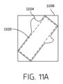
動作302において、プロセスは、オブジェクトに関連付けられた境界ボックスを決定することを含み得る。いくつかの例では、境界ボックスは、オブジェクトの画像、オブジェクトに関連付けられたライダーデータなどに基づいて決定され得る。いくつかの例では、動作302で決定された境界ボックスは、動作304で決定された境界輪郭に基づいて軸整列された境界ボックスであり得る。軸整列境界ボックスの追加の例は、本開示だけでなく、図11A~11Cでも説明される。
At act 302, the process may include determining a bounding box associated with the object. In some examples, the bounding box may be determined based on an image of the object, lidar data associated with the object, etc. In some examples, the bounding box determined in act 302 may be an axis-aligned bounding box based on the bounding contour determined in
動作304において、プロセスは、オブジェクトに関連付けられた境界輪郭を決定し得る。例えば、本明細書で説明されるシステムおよび方法は、オブジェクトに関連付けられた境界輪郭を決定するために使用され得る。境界輪郭を決定する追加の例は、図6、図7、図8A、および図8B、ならびに本開示を通して説明される。
At
動作306において、プロセスは、境界ボックスに基づいて、オブジェクトとの衝突の可能性があるかどうかを決定し得る。いくつかの例では、動作306は、プロセス300を実行するオブジェクトと車両との間の衝突の可能性を決定し得る。動作306が、境界ボックスに基づいて衝突の可能性がない(または可能性が閾値未満である)と判断する場合、プロセスは、動作314で終了し、これは、「衝突の可能性がない」状態を示す。いくつかの例では、「衝突の可能性がない」状態は、車両、他の車両、他のシステム、オブジェクトなどの1つまたは複数のシステムに通信され得る。
At act 306, the process may determine whether there is a potential collision with the object based on the bounding box. In some examples, operation 306 may determine the likelihood of a collision between the
動作306が、境界ボックスに基づいて衝突の可能性(例えば、可能性が閾値を上回る)があると判定する場合、プロセスは、動作308に進む。動作308において、プロセスは、境界輪郭に基づいて、オブジェクトとの衝突の可能性があるかどうかを決定し得る。いくつかの例では、動作308は、プロセス300を実行するオブジェクトと車両との間の衝突の可能性を決定し得る。動作308が、境界輪郭に基づいて衝突の可能性がない(または可能性が閾値未満である)と判断する場合、プロセスは、動作314で終了し、これは、「衝突の可能性がない」状態を示す。
If act 306 determines that there is a likelihood of a collision based on the bounding box (eg, the likelihood is greater than a threshold), the process continues to act 308. At act 308, the process may determine whether there is a potential collision with the object based on the boundary contour. In some examples, operation 308 may determine the likelihood of a collision between the
動作308が、境界輪郭に基づいて衝突の可能性(例えば、可能性が閾値を上回る)があると判定する場合、プロセスは、動作310に進む。 If act 308 determines that there is a likelihood of a collision based on the boundary contour (eg, the likelihood is greater than a threshold), the process continues to act 310.
いくつかの例では、動作302および306で説明される境界ボックスは、ボックス/キューブ形状または他の比較的単純な幾何学的形状を有し得る。潜在的な衝突が(動作306において)検出された場合、オブジェクトのより正確な表現(例えば、境界輪郭)は、動作306において検出された潜在的な衝突を検証または反証するために使用され得る。このアプローチは、単純な計算である境界ボックスとの衝突を最初に確認することによって、コンピューティングリソースの使用を減らし得る。境界輪郭に関連付けられたより複雑な計算は、境界ボックスとの衝突が検出されない限り、または境界ボックスが軌道(および/または軌道に沿った車両のシミュレートされた位置)の閾値距離内にあると予測されない限り、実行されない場合がある。 In some examples, the bounding boxes described in acts 302 and 306 may have box/cube shapes or other relatively simple geometric shapes. If a potential collision is detected (at act 306), a more accurate representation of the object (eg, a boundary contour) may be used to verify or disprove the detected potential collision at act 306. This approach may reduce the use of computing resources by first checking for collisions with bounding boxes, which is a simple calculation. More complex calculations associated with bounding contours predict that unless a collision with the bounding box is detected or that the bounding box is within a threshold distance of the trajectory (and/or the vehicle's simulated position along the trajectory) It may not be executed unless it is done.
動作310において、プロセスは、オブジェクトとの衝突を回避するために車両アクションを決定し得る。例えば、車両アクションは、ステアリング、ブレーキ、ホーンを鳴らすこと、車両乗員に警告することなどを含み得る。本明細書で説明するように、動作310で決定される車両アクションは、オブジェクトからの距離およびオブジェクトのタイプに関連付けられる潜在的なリスクに応じて変化し得る。動作312において、動作310で決定された車両アクションは、オブジェクトとの衝突を回避するために開始される。 At act 310, the process may determine vehicle actions to avoid a collision with an object. For example, vehicle actions may include steering, braking, honking the horn, warning vehicle occupants, and the like. As described herein, the vehicle action determined in operation 310 may vary depending on the distance from the object and the potential risk associated with the type of object. In act 312, the vehicle actions determined in act 310 are initiated to avoid collision with the object.
図4Aおよび4Bは、本開示の例による、オブジェクトに関連付けられた例示的なライダー点群402およびライダー点群を画定する境界形状410を示す図である。いくつかの例では、図4Aに示されるライダー点群402は、車両に関連付けられたライダーセンサによってキャプチャされ得る。本明細書で説明されるように、ライダー点群402は、オブジェクトに関連付けられた境界輪郭を作成するために使用され得る。図4Aは、ライダー点群402内の点の一部またはすべてに関連付けられ得る境界ボックス404を示す。いくつかの例では、境界ボックス404は、車両の一般的な形状を表し得るが、一般的な形状を超えて拡張する車両の部分(例えば、車両の本体から外向きに拡張するミラーおよび他のアイテム)を含まない場合もある。
4A and 4B are diagrams illustrating an example
図4Bは、図4Aに示されるライダー点群402に基づいて生成され得る境界形状410を示す。図4Bに示されるように、境界形状410の一部は、図4Aに示される境界ボックス404の外側に拡張する。したがって、ライダー点群に関連付けられた境界形状410は、境界ボックス404よりも車両の実際の形状のより良い表現であり得る。車両がオブジェクトと衝突するかどうかを決定するとき、オブジェクトの正確な形状は、衝突の可能性を識別するために重要であり得る。本明細書で記載されるシステムおよび方法は、オブジェクトの周囲を画定する境界輪郭の作成について説明する。いくつかの例では、各境界輪郭は、オブジェクトの周囲を密接に識別するポリゴンであり得る。
FIG. 4B shows a
いくつかの例では、境界ボックス404のサイズは、オブジェクトに関連付けられたすべてのライダー点をキャプチャする可能性を向上させるために拡張され得る。図4Aに示されるように、ライダー点群402の一部は、境界ボックス404の外側に拡張する。境界ボックス404のサイズを拡張することによって、境界ボックス404の外側に位置するライダー点の一部またはすべては、境界形状410でキャプチャされ得る。したがって、オブジェクト情報を境界ボックス404内に含まれるライダー点に限定するのではなく、オブジェクトに関連付けられた境界形状410は、境界ボックス404の外側に位置するライダー点を含むことによって、オブジェクトのより良い表現を提供し得る。
In some examples, the size of
いくつかの例では、境界ボックスは、オブジェクトのサイズ、オブジェクトタイプなどに基づいて、閾値量によって拡張することができる。いくつかの例では、境界ボックス404は、サイズが0.4メートル拡張され得る。いくつかの実装形態では、この拡張は、境界形状410が、車両側面ミラー、歩行者腕などの境界ボックス404を超えて突出するオブジェクトの部分を含むことを可能にする。他の例では、境界ボックス404は、遭遇するオブジェクトの種類、安全要件、所望の安全マージンなどに基づいて任意の量だけサイズを拡張することができる。1つまたは複数の例では、境界ボックス404は、境界ボックス404のいずれかの側面の外側に位置するライダー点をキャプチャするために、4つの側面すべてに拡張される。
In some examples, the bounding box may be expanded by a threshold amount based on the size of the object, object type, etc. In some examples, bounding
図5は、本開示の例による、ライダー点群に関連付けられる凸包を生成し、凸包に基づいて境界輪郭を作成するための例示的なプロセス500を示すフローチャートである。プロセス500に関して本明細書で記載される動作は、本明細書で説明されるように、1つまたは複数の車両コンピューティングデバイスによって実行され得る。
FIG. 5 is a flowchart illustrating an
例として、プロセス500は、論理フローグラフとして示され、その各動作は、ハードウェア、ソフトウェア、またはそれらの組み合わせで実装することができる一連の動作を表す。ソフトウェアの場合において、動作は、1つまたは複数のプロセッサによって実行された場合に、列挙した動作を実行する1つまたは複数のコンピュータ可読記憶媒体に格納されたコンピュータ実行可能命令を表すことができる。一般に、コンピュータ実行可能命令は、特定の機能を実行するか、または特定の抽象データタイプを実装するルーティン、プログラム、オブジェクト、コンポーネント、データ構造などを含み得る。動作が記載される順序は、限定として解釈されることを意図するものではなく、プロセス500を実装するために、記載される動作の任意の数を任意の順序でおよび/または並行して結合(または省略)することができる。いくつかの例では、多様な分岐は、個別に、または本明細書で説明される他の動作と組み合わせて使用され得る代替の実装を表す。
As an example,
動作502において、プロセスは、車両に近接する環境に関連付けられたライダーデータを受信することを含み得る。いくつかの例では、ライダーデータは、車両ナビゲーションまたは衝突回避システムにとって重要であり得る1つまたは複数のオブジェクトを含み得る。 At operation 502, the process may include receiving lidar data associated with the environment proximate the vehicle. In some examples, lidar data may include one or more objects that may be important to vehicle navigation or collision avoidance systems.
動作504において、プロセスは、ライダーデータ内で識別されたオブジェクトに関連付けられた点群を決定し得る。例えば、オブジェクトは、車両の計画された経路内にあってもよく、または車両の計画された経路の近くにあってもよい。いくつかの例では、オブジェクトに関連付けられた点群は、動作502で受信されたライダーデータの一部であり得る。 At act 504, the process may determine a point cloud associated with the object identified within the lidar data. For example, the object may be within or near the vehicle's planned path. In some examples, the point cloud associated with the object may be part of the lidar data received in operation 502.
動作506において、プロセスは、オブジェクトに関連付けられた点群を2次元平面上に投影し得る。動作508において、プロセスは、点群に関連付けられた凸包を生成し得る。いくつかの例では、凸包は、点群に関連付けられた複数の境界縁を含み得る。1つまたは複数の例では、凸包は、有限の一組の点について凸包を計算するための既知のアルゴリズムを使用して生成され得る。いくつかの例では、凸包は、5つ以上の境界縁を有し得る。
At act 506, the process may project the point cloud associated with the object onto a two-dimensional plane. At
いくつかの例では、点群または点の他のグループ化に関連付けられた点は、所定のグリッド上の最も近い位置に再配置され得る。例えば、所定のグリッドは、グリッド点間の1センチメートルなどの均一な間隔を有し得る。この点群の各点は、最も近いグリッド点に再配置することができる。いくつかの例では、2つ以上の点が同じグリッド点に配置され得る。この状況では、同じグリッド点のすべての重複点が削除され、それにより、グリッド点に1つの点が残る。 In some examples, points associated with a point cloud or other grouping of points may be relocated to the closest position on a predetermined grid. For example, a given grid may have uniform spacing, such as one centimeter between grid points. Each point in this point cloud can be relocated to the nearest grid point. In some examples, two or more points may be placed on the same grid point. In this situation, all duplicate points of the same grid point are removed, thereby leaving one point at the grid point.
いくつかの例では、点群内の点を所定のグリッドに整列させることは、グリッド内に表現される点がより少ない場合があるため、点群に関連付けられた境界輪郭の作成を単純化し得る。この単純化は、点群から境界輪郭を生成するために必要な時間およびコンピューティングリソースを削減し得る。 In some instances, aligning the points in a point cloud to a predetermined grid may simplify the creation of boundary contours associated with the point cloud, since fewer points may be represented in the grid. . This simplification may reduce the time and computing resources required to generate boundary contours from point clouds.
動作510において、プロセスは、凸包に関連付けられたもっとも長い境界縁を決定し得る。最長境界縁は、第1のエンドポイントおよび第2のエンドポイントを有することができる。 At act 510, the process may determine the longest bounding edge associated with the convex hull. The longest bounding edge can have a first endpoint and a second endpoint.
動作512において、プロセスは、最長境界縁を2つのより短い境界縁に置き換え得る。いくつかの例では、第1の短い境界縁は、第1のエンドポイントを含み得、第2の短い境界縁は、第2のエンドポイントを含み得る。いくつかの実装形態では、最長境界縁を置き換えることは、凸包の内部の内部点(例えば、内部ライダー点)を決定することを含み得る。第1の短い境界縁は、第1のエンドポイントおよび内部点に基づいてもよい。第2の短い境界縁は、内部点および第2のエンドポイントに基づいてもよい。いくつかの例では、動作512は、2つのより短い境界縁によって形成される角度に少なくとも部分的に基づくことができる。動作512の追加の例は、図6および図7に関連して、ならびに本開示全体を通して提供される。
In
動作514において、プロセスは、次の最長境界縁が除去するには短すぎるかどうかを決定し得る。いくつかの例では、次の最長境界縁の長さが動作512で置き換えられた第1の境界縁の長さの半分未満である場合、次の最長境界縁を除去するには短すぎる場合がある。代替の例では、他のパラメータを使用して、次の最長境界縁が短すぎて除去できない時期を決定し得る。例えば、他のパラメータは、第1の閾値を満たすか、または超える凸包の境界縁の数、第2の閾値未満である最の長く残る境界縁の長さ、または更新された凸包に関連付けられた内部点の数が第3の閾値未満であることを含み得る。
At act 514, the process may determine whether the next longest border edge is too short to remove. In some examples, the next longest border edge may be too short to remove if the length of the next longest border edge is less than half the length of the first border edge replaced in
次の最長境界縁が除去するには短すぎない場合、プロセスは、次の最長境界縁を置き換えるために動作512に戻る。
If the next longest border edge is not too short to remove, the process returns to
次の最長境界縁が除去するには短すぎる場合、プロセスは、動作516に進み、ここでプロセスは、オブジェクトに関連付けられた境界輪郭を作成し得る。いくつかの例では、境界輪郭は、点群に関連付けられた凸包の境界縁に基づいている。いくつかの例では、オブジェクトに関連付けられた境界輪郭を使用して、車両とオブジェクトとの間の衝突の可能性を決定することができる。
If the next longest boundary edge is too short to remove, the process proceeds to
いくつかの例では、各点は、1つまた複数の三角形のベクトルである。一連の点内のすべての点を包含する複数の三角形を作成した後、様々な縁を除去して、一連の点に関連付けられた外側境界を画定し得る。しかしながら、この技術は、外側の境界を画定しようとして、一連の点内のすべての点を包含する三角形の生成および処理を必要とするため、時間がかかる場合がある。本明細書で説明するシステムおよび方法は、境界輪郭を生成するためにより少ないコンピューティングリソースを使用するより速い技術を提供し得る。 In some examples, each point is a vector of one or more triangles. After creating a plurality of triangles that encompass all points in the series of points, various edges may be removed to define the outer boundary associated with the series of points. However, this technique can be time consuming because it requires the generation and processing of triangles encompassing all points in the set of points in an attempt to define the outer boundary. The systems and methods described herein may provide faster techniques that use fewer computing resources to generate boundary contours.
図6は、本開示の例による、凸包の境界縁を2つのより短いセグメントに置き換えるための例示的なプロセス600を示す図である。図6に示されるように、ポリゴン620は、任意の数の境界縁および境界縁内に含まれる任意の数の点(例えば、ライダー点)を含み得る。図6の例では、ポリゴン620は、複数の点を含む。これらの点のいくつかは、602-1、602-2,602-3および602-4としてラベル付けされている。いくつかの例では、点602は、ポリゴン(例えば、点602-1、602-3、および602-4)の内側に、またはポリゴンの境界(例えば、点602-2)上に位置し得る。ポリゴン620の例示的な境界縁604が図6に示されている。
FIG. 6 is a diagram illustrating an
いくつかの実施形態では、ポリゴンに関連付けられたすべての点は、ポリゴンの境界上、またはポリゴン内側にあることができる。本明細書で説明されるように、ポリゴンの1つまたは複数の境界縁は、より厳密な境界輪郭を作成するために置き換えられ得る。1つまたは複数の例では、結果として生じるポリゴン(境界縁を置き換えた後)は、単純なポリゴン形状を維持することができる。例えば、結果として生じるポリゴンは、任意のループ、穴、または自己交差縁を有さなくてもよい。本明細書で記載される例は、単純なポリゴン形状を維持する方法での境界縁の除去を例示する。 In some embodiments, all points associated with a polygon can be on the boundary of the polygon or inside the polygon. As described herein, one or more bounding edges of a polygon may be replaced to create a tighter bounding contour. In one or more examples, the resulting polygon (after replacing the bounding edges) may maintain a simple polygon shape. For example, the resulting polygon may not have any loops, holes, or self-intersecting edges. The examples described herein illustrate the removal of bounding edges in a way that maintains a simple polygon shape.
図6に示されるように、ポリゴン630は、上述のポリゴン320に類似している。ポリゴン630に基づいて、本明細書に記載のシステムおよび方法は、2つのより短い境界縁に置き換えるために最長境界縁を選択する。一例では、最長境界縁は、第1のエンドポイント602-5および第2のエンドポイント602-6を有する境界縁606であり得る。エンドポイント602-5および602-6は、ポリゴン630の境界に関連付けられた点である。
As shown in FIG. 6,
いくつかの例では、より短い境界縁の複数のペアーは、最長境界縁606を置き換えるための可能な候補として識別され得る。ポリゴン630に示されるように、第1のペアーのより短い境界縁は、境界縁608および610として示される。例えば、第1の短い境界縁608は、点602-5(最長境界縁606のエンドポイントの1つ)から点602-3(ポリゴン620に示される)まで拡張する。この例では、点602-3は、ポリゴン内側の内部点である。ポリゴン630に示されるように、第2の短い境界縁610は、点602-6(最長境界縁606の別のエンドポイント)から点602-3 (ポリゴン620に示される)まで拡張する。したがって、第1のペアーのより短い境界縁608、610は、点602-3と接続することによって最長境界縁606を置き換える。
In some examples, pairs of shorter border edges may be identified as possible candidates to replace the
図6の例では、第2のペアーのより短い境界縁が境界縁612および614として示される。例えば、第1の短い境界縁612は、点602-5(最長境界縁606のエンドポイントの1つ)から点602-4(ポリゴン620に示される)まで拡張する。この例では、点602-4は、ポリゴン内側の内部点である。ポリゴン630に示されるように、第2の短い境界縁614は、点602-6(最長境界縁606の別のエンドポイント)から点602-4(ポリゴン620に示される)まで拡張する。この状況では、第2のペアーのより短い境界縁612、614は、点602-4と接続することによって最長境界縁606を置き換える。
In the example of FIG. 6, the second pair of shorter border edges are shown as border edges 612 and 614. For example, the first
したがって、最長境界縁606を置き換える2つの候補は、第1のペアー608、610および第2のペアー612、614である。いくつかの例では、特定の候補を選択するために、記載されたシステムおよび方法は、各ペアーに関連付けられた2つのより短い境界縁の間の角度を識別し得る。1つまたは複数の例では、選択されたペアーのより短い境界縁は、2つのより短い境界縁の間で最大の角度を有するペアーである。図6の例では、第1のペアーのより短い境界縁608、610は、616の角度を有する。図6に示されるように、第2のペアーのより短い境界縁612、614は、618の角度を有する。この例では、角度616は、角度618よりも大きい。したがって、第1のペアーのより短い境界縁608、610が選択され、最長境界縁606を置き換える。
Therefore, the two candidates to replace the
図6に示されるように、ポリゴン640は、上述したポリゴン620および630に類似している。ポリゴン640を参照すると、最長境界縁606は、2つのより短い境界縁608および610に置き換えられている。ポリゴン640に示されるように、新しいポリゴンは、最長境界縁606の置き換えに基づいてより小さい。より短い境界縁608および610は、以前はポリゴン内に位置していた点602-3を共有するため、ポリゴンの完全性は、凸包を締め付けながら維持される。いくつかの例では、より短い境界縁608および610は、任意の点を除去することなく、最長境界縁606を置き換える。
As shown in FIG. 6,
いくつかの例では、記載されたシステムおよび方法は、図6に関して説明されたプロセス600を繰り返して、最長の境界縁を除去し続ける。図5に関して上述したように、プロセスは、次の最長境界縁が短すぎるまで繰り返され得る。
In some examples, the described systems and methods repeat the
図7は、本開示の例による、凸包の境界縁を2つのより短いセグメントに置き換えるための別の例示的なプロセス700を示す図である。図7に示されるように、ポリゴン710は、図6に関して説明されたポリゴンと類似である。ポリゴン710は、上述したように、新しい境界縁608および610を有するポリゴンを示す。いくつかの例では、境界縁610は、置き換えるべき次の最長境界縁であると決定される。図7のポリゴン710に示されるように、より短い境界縁704および706のペアーは、現在の最長境界縁610を置き換えるための候補として識別される。この例では、より短い境界縁704および706に関連付けられた角度は、他のより短い境界縁候補に関連付けられた角度と同じである。いくつかの例では、2つの角度が同じ場合、記載されたシステムおよび方法は、候補のうちの1つをランダムに選択し得る。図7の例では、現在の最長境界縁610は、ポリゴン720に示されるように、新しいより短い境界縁706および708に置き換えられる。例示的なポリゴン720において、新しい短い境界縁706は、702-3および702-4のエンドポイントを有し、新しい短い境界縁708は、702-4および602-6のエンドポイントを有する。
FIG. 7 is a diagram illustrating another
図8Aおよび8Bは、本開示の例による、境界縁上のライダー点およびライダー点の大部分から離れて配置された例示的な迷走点を有する例示的な凸包を示す図である。図8Aの例では、凸包は、凸包の境界上に複数のライダー点を有する凸包が示されている。例えば、点802-1、802-2、および802-3は、凸包境界上に位置する。図8Aに示されるように、提案された新しい境界縁804は、点802-1から802-3まで拡張する。いくつかの例では、この提案された新しい境界縁804は、新しい縁804が境界から点802-2を除去することになるため、許可されない。この状況では、点802-2は凸包の外側にある。1つまたは複数の例では、すべての点が凸包内にあることが必要とされ得るか、または凸包の境界に関連付けられ得るため、このタイプの境界縁の置き換えは、許可されない。
8A and 8B are diagrams illustrating an example convex hull with lidar points on the boundary edge and example stray points located away from a majority of the lidar points, according to examples of the present disclosure. In the example of FIG. 8A, the convex hull is shown as having a plurality of lidar points on the boundary of the convex hull. For example, points 802-1, 802-2, and 802-3 are located on the convex hull boundary. As shown in FIG. 8A, the proposed
図8Bの例では、例示的な迷走点810は、ライダー点の大部分から離れて配置される。いくつかの例では、点810は、凸包ポリゴンの一部として維持される。1つまたは複数の例では、点810は、ポリゴンから取り除かれず、点810をポリゴンの外側に位置させる縁は置き換えられない(図8Aに関して説明されるように)。
In the example of FIG. 8B, the exemplary
いくつかの例では、境界縁は、各境界縁の置換後に単純なポリゴンが維持されることを確実にするために、順次置換される。特定の例では、本明細書に記載のシステムおよび方法は、静的オブジェクトまたは動的オブジェクトを表す凸包と共に使用され得る。 In some examples, border edges are replaced sequentially to ensure that simple polygons are maintained after each border edge replacement. In particular examples, the systems and methods described herein may be used with convex hulls representing static or dynamic objects.
図9は、本開示の例による、オブジェクトの境界輪郭に基づいて車両とオブジェクトとの間の距離を決定するための例示的なプロセス900を示すフローチャートである。プロセス900に関して本明細書で記載される動作は、本明細書で説明されるように、1つまたは複数の車両コンピューティングデバイスによって実行され得る。
FIG. 9 is a flowchart illustrating an
例として、プロセス900は、論理フローグラフとして示され、その各動作は、ハードウェア、ソフトウェア、またはそれらの組み合わせで実装することができる一連の動作を表す。ソフトウェアの場合において、動作は、1つまたは複数のプロセッサによって実行された場合に、列挙した動作を実行する1つまたは複数のコンピュータ可読記憶媒体に格納されたコンピュータ実行可能命令を表すことができる。一般に、コンピュータ実行可能命令は、特定の機能を実行するか、または特定の抽象データタイプを実装するルーティン、プログラム、オブジェクト、コンポーネント、データ構造などを含み得る。動作が記載される順序は、限定として解釈されることを意図するものではなく、プロセス900を実装するために、記載される動作の任意の数を任意の順序でおよび/または並行して結合(または省略)することができる。いくつかの例では、多様な分岐は、個別に、または本明細書で説明される他の動作と組み合わせて使用され得る代替の実装を表す。
As an example,
動作902において、プロセスは、車両に関連付けられた軌道を受信することを含み得る。軌道は、車両が目的地に向かって追跡するための計画された経路であり得る。動作904において、プロセスは、車両に関連付けられたセンサからセンサデータを受信し得る。いくつかの例では、センサは、ライダーセンサであり得、センサデータは、ライダー点群を含むことができるライダーデータであり得る。
At operation 902, the process may include receiving a trajectory associated with a vehicle. A trajectory may be a planned route for a vehicle to follow toward a destination. At
動作906において、プロセスは、センサデータに表されるオブジェクトに関連付けられた境界輪郭を決定し得る。いくつかの例では、境界輪郭は、オブジェクトに関連付けられたライダー点群に基づいて決定され得る。
At
動作908において、プロセスは、車両に関連付けられた軌道に基づいて車両のシミュレートされた位置を決定し得る。いくつかの例では、車両の位置は、軌道に沿った異なる点でシミュレートされて、それらの異なる点での障害物との衝突の可能性を決定し得る。将来の時点で軌道に沿った潜在的な衝突を識別することによって、車両は、衝突の可能性を低減または排除する1つまたは複数のアクションを取るための余分な時間を有し得る。いくつかの例では、衝突は、車両が将来の時間に占有し得るポーズから横方向に検出され得る。例えば、複数のポーズは、車両がその現在の軌道に応じて占有し得ることを予測することができる。これらのポーズのそれぞれに沿って、横方向の衝突検出技術を、開示された技術に従って適用することができる。同様の技術は、複数の投影された軌道/ポーズに適用されて、複数の経路に沿った、および/または異なる将来の決定の可能性に応答して、車両の予測される可能性のある将来のポーズを説明することができる。
At
動作910において、プロセスは、境界輪郭の予測された位置を決定し得る。いくつかの例では、軌道に沿った異なる点(例えば、将来の時間)における車両のシミュレートされた位置は、同じ将来の時間における境界輪郭の予測された位置と比較され得る。いくつかの例では、動作910は、境界輪郭に関連付けられたオブジェクトの予測された軌道を受信することを含み得、いくつかの例では、予測された位置は、予測された軌道に基づくことができる。いくつかの例では、動作910は、予測された軌道に沿った境界輪郭の予測された向きを決定することを含むことができる。
At
動作912において、プロセスは、将来の時点で車両とオブジェクトとの間の距離を決定し得る。いくつかの例では、距離は、車両のシミュレートされた位置およびオブジェクトを表す境界輪郭の予測された位置に基づいて決定され得る。車両と境界輪郭との間の距離は、車両とオブジェクトとの間の衝突の可能性を決定するのに役立ち得る。
At
動作914において、プロセスは、車両とオブジェクトとの間の距離に基づいてアクションを実行し得る。いくつかの例では、車両とオブジェクトとの間の距離が閾値未満である場合、アクションは、開始され得る。いくつかの例では、閾値は、車両および/またはオブジェクトの速度、オブジェクトの分類、環境に関連付けられたマップデータ、オブジェクトの行動などに基づいてもよい。本明細書で説明されるように、アクションは、車両とオブジェクトとの間の衝突の可能性を低減または排除する運転操作を含み得る。 At act 914, the process may perform an action based on the distance between the vehicle and the object. In some examples, an action may be initiated if the distance between the vehicle and the object is less than a threshold. In some examples, the threshold may be based on vehicle and/or object speed, object classification, map data associated with the environment, object behavior, etc. As described herein, the action may include a driving maneuver that reduces or eliminates the possibility of a collision between the vehicle and the object.
動作916において、プロセスは、軌道上の更新された車両位置を(後で)決定し得る。いくつかの例では、プロセスは、後の時間に基づいてシミュレートされた車両位置を決定し、その後の時間における衝突の可能性を決定するために動作908に戻ってもよい。
At
図10Aおよび10Bは、本開示の例による、車両と境界輪郭1004との間の距離を決定するときのオブジェクトの例示的な車両軌道1002および境界輪郭1004を示す図である。いくつかの例では、車両軌道1002は、環境を通る車両の計画されたナビゲーションパスを識別する。図10Aおよび図10Bに示されるように、境界輪郭1004は、車両軌道1002に近接して位置する。本明細書で説明されるように、境界輪郭1004は、車両、歩行者、動物、建物、道路標識、木などの任意のタイプのオブジェクトに関連付けられ得る。
10A and 10B are diagrams illustrating an
図10Bは、車両1006が車両軌道1002上の特定の位置に位置する特定の時間を示す。図10Bの例では、車両1006と境界輪郭1004によって画定されたオブジェクトとの間の距離を決定することが望ましい場合がある。この距離は、車両軌道1002に従うときに、車両1006が境界輪郭1004を過ぎて安全に案内できるかどうかを決定するために重要であり得る。いくつかの実施形態では、車両1006と境界輪郭1004によって画定されるオブジェクトとの間の距離は、レイトレース1008によって示されるように、レイキャスティングによって決定され得る。
FIG. 10B shows a particular time when
車両1006と境界輪郭1004との間の距離に基づいて、車両1006は、境界輪郭1004に関連付けられたオブジェクトとの衝突を回避するために1つまたは複数のアクションを取る場合がある。例えば、車両1006は、オブジェクトからの距離およびオブジェクトのタイプに関連付けられる潜在的なリスクに応じて、ステアリング、ブレーキ、ホーンの鳴り、車両乗員の警告などのアクションを取る場合がある。いくつかの例では、高速移動車両などの特定のタイプのオブジェクトは、木または交通標識などの静止したオブジェクトよりも車両1006と衝突するリスクが高い可能性がある。
Based on the distance between
いくつかの例では、車両1006および境界輪郭1004は、車両1006が車両軌道1002に沿って移動するにつれて、車両1006とオブジェクトとの間の将来の衝突を決定するために、車両の軌道に沿って伝搬され得る。いくつかの実装形態では、境界輪郭1004は、車両軌道1002に沿った複数の点で決定され得る。車両1006の位置は、本明細書で説明されるように、レイキャスティングを使用して、車両軌道1002に沿ったそれらの同じ点で決定され得る。車両軌道1002に沿ったこれらの点は、空間および時間における特定の点であり得る。
In some examples,
いくつかの例では、本明細書に記載のシステムおよび方法は、車両1006が境界輪郭1004に関連付けられたオブジェクトを安全に通り過ぎて案内できるかどうかを決定し得る。衝突がない場合でも、いくつかの例では、オブジェクトを通過する車両1006の安全なナビゲーションを確実にするための最小距離の閾値(例えば、安全マージン)があり得る。
In some examples, the systems and methods described herein may determine whether
いくつかの例では、第1の境界を使用して、車両と外部オブジェクトとの間の潜在的な衝突を検出することができる。例えば、第1の境界は、境界ボックス/キューブまたは他の比較的単純な幾何学的形状に関連付けることができる。潜在的な衝突が検出された場合、開示された技術など、より正確な(および場合によってはより多くのプロセッサ集約的な)境界技術を使用することができる。次に、より正確な境界技術を使用して、境界ボックス(または他の形状)を使用して検出された潜在的な衝突を検証または反証することができる。 In some examples, the first boundary may be used to detect a potential collision between the vehicle and an external object. For example, the first boundary may be associated with a bounding box/cube or other relatively simple geometric shape. If a potential collision is detected, a more accurate (and possibly more processor intensive) boundary technique, such as the disclosed technique, can be used. More accurate bounding techniques can then be used to verify or disprove potential collisions detected using bounding boxes (or other shapes).
図10Bに示されるように、レイトレース1008は、車両1006の側面から垂直に拡張し、境界輪郭1004を通過し得る。いくつかの例では、車両1006と境界輪郭1004に関連付けられたオブジェクトとの間に衝突が発生し得るかどうかを決定するとき、本明細書で説明されるシステムおよび方法は、レイトレース1008によって境界輪郭1004内で交差する境界の数を決定する。特定の例では、レイトレース1008が境界輪郭1004を通過するときに偶数の境界を交差する場合、車両1006とオブジェクトとの間に衝突はない。図10Bの例では、レイトレース1008は、境界輪郭1004の2つの境界を交差する(例えば、光線が境界輪郭1004に入るときに1回、および光線が境界輪郭1004から出るときに1回)。境界の数が偶数であるため、車両1006は、オブジェクトと衝突する可能性が低い。これは、車両1006と境界輪郭1004との間の分離を示す図10Bによって確認され得る。いくつかの例では、レイトレース1008が奇数の境界を交差する場合、それは、レイトレース1008が境界輪郭1004内で発生したことを意味する。レイトレース1008が境界輪郭1004内に発生する場合、それは、衝突の兆候である(例えば、車両1006の少なくとも一部とオブジェクトが同時に同じ空間を共有する)。
As shown in FIG. 10B,
図10Bの例では、レイトレース1008は、車両1006の側面から垂直に延びるように示されている。他の例では、レイトレース1008は、車両1006の任意の部分から任意の方向に拡張し得る。例えば、レイトレース1008は、車両1006の前方または後方から長手方向に延びて、車両1006と車両1006の前方または後方のオブジェクトとの間の距離を決定し得る。
In the example of FIG. 10B,
図11A~11Cは、本開示の例による、例示的な境界ボックス、境界輪郭、および軸整列された境界ボックスを示す図である。図11Aの例では、オブジェクトの3つの表現、すなわち境界ボックス1102、境界輪郭1104、および軸整列境界ボックス(AABB)1106が示されている。図11Aに表される例示的なオブジェクトは、車両であり得る。いくつかの例では、境界ボックス1102は、オブジェクト(すなわち、車両)の重要な部分を表す長方形である。図11Aに示されるように、境界ボックス1102の長い側面は、車両の側面を表し得る。しかしながら、境界ボックス1102の長い側面は、車両の各側面から延びるサイドミラーを含まない場合がある。したがって、境界ボックス1102は、車両または他のオブジェクトのすべての部分を正確に表さない場合がある。
11A-11C are diagrams illustrating example bounding boxes, bounding contours, and axis-aligned bounding boxes, according to examples of the present disclosure. In the example of FIG. 11A, three representations of the object are shown: a
図11Aの例では、境界輪郭1104は、車両のより正確な表現を提供し得る。例えば、境界輪郭1104は、車両と別のオブジェクトとの間の衝突の可能性を決定するときに考慮することが重要であり得る、車両の2つのサイドミラーを識別する。上記のように、車両のサイドミラーは、境界ボックス1102内に表されておらず、これは、本明細書で記載されるシステムおよび方法が、境界ボックス1102のみに基づくサイドミラーを認識していないため、衝突の可能性を増加させる場合がある。
In the example of FIG. 11A,
図11Aはまた、軸整列境界グボックス(AABB)1106を含む。AABB(1106)は、x-y軸、車両または他のオブジェクトの長手方向軸などの特定の軸と整列され得る境界ボックスである。図11Aの例では、AABB(1106)は、x-y軸上に整列される。いくつかの例では、AABB(1106)は、AABB(1106)によって表される車両と別のオブジェクトとの間の衝突の可能性に関する早期確認を実行するために使用される。例えば、AABB(1106)を使用する早期確認は、動的輪郭のために動的AABBツリーを使用し得る。動的AABBツリーは、クエリ輪郭のAABBと重複するAABBsを有する輪郭の効率的な検索を可能にし得る(例えば、他のオブジェクトとの衝突の可能性を確認する車両の輪郭)。 FIG. 11A also includes an axis alignment bounding box (AABB) 1106. AABB (1106) is a bounding box that can be aligned with a particular axis, such as the xy axis, the longitudinal axis of a vehicle or other object. In the example of FIG. 11A, AABB (1106) is aligned on the xy axis. In some examples, AABB (1106) is used to perform an early check regarding a potential collision between the vehicle represented by AABB (1106) and another object. For example, early validation using AABB (1106) may use a dynamic AABB tree for dynamic contours. A dynamic AABB tree may enable efficient searching for contours with AABBs that overlap with the AABB of the query contour (e.g., a vehicle contour to check for possible collisions with other objects).
図11Bの例では、環境1110は、第1の車両(またはオブジェクト)1114および第2の車両(またはオブジェクト)1118を含む。この例では、第1の車両1114は、関連付けられたAABB(1112)を有し、第2の車両1118は、関連付けられたAABB(1116)を有する。図11Bに示されるように、AABB(1112)およびAABB(1116)は、ローカルユニバーサル横メルカトル(UTM)と整列される。したがって、AABB(1112)およびAABB(1116)は、図11Bに示される水平軸および垂直軸と整列される。図11Bの例では、AABB(1112)およびAABB(1116)は、互いに重複しており、これは、第1の車両1114と第2の車両1118との間の潜在的な衝突を検出するための衝突回避システムまたはアルゴリズムを引き起こし得る。しかしながら、図11Bに示す例は、衝突状況を表すものではない。代わりに、図11Bの例では、第1の車両1114と第2の車両1118との間に適切な間隔がある。2つの車両1114および1118間の潜在的な衝突は、それぞれ第1の車両1114および第2の車両1118を正確に表さないAABB(1112)およびAABB(1116)の領域に起因して示され得る。
In the example of FIG. 11B,
図11Cの例では、環境1120は、第1の車両(またはオブジェクト)1124および第2の車両(またはオブジェクト)1128を含む。この例では、第1の車両1124は、関連付けられたAABB(1122)を有し、第2の車両1128は、関連付けられたAABB(1126)を有する。図11Cに示されるように、AABB(1122)およびAABB(1126)は、車両1124および1128のヨーと整列される。車両1124および1128のヨーとのこの整列は、AABB(1122)および1126の重複を回避する。A ABBs(1122)および1126を車両のヨーに整列されることによって、AABB(1122)および1126は、車両の輪郭のより正確な表現を提供する。これらの「より密接な」AABBs(1122)および1126は、重複せず、これは、環境1120のより正確な表現である。図11Cの例では、衝突回避システムまたはアルゴリズムは、第1の車両1124と第2の車両1128との間の潜在的な衝突を検出しない場合がある。
In the example of FIG. 11C,
いくつかの例では、車両のプランニングおよび/または予測コンポーネントは、1つまたは複数の境界ボックス、境界輪郭、およびAABBsを使用して、車両軌道を決定し、車両軌道に沿って車両を案内し、車両と他のオブジェクトとの間の潜在的な衝突を予測し、潜在的な衝突に基づいてアクション(例えば、車両アクション)を開始し得る。1つまたは複数の例では、本明細書に記載のシステムおよび方法は、最初に、衝突を予測するか、またはオブジェクトが車両からの閾値距離を維持するかどうかを決定するために粗い解析を実行し得る。この閾値距離は、車両に関連付けられた安全半径とも称され得る。この粗い解析は、例えば、AABBまたは境界ボックスを使用して実施してもよい。この粗い解析は、最小限のコンピューティングリソースで迅速に実行できる。粗い解析が潜在的な衝突を識別する場合、または車両とオブジェクトが互いに閾値距離を維持できない場合、記載されたシステムおよび方法は、例えば、境界輪郭およびレイトレーシングを使用して、より詳細な解析を実行し得る。いくつかの例では、車両プランニングは、前車両の車軸および後車両の車軸の両方から実行され得る。 In some examples, a vehicle planning and/or prediction component uses one or more bounding boxes, bounding contours, and AABBs to determine a vehicle trajectory, guide the vehicle along the vehicle trajectory, and Potential collisions between the vehicle and other objects may be predicted and actions (e.g., vehicle actions) may be initiated based on the potential collision. In one or more examples, the systems and methods described herein first perform a coarse analysis to predict a collision or determine whether the object maintains a threshold distance from the vehicle. It is possible. This threshold distance may also be referred to as a safety radius associated with the vehicle. This coarse analysis may be performed using AABB or bounding boxes, for example. This coarse analysis can be performed quickly with minimal computing resources. If a coarse analysis identifies a potential collision, or if the vehicle and object cannot maintain a threshold distance from each other, the described system and method can perform a more detailed analysis using, for example, boundary contours and ray tracing. It can be executed. In some examples, vehicle planning may be performed from both the front vehicle axle and the rear vehicle axle.
いくつかの例では、衝突確認は、時間または距離に制限され得る。例えば、衝突確認は、次の数秒間に時間が制限され得る。動的環境では、環境内で複数の動的オブジェクトが移動するため、遠い将来の衝突チェックが不正確になる可能性がある。したがって、コンピューティングリソースを節約し、正確なデータを生成するために、衝突チェックは、数秒先の将来に制限され得る。 In some examples, collision confirmation may be limited to time or distance. For example, collision confirmation may be time limited to the next few seconds. In a dynamic environment, collision checking in the distant future can be inaccurate due to multiple dynamic objects moving within the environment. Therefore, to save computing resources and generate accurate data, collision checking may be limited to a few seconds into the future.
加えて、衝突確認は、車両からの特定の距離に限定され得る。例えば、軌道に沿って移動する車両は、車両または車両の軌道から特定の距離内にあるオブジェクトに関係し得る。いくつかの実装形態では、分析のために閾値距離内で移動するまで、車両および車両の軌道から遠く離れたオブジェクトを無視することができる。これらのオブジェクトを無視することは、コンピューティングリソースを節約し、それらのコンピューティングリソースを、車両または車両軌道へのそれらの近接に基づいて高い優先度であるオブジェクトに焦点を当てる。 Additionally, collision confirmation may be limited to a certain distance from the vehicle. For example, a vehicle moving along a trajectory may relate to objects that are within a certain distance from the vehicle or the vehicle's trajectory. In some implementations, objects far from the vehicle and the vehicle's trajectory may be ignored until they move within a threshold distance for analysis. Ignoring these objects saves computing resources and focuses those computing resources on objects that are high priority based on their proximity to the vehicle or vehicle trajectory.
いくつかの例では、本明細書に記載のシステムおよび方法は、車両軌道とオブジェクトに関連付けられた境界輪郭との間の衝突を確認し得る。1つまたは複数の例では、AABBツリーを作成することができ、すべての境界輪郭は、車両のヨーに整列される(図11Cに示すように)。車両軌道は、AABBツリーに追加され得る。いくつかの例では、AABBツリーは、衝突の候補について照会することができる。いくつかの例では、記載されたシステムおよび方法は、特定の期間に基づいてAABBツリーを照会し得る。 In some examples, the systems and methods described herein may identify collisions between a vehicle trajectory and a boundary contour associated with an object. In one or more examples, an AABB tree can be created, with all bounding contours aligned to the vehicle's yaw (as shown in FIG. 11C). Vehicle trajectories may be added to the AABB tree. In some examples, the AABB tree can be queried for collision candidates. In some examples, the systems and methods described may query the AABB tree based on a particular time period.
いくつかの例では、AABBツリーまたは他の技術を使用して、AABBまたは他の相対的なコース表現を使用して潜在的な衝突を決定することができる。境界ボックスを使用して潜在的な衝突を検出することに応答して、より正確な表現は、本明細書に開示されるように、境界輪郭を介して決定され得る。例えば、コース表現は、特定のシナリオにおける潜在的な衝突の第1の確率を示し得る。第1の確率が閾値を満たすことに応答して、潜在的な衝突の第2の決定は、より正確な表現を使用して行うことができる。第2の決定は、第2の確率が第1の確率と異なることができる同じシナリオにおける潜在的な衝突の第2の確率を決定することを含むことができる。第2の確率は、例えば、第1の確率よりも衝突の可能性が低いことを示し得る。より正確な表現の使用は、より粗い表現の使用よりも複雑であり得る。記載されている2段階のアプローチを使用すると、システムが潜在的な衝突を決定するための全体的な複雑さが少なくなる。 In some examples, AABB trees or other techniques may be used to determine potential collisions using AABB or other relative course representations. In response to detecting potential collisions using bounding boxes, a more accurate representation may be determined via bounding contours, as disclosed herein. For example, a course representation may indicate a first probability of a potential collision in a particular scenario. In response to the first probability meeting the threshold, a second determination of potential collisions can be made using a more accurate representation. The second determination may include determining a second probability of a potential collision in the same scenario, where the second probability may be different than the first probability. The second probability may, for example, indicate that a collision is less likely than the first probability. Using a more precise representation can be more complex than using a coarser representation. Using the two-step approach described reduces the overall complexity for the system to determine potential conflicts.
いくつかの例では、衝突が検出された場合、記載されたシステムおよび方法は、車両の現在の軌道を無効にするか、または車両からの衝突の時間および距離に基づいて軌道の精度を変更し得る。同様に、安全マージンが損なわれた場合、システムおよび方法は、車両の現在の軌道を無効にするか、または変更し得る。 In some examples, if a collision is detected, the described systems and methods override the vehicle's current trajectory or change the accuracy of the trajectory based on the time and distance of the collision from the vehicle. obtain. Similarly, the systems and methods may override or change the vehicle's current trajectory if the safety margin is compromised.
図12は、本明細書で記載される技術を実装するための例示的なシステム1200を示す図である。車両1202は、1つまたは複数の車両コンピューティングデバイス1204、1つまたは複数のセンサシステム1206、1つまたは複数のエミッター1208、1つまたは複数の通信接続部1210、少なくとも1つの直接接続1212、および1つまたは複数のドライブシステム1214を含み得る。
FIG. 12 is a diagram illustrating an
いくつかの例では、システム1200は、ドライバー(または乗員)がいつでも車両を制御することが期待されていない状態で、全体の旅程においてすべての安全に重要な機能を遂行することができる車両を説明する米国国道交通安全局によって発行されたレベル5の分類に従って動作するように構成された自律車両などの車両として実装することができる。このような例では、車両は、全ての駐車機能を含む出発から停止までの全ての機能を制御するように構成されることが可能であるため、無人化することが可能である。これは、例に過ぎず、本明細書で記載されるシステムおよび方法は、運転者によって常時、手動で制御される必要がある車両から、部分的にまたは完全に自律的に制御される車両までに及ぶ車両を含む、任意の地上車両、空路車両、または水路車両に組み込まれることが可能である。
In some examples, the
車両コンピューティングデバイス1204は、1つまたは複数のプロセッサ1216、および1つまたは複数のプロセッサ1216と通信可能に連結されたメモリ1218を含み得る。図示の例では、車両1202は、自律車両である。しかしながら、車両1202は、任意の他のタイプの車両であってよい。図示の例では、車両コンピューティングデバイス1204のメモリ1218は、位置特定コンポーネント1220、知覚コンポーネント1222、1つまたは複数のマップ1224、および1つまたは複数のシステムコントローラ1226を格納する。例示的な目的のためにメモリ1218に存在するように図12に示されているが、位置特定コンポーネント1220、知覚コンポーネント1222、1つまたは複数のマップ1224、および1つまたは複数のシステムコントローラ1226は、追加的に、または代替的に、車両1202にアクセス可能であり得る(例えば、遠隔に格納され得る)ことが企図される。
少なくとも1つの例示において、位置特定コンポーネント1220は、車両1202の位置および/または方向(例えば、x位置、y位置、z位置、ロール、ピッチ、またはヨーのうちの1つまたは複数)を決定するためにセンサシステム1206からのデータを受信する機能を含み得る。例えば、位置特定コンポーネント1220は、環境のマップを含むおよび/または要求/受信し得、マップ内の自律車両の位置および/または方向を継続的に決定し得る。いくつかの例では、位置特定コンポーネント1220は、SLAM(同時位置特定およびマッピング)、CLAMS(較正、位置特定およびマッピング、同時に)、相対的SLAM、バンドル調整、非線形最小2乗最適化などを利用して、画像データ、ライダーデータ、レーダーデータ、IMUデータ、GPSデータ、ホイールエンコーダーデータなどを受信し、自律車両の位置を正確に決定することができる。いくつかの例では、本明細書で記載されるように、位置特定コンポーネント1220は、車両1202の様々なコンポーネントにデータを提供して、軌道を生成するための、および/またはマップデータを生成または受信するための自律車両の初期位置を決定し得る。 In at least one illustration, location component 1220 is configured to determine the position and/or orientation (e.g., one or more of x-position, y-position, z-position, roll, pitch, or yaw) of vehicle 1202. may include the ability to receive data from sensor system 1206 . For example, location component 1220 may include and/or request/receive a map of the environment and may continually determine the autonomous vehicle's position and/or orientation within the map. In some examples, the localization component 1220 utilizes SLAM (simultaneous localization and mapping), CLAMS (calibration, localization and mapping simultaneously), relative SLAM, bundle adjustment, nonlinear least squares optimization, etc. The system can receive image data, lidar data, radar data, IMU data, GPS data, wheel encoder data, etc., and accurately determine the position of the autonomous vehicle. In some examples, location component 1220 provides data to various components of vehicle 1202 to generate a trajectory and/or to generate map data or as described herein. An initial position of the autonomous vehicle for receiving may be determined.
いくつかの例において、知覚コンポーネント1222は、オブジェクト検出、セグメンテーション、および/または分類を実行する機能を含み得る。いくつかの例では、知覚コンポーネント1222は、車両1202に近接する物体の存在および/または物体タイプ(例えば、自動車、歩行者、サイクリスト、建物、樹木、路面、縁石、歩道、不明なものなど)として物体の分類を示す処理されたセンサデータを提供する場合がある。追加的または代替的な例において、知覚コンポーネント1222は、検出された物体(例えば、追跡されるオブジェクト)に関連付けられる1つまたは複数の特性および/または物体が配置される環境を示す処理されたセンサデータを提供する場合がある。いくつかの例において、物体に関連付けられる特性は、x-位置(グローバルおよび/またはローカル位置)、y-位置(グローバルおよび/またはローカル位置)、z-位置(グローバルおよび/またはローカル位置)、方向(例えば、ロール、ピッチ、ヨー)、物体タイプ(例えば、分類)、物体の速度、物体の加速度、物体の範囲(サイズ)などを含むことができるが、これらに限定されない。環境に関連付けられた特性は、環境内の別の物体の存在、環境内の別の物体の状態、時刻、曜日、季節、気象条件、暗闇/光の表示などを含み得るが、これらに限定されない。 In some examples, perception component 1222 may include functionality to perform object detection, segmentation, and/or classification. In some examples, the perception component 1222 detects the presence and/or object type of an object proximate to the vehicle 1202 (e.g., car, pedestrian, cyclist, building, tree, road surface, curb, sidewalk, unknown object, etc.). Processed sensor data may be provided that indicates a classification of the object. In additional or alternative examples, the perception component 1222 is a processed sensor that is indicative of one or more characteristics associated with a detected object (e.g., a tracked object) and/or the environment in which the object is located. Data may be provided. In some examples, the properties associated with an object include x-position (global and/or local position), y-position (global and/or local position), z-position (global and/or local position), orientation. (e.g., roll, pitch, yaw), object type (e.g., classification), object velocity, object acceleration, object extent (size), and the like. Characteristics associated with the environment may include, but are not limited to, the presence of another object in the environment, the state of another object in the environment, time of day, day of the week, season, weather conditions, darkness/light indications, etc. .
いくつかの例では、知覚コンポーネント1222は、本明細書で説明されるように、任意の数の境界輪郭を作成および管理し得る境界輪郭コンポーネント1228を含み得る。特定の例では、境界輪郭コンポーネント1228は、1つまたは複数のオブジェクトに関連付けられた境界輪郭を識別する。
In some examples, perception component 1222 may include a
メモリ1218は、環境内を案内するために車両1202によって使用され得る1つまたは複数のマップ1224をさらに含み得る。いくつかの例では、マップは、これらに限定されることでないが、テクスチャ情報(例えば、色情報(例えば、RGB色情報、Lab色情報、HSV/HSL色情報)など)、強度情報(例えば、LIDAR情報、RADAR情報など)、空間情報(例えば、メッシュ上に投影された画像データ、個々の「サーフェル」(例えば、個々の色および/または明暗度に関連付けられるポリゴン))、反射性情報(例えば、鏡面性情報、再帰反射性情報、BRDF情報、BSSRDF情報など)を含む場合がある。ある例において、マップは、環境の3次元メッシュを含んでよい。いくつかの例において、マップの個々のタイルが環境の個別の部分を表すように、マップをタイル形式で格納でき、本明細書で説明するように、必要に応じて作業メモリにロードする場合がある。少なくとも1つの例示において、1つまたは複数のマップ1224は、少なくとも1つのマップ(例えば、画像および/またはメッシュ)を含んでよい。いくつかの例では、1つまたは複数のマップ1224は、ネットワーク1240を介してアクセス可能なリモートコンピューティングデバイス(コンピューティングデバイス1242など)に格納され得る。いくつかの例では、多様なマップ1224は、例えば、特性(例えば、物体のタイプ、時刻、曜日、その年の季節など)に基づいて格納され得る。多様なマップ1224を格納することは、類似のメモリ要件を有し得るが、マップにおけるデータがアクセスされ得る速度を増加させる。
Memory 1218 may further include one or more maps 1224 that may be used by vehicle 1202 to navigate within the environment. In some examples, the map includes, but is not limited to, texture information (e.g., color information (e.g., RGB color information, Lab color information, HSV/HSL color information), etc.), intensity information (e.g., LIDAR information, RADAR information, etc.), spatial information (e.g. image data projected onto a mesh, individual "surfels" (e.g. polygons associated with individual colors and/or intensities)), reflectivity information (e.g. , specularity information, retroreflectivity information, BRDF information, BSSRDF information, etc.). In some examples, the map may include a three-dimensional mesh of the environment. In some examples, the map may be stored in tile format, such that each tile of the map represents a separate portion of the environment, and may be loaded into working memory as needed, as described herein. be. In at least one example, one or more maps 1224 may include at least one map (eg, an image and/or a mesh). In some examples, one or more maps 1224 may be stored on a remote computing device (such as computing device 1242) that is accessible via
少なくとも1つの例示において、車両コンピューティングデバイス1204は、1つまたは複数のシステムコントローラ1226を含んでよく、これは、ステアリング、推進、制動、安全性、エミッター、通信、および車両1202の他のシステムを制御するように構成されてよい。これらのシステムコントローラ1226は、ドライブシステム1214の対応するシステムおよび/または車両1202の他のコンポーネントと通信することおよび/または制御することができる。
In at least one example,
いくつかの例では、メモリ1218は、車両1202に近接する様々な活動および状況を予測する予測コンポーネント1230を含み得る。少なくとも1つの例では、予測コンポーネント1230は、オブジェクトまたは他の車両の活動または状況との衝突の可能性を予測し得る。 In some examples, memory 1218 may include a prediction component 1230 that predicts various activities and conditions proximate vehicle 1202. In at least one example, prediction component 1230 may predict the likelihood of a collision with an object or other vehicle activity or situation.
いくつかの例では、メモリ1218は、様々な車両活動を計画し、目的地に到達するために車両軌道を計画するプランニングコンポーネント1232などを含み得る。少なくとも1つの例では、プラニングコンポーネント1232は、車両の軌道に沿った潜在的な衝突を識別し得る衝突確認コンポーネント1234を含み得る。本明細書で説明されるように、衝突確認コンポーネント1234は、境界輪郭を使用して、車両1202と車両の軌道の近くのオブジェクトに関連付けられた境界輪郭との間の距離(および衝突の可能性)を決定し得る。
In some examples, memory 1218 may include a planning component 1232 that plans various vehicle activities, plans a vehicle trajectory to reach a destination, and the like. In at least one example, planning component 1232 may include a
いくつかの例では、本明細書で説明されるコンポーネントのいくつかまたは全ての態様は、任意のモデル、アルゴリズム、および/または機械学習アルゴリズムを含み得る。例えば、いくつかの例示では、メモリ1218(および以下で説明されるメモリ1246)の内のコンポーネントは、ニューラルネットワークとして実装され得る。 In some examples, some or all aspects of the components described herein may include any models, algorithms, and/or machine learning algorithms. For example, in some illustrations, components within memory 1218 (and memory 1246, described below) may be implemented as a neural network.
本明細書で記載されるように、例示的なニューラルネットワークは、入力データを一連の接続された層に渡して出力を生成するアルゴリズムである。ニューラルネットワークにおける各レイヤはまた、別のニューラルネットワークを含んでよく、または(畳み込みか否かには関係なく)任意の数のレイヤを含んでもよい。本開示の文脈において理解されるように、ニューラルネットワークは、機械学習を利用してよく、これは、学習したパラメータに基づいて出力が生成されるようなアルゴリズムの広範囲のクラスを指してもよい。 As described herein, an exemplary neural network is an algorithm that passes input data through a series of connected layers to generate an output. Each layer in a neural network may also include another neural network, or any number of layers (convolutional or not). As understood in the context of this disclosure, neural networks may utilize machine learning, which may refer to a broad class of algorithms in which outputs are generated based on learned parameters.
ニューラルネットワークの脈絡で説明されるものの、任意のタイプの機械学習は、本開示と整合するように用いられてよい。例えば、機械学習アルゴリズムには、限定はされないが、回帰アルゴリズム(例えば、通常の最小2乗回帰(OLSR)、線形回帰、ロジスティック回帰、段階的回帰、多変量適応回帰スプライン(MARS)、局所推定散布図平滑化(LOESS))、インスタンスベースのアルゴリズム(例えば、リッジ回帰、最小絶対収縮および選択演算 子(LASSO)、弾性ネット、最小角度回帰(LARS))、決定ツリーアルゴリズム(例えば、分類および回帰ツリー(CART)、繰り返しダイコトマイザ3(ID3)、カイ2乗自 動相互作用検出(CHAID)、決定スタンプ、条件付き決定ツリー)、ベイジアルゴリズム(例えば、単純ベイズ、ガウシアン単純ベイズ、多項単純ベイズ、平均1依存エスティメータ(AODE)、ベイジアン信念ネットワーク(BNN)、ベイジアンネットワーク)、クラスタリングアルゴリズム(例えば、k平均、k中央値、期待値最大化(EM)、階層クラスタリング)、関連付けルール学習アルゴリズム(例えば、パーセプトロン、バックプロパゲーション、ホップフィールドネットワーク、放射基底関数ネットワーク(RBFN))、深層学習アルゴリズム(例えば、深層ボルツマンマシン(DBM)、深層信念ネットワーク(DBN)、畳み込みニューラルネットワーク(CNN)、積層自動エンコーダー)、次元削減技法(例えば、主成分分析(PCA)、主成分回帰(PCR)、部分最小2乗回帰(PLSR)、サモンマッピング、多次元尺度構成法(MDS)、射影追跡、線形判別分析(LDA)、混合判別分析(MDA)、2次判別分析(QDA)、フレキシブル判別分析(FDA))、アンサンブルアルゴリズム(例えば、ブースティング、ブートストラップアグリゲーション(バギング)、アダブースト、積層一般化(ブレンディング)、勾配ブースティングマシン(GBM)、勾配ブースト回帰ツリー(GBRT)、ランダムフォレスト)、SVM(サポートベクターマシン)、教師あり学習、教師なし学習、半教師あり学習などを含み得る。 Although described in the context of neural networks, any type of machine learning may be used consistent with this disclosure. For example, machine learning algorithms include, but are not limited to, regression algorithms (e.g., ordinary least squares regression (OLSR), linear regression, logistic regression, stepwise regression, multivariate adaptive regression splines (MARS), local estimation scatter figure smoothing (LOESS)), instance-based algorithms (e.g. ridge regression, least absolute shrinkage and selection operator (LASSO), elastic net, least angle regression (LARS)), decision tree algorithms (e.g. classification and regression trees (CART), Iterative Dichotomizer 3 (ID3), Chi-Square Automatic Interaction Detection (CHAID), Decision Stamp, Conditional Decision Tree), Bayesian algorithms (e.g. Naive Bayes, Gaussian Naive Bayes, Multinomial Naive Bayes, Mean 1 Dependence Estimator (AODE), Bayesian Belief Network (BNN), Bayesian Network), Clustering Algorithms (e.g. k-means, k-median, Expectation Maximization (EM), Hierarchical Clustering), Association Rule Learning Algorithms (e.g. Perceptron) , backpropagation, Hopfield network, radial basis function network (RBFN)), deep learning algorithms (e.g., deep Boltzmann machine (DBM), deep belief network (DBN), convolutional neural network (CNN), stacked autoencoder), Dimensionality reduction techniques (e.g., Principal Component Analysis (PCA), Principal Component Regression (PCR), Partial Least Squares Regression (PLSR), Summon mapping, Multidimensional Scaling (MDS), Projection Pursuit, Linear Discriminant Analysis (LDA) , mixture discriminant analysis (MDA), quadratic discriminant analysis (QDA), flexible discriminant analysis (FDA)), ensemble algorithms (e.g. boosting, bootstrap aggregation (bagging), AdaBoost, stacked generalization (blending), gradient boosting) machine (GBM), gradient-boosted regression tree (GBRT), random forest), SVM (support vector machine), supervised learning, unsupervised learning, semi-supervised learning, etc.
アーキテクチャの追加の例は、ResNet50、ResNetl0l、VGG、DenseNet、PointNetなどのニューラルネットワークを含む。 Additional examples of architectures include neural networks such as ResNet50, ResNetl01, VGG, DenseNet, PointNet, etc.
少なくとも1つの例において、センサシステム1206は、ライダーセンサ、レーダーセンサ、超音波変換器、ソナーセンサ、位置センサ(例えば、GPS、コンパスなど)、慣性センサ(例えば、慣性測定装置(IMUs)、加速度計、磁力計、ジャイロスコープなど)、イメージセンサ(例えば、RGB、IR、強度、深さ、など)、飛行時間センサ、オーディオセンサ、ホイールエンコーダー、環境センサ(温度センサ、湿度センサ、光センサ、圧力センサなど)、その他を含むことができる。センサシステム1206は、これら、または他のタイプのセンサのそれぞれの複数のインスタンスを含み得る。例えば、ライダーセンサは、車両1202の角部、前部、後部、側部、および/または上部に位置する個々のライダーセンサを含み得る。別の例示として、イメージセンサは、車両1202の外部および/または内部の様々な位置に配置される多様なカメラを含み得る。センサシステム1206は、車両コンピューティングデバイス1204に入力を提供し得る。追加的または代替的に、センサシステム1206は、センサデータを、1つまたは複数のネットワーク1240を介して、所定の期間が経過した後、ほぼリアルタイムなどで、特定の頻度で1つまたは複数のコンピューティングデバイス1242に送信し得る。
In at least one example, sensor system 1206 includes lidar sensors, radar sensors, ultrasound transducers, sonar sensors, position sensors (e.g., GPS, compass, etc.), inertial sensors (e.g., inertial measurement units (IMUs), accelerometers, etc.). magnetometer, gyroscope, etc.), image sensors (e.g. RGB, IR, intensity, depth, etc.), time-of-flight sensors, audio sensors, wheel encoders, environmental sensors (temperature sensors, humidity sensors, light sensors, pressure sensors, etc.) ), and others. Sensor system 1206 may include multiple instances of each of these or other types of sensors. For example, the lidar sensors may include individual lidar sensors located at the corners, front, rear, sides, and/or top of the vehicle 1202. As another example, the image sensors may include various cameras located at various locations outside and/or inside the vehicle 1202. Sensor system 1206 may provide input to
車両1202はまた、上記で記載されるように、光および/または音を発するための1つまたは複数のエミッター1208を含み得る。本例示におけるエミッター1208は、車両1202の乗員と通信する内部オーディオおよび視覚エミッターを含む。限定ではない例として、内部エミッターは、スピーカー、照明、標識、ディスプレイスクリーン、タッチスクリーン、触覚エミッター(例えば、振動および/または力フィードバック)、機械的アクチュエータ(例えば、シートベルトテンショナー、シートポジショナー、ヘッドレストポジショナーなど)などを含み得る。本例示におけるエミッター1208は、また、外部エミッターを含む。例として、この例の外部エミッターは、進行方向または車両の動作の他のインジケーターを知らせるライト(例えば、インジケーターライト、標識、ライトアレイなど)、および歩行者、または音響ビームステアリング技術を含む1つまたは複数の近隣の他の車両と音響で通信する1つまたは複数のオーディオエミッター(例えば、スピーカー、スピーカーアレイ、ホーンなど)を含む。 Vehicle 1202 may also include one or more emitters 1208 for emitting light and/or sound, as described above. Emitters 1208 in this example include internal audio and visual emitters that communicate with the occupants of vehicle 1202. By way of non-limiting example, internal emitters include speakers, lights, signage, display screens, touch screens, tactile emitters (e.g. vibration and/or force feedback), mechanical actuators (e.g. seatbelt tensioners, seat positioners, headrest positioners). etc.). Emitter 1208 in this example also includes an external emitter. By way of example, the external emitters in this example include lights that signal heading or other indicators of vehicle movement (e.g., indicator lights, signs, light arrays, etc.), and pedestrians, or acoustic beam steering technology. One or more audio emitters (e.g., speakers, speaker arrays, horns, etc.) that acoustically communicate with a plurality of other nearby vehicles.
車両1202は、また、車両1202と1つまたは複数の他のローカルまたはリモートコンピューティングデバイスと間の通信を可能とする1つまたは複数の通信接続部1210も含み得る。例えば、通信接続部1210は、車両1202上の他のローカルコンピューティングデバイスおよび/またはドライブシステム1214との通信を容易にすることができる。また、通信接続部1210は、車両が他の近くのコンピューティングデバイス(例えば、他の近くの車両、交通信号など)と通信することを可能とすることができる。通信接続部1210は、また、車両1202がリモート操作コンピューティングデバイスまたは他のリモートサービスと通信することを可能とする。
Vehicle 1202 may also include one or more communication connections 1210 that enable communication between vehicle 1202 and one or more other local or remote computing devices. For example, communication connection 1210 can facilitate communication with other local computing devices and/or
通信接続部1210は、車両コンピューティングデバイス1204を別のコンピューティングデバイスまたはネットワーク1240のようなネットワークに接続するための物理的および/または論理インターフェースを含んでよい。例えば、通信接続部1210は、IEEE802.11規格によって画定される周波数であり、Bluetoothのような近距離無線周波数、セルラー通信(例えば、2G、3G、4G、4G LTE、5Gなど)などを介するWi-Fiに基づいた通信、またはそれぞれのコンピューティングデバイスが他のコンピューティングデバイスとインターフェースで接続することを可能とする任意の適切な有線、または無線通信プロトコルを可能とすることができる。
Communication connections 1210 may include physical and/or logical interfaces for connecting
少なくとも1つの例において、車両1202は、1つまたは複数のドライブシステム1214を含み得る。いくつかの例では、車両1202は、単一のドライブシステム1214を有し得る。少なくとも1つの例において、車両1202が多様なドライブシステム1214を有する場合、個々のドライブシステム1214は、車両1202の対向する端部(例えば、前部および後部など)に配置される場合がある。少なくとも1つの例において、ドライブシステム1214は、ドライブシステム1214および/または車両1202の周囲の条件を検出するための1つまたは複数のセンサシステムを含む場合がある。例示の目的であり、限定ではなく、センサシステムは、ドライブシステムのホイールの回転を感知するための1つまたは複数のホイールエンコーダー(例えば、ロータリーエンコーダー)、ドライブシステムの方向および加速度を測定するための慣性センサ(例えば、慣性測定ユニット、加速度計、ジャイロスコープ、磁力計など)、カメラまたは他の画像センサ、ドライブシステムの周囲の状態におけるオブジェクトを音響的に検出するための超音波センサ、ライダーセンサ、レーダーセンサなどを含む場合がある。ホイールエンコーダーなどのいくつかのセンサは、ドライブシステム1214に固有のものである場合がある。ある場合において、ドライブシステム1214にあるセンサシステムは、車両1202の対応するシステム(例えば、センサシステム1206)と重複または補完してもよい。
In at least one example, vehicle 1202 may include one or
ドライブシステム1214は、高電圧バッテリ、車両を推進するモータ、バッテリからの直流を他の車両システムで使用する交流に変換するインバーター、ステアリングモータおよびステアリングラック(電動とすることができる)を含むステアリングシステム、油圧または電気アクチュエータを含むブレーキシステム、油圧および/または空気圧コンポーネントを含むサスペンションシステム、トラクションの損失を軽減し制御を維持するブレーキ力分散用の安定性制御システム、HVACシステム、照明(例えば、車両の外周を照らすヘッドライト/テールライトなどの照明)、および1つまたは複数の他のシステム(例えば、冷却システム、安全システム、車載充電システム、DC/DCコンバータ、高電圧ジャンクション、高電圧ケーブル、充電システム、充電ポートなどの他の電気的コンポーネント)を含む多くの車両システムを含み得る。さらに、ドライブシステム1214は、センサシステムからデータを受信することができ、前処理をすることができる様々な車両システムの動作を制御するためにドライブシステムコントローラを含んでよい。いくつかの例では、ドライブシステムコントローラは、1つまたは複数のプロセッサ、および1つまたは複数のプロセッサと通信可能に結合されたメモリを含んでよい。メモリは、ドライブシステム1214の様々な機能を実行するための1つまたは複数のコンポーネントを格納し得る。さらに、ドライブシステム1214はまた、それぞれのドライブシステムによる、1つまたは複数の他のローカルまたはリモートコンピューティングデバイスとの通信を可能にする1つまたは複数の通信接続も含む。
少なくとも1つの例示において、直接接続部1212は、車両1202の車体を用いて、1つまたは複数のドライブシステム1214に連結する物理的なインターフェースを提供してよい。例えば、直接接続部1212は、ドライブシステム1214と車両との間でエネルギー、流体、空気、データなどを伝達することを可能にすることができる。いくつかの例では、直接接続部1212は、ドライブシステム1214を車両1202の本体にさらに着脱可能に固定することができる。
In at least one example,
いくつかの例では、車両1202は、ネットワーク1240を介して1つまたは複数のコンピューティングデバイス1242にセンサデータを送信し得る。いくつかの例では、車両1202は、コンピューティングデバイス1242に生のセンサデータを送信し得る。他の例示において、車両1202は、処理済みセンサデータおよび/またはセンサデータの表現をコンピューティングデバイス1242に送信し得る。いくつかの例では、車両1202は、所定の期間の経過後、ほぼリアルタイムでなど、特定の頻度で、コンピューティングデバイス1242にセンサデータを送信し得る。ある事例において、車両1202は、1つまたは複数のログファイルとしてコンピューティングデバイス1242に(生のまたは処理された)センサデータを送信し得る。
In some examples, vehicle 1202 may transmit sensor data to one or more computing devices 1242 via
コンピューティングデバイス1242は、プロセッサ1244およびトレーニングコンポーネント1248を格納するメモリ1246を含み得る。いくつかの例では、トレーニングコンポーネント1248は、シミュレータによって生成されたトレーニングデータを含み得る。
Computing device 1242 may include a processor 1244 and memory 1246 that stores
車両1202のプロセッサ1216、およびコンピューティングデバイス1242のプロセッサ1244は、データを処理し、本明細書において記載される動作を実行すべく命令を実行することができる任意の適切なプロセッサであり得る。例として、プロセッサ1216および1244は、1つまたは複数の中央処理ユニット(CPUs)、グラフィック処理ユニット(GPU)、または電子データを処理して当該電子データをレジスタまたはメモリに格納できる他の電子データに変換する任意の他のデバイス若しくはデバイスの一部を含む場合がある。いくつかの例では、集積回路(例えば、ASICなど)、ゲートアレイ(例えば、FPGAなど)、および他のハードウェアデバイスはまた、それらが符号化された命令を実行するように構成される限り、プロセッサとみなされてよい。 Processor 1216 of vehicle 1202 and processor 1244 of computing device 1242 may be any suitable processors that can process data and execute instructions to perform the operations described herein. By way of example, processors 1216 and 1244 may include one or more central processing units (CPUs), graphics processing units (GPUs), or other electronic data processors that can process electronic data and store the electronic data in registers or memory. It may include any other device or part of a device to convert. In some examples, integrated circuits (e.g., ASICs, etc.), gate arrays (e.g., FPGAs, etc.), and other hardware devices can also be used as long as they are configured to execute encoded instructions. It may be considered a processor.
メモリ1218および1246は、非一時的なコンピュータ可読媒体の例示である。メモリ1218および1246は、オペレーティングシステムおよび1つまたは複数のソフトウェアアプリケーション、命令、プログラム、および/またはデータを格納して、本明細書で記載される方法および様々なシステムに起因する機能を実装することができる。様々な実装において、メモリは、スタティックランダムアクセスメモリ(SRAM)、シンクロナスダイナミックRAM(SDRAM)、不揮発性/フラッシュタイプメモリ、または情報を格納可能な任意の他のタイプのメモリのような適切なメモリ技術を用いて実装されてよい。本明細書で記載されるアーキテクチャ、システム、および個々のエレメントは、多くの他の論理的、プログラム的、および物理的なコンポーネントを含んでよく、それらのうちの添付図面に示されるものは、単に本明細書での説明に関連付けられた例示に過ぎない。 Memories 1218 and 1246 are examples of non-transitory computer readable media. Memories 1218 and 1246 may store an operating system and one or more software applications, instructions, programs, and/or data to implement the functionality resulting from the methods and various systems described herein. I can do it. In various implementations, the memory is a suitable memory such as static random access memory (SRAM), synchronous dynamic RAM (SDRAM), non-volatile/flash type memory, or any other type of memory capable of storing information. may be implemented using technology. The architectures, systems, and individual elements described herein may include numerous other logical, programmatic, and physical components, only those illustrated in the accompanying drawings. These are merely examples in connection with the description herein.
場合においては、メモリ1218および1246は、少なくともワーキングメモリおよびストレージメモリを含み得る。例えば、ワーキングメモリは、プロセッサ1216および1244によって操作されるデータを格納するために使用される、限られた容量の高速メモリ(例えば、キャッシュメモリ)であり得る。場合によっては、メモリ1218および1246は、データの長期記憶に使用される比較的大きな容量の低速メモリであり得る記憶メモリを含み得る。ある事例において、プロセッサ1216および1244は、本明細書で説明されるように、記憶メモリに格納されているデータを直接操作しない場合があり、データは、データに基づく操作を実行させるためにワーキングメモリへとロードされる必要がある場合がある。 In some cases, memories 1218 and 1246 may include at least working memory and storage memory. For example, working memory may be a limited amount of high speed memory (eg, cache memory) used to store data manipulated by processors 1216 and 1244. In some cases, memories 1218 and 1246 may include storage memory, which may be a relatively large capacity, slow memory used for long-term storage of data. In some instances, processors 1216 and 1244 may not directly manipulate data stored in storage memory, as described herein, and the data may be transferred to working memory to perform operations on the data. may need to be loaded into
図12は、分散システムとして図示されている一方で、代替の例示において、車両1202のコンポーネントは、コンピューティングデバイス1242に関連付けられてよく、および/またはコンピューティングデバイス1242のコンポーネントは、車両1202に関連付けられてよいということに留意すべきである。つまり、車両1202は、コンピューティングデバイス1242に関連付けられる機能の1つまたは複数を実行してよく、逆もまた同様である。 While FIG. 12 is illustrated as a distributed system, in alternative illustrations, components of vehicle 1202 may be associated with computing device 1242 and/or components of computing device 1242 may be associated with vehicle 1202. It should be noted that the That is, vehicle 1202 may perform one or more of the functions associated with computing device 1242, and vice versa.
条項例
A.システムであって、1つまたは複数のプロセッサと、1つまたは複数のプロセッサによって実行可能な命令を格納する1つまたは複数の非一時的なコンピュータ可読媒体とを備え、命令は、実行されると、システムに、環境を横断する自律車両に関連付けられた軌道を受信することと、自律車両に関連付けられたセンサからセンサデータを受信することと、センサデータに基づいて、センサデータに表されるオブジェクトに関連付けられた境界輪郭を決定することと、軌道に沿った自律車両の位置に基づいて、境界輪郭の予測された位置および方向を決定することと、レイキャスティングに基づいて予測された位置および方向における位置と境界輪郭との間の距離を決定することと、距離に基づいて自律車両を制御することと、を含む動作を実行させるシステム。
Example clause A. A system comprising one or more processors and one or more non-transitory computer-readable media storing instructions executable by the one or more processors, the instructions comprising: , a system is configured to receive a trajectory associated with an autonomous vehicle traversing an environment, receive sensor data from a sensor associated with the autonomous vehicle, and, based on the sensor data, an object represented by the sensor data. determining a boundary contour associated with the boundary contour, and determining a predicted position and orientation of the boundary contour based on the position of the autonomous vehicle along the trajectory, and a predicted position and orientation based on ray casting. A system for performing operations comprising: determining a distance between a location in and a boundary contour; and controlling an autonomous vehicle based on the distance.
B.境界輪郭は、オブジェクトに関連付けられた凸包を表すポリゴンである、段落Aに記載のシステム。 B. The system of paragraph A, wherein the bounding contour is a polygon representing a convex hull associated with the object.
C.動作は、センサデータの少なくとも2つの点を接続することをさらに含み、ポリゴンは、少なくとも2つの点を接続することに基づいて決定される、段落Bに記載のシステム。 C. The system of paragraph B, wherein the operations further include connecting at least two points of sensor data, and the polygon is determined based on connecting the at least two points.
D.距離は、第1の距離であり、動作は、オブジェクトに対応する軸整列境界ボックスに基づいて第2の距離を決定することをさらに含む、段落A乃至Cのいずれか一項に記載のシステム。 D. The system of any one of paragraphs A-C, wherein the distance is a first distance, and the operations further include determining a second distance based on an axis-aligned bounding box corresponding to the object.
E.動作は、距離を閾値と比較することをさらに含み、閾値は、自律車両の速度およびオブジェクトに関連付けられたオブジェクトタイプに基づいている、段落A乃至Dのいずれか一項に記載のシステム。 E. The system of any one of paragraphs A-D, wherein the operations further include comparing the distance to a threshold, the threshold being based on a speed of the autonomous vehicle and an object type associated with the object.
F.方法であって、車両に関連付けられた軌道を受信するステップと、車両に関連付けられたセンサからセンサデータを受信するステップと、センサデータに表されるオブジェクトに関連付けられた境界輪郭を決定するステップと、軌道に基づいて車両の予測された位置を決定するステップと、オブジェクトに関連付けられた境界輪郭の予測された位置を決定するステップと、車両のシミュレートされた位置および境界輪郭の予測された位置に基づいて車両とオブジェクトとの間の距離を決定するステップと、車両とオブジェクトとの間の距離に基づいてアクションを実行するステップと、を備える方法。 F. A method comprising: receiving a trajectory associated with a vehicle; receiving sensor data from a sensor associated with the vehicle; and determining a boundary contour associated with an object represented by the sensor data. , determining a predicted position of the vehicle based on the trajectory; determining a predicted position of a boundary contour associated with the object; and a simulated position of the vehicle and a predicted position of the boundary contour. and performing an action based on the distance between the vehicle and the object.
G.境界輪郭は、センサデータの少なくとも2つの点の接続によって決定されるオブジェクトに関連付けられた凸包を表すポリゴンである、段落Fに記載の方法。 G. The method of paragraph F, wherein the boundary contour is a polygon representing a convex hull associated with the object as determined by the connection of at least two points of the sensor data.
H.アクションは、軌道を検証するステップと、または軌道を無効にするステップとを含む、段落FまたはGに記載の方法。 H. The method of paragraph F or G, wherein the action includes validating the trajectory and/or invalidating the trajectory.
I.車両とオブジェクトとの間の距離を決定するステップは、少なくとも部分的にレイキャスティングに基づいている、段落F乃至Hのいずれか一項に記載の方法。 I. A method according to any one of paragraphs F to H, wherein determining the distance between the vehicle and the object is based at least in part on ray casting.
J.境界輪郭の予測された方向を決定するステップをさらに含む、段落F乃至Iのいずれか一項に記載の方法。 J. The method of any one of paragraphs F-I, further comprising determining a predicted orientation of the boundary contour.
K.予測された方向は、オブジェクトに関連付けられた予測された軌道に少なくとも部分的に基づいている、段落Jに記載の方法。 K. The method of paragraph J, wherein the predicted direction is based at least in part on a predicted trajectory associated with the object.
L.センサは、ライダーセンサであり、センサデータは、ライダーデータを含む、段落F乃至Kのいずれか一項に記載の方法。 L. The method of any one of paragraphs F-K, wherein the sensor is a lidar sensor and the sensor data includes lidar data.
M.複数の接続された点の表現として境界輪郭を表現するステップをさらに含む、段落F乃至Lのいずれか一項に記載の方法。 M. The method of any one of paragraphs F-L, further comprising representing the boundary contour as a representation of a plurality of connected points.
N.距離は、第1の距離であり、方法は、軸整列境界ボックスに基づいて第2の距離を決定するステップをさらに含む、段落F乃至Mのいずれか一項に記載の方法。 N. The method of any one of paragraphs F-M, wherein the distance is a first distance, and the method further comprises determining a second distance based on the axis-aligned bounding box.
O.距離を閾値と比較するステップをさらに含み、閾値は、車両の速度またはオブジェクトに関連付けられたオブジェクトタイプのうちの少なくとも1つに基づいている、段落F乃至Nのいずれか一項に記載の方法。 O. The method of any one of paragraphs F-N, further comprising comparing the distance to a threshold, the threshold being based on at least one of a speed of the vehicle or an object type associated with the object.
P.車両の方向に少なくとも部分的に基づいて、境界輪郭に関連付けられた軸整列された境界ボックスを決定するステップをさらに含む、段落F乃至Oのいずれか一項に記載の方法。 P. The method of any one of paragraphs F-O, further comprising determining an axis-aligned bounding box associated with the bounding contour based at least in part on the orientation of the vehicle.
Q.オブジェクトに関連付けられた境界輪郭は、少なくとも5つの境界縁を含む、段落F乃至Pのいずれか一項に記載の方法。 Q. 5. The method of any one of paragraphs F-P, wherein the bounding contour associated with the object includes at least five bounding edges.
R.実行されると、1つまたは複数のプロセッサに操作を実行させる命令を格納する1つまたは複数の非一時的なコンピュータ可読媒体であって、車両に関連付けられた軌道を受信することと、車両に関連付けられたセンサからセンサデータを受信することと、センサデータに表されるオブジェクトに関連付けられた境界輪郭を決定することと、軌道に基づいて、車両のシミュレートされた位置を決定することと、オブジェクトに関連付けられた境界輪郭の予測された位置を決定することと、車両のシミュレートされた位置および境界輪郭の予測された位置に基づいて、車両とオブジェクトとの間の距離を決定することと、および車両とオブジェクトとの間の距離に基づいてアクションを実行することと、を含む非一時的なコンピュータ可読媒体。 R. one or more non-transitory computer-readable media storing instructions that, when executed, cause one or more processors to perform operations, including: receiving a trajectory associated with a vehicle; receiving sensor data from an associated sensor; determining a boundary contour associated with an object represented by the sensor data; and determining a simulated position of the vehicle based on the trajectory. determining a predicted position of a boundary contour associated with the object; and determining a distance between the vehicle and the object based on the simulated position of the vehicle and the predicted position of the boundary contour. , and performing an action based on a distance between the vehicle and the object.
S.境界輪郭は、センサデータの少なくとも2つの点の接続によって決定されるオブジェクトに関連付けられた凸包を表すポリゴンである、段落Rに記載の1つまたは複数の非一時的コンピュータ可読媒体。 S. The one or more non-transitory computer-readable media of paragraph R, wherein the boundary contour is a polygon representing a convex hull associated with an object determined by a connection of at least two points of sensor data.
T.動作は、境界輪郭に関連付けられた軸整列された境界ボックスを決定することと、軸整列された境界ボックスに基づいて車両とオブジェクトとの間の第2の距離を決定することとをさらに含む、段落RまたはSに記載の1つまたは複数の非一時的コンピュータ可読媒体。 T. The operations further include determining an axis-aligned bounding box associated with the bounding contour and determining a second distance between the vehicle and the object based on the axis-aligned bounding box. One or more non-transitory computer-readable media as described in paragraph R or S.
U.システムであって、1つまたは複数のプロセッサと、1つまたは複数のプロセッサによって実行可能な命令を格納する1つまたは複数の非一時的なコンピュータ可読媒体とを備え、命令は、実行されると、システムに、オブジェクトに関連付けられたライダーデータを受信することと、投影されたライダーデータとして、ライダーデータを2次元平面上に投影することと、投影されたライダーデータに基づいて第1の凸包を決定することであって、前記第1の凸包は、複数の境界縁を含み、最長の境界縁を決定することであって、前記最長の境界縁は、第1のエンドポイントおよび第2のエンドポイントを有し、第1の凸包の内部の内部点を決定することと、最長の境界縁を、第1のエンドポイントおよび内部点に基づく第1のセグメント、および内部点および第2のエンドポイントに基づく第2のセグメントに置き換えることと、および第1のセグメントおよび第2のセグメントに基づいて更新された凸包を決定することと、を備えるシステム。 U. A system comprising one or more processors and one or more non-transitory computer-readable media storing instructions executable by the one or more processors, the instructions comprising: , the system is configured to receive lidar data associated with the object, project the lidar data onto a two-dimensional plane as projected lidar data, and generate a first convex hull based on the projected lidar data. , the first convex hull includes a plurality of bounding edges, and determining a longest bounding edge, the longest bounding edge being a first endpoint and a second endpoint. determining an interior point inside a first convex hull with endpoints of and determining an updated convex hull based on the first segment and the second segment.
V.更新された凸包は、オブジェクトに関連付けられた境界輪郭を表し、動作は、オブジェクトに関連付けられた境界輪郭に基づいてアクションを決定することであって、アクションは、車両を制御すること、静的オブジェクトを決定することと、動的オブジェクトを決定することと、またはマップデータを更新することとのうちの少なくとも1つを含む、段落Uに記載のシステム。 V. The updated convex hull represents the bounding contour associated with the object, the action is determining an action based on the bounding contour associated with the object, the action is controlling the vehicle, the static The system of paragraph U, comprising at least one of determining an object, determining a dynamic object, or updating map data.
W.最長の境界縁を決定することは、第1の凸包に関連付けられた複数の境界縁を識別することと、および第1の凸包に関連付けられた複数の境界縁のうちの最長の境界縁を決定することと、を含む、段落UまたはVに記載のシステム。 W. Determining the longest bounding edge includes identifying a plurality of bounding edges associated with the first convex hull, and determining the longest bounding edge of the plurality of bounding edges associated with the first convex hull. The system of paragraph U or V, comprising: determining .
X.ライダーデータ内で識別されたオブジェクトに関連付けられた境界ボックスを識別することと、拡張された境界ボックスとして、境界ボックスのサイズを拡張することと、拡張された境界ボックス内で追加のライダーデータをキャプチャすることと、をさらに含む、段落U乃至Wのいずれか一項に記載のシステム。 X. Identifying a bounding box associated with an object identified in the lidar data, increasing the size of the bounding box as an expanded bounding box, and capturing additional lidar data within the expanded bounding box The system of any one of paragraphs U-W, further comprising:
Y.方法であって、オブジェクトに関連付けられたセンサデータを受信するステップと、センサデータに基づいて第1の凸包を決定するステップであって、前記第1の凸包は、複数の境界縁を含み、最長境界縁を決定するステップであって、前記最長境界縁は、第1のエンドポイントおよび第2のエンドポイントを有し、第1の凸包の内部の内部点を決定するステップと、最長境界縁を、第1のエンドポイントおよび内部点に基づく第1のセグメントならびに内部点および第2のエンドポイントに基づく第2のセグメントに置き換えるステップと、および第1のセグメントおよび第2のセグメントに基づいて第2の凸包を決定するステップと、を備える方法。 Y. A method comprising: receiving sensor data associated with an object; and determining a first convex hull based on the sensor data, the first convex hull including a plurality of bounding edges. , determining a longest bounding edge, the longest bounding edge having a first endpoint and a second endpoint, determining an interior point inside a first convex hull; replacing the border edge with a first segment based on the first endpoint and the interior point and a second segment based on the interior point and the second endpoint; and determining a second convex hull.
Z.オブジェクトに関連付けられたセンサデータは、複数のライダー点を含み、方法は、複数のライダー点を2次元平面上に投影するステップと、複数のライダー点の点を所定のグリッド上の最も近い位置に再配置するステップと、をさらに含む、段落Yに記載の方法。 Z. The sensor data associated with the object includes a plurality of lidar points, and the method includes the steps of: projecting the plurality of lidar points onto a two-dimensional plane; The method of paragraph Y further comprising the step of repositioning.
AA.第1の凸包の内部の第2の内部点を決定するステップと、第1のエンドポイントおよび第2の内部点に基づいて第3のセグメントを決定するステップと、ならびに第2の内部点および第2のエンドポイントに基づいて第4のセグメントを決定するステップと、をさらに含む、段落YまたはZに記載の方法。 A.A. determining a second interior point inside the first convex hull; determining a third segment based on the first endpoint and the second interior point; and determining the second interior point and the second interior point. The method of paragraph Y or Z, further comprising determining a fourth segment based on the second endpoint.
AB.第1のセグメントおよび第2のセグメントに関連付けられる第1の角度を決定するステップと、第3のセグメントおよび第4のセグメントに関連付けられる第2の角度を決定するステップと、ならびに第1の角度および第2の角度のうちの最大の角度を決定するステップとをさらに備え、最長境界縁を置き換えるステップは、最長境界縁を第1の角度が第2の角度よりも大きいことを決定することに応答して、第1のセグメントおよび第2のセグメントに置き換えること、または最長境界縁を第2の角度が第1の角度よりも大きいことを決定することに応答して、第3のセグメントおよび第4のセグメントに置き換えることのうちの少なくとも1つをさらに含む、段落AAに記載の方法。 AB. determining a first angle associated with the first segment and the second segment; determining a second angle associated with the third segment and the fourth segment; and determining the largest of the second angles, the step of replacing the longest bounding edge being responsive to determining that the first angle is greater than the second angle. in response to determining that the second angle is greater than the first angle; The method of paragraph AA, further comprising at least one of replacing a segment of.
AC.第2の凸包に基づいて、3次元オブジェクトを決定するステップをさらに含む、段落Y乃至ABのいずれか一項に記載の方法。 A.C. The method according to any one of paragraphs Y-AB, further comprising determining a three-dimensional object based on the second convex hull.
AD.第2の凸包は、オブジェクトに関連付けられた境界輪郭を表し、方法は、オブジェクトに関連付けられた境界輪郭に基づいて、車両とオブジェクトとの間の潜在的な衝突に関連付けられた確率を決定するステップをさらに含む、段落Y乃至ACのいずれか一項に記載の方法。 A.D. The second convex hull represents a boundary contour associated with the object, and the method determines a probability associated with a potential collision between the vehicle and the object based on the boundary contour associated with the object. The method of any one of paragraphs Y-AC, further comprising steps.
AE.第2の凸包は、オブジェクトに関連付けられた境界輪郭を表し、方法は、オブジェクトに関連付けられた境界輪郭に基づいてアクションを決定するステップであって、前記アクションは、車両を制御するステップと、静的オブジェクトを決定するステップと、動的オブジェクトを決定するステップと、またはマップデータを更新するステップとのうちの少なくとも1つを含む、段落Y乃至ADのいずれか一項に記載の方法。 A.E. the second convex hull represents a bounding contour associated with the object, and the method includes determining an action based on the bounding contour associated with the object, the action comprising: controlling a vehicle; The method of any one of paragraphs Y-AD, comprising at least one of determining a static object, determining a dynamic object, or updating map data.
AF.センサデータ内で識別されたオブジェクトに関連付けられた境界ボックスを識別するステップと、拡張された境界ボックスとして、境界ボックスのサイズを拡張するステップと、および拡張された境界ボックス内のすべてのセンサデータ点をキャプチャするステップと、をさらに含む、段落Y乃至AEのいずれか一項に記載の方法。 AF. identifying a bounding box associated with an object identified in the sensor data; expanding the size of the bounding box as an expanded bounding box; and all sensor data points within the expanded bounding box. The method of any one of paragraphs Y-AE, further comprising: capturing.
AG.次の最長境界縁を決定するステップと、次の最長境界縁の長さが閾値長さ未満であることを決定するステップと、および長さが閾値長さ未満であることに少なくとも部分的に基づいて第2の凸包を出力するステップと、をさらに含む、段落Y乃至AFのいずれか一項に記載の方法。 A.G. determining a next longest border edge; determining that the length of the next longest border edge is less than a threshold length; and based at least in part on the length being less than a threshold length. The method according to any one of paragraphs Y to AF, further comprising the step of outputting the second convex hull.
AH.最長境界縁に少なくとも部分的に基づいて閾値長さを決定するステップをさらに含む、段落AGに記載の方法。 A.H. The method of paragraph AG, further comprising determining a threshold length based at least in part on the longest border edge.
AI.凸包の縁の数が第1の閾値を満たすか、または超えることと、最長の残りの境界縁の長さが第2の閾値未満であることと、または第2の凸包に関連付けられた内部点の数が第3の閾値未満であることとのうち少なくとも部分的に基づいて、第2の凸包を出力するステップをさらに含む、段落Y乃至AHのいずれか一項に記載の方法。 A.I. the number of edges of the convex hull meets or exceeds a first threshold; and the length of the longest remaining bounding edge is less than a second threshold; or The method of any one of paragraphs Y-AH, further comprising outputting a second convex hull based at least in part on the number of interior points being less than a third threshold.
AJ.インスタンスセグメンテーションに基づいて複数のライダー点を決定するステップをさらに含む、段落Y乃至AIのいずれか一項に記載の方法。 A.J. The method of any one of paragraphs Y-AI, further comprising determining a plurality of lidar points based on instance segmentation.
AK.第1の凸包は、少なくとも5つの境界縁を含む、段落Y乃至AJのいずれか一項に記載の方法。 A.K. The method of any one of paragraphs Y-AJ, wherein the first convex hull includes at least five bounding edges.
AL.実行されると、1つまたは複数のプロセッサに操作を実行させる命令を格納する1つまたは複数の非一時的なコンピュータ可読媒体であって、オブジェクトに関連付けられたセンサデータを受信することと、センサデータに基づいて第1の凸包を決定することであって、前記第1の凸包は、複数の境界縁を含み、最長境界縁を決定することであって、前記最長境界縁は、第1のエンドポイントおよび第2のエンドポイントを有し、第1の凸包の内部の内部点を決定することと、最長境界縁を第1のエンドポイントおよび内部点に基づく第1のセグメント、および内部点および第2のセグメントに基づく第2のセグメントに置き換えることと、ならびに第1のセグメントおよび第2のセグメントに基づいて第2の凸包を決定することと、を含む1つまたは複数の非一時的コンピュータ可読媒体。 AL. one or more non-transitory computer-readable media storing instructions that, when executed, cause one or more processors to perform operations, including: receiving sensor data associated with an object; determining a first convex hull based on data, the first convex hull including a plurality of boundary edges, and determining a longest boundary edge, the longest boundary edge being a first convex hull; determining an interior point within a first convex hull, having a first endpoint and a second endpoint, a first segment based on the first endpoint and the interior point; replacing one or more non-convex hulls with a second segment based on the interior points and the second segment; and determining a second convex hull based on the first segment and the second segment. Transient computer-readable medium.
AM.オブジェクトに関連付けられたセンサデータは、複数のライダーポイントを含み、動作は、複数のライダーポイントを2次元平面上に投影することと、および複数のライダーポイントのポイントを所定のグリッド上の最も近い位置に再配置することと、をさらに含む、段落ALに記載の1つまたは複数の非一時的コンピュータ可読媒体。 A.M. The sensor data associated with the object includes a plurality of lidar points, and the operations include projecting the plurality of lidar points onto a two-dimensional plane, and locating a point of the plurality of lidar points to the nearest position on a predetermined grid. one or more non-transitory computer-readable media as described in paragraph AL, further comprising: relocating to one or more non-transitory computer-readable media as described in paragraph AL.
AN.動作は、センサデータ内で識別されたオブジェクトに関連付けられた境界ボックスを識別することと、拡張された境界ボックスとして、境界ボックスのサイズを拡張することと、拡張された境界ボックス内のすべてのセンサデータ点をキャプチャすることと、をさらに含む、段落ALまたはAMに記載の1つまたは複数の非一時的コンピュータ可読媒体。 A.N. The operation consists of identifying the bounding box associated with the identified object in the sensor data, expanding the size of the bounding box as an expanded bounding box, and adding all sensors within the expanded bounding box. one or more non-transitory computer-readable media as described in paragraph AL or AM, further comprising capturing data points.
上記で説明された例示的な条項は、1つの特定の実装に関して説明される一方で、本明細書の文脈において、例示的な条項の内容は、方法、デバイス、システム、コンピュータ可読媒体、および/または別の実装を介して実施されることも可能であることを理解されたい。さらに、例A乃至ANのいずれかは、単独で、若しくは他の1つまたは複数の例A乃至ANのいずれかと組み合わせて実装され得る。 While the example provisions described above are described with respect to one particular implementation, in the context of this specification, the subject matter of the example provisions is applicable to methods, devices, systems, computer-readable media, and/or It should be understood that it may also be implemented via another implementation. Furthermore, any of examples A through AN may be implemented alone or in combination with any of one or more other examples A through AN.
結論
本明細書で記載される技術の1つまたは複数の例が記載された一方で、それらの様々な変形、追加、置換、および均等物は、本明細書で記載される技術の範囲内に含まれる。例の記載において、本明細書の一部を形成する添付の図面が参照され、それは、特許請求される主題の特定の例を例示として示す。他の例を使用することができ、構造的変更などの変更または代替を行うことができることを理解されたい。このような例、変更、または変形は、必ずしも、意図された特許請求の主題に関する範囲から逸脱するものではない。本明細書のステップは、特定の順序で提示されることができる一方で、場合によっては、記載されたシステムおよび方法の機能を変更することなく、特定の入力が異なる時間にまたは異なる順序で提供されるように、順序を変更することができる。開示された手順は、また異なる順序で実行することもできる。さらに、本明細書で記載される様々な計算は、開示される順序で実行される必要はなく、計算の代替の順序を用いる他の例が容易に実装される場合がある。並べ替えるだけでなく、計算は、同じ結果を有するサブ計算に分解されることも可能である。
Conclusion While one or more examples of the technology described herein have been described, various modifications, additions, substitutions, and equivalents thereof are within the scope of the technology described herein. included. In the description of the examples, reference is made to the accompanying drawings, which form a part of the specification, and which illustrate by way of illustration certain examples of the claimed subject matter. It is to be understood that other examples may be used and modifications or substitutions may be made, including structural changes. Such examples, modifications, or variations do not necessarily depart from the intended scope of the claimed subject matter. While the steps herein may be presented in a particular order, in some cases certain inputs may be provided at different times or in a different order without changing the functionality of the systems and methods described. You can change the order so that The disclosed procedures can also be performed in different orders. Furthermore, the various calculations described herein need not be performed in the order disclosed, and other examples using alternative orders of calculations may be readily implemented. In addition to reordering, calculations can also be decomposed into sub-calculations with the same result.
Claims (15)
車両に関連付けられた軌道を受信するステップと、
前記車両に関連付けられたセンサからセンサデータを受信するステップと、
前記センサデータに表されるオブジェクトに関連付けられた境界輪郭を決定するステップと、
前記軌道に基づいて、前記車両の予測された位置を決定するステップと、
前記オブジェクトに関連付けられた前記境界輪郭の予測された位置を決定するステップと、
前記車両の前記シミュレートされた位置および前記境界輪郭の前記予測された位置に基づいて、前記車両と前記オブジェクトとの間の距離を決定するステップと、
前記車両と前記オブジェクトとの間の前記距離に基づいてアクションを実行するステップと、
を備える方法。 A method,
receiving a trajectory associated with the vehicle;
receiving sensor data from a sensor associated with the vehicle;
determining a boundary contour associated with an object represented in the sensor data;
determining a predicted position of the vehicle based on the trajectory;
determining a predicted location of the boundary contour associated with the object;
determining a distance between the vehicle and the object based on the simulated position of the vehicle and the predicted position of the boundary contour;
performing an action based on the distance between the vehicle and the object;
How to prepare.
1つまたは複数のプロセッサと、および
前記1つまたは複数のプロセッサに動作を実行させる命令を格納する1つまたは複数の非一時的なコンピュータ可読媒体と、
を備え、前記動作は、
車両に関連付けられた軌道を受信することと、
前記車両に関連付けられたセンサからセンサデータを受信することと、
前記センサデータに表されるオブジェクトに関連付けられた境界輪郭を決定することと、
前記軌道に基づいて、前記車両のシミュレートされた位置を決定することと、
前記オブジェクトに関連付けられた前記境界輪郭の予測された位置を決定することと、
前記車両の前記シミュレートされた位置および前記境界輪郭の前記予測された位置に基づいて、前記車両と前記オブジェクトとの間の距離を決定することと、および
前記車両と前記オブジェクトとの間の前記距離に基づいて、アクションを実行することと、
を含むシステム。 A system,
one or more processors; and one or more non-transitory computer-readable media storing instructions that cause the one or more processors to perform operations.
and the operation is
receiving a trajectory associated with the vehicle;
receiving sensor data from a sensor associated with the vehicle;
determining a boundary contour associated with an object represented in the sensor data;
determining a simulated position of the vehicle based on the trajectory;
determining a predicted position of the boundary contour associated with the object;
determining a distance between the vehicle and the object based on the simulated position of the vehicle and the predicted position of the boundary contour; and determining the distance between the vehicle and the object. performing an action based on the distance; and
system containing.
前記軸整列された境界ボックスに基づいて、前記車両と前記オブジェクト間の第2の距離を決定することとをさらに含む、請求項14に記載のシステム。 The operations include: determining an axis-aligned bounding box associated with the bounding contour; and determining a second distance between the vehicle and the object based on the axis-aligned bounding box. 15. The system of claim 14, further comprising:
Applications Claiming Priority (5)
| Application Number | Priority Date | Filing Date | Title |
|---|---|---|---|
| US17/138,710 | 2020-12-30 | ||
| US17/138,710 US20220204029A1 (en) | 2020-12-30 | 2020-12-30 | Collision avoidance using an object contour |
| US17/138,751 US11960009B2 (en) | 2020-12-30 | 2020-12-30 | Object contour determination |
| US17/138,751 | 2020-12-30 | ||
| PCT/US2021/062125 WO2022146623A1 (en) | 2020-12-30 | 2021-12-07 | Collision avoidance using an object contour |
Publications (1)
| Publication Number | Publication Date |
|---|---|
| JP2024510058A true JP2024510058A (en) | 2024-03-06 |
Family
ID=82260808
Family Applications (1)
| Application Number | Title | Priority Date | Filing Date |
|---|---|---|---|
| JP2023512268A Pending JP2024510058A (en) | 2020-12-30 | 2021-12-07 | Collision avoidance using object contours |
Country Status (4)
| Country | Link |
|---|---|
| EP (1) | EP4271598A1 (en) |
| JP (1) | JP2024510058A (en) |
| CN (1) | CN116264831A (en) |
| WO (1) | WO2022146623A1 (en) |
Family Cites Families (3)
| Publication number | Priority date | Publication date | Assignee | Title |
|---|---|---|---|---|
| US8812226B2 (en) * | 2009-01-26 | 2014-08-19 | GM Global Technology Operations LLC | Multiobject fusion module for collision preparation system |
| US11079764B2 (en) * | 2018-02-02 | 2021-08-03 | Nvidia Corporation | Safety procedure analysis for obstacle avoidance in autonomous vehicles |
| GB2570887B (en) * | 2018-02-07 | 2020-08-12 | Jaguar Land Rover Ltd | A system for a vehicle |
-
2021
- 2021-12-07 WO PCT/US2021/062125 patent/WO2022146623A1/en active Application Filing
- 2021-12-07 CN CN202180064129.7A patent/CN116264831A/en active Pending
- 2021-12-07 JP JP2023512268A patent/JP2024510058A/en active Pending
- 2021-12-07 EP EP21916174.2A patent/EP4271598A1/en active Pending
Also Published As
| Publication number | Publication date |
|---|---|
| WO2022146623A1 (en) | 2022-07-07 |
| EP4271598A1 (en) | 2023-11-08 |
| CN116264831A (en) | 2023-06-16 |
Similar Documents
| Publication | Publication Date | Title |
|---|---|---|
| US11731620B2 (en) | Collision avoidance system with trajectory validation | |
| US11351991B2 (en) | Prediction based on attributes | |
| US11021148B2 (en) | Pedestrian prediction based on attributes | |
| US10782136B2 (en) | Modifying map elements associated with map data | |
| US20220204029A1 (en) | Collision avoidance using an object contour | |
| CN114127655B (en) | Closed lane detection | |
| US20200211394A1 (en) | Collision avoidance system | |
| WO2021081064A1 (en) | Trajectory modifications based on a collision zone | |
| JP2022502306A (en) | Radar space estimation | |
| US20220274625A1 (en) | Graph neural networks with vectorized object representations in autonomous vehicle systems | |
| JP2023505059A (en) | Height estimation using sensor data | |
| JP2023547988A (en) | Collision avoidance planning system | |
| WO2022125308A1 (en) | Determining inputs for perception system | |
| US11960009B2 (en) | Object contour determination | |
| JP7464616B2 (en) | Recognizing radar returns using speed and position information. | |
| US11761780B1 (en) | Determining data for semantic localization | |
| JP2024510058A (en) | Collision avoidance using object contours | |
| US11906967B1 (en) | Determining yaw with learned motion model | |
| US20240092357A1 (en) | Trajectory optimization in multi-agent environments | |
| JP2023554304A (en) | Side safety area | |
| JP2024506433A (en) | Intermediate input for machine learning models | |
| JP2023553238A (en) | Localization based on semantic objects |