JP2024166360A - Component mounting line - Google Patents
Component mounting line Download PDFInfo
- Publication number
- JP2024166360A JP2024166360A JP2024161077A JP2024161077A JP2024166360A JP 2024166360 A JP2024166360 A JP 2024166360A JP 2024161077 A JP2024161077 A JP 2024161077A JP 2024161077 A JP2024161077 A JP 2024161077A JP 2024166360 A JP2024166360 A JP 2024166360A
- Authority
- JP
- Japan
- Prior art keywords
- component
- feeder
- storage
- unit
- mounting line
- Prior art date
- Legal status (The legal status is an assumption and is not a legal conclusion. Google has not performed a legal analysis and makes no representation as to the accuracy of the status listed.)
- Granted
Links
Images


Landscapes
- Supply And Installment Of Electrical Components (AREA)
Abstract
Description
本発明は、部品実装ラインに関する。 The present invention relates to a component mounting line.
従来より、複数の部品が収容された部品供給ユニットから部品を採取して基板に実装する部品実装機において、部品供給ユニットを自動で交換可能なものが提案されている。例えば、特許文献1には、部品実装機による部品採取が可能に部品供給ユニットが載置される供給ステーションと、部品実装機に隣接して設けられ複数の部品供給ユニットを保管する保管庫と、保管庫と供給ステーションとの間で部品供給ユニットを入れ替えるローダとを備える構成が開示されている。この構成では、部品切れとなった空の部品供給ユニットが発生すると、空の部品供給ユニットと保管庫内の部品供給ユニットとをローダが入れ替えることで、部品供給ユニットを自動で交換するものとしている。 Conventionally, in component mounters that pick up components from a component supply unit that contains multiple components and mount them on a board, there have been proposals for components that can automatically replace the component supply unit. For example, Patent Document 1 discloses a configuration that includes a supply station on which a component supply unit is placed so that the component mounter can pick up components, a storage unit that is provided adjacent to the component mounter and stores multiple component supply units, and a loader that switches the component supply units between the storage unit and the supply station. In this configuration, when an empty component supply unit runs out of components, the loader automatically replaces the component supply unit by switching the empty component supply unit with a component supply unit in the storage unit.
部品実装機を複数並べて構成した部品実装ラインに、特許文献1に記載の技術を適用した場合、各部品実装機のそれぞれに対応する保管庫が各部品実装機に隣接して設けられることになる。このため、部品実装ラインの全長が想定以上に長くなってしまう場合がある。また、各部品実装機にそれぞれに対応する保管庫が設けられる場合、各保管庫に対して部品供給ユニットを補給したり回収したりする必要がある。このように、各部品実装機のそれぞれに保管庫が隣接する構成では、却って使い勝手が悪くなることがある。 When the technology described in Patent Document 1 is applied to a component mounting line consisting of multiple component mounters lined up, a storage facility corresponding to each component mounter is provided adjacent to each component mounter. This can result in the overall length of the component mounting line becoming longer than expected. In addition, when a storage facility corresponding to each component mounter is provided, it is necessary to replenish and retrieve component supply units from each storage facility. In this way, a configuration in which a storage facility is adjacent to each component mounter can actually make the system less user-friendly.
本発明は、部品供給ユニットの保管庫として使い勝手のよいものを提供することを主目的とする。 The main objective of the present invention is to provide an easy-to-use storage facility for parts supply units.
本発明は、上述の主目的を達成するために以下の手段を採った。 The present invention takes the following measures to achieve the above-mentioned main objective.
本発明の部品実装ラインは、部品供給ユニットが着脱可能にセットされ前記部品供給ユニットが供給した部品を実装対象物に実装する部品実装機を前記実装対象物の搬送方向に沿って複数並べて構成した部品実装ラインであって、前記部品供給ユニットを複数保管するユニット保管庫と、前記複数の部品実装機に取り付けられている前記部品供給ユニットと前記ユニット保管庫に保管されている前記部品供給ユニットとを交換可能なユニット交換装置と、前記ユニット交換装置を制御する制御装置とを備え、前記ユニット保管庫は、前記複数の部品実装機と同じ並びに設置され、前記制御装置は、前記搬送方向に沿った所定の移動範囲を移動して前記部品供給ユニットの交換を行うよう前記ユニット交換装置を制御することを要旨とする。 The component mounting line of the present invention is a component mounting line configured by arranging a plurality of component mounting machines along the transport direction of the mounting object, each of which has a component supply unit set so as to be detachable and mounts the components supplied by the component supply unit on the mounting object, and is equipped with a unit storage cabinet for storing a plurality of the component supply units, a unit exchange device capable of exchanging the component supply units attached to the plurality of component mounting machines with the component supply units stored in the unit storage cabinet, and a control device for controlling the unit exchange device, the unit storage cabinet being installed in the same row as the plurality of component mounting machines, and the control device controlling the unit exchange device to move within a predetermined range of movement along the transport direction to exchange the component supply units.
本発明の部品実装ラインは、部品供給ユニットを複数保管するユニット保管庫が複数の部品実装機と同じ並びに設置されおり、実装対象物の搬送方向に沿った所定の移動範囲を移動して部品供給ユニットの交換を行うようユニット交換装置を制御する。これにより、いずれの部品実装機で使用される部品供給ユニットであっても、部品供給ユニットの補給や回収などの搬入出をユニット保管庫で行えばよい。また、ユニット交換装置がユニット保管庫前面の所定範囲外にあれば、任意のタイミングで部品供給ユニットを搬入出することができる。この結果、使い勝手のよいユニット保管庫を提供することができる。 In the component mounting line of the present invention, a unit storage unit for storing multiple component supply units is installed in the same row as multiple component mounting machines, and a unit replacement device is controlled to replace the component supply units by moving within a predetermined range along the transport direction of the mounting target. As a result, regardless of which component mounting machine uses the component supply unit, the component supply units can be loaded and unloaded in the unit storage unit for replenishment and recovery. Furthermore, if the unit replacement device is outside the predetermined range in front of the unit storage unit, the component supply units can be loaded and unloaded at any time. As a result, a user-friendly unit storage unit can be provided.
また、本発明の部品実装ラインにおいて、前記ユニット保管庫は、前記複数の部品実装機の並び方向で最も上流側の部品実装機よりも上流位置または最も下流側の部品実装機よりも下流位置に設置されるものとすることもできる。このようにすれば、複数の部品実装機の並びの端となる位置にユニット保管庫が設置されるから、ユニット保管庫への部品供給ユニットの搬入出をさらに容易なものとすることができる。 Furthermore, in the component mounting line of the present invention, the unit storage can be installed upstream of the most upstream component mounter in the line-up direction of the multiple component mounters, or downstream of the most downstream component mounter. In this way, the unit storage is installed at a position that is the end of the line-up of multiple component mounters, making it even easier to load and unload component supply units into the unit storage.
この態様の本発明の部品実装ラインにおいて、前記ユニット保管庫は、前記上流位置または前記下流位置に加えて、前記複数の部品実装機の並びにおける途中の位置にも設置されるものとすることもできる。このようにすれば、部品実装ラインが数多くの部品実装機から構成された長いラインとなっても、ユニット交換装置がユニット保管庫と部品実装機との間で移動する距離が必要以上に長くなるのを防止することができる。 In this aspect of the component mounting line of the present invention, the unit storage can be installed at an intermediate position in the line of the multiple component mounters, in addition to the upstream position or the downstream position. In this way, even if the component mounting line is a long line made up of many component mounters, it is possible to prevent the distance that the unit exchange device must travel between the unit storage and the component mounters from becoming longer than necessary.
また、本発明の部品実装ラインにおいて、前記ユニット保管庫は、前記実装対象物を前記搬送方向に搬送する搬送装置を備えるものとすることもできる。このようにすれば、ユニット保管庫を複数の部品実装機と同じ並びの位置に容易に設置することが可能となる。 In addition, in the component mounting line of the present invention, the unit storage can also be equipped with a transport device that transports the mounting objects in the transport direction. In this way, it becomes possible to easily install the unit storage in the same row as multiple component mounters.
また、本発明の部品実装ラインにおいて、前記ユニット保管庫は、前記部品実装機に前記部品供給ユニットが着脱可能にセットされる構成と共通の構成を有し、前記ユニット交換装置は、前記部品実装機での前記部品供給ユニットの着脱と前記ユニット保管庫での前記部品供給ユニットの着脱とを同じ機構を用いた共通の動作で行うものとすることもできる。こうすれば、ユニット交換装置の構成が複雑なものとなるのを防止して、部品供給ユニットの着脱を効率よく行うことができる。 In addition, in the component mounting line of the present invention, the unit storage has a common configuration with the configuration in which the component supply unit is set removably on the component mounting machine, and the unit replacement device can perform the installation and removal of the component supply unit on the component mounting machine and the installation and removal of the component supply unit on the unit storage by a common operation using the same mechanism. In this way, it is possible to prevent the configuration of the unit replacement device from becoming complicated and to efficiently install and remove the component supply unit.
また、本発明の部品実装ラインにおいて、前記ユニット保管庫は、作業者により前記部品供給ユニットを搬入出可能とされ、前記移動範囲のうち前記ユニット保管庫の正面を含む所定範囲内の作業者の有無を検出する検出器を備え、前記制御装置は、前記検出器が作業者を検出している場合には、前記所定範囲内で移動しないよう前記ユニット交換装置を制御するものとすることもできる。こうすれば、部品供給ユニットの搬入出を行う作業者の安全を確保することができる。 In addition, in the component mounting line of the present invention, the unit storage allows the component supply unit to be loaded and unloaded by an operator, and includes a detector that detects the presence or absence of an operator within a predetermined range of the movement range that includes the front of the unit storage, and the control device can control the unit exchange device so that it does not move within the predetermined range when the detector detects an operator. In this way, the safety of the operator who loads and unloads the component supply unit can be ensured.
この態様の本発明の部品実装ラインにおいて、前記制御装置は、前記検出器が作業者を検出している場合には、前記検出器が作業者を検出していない場合よりも遅い速度で前記所定範囲を除く前記移動範囲内を移動するよう前記ユニット交換装置を制御することもできる。こうすれば、作業者の安全を阻害しない範囲でユニット交換装置を移動させることができる。 In this aspect of the component mounting line of the present invention, the control device can also control the unit replacement device to move within the movement range excluding the predetermined range at a slower speed when the detector detects a worker than when the detector does not detect a worker. In this way, the unit replacement device can be moved within a range that does not impede the safety of the worker.
また、本発明の部品実装ラインにおいて、前記ユニット保管庫は、前記部品実装ラインの外から前記部品供給ユニットを自動搬送する自動搬送装置により前記部品供給ユニットを搬入出可能とされるものとすることもできる。こうすれば、部品供給ユニットの搬入出を自動化して効率のよいものとすることができる。 In addition, in the component mounting line of the present invention, the unit storage can be configured so that the component supply unit can be loaded and unloaded by an automatic transport device that automatically transports the component supply unit from outside the component mounting line. In this way, the loading and unloading of the component supply unit can be automated and made more efficient.
また、本発明の部品実装ラインにおいて、前記部品実装機の実装に関する管理を行う管理装置を、前記ユニット保管庫の設置スペースに配置することもできる。こうすれば、部品実装ライン内のスペースを効率よく利用することができる。 In addition, in the component mounting line of the present invention, a management device that manages the mounting of the component mounter can be placed in the installation space of the unit storage. This allows the space in the component mounting line to be used efficiently.
また、本発明の部品実装ラインにおいて、前記部品供給ユニットは、前記部品を収容する収容部材を送り出すことにより前記部品を前記部品実装機に供給し、前記部品供給ユニットから前記部品実装機に前記部品が供給された後の前記収容部材の廃材を前記ユニット保管庫の設置スペースまで搬送する廃材搬送装置とを備え、前記ユニット保管庫の設置スペースには、前記廃材搬送装置が搬送した前記廃材を回収する回収容器を配置可能であるものとすることもできる。こうすれば、部品実装ライン内のスペースを効率よく利用することができる。 In addition, in the component mounting line of the present invention, the component supply unit supplies the components to the component mounter by sending out a storage member that stores the components, and is equipped with a waste material transport device that transports waste materials from the storage member after the components have been supplied from the component supply unit to the component mounter to the installation space of the unit storage, and a collection container for collecting the waste materials transported by the waste material transport device can be placed in the installation space of the unit storage. In this way, the space in the component mounting line can be used efficiently.
図1は部品実装ライン10の構成の概略を示す構成図であり、図2は部品実装機20の構成の概略を示す構成図であり、図3はフィーダ30の構成の概略を示す構成図である。また、図4は交換ロボット50の構成の概略を示す構成図であり、図5はフィーダ保管庫60の構成の概略を示す構成図であり、図6は部品実装ライン10の制御に関する構成図である。なお、図1の左右方向がX方向であり、前後方向がY方向であり、上下方向がZ方向である。
Figure 1 is a schematic diagram showing the configuration of the
部品実装ライン10は、図1に示すように、基板上にはんだを印刷する印刷機12と、印刷されたはんだの状態を検査する印刷検査機14と、フィーダ30から供給された部品を基板に実装する複数の部品実装機20と、部品の実装状態を検査する実装検査機(図示省略)と、複数のフィーダ30を保管可能なフィーダ保管庫60と、ライン全体を管理する管理装置80などを備える。部品実装ライン10では、印刷機12と印刷検査機14と複数の部品実装機20とが、この順番で基板の搬送方向(X方向)に並べて設置されている。また、フィーダ保管庫60は、部品実装ライン10のライン内に組み込まれており、複数の部品実装機20のうち基板の搬送方向の最も上流側の部品実装機20と印刷検査機14との間に設置されている。即ち、フィーダ保管庫60は、最も上流側の部品実装機20よりも上流位置に設置されている。本実施形態では、作業者がフィーダ保管庫60にフィーダ30を補給したり、フィーダ保管庫60からフィーダ30を回収したりする。フィーダ保管庫60に対するフィーダ30の補給や回収を、フィーダ30の搬入出ともいう。
1, the
また、部品実装ライン10は、複数の部品実装機20とフィーダ保管庫60との間でフィーダ30の自動交換を行う交換ロボット50を備える。交換ロボット50は、複数の部品実装機20の前面およびフィーダ保管庫60の前面に基板の搬送方向(X方向)に対して平行に設けられたX軸レール18に沿って移動可能となっている。なお、図2や図5では、X軸レール18の図示を省略した。本実施形態では、フィーダ保管庫60および複数の部品実装機20の前方の範囲を3つの範囲に分けて説明する。各範囲は、搬送方向上流側から順に、フィーダ保管庫60の正面とフィーダ保管庫60に隣接する部品実装機20の正面とを含む保管庫前範囲11aと、保管庫前範囲11aに隣接する隣接範囲11bと、隣接範囲11bに隣接して保管庫前範囲11aに隣接しない非隣接範囲11cとする。
The
部品実装機20は、図2に示すように、基板SをX方向に搬送する基板搬送装置21と、フィーダ30が供給した部品を吸着する吸着ノズルを有するヘッド22と、ヘッド22をXY方向に移動させるヘッド移動機構23と、装置全体を制御する実装制御装置28(図6参照)とを備える。実装制御装置28は、周知のCPUやROM、RAMなどで構成され、基板搬送装置21やヘッド22、ヘッド移動機構23などに駆動信号を出力する。
As shown in Fig. 2, the
フィーダ30は、部品を所定ピッチで収容するテープを送り出すテープフィーダとして構成されている。フィーダ30は、図3に示すように、テープが巻回されたテープリール32と、テープリール32からテープを引き出して送り出すテープ送り機構33と、突出する2本の位置決めピン34を有するコネクタ35と、下端に設けられたレール部材37と、フィーダ全体の制御を行うフィーダ制御装置39(図6参照)と、を備える。フィーダ制御装置39は、周知のCPUやROM、RAMなどで構成され、テープ送り機構33に駆動信号を出力する。また、フィーダ制御装置39は、コネクタ35を介してフィーダ30の取付先の制御部(実装制御装置28や管理装置80など)と通信可能となる。
The
部品実装機20は、図2に示すように、前方にフィーダ30を取り付け可能な上下2つのエリアを有する。上のエリアはフィーダ30が部品を供給可能な部品供給エリア20Aであり、下のエリアはフィーダ30をストック可能なストックエリア20Bである。供給エリア20Aとストックエリア20Bには、それぞれ複数のフィーダ30が取り付けられるフィーダ台40が設けられる。フィーダ台40は、側面視がL字状の台であり、フィーダ30のレール部材37が挿入可能な間隔でX方向に複数配列されたスロット42と、フィーダ30の2本の位置決めピン34が挿入可能な2つの位置決め穴44と、2つの位置決め穴44の間に設けられコネクタ35が接続されるコネクタ45とを備える。
As shown in FIG. 2, the
また、部品実装機20は、フィーダ30が部品を供給した後のテープを下方へ送るテープダクト24と、テープダクト24を通過したテープを細かく切断するテープカッタ25と、テープカッタ25により切断された廃テープが落下するテープシュート26と、テープシュート26の下方に配置された廃テープ搬送装置27とを備える。本実施形態の廃テープ搬送装置27は、X方向の右側から左側に向かってコンベアベルトにより廃テープを搬送するベルトコンベア装置として構成されている。廃テープ搬送装置27は、コンベアベルトがX方向の右側から左側に向かって上り勾配となるよう傾いた状態で固定される。また、廃テープ搬送装置27は、部品実装機20の左側からコンベアベルトの左端部がはみ出て、左側(搬送方向上流側)に隣接する部品実装機20の廃テープ搬送装置27(コンベアベルト)の右端部の上方に位置するように、部品実装機20のX方向の幅を超える長さとなっている。このため、隣接する部品実装機20の廃テープ搬送装置27は、互いにオーバーラップして廃テープを受け渡し可能となり、各部品実装機20の廃テープ搬送装置27が基板Sの搬送方向と逆方向に一の廃テープ搬送ラインを構成するものとなる。
The
交換ロボット50は、図4に示すように、X軸レール18に沿って交換ロボット50を移動させるロボット移動機構51と、フィーダ30を部品実装機20やフィーダ保管庫60に移載するフィーダ移載機構53と、ロボット全体を制御するロボット制御装置59(図6参照)とを備える。ロボット移動機構51は、交換ロボット50を移動させるための駆動用ベルトを駆動するサーボモータなどのX軸モータ52aと、X軸レール18に沿った交換ロボット50の移動をガイドするガイドローラ52bなどを備える。フィーダ移載機構53は、フィーダ30をクランプするクランプ部54およびクランプ部54をY軸ガイドレール55bに沿って移動させるY軸モータ55aとを搭載するY軸スライダ55と、Y軸スライダ55をZ軸ガイドレール56bに沿って移動させるZ軸モータ56aとを備える。交換ロボット50は、この他に、X方向の移動位置を検出するエンコーダ57(図6参照)と、左右の障害物(作業者)の有無を監視する赤外線センサなどの左右の監視センサ(左側監視センサ58a,右側監視センサ58b,図6参照)などを備える。
As shown in FIG. 4, the
フィーダ移載機構53のY軸スライダ55は、Z軸モータ56aの駆動により部品実装機20の供給エリア20Aに対向する上部移載エリア50Aと、部品実装機20のストックエリア20Bに対向する下部移載エリア50Bとに移動する。ロボット制御装置59は、クランプ部54によりフィーダ30をクランプしているY軸スライダ55を、Y軸モータ55aの駆動により上部移載エリア50Aから供給エリア20Aに移動させてフィーダ30のレール部材37をフィーダ台40のスロット42に挿入させ、クランプ部54のクランプを解除することにより、フィーダ30を供給エリア20Aのフィーダ台40に取り付ける。また、ロボット制御装置59は、供給エリア20Aのフィーダ台40に取り付けられているフィーダ30をクランプ部54によりクランプして、Y軸モータ55aの駆動によりY軸スライダ55を供給エリア20Aから上部移載エリア50Aに移動させることにより、フィーダ30を供給エリア20Aのフィーダ台40から取り外す(上部移載エリア50Aに引き込む)。ロボット制御装置59は、ストックエリア20Bのフィーダ台40へのフィーダ30の取り付けやストックエリア20Bのフィーダ台40からのフィーダ30の取り外しは、Z軸モータ56aの駆動によりY軸スライダ55を下部移載エリア50Bに移動させて、上部移載エリア50Aに代えて下部移載エリア50Bで行う以外は同様の処理を行うため、説明は省略する。
The Y-axis slider 55 of the
フィーダ保管庫60は、図5に示すように、筐体61の前方右側の上部にフィーダ30を取り付け可能な保管エリア60Aを有する。保管エリア60Aは、部品実装機20の供給エリア20Aやストックエリア20Bに設けられるフィーダ台40と同じ構成のフィーダ台40が設けられる。また、保管エリア60Aのフィーダ台40は、供給エリア20Aのフィーダ台40と同じ高さ(Z方向位置)に設けられる。このため、交換ロボット50のロボット制御装置59は、クランプ部54によりフィーダ30をクランプしているY軸スライダ55を、Y軸モータ55aの駆動により上部移載エリア50Aから保管エリア60Aに移動させてフィーダ30のレール部材37をフィーダ台40のスロット42に挿入させ、クランプ部54のクランプを解除することにより、フィーダ30を保管エリア60Aのフィーダ台40に取り付けることができる。また、ロボット制御装置59は、保管エリア60Aのフィーダ台40に取り付けられているフィーダ30をクランプ部54によりクランプして、Y軸モータ55aの駆動によりY軸スライダ55を保管エリア60Aから上部移載エリア50Aに移動させることにより、フィーダ30を保管エリア60Aのフィーダ台40から取り外す(上部移載エリア50Aに引き込む)ことができる。即ち、交換ロボット50は、部品実装機20の供給エリア20Aのフィーダ台40にフィーダ30を着脱するのと同じ動作で、フィーダ保管庫60の保管エリア60Aのフィーダ台40にフィーダ30を着脱することができる。なお、フィーダ保管庫60の保管エリア60Aと部品実装機20のストックエリア20Bには、いずれも使用中でない(部品供給中でない)フィーダ30を収納可能である。例えば、ストックエリア20Bは、残り部品があるフィーダ30や使用予定時期が比較的近いフィーダ30を収納し、保管エリア60Aは、残り部品がない使用済みのフィーダ30を収納するものなどとすることができる。
As shown in FIG. 5, the
また、フィーダ保管庫60は、筐体61の後方上部に、基板SをX方向に搬送する基板搬送装置62を備える。この基板搬送装置62は、印刷検査機14の図示しない基板搬送装置および隣接する部品実装機20の基板搬送装置21と、前後方向および上下方向の位置が同じ位置となっている。このため、基板搬送装置62は、印刷検査機14の基板搬送装置から受け取った基板Sを搬送して隣接する部品実装機20の基板搬送装置21に受け渡すことが可能となっている。
The
フィーダ保管庫60の筐体61の後方下部の下部スペース63Aには、廃テープ搬送ラインにより搬送された廃テープを回収する回収容器64が配置されている。前述したように、各部品実装機20の廃テープ搬送装置27は各部品実装機20の左側から左端部がはみ出るから、フィーダ保管庫60に隣接する部品実装機20の廃テープ搬送装置27も左側がはみ出て筐体61内に侵入することになる。回収容器64は、筐体61内に侵入した廃テープ搬送装置27の左端部の下方に配置されることで、廃テープを回収可能となっている。また、筐体61の前方右側の下部には、下部スペース63Aに連通し回収容器64の高さ及び左右の幅よりも大きく開口した開口63Bが形成されている。このため、作業者は、開口63Bから回収容器64を出し入れして、回収容器64(廃テープ)を回収することができる。なお、フィーダ保管庫60が保管エリア60Aの下部にもフィーダ30を取り付け可能なエリアを有するものとして、開口63Bが形成されないものとしてもよい、その場合、回収容器64を筐体61の後方から出し入れ可能に構成してもよい。
A collection container 64 for collecting waste tape transported by the waste tape transport line is arranged in the lower space 63A at the rear lower part of the housing 61 of the
また、フィーダ保管庫60の筐体61の前方左側には、下部に直方体状に開口した収納部65Aが形成され、上部に水平面を有する置き台65Bが形成されている。収納部65Aは、管理装置80の本体よりも一回り大きなサイズに形成され、図1に示すように、管理装置80の本体が収納される。また、上部の置き台65Bには、図1に示すように、ディスプレイ82と入力デバイス84とが載置される。このように、フィーダ保管庫60の設置スペースは、回収容器64や管理装置80の配置スペースとしても利用される。
In addition, on the front left side of the housing 61 of the
管理装置80は、図6に示すように、周知のCPU80aやROM80b、HDD80c、RAM80dなどで構成され、LCDなどのディスプレイ82と、キーボードやマウスなどの入力デバイス84とを備える。管理装置80は、基板Sの生産プログラムなどを記憶している。基板Sの生産プログラムは、どの基板Sにどの部品を実装するか、また、そのように実装した基板Sを何枚作製するかなどを定めたプログラムをいう。管理装置80は、実装制御装置28と有線により通信可能に接続されると共にロボット制御装置59と無線により通信可能に接続される他、印刷機12や印刷検査機14、実装検査機の各制御装置と通信可能に接続される。管理装置80は、実装制御装置28から部品実装機20の実装状況に関する情報を受信したり、ロボット制御装置59から交換ロボット50の駆動状況に関する情報を受信したりする。また、本実施形態の管理装置80は、フィーダ保管庫60の管理も行う。管理装置80は、保管エリア60Aのフィーダ台40に取り付けられたフィーダ30のフィーダ制御装置39とコネクタ35,45を介して通信可能に接続される。また、管理装置80は、フィーダ保管庫60の基板搬送装置62に駆動信号を出力して基板搬送装置62に基板Sを搬送させる。また、管理装置80は、保管庫前範囲11a内の作業者の存在を監視する赤外線センサなどの保管庫前監視センサ86からの検知信号が入力される。
As shown in FIG. 6, the
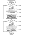
以下は、部品実装ライン10の管理装置80が行う処理の説明である。図7は保管エリア情報更新処理の一例を示すフローチャートである。なお、保管エリア情報は、保管エリア60Aのフィーダ台40にセットされているフィーダ30の取付位置やID情報、収容部品に関する情報でありHDD80cに記憶される。保管エリア情報更新処理では、管理装置80のCPU80aは、まず、保管エリア60Aのフィーダ台40にフィーダ30が新たに取り付けられたか否かを判定する(S100)。CPU80aは、フィーダ30が新たに取り付けられたと判定すると、取り付けられたコネクタ45の位置に基づいて取付位置の位置情報を取得すると共に(S105)、取り付けられたフィーダ30のフィーダ制御装置39からフィーダ30のID情報や収容されている部品種や部品量などのフィーダ情報を取得する(S110)。そして、CPU80aは、位置情報に対応付けてフィーダ情報を登録することで保管エリア情報を更新して(S115)、次のS120の処理に進む。また、CPU80aは、S100でフィーダ30が新たに取り付けられてないと判定すると、S105~S115の処理をスキップして、次のS120の処理に進む。
The following is an explanation of the processing performed by the
次に、管理装置80のCPU80aは、保管エリア60Aのフィーダ台40からフィーダ30が取り外されたか否かを判定し(S120)、フィーダ30が取り外されてないと判定すると、保管エリア情報更新処理を終了する。一方、CPU80aは、フィーダ30が取り外されたと判定すると、取り外されたコネクタ45の位置に基づいて取外位置の位置情報を取得すると共に(S125)、位置情報に対応付けられたフィーダ情報を削除することで保管エリア情報を更新して(S130)、保管エリア情報更新処理を終了する。
Next, the
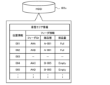
ここで、図8は保管エリア情報の一例を示す説明図である。保管エリア情報には、フィーダ30の取付位置の位置情報に対応付けて、フィーダ30のID情報や部品種の情報、部品量の情報などが記憶される。なお、位置情報は、フィーダ台40の複数のスロット42のうち基準スロット(例えば左端のスロット42)を先頭位置「001」として順に定められている。図8の例では、位置情報が「001」や「002」の位置には、部品種が「A-001」で部品量が「Full」(作業者が補給してから未使用)のフィーダ30が取り付けられていることを示す。また、位置情報が「003」の位置には、フィーダ30が取り付けられていないことを示す。また、位置情報が「004」や「005」の位置には、部品種が「B-005」で部品量が「Empty」(既に部品実装機20で使用済み)のフィーダ30が取り付けられていることを示す。「Empty」のフィーダ30が予め決められた数を超えると、作業者に対し、音声で報知される。なお、保管エリア情報は、部品量に「Full」か「Empty」かを記憶するものに限られず、部品の残数の値を記憶するものなどとしてもよい。また、管理装置80は、作業者の要求に基づいてディスプレイ82に保管エリア情報を視認可能に表示してもよい。なお、各部品実装機20の実装制御装置28は、保管エリア情報と同様に、供給エリア20A内の位置情報とフィーダ情報とを対応付けた供給エリア情報やストックエリア20B内の位置情報とフィーダ情報とを対応付けたストックエリア情報を記憶する。
Here, FIG. 8 is an explanatory diagram showing an example of storage area information. In the storage area information, the ID information of the
図9はフィーダ交換処理の一例を示すフローチャートである。この処理は、フィーダ保管庫60の保管エリア60A内のフィーダ30と、部品実装機20の供給エリア20A内(あるいはストックエリア20B内)のフィーダ30とを交換する場合に実行される。フィーダ30の交換は、管理装置80が基板Sの生産プログラムに基づいて、次の実装処理に必要な部品を収容したフィーダ30を保管エリア60Aから取り外して各部品実装機20の供給エリア20Aに取り付けたり、次の実装処理に不要な部品を収容したフィーダ30を供給エリア20Aから取り外してストックエリア20Bや保管エリア60Aに取り付けたりすることにより行われる。あるいは、フィーダ30の交換は、供給エリア20Aに取り付けられているフィーダ30内の部品残数が値0となって部品実装機20から送信される部品切れ情報を受信したときに、その使用済みのフィーダ30を供給エリア20Aから取り外して保管エリア60Aに取り付けたり、同じ種類の部品を収容したフィーダ30を保管エリア60Aから取り外して供給エリア20Aやストックエリア20Bに取り付けたりすることにより行われる。このように、フィーダ30の交換処理は、フィーダ保管庫60(保管エリア60A)でフィーダ30を着脱する場合と、部品実装機20(供給エリア20A,ストックエリア20B)でフィーダ30を着脱する場合とがある。
Figure 9 is a flowchart showing an example of a feeder replacement process. This process is executed when a
フィーダ交換処理では、管理装置80のCPU80aは、まず、フィーダ保管庫60(保管エリア60A)でフィーダ30を着脱する着脱タイミングであるか否かを判定し(S200)、着脱タイミングでないと判定すると次のS225の処理に進む。一方、CPU80aは、着脱タイミングであると判定すると、保管エリア情報に基づいてフィーダ30を着脱する位置である処理対象位置を設定する(S205)。また、CPU80aは、その処理対象位置でフィーダ30を着脱するために交換ロボット50が移動すべき位置を目標位置に設定する(S210)。例えば、フィーダ保管庫60(保管エリア60A)のフィーダ30を取り外す場合、そのフィーダ30が取り付けられているスロット42の位置(取付位置)が処理対象位置となり、その処理対象位置からフィーダ30の取り外しが可能となる交換ロボット50の位置が目標位置となる。また、使用済みのフィーダ30をフィーダ保管庫60(保管エリア60A)に取り付ける場合、そのフィーダ30を取り付け可能な空きスロット42の位置が処理対象位置となり、その処理対象位置でフィーダ30の取り付けが可能となる交換ロボット50の位置が目標位置となる。CPU80aは、目標位置を設定すると、交換ロボット50を目標位置に移動させる交換ロボット移動処理を実行し(S215)、目標位置で交換ロボット50を駆動制御してフィーダ保管庫60(保管エリア60A)の処理対象位置に対するフィーダ30の着脱処理を行って(S220)、次のS225の処理に進む。
In the feeder replacement process, the
次に、CPU80aは、部品実装機20(供給エリア20A,ストックエリア20B)でフィーダ30を着脱する着脱タイミングであるか否かを判定し(S225)、着脱タイミングでないと判定するとフィーダ交換処理を終了する。一方、CPU80aは、着脱タイミングであると判定すると、処理対象の部品実装機20を特定し(S230)、特定した部品実装機20の供給エリア情報やストックエリア情報に基づいて処理対象位置を設定すると共に(S235)、交換ロボット50の目標位置を設定する(S240)。例えば、部品実装機20(供給エリア20A,ストックエリア20B)のフィーダ30を取り外す場合、そのフィーダ30が取り付けられているスロット42の位置(取付位置)が処理対象位置となり、その処理対象位置でフィーダ30の取り外しが可能となる交換ロボット50の位置が目標位置となる。また、フィーダ30を部品実装機20(供給エリア20A,ストックエリア20B)に取り付ける場合、そのフィーダ30を取り付け可能な空きスロット42の位置が処理対象位置となり、その処理対象位置でフィーダ30の取り付けが可能となる交換ロボット50の位置が目標位置となる。CPU80aは、目標位置を設定すると、交換ロボット50を目標位置に移動させる交換ロボット移動処理を実行し(S245)、目標位置で交換ロボット50を駆動制御して部品実装機20(供給エリア20A,ストックエリア20B)の処理対象位置に対するフィーダ30の着脱処理を行って(S250)、フィーダ交換処理を終了する。なお、S235~S250の処理では、供給エリア20Aとストックエリア20Bとの間でフィーダ30を入れ替える作業を行うものとしてもよい。以下、S215,S245の交換ロボット移動処理を説明する。図10は、交換ロボット移動処理の一例を示すフローチャートである。この処理は、管理装置80からの駆動指令に基づいてロボット制御装置59のCPUが行う。
Next, the
この交換ロボット移動処理では、ロボット制御装置59は、まず、交換ロボット50の進行方向側(目標位置に向かう側)のセンサが作業者(障害物)を検知しているか否かを判定する(S300)。S300の処理は、進行方向が左方向であれば左側監視センサ58aからの検知信号に基づいて行われ、進行方向が右方向であれば右側監視センサ58bからの検知信号に基づいて行われる。ロボット制御装置59は、進行方向側のセンサが作業者を検知していると判定すると、交換ロボット50を停止して(S305)、S300の判定を繰り返す。S305の処理は、交換ロボット50が移動中であれば移動を終了させることにより行われ、交換ロボット50が停止中であればその状態を維持することにより行われる。
In this exchange robot movement process, the
一方、ロボット制御装置59は、進行方向側のセンサが作業者を検知していないと判定すると、交換ロボット50の進行方向がフィーダ保管庫60側(本実施形態では、部品実装ライン10の上流側)であるか否かを判定する(S310)。ロボット制御装置59は、交換ロボット50の進行方向がフィーダ保管庫60側でない(部品実装ライン10の下流側である)と判定すると、所定速度で交換ロボット50を移動させて(S315)、S360の処理に進む。また、ロボット制御装置59は、交換ロボット50の進行方向がフィーダ保管庫60側であると判定すると、保管庫前監視センサ86からの検知信号に基づいて保管庫前範囲11aに作業者がいるか否かを判定する(S320)。ロボット制御装置59は、保管庫前範囲11aに作業者がいると判定すると、エンコーダ57の検出位置に基づいて交換ロボット50の現在位置が隣接範囲11b内であるか否かを判定する(S325)。ロボット制御装置59は、保管庫前範囲11aに作業者がいないと判定したり、保管庫前範囲11aに作業者がいると判定しても交換ロボット50が隣接範囲11b内でない(本実施形態では、非隣接範囲11c内である)と判定したりすると、所定速度で交換ロボット50を移動させる(S330)。また、ロボット制御装置59は、保管庫前範囲11aに作業者がいると判定し、且つ、交換ロボット50が隣接範囲11b内であると判定すると、所定速度よりも遅い低速で交換ロボット50を移動させる(S335)。このように、交換ロボット50が保管庫前範囲11aにいる作業者に近付いていく場合、交換ロボット50を隣接範囲11b内で低速移動させるから、作業者に安全に作業を行わせつつ、交換ロボット50の移動が必要以上に制限されるのを防止することができる。
On the other hand, when the
次に、ロボット制御装置59は、エンコーダ57の検出位置に基づいて交換ロボット50が隣接範囲11bと保管庫前範囲11aとの境界位置に到達したか否かを判定し(S340)、到達してないと判定するとS360の処理に進む。ロボット制御装置59は、交換ロボット50が境界位置に到達したと判定すると、保管庫前監視センサ86からの検知信号に基づいて保管庫前範囲11aに作業者がいるか否かを判定し(S345)、保管庫前範囲11aに作業者がいると判定すると、交換ロボット50を停止して(S350)、S345の判定を繰り返す。S350の処理は、交換ロボット50が移動中であれば移動を終了させることにより行われ、交換ロボット50が停止中であればその状態を維持することにより行われる。このように、保管庫前範囲11aに作業者がいれば、交換ロボット50を隣接範囲11bから保管庫前範囲11aに進入させず、交換ロボット50を保管庫前範囲11aで移動させないようにするから、フィーダ保管庫60にフィーダ30を搬入出する作業者の安全を確保することができる。ここで、例えば、ロボット制御装置50の監視センサ(左側監視センサ58a)の検知範囲は、保管庫前範囲11aを監視する保管庫前監視センサ86の検知範囲よりも狭いものとする。このため、保管庫前監視センサ86からの検知信号に基づいて、保管庫前範囲11aの作業者の安全を適切に確保することができる。また、保管庫前範囲11aは、フィーダ保管庫60の正面の範囲だけでなく隣接する部品実装機20の正面の範囲も含むから、作業者の安全をより確保し易いものとすることができる。
Next, the
S345で、ロボット制御装置59は保管庫前範囲11aに作業者がいないと判定すると、交換ロボット50を所定速度で移動させて保管庫前範囲11aに進入させて(S355)、S360の処理に進む。なお、ロボット制御装置59は、S350で交換ロボット50を停止させた後に、S345で保管庫前監視センサ86が作業者を検知しないと判定した場合、所定時間が経過するまで待機してから交換ロボット50を移動させてもよい。そして、ロボット制御装置59は、交換ロボット50が目標位置に到達したか否かを判定する(S360)。ロボット制御装置59は、交換ロボット50が目標位置に到達してないと判定するとS300に戻り処理を繰り返し、交換ロボット50が目標位置に到達したと判定すると交換ロボット50を停止して(S365)、交換ロボット移動処理を終了する。なお、交換ロボット50が保管庫前範囲11aに進入した後、目標位置に到達する前に作業者を検知すると、S305で移動を停止することになる。
In S345, when the
ここで、本実施形態の構成要素と本発明の構成要素との対応関係を明らかにする。本実施形態のフィーダ30が部品供給ユニットに相当し、部品実装機20が部品実装機に相当し、部品実装ライン10が部品実装ラインに相当し、フィーダ保管庫60がユニット保管庫に相当し、交換ロボット50がユニット交換装置に相当し、図9のフィーダ交換処理を実行する管理装置80と図10の交換ロボット移動処理を実行するロボット制御装置59とが制御装置に相当する。また、基板搬送装置62が搬送装置に相当し、保管庫前監視センサ86が検出器に相当し、管理装置80が管理装置に相当し、廃材搬送装置26が廃材搬送装置に相当する。
Here, the correspondence between the components of this embodiment and the components of the present invention will be clarified. In this embodiment, the
以上説明した部品実装ライン10は、基板の搬送方向に沿って並んだ複数の部品実装機20と、部品実装機20に着脱可能なフィーダ30を複数保管するフィーダ保管庫60と、フィーダ保管庫60と各部品実装機20との間でフィーダ30を交換可能な交換ロボット50とを備え、フィーダ保管庫60が複数の部品実装機20と同じ並びに設置されており、交換ロボット50が基板の搬送方向に沿って移動してフィーダ30を交換する。これにより、作業者はフィーダ保管庫60にフィーダ30を補給しておくだけで、部品実装ライン10の各部品実装機20にフィーダ30を補給することができる。また、各部品実装機20から使用済みのフィーダ30をフィーダ保管庫60に自動で集めることができるため、作業者はフィーダ保管庫60からフィーダ30をまとめて回収することができる。即ち、作業者は、いずれの部品実装機20で使用されるフィーダ30であってもフィーダ保管庫60で補給や回収を行うことができる。また、交換ロボット50がフィーダ保管庫60の前になければ任意のタイミングでフィーダ30の補給や回収を行うことができる。また、作業者が各部品実装機20にフィーダ30を供給するものに比べて、移動中の交換ロボット50が頻繁に停止されるのを防止することができる。この結果、使い勝手のよいフィーダ保管庫60を提供することができる。また、フィーダ保管庫60におけるフィーダ30の保管(収納)本数が、部品実装ライン10で実装される部品の数や部品種に応じて適切な数となるようフィーダ保管庫60を構成することで、フィーダ保管庫60をインライン型の部品倉庫として適切に機能させることができる。
The
また、フィーダ保管庫60は基板搬送装置62を備えるから、フィーダ保管庫60を複数の部品実装機20と同じ並びとなる位置に容易に設置することができる。部品実装ライン10は、フィーダ保管庫60を最も上流側の部品実装機20よりも上流位置に設置するから、フィーダ保管庫60にフィーダ30を搬入出する際に交換ロボット50の移動と干渉するのを抑えることができる。また、部品実装ライン10は、フィーダ保管庫60と部品実装機20とで共通のフィーダ台40を同じ高さ位置に備えており、交換ロボット50は、同じフィーダ移載機構53を用いた共通の動作によりフィーダ保管庫60と部品実装機20とでフィーダ30の着脱を効率よく行うことができる。
In addition, since the
また、部品実装ライン10は、保管庫前監視センサ86が作業者を検知していると、保管庫前範囲11aに交換ロボット50を進入させないから、作業者の安全を確保することができる。また、保管庫前監視センサ86が作業者を検知していると、隣接範囲11b内をフィーダ保管庫60側に向かう交換ロボット50を低速で移動させるから、作業者の安全を阻害しない範囲で交換ロボット50を移動させることができる。また、部品実装ライン10は、フィーダ保管庫60の設置スペース内に管理装置80や回収容器64を配置するから、スペースを効率よく利用することができる。
In addition, when the front-of-
なお、本発明は上述した実施形態に何ら限定されることはなく、本発明の技術的範囲に属する限り種々の態様で実施し得ることはいうまでもない。 It goes without saying that the present invention is not limited to the above-described embodiment, and can be implemented in various forms as long as they fall within the technical scope of the present invention.
例えば、上述した実施形態では、最も上流側の部品実装機20よりも上流位置にフィーダ保管庫60を設置したが、これに限られず、複数の部品実装機20の並び方向で最も下流側の部品実装機20よりも下流位置にフィーダ保管庫60を設置してもよい。あるいは、複数の部品実装機20の並び方向の途中の位置(部品実装機20に挟まれる位置)にフィーダ保管庫60を設置してもよい。また、フィーダ保管庫60は、部品実装ライン10内に1つのみ設置したが、複数設置してもよい。図11は、変形例の部品実装ライン10Bの構成の概略を示す構成図である。図示するように、変形例の部品実装ライン10Bでは、最も上流側の部品実装機20よりも上流位置と、複数の部品実装機20の並び方向の途中の位置(略中間位置)とに、計2つのフィーダ保管庫60が設置されている。この場合、上流側のフィーダ保管庫60と中間位置のフィーダ保管庫60との間の部品実装機20で用いられるフィーダ30は、主に上流側のフィーダ保管庫60で補給や回収し、中間位置のフィーダ保管庫60よりも下流側の部品実装機20で用いられるフィーダ30は、主に中間位置のフィーダ保管庫60で補給や回収するものなどとすることができる。これにより、複数の部品実装機20として多くの部品実装機20が並び、部品実装ライン10Bの全長が長くなる場合でも、交換ロボット50の移動距離が必要以上に長くなるのを防止して、フィーダ30の自動交換の作業効率が低下するのを抑制することができる。なお、フィーダ保管庫60だけでなく、交換ロボット50を複数設置するものとしてもよい。
For example, in the above-described embodiment, the
上述した実施形態では、作業者がフィーダ保管庫60にフィーダ30を搬入出するものとしたが、これに限られず、部品実装機10のライン外からフィーダ30を自動で搬送可能な自動搬送装置を用いてフィーダ保管庫60にフィーダ30を搬入出するものとしてもよい。図12は、変形例の部品実装ライン10C,10Dの構成の概略を示す構成図である。自動搬送装置としては、例えば、図12(a)に示すように、OHT(天井走行式の無人搬送車)90を用いることができる。OHT90によるフィーダ30の搬入出は、搬入出先の上部が開放していることが必要であるが、部品実装機20は、ヘッド22を移動させる構造上、上部を開放するよう構成するのは困難である。フィーダ保管庫60は、そのような制約がなく保管エリア60Aの上部を開放することができるため、OHT90によるフィーダ30の自動搬入出を可能とすることができる。また、自動搬送装置としては、図12(b)に示すように、AGV(床上走行式の無人搬送車)100を用いることができる。AGVが各部品実装機20にフィーダ30を搬入出するものとすると、AGVの移動と交換ロボット50の移動との干渉の問題が頻発することがある。また、AGVによるフィーダ30の搬入出をスムーズなものとするには、AGVの停止位置合わせのガイドを設けることが望ましいが、AGVが各部品実装機20にフィーダ30を搬入出するものとすると各部品実装機20にガイドを設けることになってスペースの問題が生じることがある。変形例のように、AGV100がフィーダ保管庫60にのみフィーダ30を搬入出するものとすることで、保管庫前範囲11aでのみAGV100の移動と交換ロボット50の移動との干渉を防止したり、フィーダ保管庫60にのみガイドを設けたりすればよいから、それらの問題が生じるのを防止することができる。
In the above-described embodiment, the
上述した実施形態では、フィーダ保管庫60の設置スペース内に管理装置80と回収容器64とを配置したが、これに限られず、管理装置80と回収容器64とのうち一方あるいは両方を配置しないものとしてもよい。なお、回収容器64は、廃テープを回収するものに限られず、部品を収容する収容部材(例えばトレイ状の部材)の廃材を回収するものであってもよい。
In the above embodiment, the
上述した実施形態では、保管庫前範囲11aに作業者がいる場合には、隣接範囲11b内をフィーダ保管庫60側に向かう交換ロボット50を所定速度よりも遅い低速で移動させたが、これに限られず、交換ロボット50を所定速度で移動させてもよい。
In the above-described embodiment, when a worker is present in the storage front range 11a, the
上述した実施形態では、保管庫前監視センサ86が保管庫前範囲11aの作業者の有無を検知(監視)したが、これに限られるものではない。例えば、フィーダ保管庫60と隣接する部品実装機20との間に、作業者により引き出し可能な安全柵を設けておき、安全柵が引き出されているか否かを検知するものなどとしてもよい。
In the above embodiment, the storage
上述した実施形態では、保管庫前範囲11aに作業者がいれば交換ロボット50を保管庫前範囲11aに進入させずに停止させたが、このような処理に限られるものではない。例えば、フィーダ交換処理において、保管庫前範囲11aに作業者がいることが検知された場合、保管庫前範囲11a以外の範囲で実行可能な処理を先に行うよう交換ロボット50を制御するものなどとしてもよい。
In the above embodiment, if a worker is present in the storage area 11a, the
上述した実施形態では、交換ロボット50の移動制御において、保管庫前監視センサ86と交換ロボット50の左右の監視センサ58a,58bとを用いたが、これに限られず、交換ロボット50の左右の監視センサ58a,58bのみを用いるものとしてもよい。この場合、左右の監視センサ58a,58bを、それぞれ、第1検知範囲と、第1検知範囲よりも広い第2検知範囲とを有する複数のセンサなどで構成し、第2検知範囲で作業者を検知すると低速で移動し、第1検知範囲で作業者を検知すると停止するものなどとしてもよい。あるいは、保管庫前監視センサ86のみを用いて交換ロボット50の移動制御を行っても、保管庫前範囲11aで作業者が安全に作業することは可能である。
In the above embodiment, the storage
上述した実施形態において、作業者は、フィーダ保管庫60にフィーダ30を一つずつ搬入出してもよいし、フィーダ30を複数まとめて搬入出してもよい。例えば、フィーダ保管庫60の保管エリア60Aには、複数のフィーダ30を一括で着脱可能なマガジンをセット可能に構成しておく。そして、作業者は、マガジンに新しいフィーダ30を複数取り付けて保管エリア60Aに補給したり、保管エリア60Aのマガジンに使用済みのフィーダ30が複数取り付けられるとそのマガジンを回収したりする。この場合、作業者はマガジンを搭載可能な台車を用いて補給や回収を行ってもよい。また、フィーダ保管庫60の保管エリア60Aには、そのようなマガジンが搭載された台車をセット可能に構成し、作業車が台車毎(台車上のマガジン内のフィーダ30を含む)交換してもよい。
In the above-described embodiment, the worker may carry the
上述した実施形態では、部品実装機20がフィーダストックエリア20Bを備えたが、これを備えないものとしてもよい。この場合、交換ロボット50が下部移載エリア50Bを備えないものとしたり、下部移載エリア50Bを交換ロボット50内のフィーダ30のストックエリアとして使用したりしてもよい。また、交換ロボット50は、複数のフィーダ30を収容して複数のフィーダ30をまとめて交換可能に構成してもよい。
In the above-described embodiment, the
本発明は、部品実装ラインの製造産業などに利用可能である。 The present invention can be used in the manufacturing industry, such as component mounting lines.
10,10B,10C,10D 部品実装ライン、11a 保管庫前範囲、11b 隣接範囲、11c 非隣接範囲、12 印刷機、14 印刷検査機、18 X軸レール、20 部品実装機、20A 供給エリア、20B ストックエリア、21 基板搬送装置、22 ヘッド、23 ヘッド移動機構、24 テープダクト、25 テープカッタ、26 テープシュート、27 廃テープ搬送装置、28 実装制御装置、30 フィーダ、32 テープリール、33 テープ送り機構、34 位置決めピン、35 コネクタ、37 レール部材、39 フィーダ制御装置、40 フィーダ台、42 スロット、44 位置決め穴、45 コネクタ、50 交換ロボット、50A 上部移載エリア、50B 下部移載エリア、51 ロボット移動機構、52a X軸モータ、52b ガイドローラ、53 フィーダ移載機構、54 クランプ部、55 Y軸スライダ、55a Y軸モータ、55b Y軸ガイドレール、56a Z軸モータ、56b Z軸ガイドレール、57 エンコーダ、58a 左側監視センサ、58b 右側監視センサ、59 ロボット制御装置、60 フィーダ保管庫、60A 保管エリア、61 筐体、62 基板搬送装置、63A 下部スペース、63B 開口、64 回収容器、65A 収納部、65B 置き台、80 管理装置、80a CPU、80b ROM、80c HDD、80d RAM、82 ディスプレイ、84 入力デバイス、86 保管庫前監視センサ、90 OHT、100 AGV、S 基板。 10, 10B, 10C, 10D component mounting line, 11a storage area, 11b adjacent area, 11c non-adjacent area, 12 printing machine, 14 printing inspection machine, 18 X-axis rail, 20 component mounting machine, 20A supply area, 20B stock area, 21 board transport device, 22 head, 23 head movement mechanism, 24 tape duct, 25 tape cutter, 26 tape chute, 27 waste tape transport device, 28 mounting control device, 30 feeder, 32 tape reel, 33 tape feed mechanism, 34 positioning pin, 35 connector, 37 rail member, 39 feeder control device, 40 feeder table, 42 slot, 44 positioning hole, 45 connector, 50 exchange robot, 50A upper transfer area, 50B lower transfer area, 51 robot movement mechanism, 52a X-axis motor, 52b guide roller, 53 feeder transfer mechanism, 54 clamp unit, 55 Y-axis slider, 55a Y-axis motor, 55b Y-axis guide rail, 56a Z-axis motor, 56b Z-axis guide rail, 57 encoder, 58a left side monitoring sensor, 58b right side monitoring sensor, 59 robot control device, 60 feeder storage, 60A storage area, 61 housing, 62 substrate transport device, 63A lower space, 63B opening, 64 collection container, 65A storage unit, 65B placement stand, 80 management device, 80a CPU, 80b ROM, 80c HDD, 80d RAM, 82 display, 84 input device, 86 storage front monitoring sensor, 90 OHT, 100 AGV, S substrate.
Claims (10)
前記部品供給ユニットを複数保管するユニット保管庫と、
前記複数の部品実装機に取り付けられている前記部品供給ユニットと、前記ユニット保管庫に保管されている前記部品供給ユニットとを交換可能なユニット交換装置と、
前記ユニット交換装置を制御する制御装置と、
を備え、
前記ユニット保管庫は、前記複数の部品実装機と同じ並びに設置され、
前記制御装置は、前記搬送方向に沿った所定の移動範囲を移動して前記部品供給ユニットの交換を行うよう前記ユニット交換装置を制御する
部品実装ライン。 A component mounting line in which a component supply unit is detachably set, and a plurality of component mounters that mount components supplied by the component supply unit onto a mounting object are arranged in a transport direction of the mounting object,
a unit storage facility for storing a plurality of the part supply units;
a unit exchange device capable of exchanging the component supply units attached to the plurality of component mounters with the component supply units stored in the unit storage;
A control device for controlling the unit replacement device;
Equipped with
The unit storage is installed in the same row as the plurality of component mounters,
The control device controls the unit replacement device so as to replace the component supply unit by moving within a predetermined movement range along the conveying direction.
前記ユニット保管庫は、前記複数の部品実装機の並び方向で最も上流側の部品実装機よりも上流位置または最も下流側の部品実装機よりも下流位置に設置される
部品実装ライン。 2. The component mounting line according to claim 1,
The unit storehouse is installed at a position upstream of the most upstream component mounter or at a position downstream of the most downstream component mounter in a line-up direction of the plurality of component mounters.
前記ユニット保管庫は、前記上流位置または前記下流位置に加えて、前記複数の部品実装機の並びにおける途中の位置にも設置される
部品実装ライン。 3. The component mounting line according to claim 2,
The component mounting line, wherein the unit storage is installed at the upstream position or the downstream position, and also at an intermediate position in the row of the plurality of component mounters.
前記ユニット保管庫は、前記実装対象物を前記搬送方向に搬送する搬送装置を備える
部品実装ライン。 4. The component mounting line according to claim 1,
The unit storage includes a transport device that transports the object in the transport direction.
前記ユニット保管庫は、前記部品実装機に前記部品供給ユニットが着脱可能にセットされる構成と共通の構成を有し、
前記ユニット交換装置は、前記部品実装機での前記部品供給ユニットの着脱と、前記ユニット保管庫での前記部品供給ユニットの着脱とを、同じ機構を用いた共通の動作で行う
部品実装ライン。 The component mounting line according to any one of claims 1 to 4,
the unit storage has a configuration common to the configuration in which the component supply unit is detachably set in the component mounter,
a unit exchange device for performing attachment and detachment of the component supply unit in the component mounter and attachment and detachment of the component supply unit in the unit storehouse by a common operation using the same mechanism.
前記ユニット保管庫は、作業者により前記部品供給ユニットを搬入出可能とされ、
前記移動範囲のうち前記ユニット保管庫の正面を含む所定範囲内の作業者の有無を検出する検出器を備え、
前記制御装置は、前記検出器が作業者を検出している場合には、前記所定範囲内で移動しないよう前記ユニット交換装置を制御する
部品実装ライン。 The component mounting line according to any one of claims 1 to 5,
the unit storage is configured so that an operator can carry the part supply unit in and out of the unit storage;
a detector for detecting the presence or absence of a worker within a predetermined range including a front of the unit storage unit within the movement range;
The control device controls the unit replacement device so as not to move within the predetermined range when the detector detects a worker.
前記制御装置は、前記検出器が作業者を検出している場合には、前記検出器が作業者を検出していない場合よりも遅い速度で前記所定範囲を除く前記移動範囲内を移動するよう前記ユニット交換装置を制御可能である
部品実装ライン。 7. The component mounting line according to claim 6,
The control device is capable of controlling the unit replacement device to move within the movement range excluding the predetermined range at a slower speed when the detector detects a worker than when the detector does not detect a worker.
前記ユニット保管庫は、前記部品実装ラインの外から前記部品供給ユニットを自動搬送する自動搬送装置により前記部品供給ユニットを搬入出可能とされる
部品実装ライン。 The component mounting line according to any one of claims 1 to 7,
The component mounting line, wherein the unit storage can carry the component supply unit in and out by an automatic transport device that automatically transports the component supply unit from outside the component mounting line.
前記部品実装機の実装に関する管理を行う管理装置を備え、
前記ユニット保管庫の設置スペースには、前記管理装置を配置可能である
部品実装ライン。 9. The component mounting line according to claim 1,
a management device that manages mounting related to the component mounter,
The management device can be placed in an installation space of the unit storehouse.
前記部品供給ユニットは、前記部品を収容する収容部材を送り出すことにより前記部品を前記部品実装機に供給し、
前記部品供給ユニットから前記部品実装機に前記部品が供給された後の前記収容部材の廃材を前記ユニット保管庫の設置スペースまで搬送する廃材搬送装置と、
を備え、
前記ユニット保管庫の設置スペースには、前記廃材搬送装置が搬送した前記廃材を回収する回収容器を配置可能である
部品実装ライン。 The component mounting line according to any one of claims 1 to 9,
the component supply unit supplies the components to the component mounter by sending out a container that contains the components;
a waste material transport device that transports waste materials of the housing member after the components are supplied from the component supply unit to the component mounter to an installation space of the unit storage;
Equipped with
A collection container for collecting the waste material transported by the waste material transporting device can be placed in an installation space of the unit storehouse.
Priority Applications (2)
| Application Number | Priority Date | Filing Date | Title |
|---|---|---|---|
| JP2024161077A JP7728942B2 (en) | 2019-10-09 | 2024-09-18 | Component Mounting Line |
| JP2025134583A JP2025166140A (en) | 2019-10-09 | 2025-08-13 | Component Mounting Line |
Applications Claiming Priority (5)
| Application Number | Priority Date | Filing Date | Title |
|---|---|---|---|
| JP2019185585A JP6924241B2 (en) | 2015-08-25 | 2019-10-09 | Component mounting line |
| JP2021125333A JP7176063B2 (en) | 2019-10-09 | 2021-07-30 | Component mounting line |
| JP2022179218A JP7436609B2 (en) | 2019-10-09 | 2022-11-09 | Component mounting line and component supply method |
| JP2024017614A JP7618861B2 (en) | 2019-10-09 | 2024-02-08 | Component mounting line and component supply method |
| JP2024161077A JP7728942B2 (en) | 2019-10-09 | 2024-09-18 | Component Mounting Line |
Related Parent Applications (1)
| Application Number | Title | Priority Date | Filing Date |
|---|---|---|---|
| JP2024017614A Division JP7618861B2 (en) | 2019-10-09 | 2024-02-08 | Component mounting line and component supply method |
Related Child Applications (1)
| Application Number | Title | Priority Date | Filing Date |
|---|---|---|---|
| JP2025134583A Division JP2025166140A (en) | 2019-10-09 | 2025-08-13 | Component Mounting Line |
Publications (2)
| Publication Number | Publication Date |
|---|---|
| JP2024166360A true JP2024166360A (en) | 2024-11-28 |
| JP7728942B2 JP7728942B2 (en) | 2025-08-25 |
Family
ID=69170077
Family Applications (6)
| Application Number | Title | Priority Date | Filing Date |
|---|---|---|---|
| JP2019185585A Active JP6924241B2 (en) | 2015-08-25 | 2019-10-09 | Component mounting line |
| JP2021125333A Active JP7176063B2 (en) | 2019-10-09 | 2021-07-30 | Component mounting line |
| JP2022179218A Active JP7436609B2 (en) | 2019-10-09 | 2022-11-09 | Component mounting line and component supply method |
| JP2024017614A Active JP7618861B2 (en) | 2019-10-09 | 2024-02-08 | Component mounting line and component supply method |
| JP2024161077A Active JP7728942B2 (en) | 2019-10-09 | 2024-09-18 | Component Mounting Line |
| JP2025134583A Pending JP2025166140A (en) | 2019-10-09 | 2025-08-13 | Component Mounting Line |
Family Applications Before (4)
| Application Number | Title | Priority Date | Filing Date |
|---|---|---|---|
| JP2019185585A Active JP6924241B2 (en) | 2015-08-25 | 2019-10-09 | Component mounting line |
| JP2021125333A Active JP7176063B2 (en) | 2019-10-09 | 2021-07-30 | Component mounting line |
| JP2022179218A Active JP7436609B2 (en) | 2019-10-09 | 2022-11-09 | Component mounting line and component supply method |
| JP2024017614A Active JP7618861B2 (en) | 2019-10-09 | 2024-02-08 | Component mounting line and component supply method |
Family Applications After (1)
| Application Number | Title | Priority Date | Filing Date |
|---|---|---|---|
| JP2025134583A Pending JP2025166140A (en) | 2019-10-09 | 2025-08-13 | Component Mounting Line |
Country Status (1)
| Country | Link |
|---|---|
| JP (6) | JP6924241B2 (en) |
Families Citing this family (7)
| Publication number | Priority date | Publication date | Assignee | Title |
|---|---|---|---|---|
| JP6924241B2 (en) * | 2015-08-25 | 2021-08-25 | 株式会社Fuji | Component mounting line |
| JP2020000662A (en) * | 2018-06-29 | 2020-01-09 | 株式会社大一商会 | Game machine |
| JP2020000658A (en) * | 2018-06-29 | 2020-01-09 | 株式会社大一商会 | Gaming machine |
| JP7607243B2 (en) * | 2021-02-26 | 2024-12-27 | パナソニックIpマネジメント株式会社 | TAPE CASSETTE SUPPLY DEVICE, COMPONENT MOUNTING SYSTEM, AND TAPE CASSETTE SUPPLY METHOD |
| WO2024029357A1 (en) * | 2022-08-01 | 2024-02-08 | パナソニックIpマネジメント株式会社 | Component supply system, arrangement determination method, control method, management device, and supply robot |
| CN119452323A (en) * | 2022-08-01 | 2025-02-14 | 松下知识产权经营株式会社 | Component supply system, configuration determination method, control method, management device, and supply robot |
| WO2026058415A1 (en) * | 2024-09-13 | 2026-03-19 | 株式会社Fuji | Monitoring system for work device |
Citations (4)
| Publication number | Priority date | Publication date | Assignee | Title |
|---|---|---|---|---|
| WO2014010084A1 (en) * | 2012-07-13 | 2014-01-16 | 富士機械製造株式会社 | Component mounting system |
| WO2014118995A1 (en) * | 2013-02-04 | 2014-08-07 | 富士機械製造株式会社 | Cassette-type feeder replacement system for component-mounting machine |
| WO2015004797A1 (en) * | 2013-07-12 | 2015-01-15 | 富士機械製造株式会社 | Automatic feeder placement control device and control method |
| WO2015037099A1 (en) * | 2013-09-12 | 2015-03-19 | 富士機械製造株式会社 | Substrate work system, work method, and feeder transfer method |
Family Cites Families (11)
| Publication number | Priority date | Publication date | Assignee | Title |
|---|---|---|---|---|
| JPS6156858A (en) * | 1984-08-22 | 1986-03-22 | Om Seisakusho:Kk | Automatic supply device of printed board |
| JP2792956B2 (en) * | 1989-11-10 | 1998-09-03 | 三洋電機株式会社 | Parts supply system |
| JP2853338B2 (en) * | 1990-12-19 | 1999-02-03 | 松下電器産業株式会社 | Component supply device to mounting machine |
| JPH066084A (en) * | 1992-06-19 | 1994-01-14 | Olympus Optical Co Ltd | Automatic electronic part installation equipment |
| JPH06190664A (en) * | 1992-12-28 | 1994-07-12 | Matsushita Electric Ind Co Ltd | Supply method for part/tool and device/cassette therefor |
| JP3769160B2 (en) * | 1992-12-28 | 2006-04-19 | ヤマハ発動機株式会社 | Feeding feeder |
| JP2885626B2 (en) * | 1993-12-21 | 1999-04-26 | 日本電気株式会社 | Automatic component mounting equipment |
| JP2005216946A (en) * | 2004-01-27 | 2005-08-11 | Yamaha Motor Co Ltd | Method and apparatus for managing number of remaining parts of mounting machine |
| JP5304723B2 (en) | 2010-05-17 | 2013-10-02 | 株式会社安川電機 | Self-propelled conveying device and cart conveying method |
| JP5476288B2 (en) * | 2010-12-22 | 2014-04-23 | 株式会社日立製作所 | External setup system for component mounting machines |
| JP6924241B2 (en) * | 2015-08-25 | 2021-08-25 | 株式会社Fuji | Component mounting line |
-
2019
- 2019-10-09 JP JP2019185585A patent/JP6924241B2/en active Active
-
2021
- 2021-07-30 JP JP2021125333A patent/JP7176063B2/en active Active
-
2022
- 2022-11-09 JP JP2022179218A patent/JP7436609B2/en active Active
-
2024
- 2024-02-08 JP JP2024017614A patent/JP7618861B2/en active Active
- 2024-09-18 JP JP2024161077A patent/JP7728942B2/en active Active
-
2025
- 2025-08-13 JP JP2025134583A patent/JP2025166140A/en active Pending
Patent Citations (4)
| Publication number | Priority date | Publication date | Assignee | Title |
|---|---|---|---|---|
| WO2014010084A1 (en) * | 2012-07-13 | 2014-01-16 | 富士機械製造株式会社 | Component mounting system |
| WO2014118995A1 (en) * | 2013-02-04 | 2014-08-07 | 富士機械製造株式会社 | Cassette-type feeder replacement system for component-mounting machine |
| WO2015004797A1 (en) * | 2013-07-12 | 2015-01-15 | 富士機械製造株式会社 | Automatic feeder placement control device and control method |
| WO2015037099A1 (en) * | 2013-09-12 | 2015-03-19 | 富士機械製造株式会社 | Substrate work system, work method, and feeder transfer method |
Also Published As
| Publication number | Publication date |
|---|---|
| JP7436609B2 (en) | 2024-02-21 |
| JP2024036630A (en) | 2024-03-15 |
| JP2025166140A (en) | 2025-11-05 |
| JP2021170680A (en) | 2021-10-28 |
| JP6924241B2 (en) | 2021-08-25 |
| JP7176063B2 (en) | 2022-11-21 |
| JP7618861B2 (en) | 2025-01-21 |
| JP7728942B2 (en) | 2025-08-25 |
| JP2023001272A (en) | 2023-01-04 |
| JP2020014020A (en) | 2020-01-23 |
Similar Documents
| Publication | Publication Date | Title |
|---|---|---|
| JP7618861B2 (en) | Component mounting line and component supply method | |
| US11240949B2 (en) | Component mounting line | |
| EP3780929B1 (en) | Component mounting system | |
| JP7093414B2 (en) | Component mounting system | |
| JP6884950B2 (en) | Component mounting system | |
| JP6850849B2 (en) | Tape feeder storage and component mounting line | |
| JP2024114884A (en) | Parts recovery method | |
| JP6840209B2 (en) | Component mounting line | |
| JP2025085855A (en) | management device | |
| JP2025015668A (en) | Component Mounting System | |
| WO2025238851A1 (en) | Component-mounting system | |
| WO2023067647A1 (en) | Used feeder recovery method and management device, and feeder replacement apparatus |
Legal Events
| Date | Code | Title | Description |
|---|---|---|---|
| A521 | Request for written amendment filed |
Free format text: JAPANESE INTERMEDIATE CODE: A523 Effective date: 20240919 |
|
| A621 | Written request for application examination |
Free format text: JAPANESE INTERMEDIATE CODE: A621 Effective date: 20240919 |
|
| TRDD | Decision of grant or rejection written | ||
| A977 | Report on retrieval |
Free format text: JAPANESE INTERMEDIATE CODE: A971007 Effective date: 20250710 |
|
| A01 | Written decision to grant a patent or to grant a registration (utility model) |
Free format text: JAPANESE INTERMEDIATE CODE: A01 Effective date: 20250715 |
|
| A61 | First payment of annual fees (during grant procedure) |
Free format text: JAPANESE INTERMEDIATE CODE: A61 Effective date: 20250813 |
|
| R150 | Certificate of patent or registration of utility model |
Ref document number: 7728942 Country of ref document: JP Free format text: JAPANESE INTERMEDIATE CODE: R150 |