JP2024158564A - Gas Measuring Devices - Google Patents
Gas Measuring Devices Download PDFInfo
- Publication number
- JP2024158564A JP2024158564A JP2023073866A JP2023073866A JP2024158564A JP 2024158564 A JP2024158564 A JP 2024158564A JP 2023073866 A JP2023073866 A JP 2023073866A JP 2023073866 A JP2023073866 A JP 2023073866A JP 2024158564 A JP2024158564 A JP 2024158564A
- Authority
- JP
- Japan
- Prior art keywords
- corner cube
- laser light
- gas
- angle prism
- measurement device
- Prior art date
- Legal status (The legal status is an assumption and is not a legal conclusion. Google has not performed a legal analysis and makes no representation as to the accuracy of the status listed.)
- Pending
Links
Images
Classifications
-
- G—PHYSICS
- G01—MEASURING; TESTING
- G01N—INVESTIGATING OR ANALYSING MATERIALS BY DETERMINING THEIR CHEMICAL OR PHYSICAL PROPERTIES
- G01N21/00—Investigating or analysing materials by the use of optical means, i.e. using sub-millimetre waves, infrared, visible or ultraviolet light
- G01N21/17—Systems in which incident light is modified in accordance with the properties of the material investigated
- G01N21/25—Colour; Spectral properties, i.e. comparison of effect of material on the light at two or more different wavelengths or wavelength bands
- G01N21/31—Investigating relative effect of material at wavelengths characteristic of specific elements or molecules, e.g. atomic absorption spectrometry
- G01N21/39—Investigating relative effect of material at wavelengths characteristic of specific elements or molecules, e.g. atomic absorption spectrometry using tunable lasers
-
- G—PHYSICS
- G01—MEASURING; TESTING
- G01N—INVESTIGATING OR ANALYSING MATERIALS BY DETERMINING THEIR CHEMICAL OR PHYSICAL PROPERTIES
- G01N21/00—Investigating or analysing materials by the use of optical means, i.e. using sub-millimetre waves, infrared, visible or ultraviolet light
- G01N21/01—Arrangements or apparatus for facilitating the optical investigation
- G01N21/03—Cuvette constructions
- G01N21/031—Multipass arrangements
-
- G—PHYSICS
- G01—MEASURING; TESTING
- G01N—INVESTIGATING OR ANALYSING MATERIALS BY DETERMINING THEIR CHEMICAL OR PHYSICAL PROPERTIES
- G01N2201/00—Features of devices classified in G01N21/00
- G01N2201/06—Illumination; Optics
- G01N2201/061—Sources
- G01N2201/06113—Coherent sources; lasers
-
- G—PHYSICS
- G01—MEASURING; TESTING
- G01N—INVESTIGATING OR ANALYSING MATERIALS BY DETERMINING THEIR CHEMICAL OR PHYSICAL PROPERTIES
- G01N2201/00—Features of devices classified in G01N21/00
- G01N2201/06—Illumination; Optics
- G01N2201/066—Modifiable path; multiple paths in one sample
- G01N2201/0666—Selectable paths; insertable multiple sources
-
- G—PHYSICS
- G02—OPTICS
- G02B—OPTICAL ELEMENTS, SYSTEMS OR APPARATUS
- G02B5/00—Optical elements other than lenses
- G02B5/12—Reflex reflectors
- G02B5/122—Reflex reflectors cube corner, trihedral or triple reflector type
Landscapes
- Physics & Mathematics (AREA)
- Analytical Chemistry (AREA)
- Spectroscopy & Molecular Physics (AREA)
- Health & Medical Sciences (AREA)
- Life Sciences & Earth Sciences (AREA)
- Chemical & Material Sciences (AREA)
- Biochemistry (AREA)
- General Health & Medical Sciences (AREA)
- General Physics & Mathematics (AREA)
- Immunology (AREA)
- Pathology (AREA)
- Optics & Photonics (AREA)
- Investigating Or Analysing Materials By Optical Means (AREA)
- Optical Measuring Cells (AREA)
Abstract
Description
本開示は、ガス測定装置に関する。 This disclosure relates to a gas measurement device.
従来、ガスの濃度を測定する方法として、レーザ吸収分光法が知られている。レーザ吸収分光法は、ガス中の分子が特定波長の光を吸収するという特性を利用して、ガス中を通過したレーザの吸光度を測定することによって、ガスの濃度を測定する方法である。 Laser absorption spectroscopy is a method for measuring gas concentration. Laser absorption spectroscopy utilizes the property that molecules in a gas absorb light of a specific wavelength, and measures the concentration of a gas by measuring the absorbance of a laser that passes through the gas.
レーザ吸収分光法は、ガスを通過するレーザの光路長が長いほど測定精度が高くなる。配管、タンクなどの中のガスの濃度を測定する場合、配管、タンクなどの大きさには限りがあるため、レーザ光を複数回往復させることによって光路長を長くしてガスの濃度を測定する多重反射の方法が知られている。 In laser absorption spectroscopy, the longer the optical path length of the laser passing through the gas, the higher the measurement accuracy. When measuring the concentration of gas in pipes, tanks, etc., since the size of the pipes, tanks, etc. is limited, a multiple reflection method is known in which the optical path length is increased by making the laser light go back and forth multiple times to measure the gas concentration.
例えば、特許文献1は、多重反射の方法としてヘリオットセルを用いた構成を開示している。
For example,
多重反射を利用したレーザ吸収分光法の課題として、測定に用いられる部品の位置が変動した際の測定の安定性、レーザ光が反射される際の光量の減衰などの各種特性を改善させることが挙げられる。 Challenges for laser absorption spectroscopy using multiple reflections include improving various characteristics such as the stability of measurements when the position of the parts used in the measurement changes and the attenuation of the amount of light when the laser light is reflected.
そこで、本開示は、多重反射を利用したレーザ吸収分光法における各種特性を改善することができるガス測定装置を提供することを目的とする。 Therefore, the present disclosure aims to provide a gas measurement device that can improve various characteristics in laser absorption spectroscopy that utilizes multiple reflections.
幾つかの実施形態に係るガス測定装置は、レーザ吸収分光法によってガスの濃度を測定するガス測定装置であって、第1のコーナーキューブ又は第1の直角プリズムと、前記第1のコーナーキューブ又は前記第1の直角プリズムに対向して配置された第2のコーナーキューブ又は第2の直角プリズムと、前記第1のコーナーキューブ又は前記第1の直角プリズムにレーザ光を出射するレーザ光源と、前記第1のコーナーキューブ又は前記第1の直角プリズムと前記第2のコーナーキューブ又は前記第2の直角プリズムとの間で被測定ガスを通過して複数回反射された前記レーザ光を受光する受光素子とを備え、前記第2のコーナーキューブ又は前記第2の直角プリズムは、前記第1のコーナーキューブ又は前記第1の直角プリズムの入射位置と出射位置を中心とする入出射光に平行な中心線と前記第2のコーナーキューブ又は前記第2の直角プリズムの入射位置と出射位置を中心とする入出射光に平行な中心線とがずれるように配置されている。このようなガス測定装置によれば、多重反射を利用したレーザ吸収分光法における各種特性を改善することが可能である。 A gas measurement device according to some embodiments is a gas measurement device that measures the concentration of a gas by laser absorption spectroscopy, and includes a first corner cube or a first right-angle prism, a second corner cube or a second right-angle prism arranged opposite the first corner cube or the first right-angle prism, a laser light source that emits laser light to the first corner cube or the first right-angle prism, and a light receiving element that receives the laser light that passes through the gas to be measured and is reflected multiple times between the first corner cube or the first right-angle prism and the second corner cube or the second right-angle prism, and the second corner cube or the second right-angle prism is arranged such that a center line parallel to the incident and exiting light centered on the entrance and exit positions of the first corner cube or the first right-angle prism is misaligned with a center line parallel to the incident and exiting light centered on the entrance and exit positions of the second corner cube or the second right-angle prism. Such a gas measurement device can improve various characteristics in laser absorption spectroscopy that uses multiple reflections.
一実施形態に係るガス測定装置において、前記第1のコーナーキューブ又は前記第1の直角プリズムの前記中心線と前記第2のコーナーキューブ又は前記第2の直角プリズムの前記中心線とがずれている距離によって、前記第1のコーナーキューブ又は前記第1の直角プリズムと前記第2のコーナーキューブ又は前記第2の直角プリズムとの間で前記レーザ光が反射される回数を調整可能であってもよい。これにより、レーザ光が反射される回数を容易に調整することができる。 In one embodiment of the gas measurement device, the number of times the laser light is reflected between the first corner cube or the first right-angle prism and the second corner cube or the second right-angle prism may be adjustable depending on the distance by which the center line of the first corner cube or the first right-angle prism is offset from the center line of the second corner cube or the second right-angle prism. This makes it easy to adjust the number of times the laser light is reflected.
一実施形態に係るガス測定装置において、前記第1のコーナーキューブ又は前記第1の直角プリズムの入射面、及び、前記第2のコーナーキューブ又は前記第2の直角プリズムの入射面は、前記レーザ光源が前記第1のコーナーキューブ又は前記第1の直角プリズムに前記レーザ光を出射する方向に垂直な平面に対して傾いていてもよい。これにより、入射面からの不要反射による影響を低減することができる。 In one embodiment of the gas measurement device, the entrance surface of the first corner cube or the first right-angle prism and the entrance surface of the second corner cube or the second right-angle prism may be tilted with respect to a plane perpendicular to the direction in which the laser light source emits the laser light to the first corner cube or the first right-angle prism. This can reduce the effects of unwanted reflections from the entrance surfaces.
一実施形態に係るガス測定装置において、前記第1のコーナーキューブ又は前記第1の直角プリズムの入射面、及び、前記第2のコーナーキューブ又は前記第2の直角プリズムの入射面は、内部に前記被測定ガスを有する配管に設けられた窓ガラスに密着していてもよい。これにより、第1のコーナーキューブ又は第1の直角プリズムの入射面、及び、第2のコーナーキューブ又は第2の直角プリズムの入射面と、配管に設けられた窓ガラスとの間に間隙ができることを防ぐことができる。 In one embodiment of the gas measurement device, the entrance surface of the first corner cube or the first right-angle prism and the entrance surface of the second corner cube or the second right-angle prism may be in close contact with a window glass provided in a pipe having the gas to be measured inside. This makes it possible to prevent gaps from being formed between the entrance surface of the first corner cube or the first right-angle prism and the entrance surface of the second corner cube or the second right-angle prism and the window glass provided in the pipe.
一実施形態に係るガス測定装置において、前記第1のコーナーキューブ又は前記第1の直角プリズムの前記中心線と前記第2のコーナーキューブ又は前記第2の直角プリズムの前記中心線とをずらしている方向を第1の方向、前記第1のコーナーキューブ又は前記第1の直角プリズムに前記レーザ光が入射される方向を第3の方向、前記第1の方向及び前記第3の方向に直交する方向を第2の方向とすると、前記レーザ光源は、前記第2の方向に中心から所定の距離だけずらした位置に配置されていてもよい。これにより、ガス測定装置は、ガス分布の広い範囲のガス濃度を測定することが可能となる。 In one embodiment of the gas measuring device, the direction in which the center line of the first corner cube or the first right-angle prism is offset from the center line of the second corner cube or the second right-angle prism is defined as a first direction, the direction in which the laser light is incident on the first corner cube or the first right-angle prism is defined as a third direction, and the direction perpendicular to the first direction and the third direction is defined as a second direction. The laser light source may be positioned at a position offset from the center by a predetermined distance in the second direction. This enables the gas measuring device to measure gas concentrations over a wide range of gas distribution.
一実施形態に係るガス測定装置において、前記レーザ光源は、前記第1のコーナーキューブ又は前記第1の直角プリズムの入射面に対して斜めに前記レーザ光を出射してもよい。これにより、レーザ光源から出射するレーザ光のプリズムへの入射角度を変更することで、反射回数を調整することができ、またプリズム入出射面で発生する不要反射による光学干渉の影響が低減できる。 In one embodiment of the gas measurement device, the laser light source may emit the laser light at an angle to the entrance surface of the first corner cube or the first right-angle prism. This allows the number of reflections to be adjusted by changing the angle of incidence of the laser light emitted from the laser light source to the prism, and also reduces the effects of optical interference caused by unwanted reflections that occur at the prism entrance and exit surfaces.
本開示によれば、多重反射を利用したレーザ吸収分光法における各種特性を改善することができるガス測定装置を提供することができる。 This disclosure provides a gas measurement device that can improve various characteristics in laser absorption spectroscopy using multiple reflections.
(ヘリオットセル)
最初に、従来のヘリオットセルを用いたガス測定装置について説明する。図1は、従来のヘリオットセルを用いたガス測定装置の概略構成を示す図である。
(Heriot Cell)
First, a conventional gas measurement device using a Herriott cell will be described. Fig. 1 is a diagram showing a schematic configuration of a conventional gas measurement device using a Herriott cell.
図1に示すヘリオットセルを用いたガス測定装置は、第1の凹面鏡101と、第2の凹面鏡102と、レーザ光源103と、受光素子104とを備える。
The gas measurement device using the Herriott cell shown in FIG. 1 includes a first
第1の凹面鏡101と第2の凹面鏡102とは対向して配置される。第1の凹面鏡101と第2の凹面鏡102との間には、測定対象である被測定ガスがある。
The first
レーザ光源103は、第2の凹面鏡102に設けられた穴を通過するようにレーザ光を出射する。レーザ光は、第1の凹面鏡101及び第2の凹面鏡102によって複数回反射され、第2の凹面鏡102に設けられた穴から外に出る。
The
受光素子104は、第2の凹面鏡102に設けられた穴から外に出できたレーザ光を受光する。
The light receiving
ヘリオットセルを用いたガス測定装置において、レーザ光が被測定ガスを通過する光路長は、第1の凹面鏡101及び第2の凹面鏡102によって複数回反射されることによって長い距離となる。
In a gas measurement device using a Herriott cell, the optical path length that the laser light travels through the gas to be measured becomes long because the laser light is reflected multiple times by the first
図1に示すように、被測定ガスの端から端までの距離である測定距離が短い場合であっても、レーザ光を複数回反射させることにより、ヘリオットセルを用いたガス測定装置は、被測定ガスを通過するレーザ光の光路長を長くすることができる。以後、「測定距離」との用語を、被測定ガスの端から端までの距離という意味で用いる場合がある。 As shown in Figure 1, even if the measurement distance, which is the distance from one end of the measured gas to the other end, is short, a gas measurement device using a Herriott cell can increase the optical path length of the laser light passing through the measured gas by reflecting the laser light multiple times. Hereinafter, the term "measurement distance" may be used to mean the distance from one end of the measured gas to the other.
このように、第1の凹面鏡101及び第2の凹面鏡102によってレーザ光を複数回反射させて光路長を長くすることで、ヘリオットセルを用いたガス測定装置は、ガスの濃度を精度良く測定することができる。
In this way, by reflecting the laser light multiple times by the first
図2は、従来のヘリオットセルを用いたガス測定装置によって、配管200内の被測定ガスの濃度を測定する場合の概略構成を示す図である。
Figure 2 shows a schematic diagram of a gas measurement device using a conventional Herriott cell for measuring the concentration of a measurement gas in a
図2に示す例においては、内部に被測定ガスがある配管200に窓ガラス210が設けられている。窓ガラス210は、被測定ガスを測定するための測定用の窓として、配管200に設けられている。
In the example shown in FIG. 2, a
図2に示す例においては、第1の凹面鏡101及び第2の凹面鏡102は、窓ガラス210に接するように配置されている。
In the example shown in FIG. 2, the first
図1及び図2に示したような、従来のヘリオットセルを用いたガス測定装置には、以下のような課題がある。 Conventional gas measurement devices using Herriott cells, such as those shown in Figures 1 and 2, have the following problems:
<課題1>
ヘリオットセルにおいて、レーザ光源103が出射するレーザ光の光路は、レーザ光の入射角、レーザ光源103の位置、測定距離、反射回数、第1の凹面鏡101及び第2の凹面鏡102の位置、第1の凹面鏡101及び第2の凹面鏡102の曲面率などのようなパラメータに依存する。振動、温度などに起因して歪みなどの物理的な変動があると、上記パラメータは変動するが、そうすると光路も変動してしまう。特に、第1の凹面鏡101及び第2の凹面鏡102の角度が変動すると、反射の度に影響が累積するため、反射回数に比例して光路の変動が大きくなる。光路の変動は、光路長、光量の変動及び受光素子104の受光位置の変動となり、測定ノイズの増加、測定値の変動などをもたらす。
<
In the Herriott cell, the optical path of the laser light emitted by the
<課題2>
第1の凹面鏡101及び第2の凹面鏡102の反射面にはミラーコーティングが施されている。このミラーコーティングの材料は、すべてを反射させることが困難であるため、第1の凹面鏡101及び第2の凹面鏡102に入射されたレーザ光の一部は透過する。したがって、第1の凹面鏡101及び第2の凹面鏡102によって反射される度に、レーザ光の光量は減衰し、その分、受光素子104が受光するレーザ光の光量は低減する。レーザ光の透過によるレーザ光の光量の低減は、SN比が悪化するため、測定ノイズの増加、測定値の変動などをもたらす。
<
A mirror coating is applied to the reflecting surfaces of the first
<課題3>
課題1において示した各パラメータは、測定距離に応じた値に調整する必要がある。そのため、大きさの異なる配管、タンクにおいて内部のガス濃度を測定する場合、その都度、各パラメータを調整することが必要となる。特に、第1の凹面鏡101及び第2の凹面鏡102の曲面率を変えるためには、別の第1の凹面鏡101及び別の第2の凹面鏡102を用意することが必要となるため、汎用的に部品を使用して測定することが困難である。
<
Each parameter shown in
<課題4>
反射回数を増やしてレーザ光の光路長を長くすると、基本的にはガスの濃度を精度良く測定することができる。しかしながら、光路長を長くし過ぎると、被測定ガス中に含まれるダストの影響及びレーザ光のビーム径の形状悪化などによるレーザ光の光量低下により、測定ノイズの増加、測定値の変動をもたらす。そのため、反射回数を適切な回数に調整することが望ましいが、その場合、課題1において示した各パラメータを調整する必要がある。しかしながら、ヘリオットセルを用いた構成は各パラメータの調整が容易でないため、反射回数の調整が容易ではない。
<
Increasing the number of reflections to lengthen the optical path length of the laser light basically allows for accurate measurement of the gas concentration. However, if the optical path length is made too long, the influence of dust contained in the measured gas and the deterioration of the shape of the beam diameter of the laser light will reduce the amount of laser light, resulting in increased measurement noise and fluctuations in the measured value. Therefore, it is desirable to adjust the number of reflections to an appropriate number, but in that case, it is necessary to adjust each parameter shown in
<課題5>
レーザ光源103のレーザ光の入射角、レーザ光の入射位置の調整は、反射の度に反射角度及び反射位置の変化量が累積し調整感度が増加する。このため、反射回数を増やすと、光軸の調整に対する調整感度が大きくなり、レーザ光源103の光軸の微調整が困難となる。
<
The adjustment sensitivity of the incident angle and the incident position of the laser light from the
<課題6>
ヘリオットセルは、第1の凹面鏡101及び第2の凹面鏡102を使用しているため、レーザ光の光路長を算出する際、凹面を考慮して算出する必要がある。そのため、光路長を算出するために複雑な計算が必要となる。
<Challenge 6>
Since the Herriott Cell uses the first
<課題7>
図2に示したように、ヘリオットセルにおいて第1の凹面鏡101及び第2の凹面鏡102を使用する場合、配管200の測定用の窓ガラス210に第1の凹面鏡101及び第2の凹面鏡102を設置する場合がある。この場合、第1の凹面鏡101及び第2の凹面鏡102は凹面形状であるため、第1の凹面鏡101及び第2の凹面鏡102と窓ガラス210との間に間隙220ができてしまう。間隙220に存在する気体は測定対象である被測定ガスとは異なる気体であるため、間隙220を通過する光路長の分が誤差要因となってしまう。特に、被測定ガスの濃度が小さい場合、測定距離が短い場合などは、間隙220による誤差の影響が大きくなる。
<Challenge 7>
As shown in Fig. 2, when the first
<課題8>
図1に示すように、第2の凹面鏡102には、レーザ光源103が出射するレーザ光が通過することを可能とし、また、受光素子104が受光するレーザ光を通過させることを可能とする穴を設けることが必要である。そのため、第2の凹面鏡102には、穴加工を追加する必要があり、加工費が高価となる。
<Challenge 8>
1, it is necessary to provide the second
<課題9>
課題2において記載したように、第1の凹面鏡101及び第2の凹面鏡102の反射面にはミラーコーティングを施すことが必要である。レーザ光が第1の凹面鏡101及び第2の凹面鏡102によって反射される際の光量の減衰を抑制するためには、ミラーコーティングの材料として、高反射率の材料を用いることが必要となり、加工費が高価となる。
<Challenge 9>
As described in
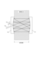
(本開示のガス測定装置)
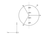
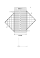
図3は、一実施形態に係るガス測定装置1の概略構成を示す図である。ガス測定装置1は、ヘリオットセルにおける上述の課題1~9を解消することを目的とするガス測定装置である。図3を参照して、一実施形態に係るガス測定装置1の構成及び機能について説明する。
(Gas measurement device of the present disclosure)
Fig. 3 is a diagram showing a schematic configuration of a
ガス測定装置1は、レーザ吸収分光法によってガスの濃度を測定する装置である。図1においては、測定対象のガスを被測定ガスとして示している。また、本実施形態においても、「測定距離」との用語を、被測定ガスの端から端までの距離という意味で用いる場合がある。
The
ガス測定装置1は、第1のコーナーキューブ10と、第2のコーナーキューブ20と、レーザ光源30と、受光素子40とを備える。
The
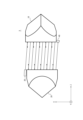
第1のコーナーキューブ10及び第2のコーナーキューブ20は、先端部分が3つの平面でカットされたプリズムである。第1のコーナーキューブ10及び第2のコーナーキューブ20は、再帰反射の特性を有する。再帰反射の特性とは、光がどのような方向から入射されても、入射された方向に対して180度の方向に光を反射する特性である。第1のコーナーキューブ10及び第2のコーナーキューブ20は、ガラスで構成されていてよい。
The
第1のコーナーキューブ10と第2のコーナーキューブ20との間に測定対象である被測定ガスがある。第2のコーナーキューブ20は、第1のコーナーキューブ10に対向して配置されている。図3に示す例においては、第1のコーナーキューブ10の入射面はXY平面と平行である。また、第2のコーナーキューブ20の入射面もXY平面と平行である。第1のコーナーキューブ10の入射面及び第2のコーナーキューブ20の入射面は、被測定ガスに接している。
The gas to be measured is located between the
レーザ光源30は、第1のコーナーキューブ10にレーザ光を出射する。レーザ光源30は、被測定ガス成分の吸光スペクトルを測定可能な波長を有するレーザ光を出射する。レーザ光源30は、例えば、ランプ光源、LED(Light-Emitting Diode)光源などであってよい。
The
受光素子40は、第1のコーナーキューブ10と第2のコーナーキューブ20との間で被測定ガスを通過して複数回反射されたレーザ光を受光する。受光素子40は、例えばフォトダイオードであってよい。
The
受光素子40が受光したレーザ光の強度からレーザ光の吸光度を算出することができる。また、レーザ光の吸光度から被測定ガスの濃度を算出することができる。受光素子40は、演算装置に接続されていてよい。演算装置は、受光素子40が測定したレーザ光の強度を受光素子40から取得し、レーザ光の吸光度及び被測定ガスの濃度を算出することができる。演算装置は、専用のコンピュータであってもよいし、汎用のPC(Personal Computer)、サーバなどであってもよい。
The absorbance of the laser light can be calculated from the intensity of the laser light received by the
図3に示すように、第1のコーナーキューブ10及び第2のコーナーキューブ20は、第1のコーナーキューブ10の中心線L1と第2のコーナーキューブ20の中心線L2とがずれるように配置されている。
As shown in FIG. 3, the
第1のコーナーキューブ10の中心線とは、第1のコーナーキューブ10の入射面に入射するレーザの入射位置と反射され出射位置の中心点を通る入射レーザ光と平行な線である。第2のコーナーキューブ20の中心線とは、第2のコーナーキューブ20の入射面のに入射するレーザの入射位置と反射された出射位置の中心点を通る入射レーザ光と平行な線である。
The center line of the
第1のコーナーキューブ10と第2のコーナーキューブ20とは、X方向にずらして配置される。この際、レーザ光の光路が第1のコーナーキューブ10又は第2のコーナーキューブ20の中心点を通らないように、ずらし量は調整されている。図3に示す例においては、第1のコーナーキューブ10の中心線L1と、第2のコーナーキューブ20の中心線L2とがX方向に距離Bだけ離れるように、第1のコーナーキューブ10及び第2のコーナーキューブ20が配置されている。中心線L1と中心線L2との間の距離Bは、第1のコーナーキューブ10及び第2のコーナーキューブ20によってレーザ光が反射される回数に関連づけられる。
The
例えば、中心線L1と中心線L2との間の距離Bと、反射回数とは、下記の式(1)のように関連づけられる。
B=φ/(n-1) (1)
ここで、φは第1のコーナーキューブ10及び第2のコーナーキューブ20の直径であり、nは、第1のコーナーキューブ10と第2のコーナーキューブ20との間の多重反射で得られる光路の本数であり、(n―1)が反射回数である。
For example, the distance B between the center line L1 and the center line L2 and the number of reflections are related to each other as shown in the following formula (1).
B=φ/(n-1) (1)
Here, φ is the diameter of the
例えば、第1のコーナーキューブ10及び第2のコーナーキューブ20の直径が50mmであり、光路の本数を5本とする場合、B=12.5mmとなるように、中心線L1と中心線L2との間の距離Bを調整すればよい。
For example, if the diameter of the
レーザ光源30のX方向の位置は、第1のコーナーキューブ10のX軸正方向側のエッジから、距離AだけX軸の負方向側の位置であってよい。距離Aは、例えば、距離Bの1/2の距離であってよい。
The position of the
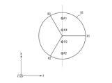
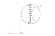
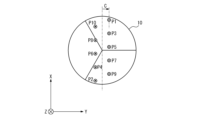
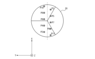
続いて、図3、図4A、図4B及び図5を参照して、レーザ光源30から出射されたレーザ光の光路について説明する。図4Aは、図3の第1のコーナーキューブ10をZ軸負方向側から見た図である。図4Bは、図3の第2のコーナーキューブ20を、Z軸正方向側から見た図である。図5は、第1のコーナーキューブ10が入射光を反射する様子を示す図である。
Next, the optical path of the laser light emitted from the
なお、図4Aにおいて、R1~R3は、第1のコーナーキューブ10の3つの平面の境界、すなわち稜線を示す。また、図4Bにおいても同様に、R1~R3は、第2のコーナーキューブ20の3つの平面の境界、すなわち稜線を示す。
In FIG. 4A, R1 to R3 indicate the boundaries, or ridgelines, of the three planes of the
第1のコーナーキューブ10は、上述したように、再帰反射の特性を有する。そのため、図5に示すように、第1のコーナーキューブ10に入射された入射光は、入射光の方向に対して180度の方向に出射光として出射される。
As described above, the
図3、図4A及び図4Bを参照すると、レーザ光源30から出射されたレーザ光は、被測定ガス中の光路P1を通って第1のコーナーキューブ10に入射される。
Referring to Figures 3, 4A, and 4B, the laser light emitted from the
被測定ガス中の光路P1を通って第1のコーナーキューブ10に入射されたレーザ光は、第1のコーナーキューブ10の中心点に対して点対称の位置で反射されて、第2のコーナーキューブ20に向けて出射される。第2のコーナーキューブ20に向けて出射されたレーザ光は、被測定ガス中の光路P2を通る。
The laser light that is incident on the
被測定ガス中の光路P2を通ったレーザ光は、第2のコーナーキューブ20に入射される。この際、第2のコーナーキューブ20は、第1のコーナーキューブ10よりも距離BだけX軸負方向にずれた位置に配置されているため、光路P2を通ったレーザ光は、第2のコーナーキューブ20の中心に近い位置に入射される。
The laser light that has passed through optical path P2 in the gas to be measured is incident on the
被測定ガス中の光路P2を通って第2のコーナーキューブ20に入射されたレーザ光は、第2のコーナーキューブ20の中心点に対して点対称の位置で反射されて、第1のコーナーキューブ10に向けて出射される。第1のコーナーキューブ10に向けて出射されたレーザ光は、被測定ガス中の光路P3を通る。
The laser light that is incident on the
被測定ガス中の光路P3を通ったレーザ光は、第1のコーナーキューブ10に入射される。この際、P3を通ったレーザ光は、第1のコーナーキューブ10の中心点よりもX軸負方向側の位置に入射される。
The laser light that passes through optical path P3 in the gas to be measured is incident on the
被測定ガス中の光路P3を通って第1のコーナーキューブ10に入射されたレーザ光は、第1のコーナーキューブ10の中心点に対して点対称の位置で反射されて、第2のコーナーキューブ20に向けて出射される。第2のコーナーキューブ20に向けて出射されたレーザ光は、被測定ガス中の光路P4を通る。
The laser light that is incident on the
被測定ガス中の光路P4を通ったレーザ光は、第2のコーナーキューブ20に入射される。この際、第2のコーナーキューブ20は、第1のコーナーキューブ10よりも距離BだけX軸負方向にずれた位置に配置されているため、光路P4を通ったレーザ光は、第2のコーナーキューブ20の中心から遠い位置に入射される。
The laser light that has passed through optical path P4 in the gas to be measured is incident on the
被測定ガス中の光路P4を通って第2のコーナーキューブ20に入射されたレーザ光は、第2のコーナーキューブ20の中心点に対して点対称の位置で反射されて、受光素子40に向けて出射される。受光素子40に向けて出射されたレーザ光は、被測定ガス中の光路P5を通る。
The laser light that is incident on the
被測定ガス中の光路P5を通ったレーザ光は、受光素子40に入射される。
The laser light that passes through the optical path P5 in the gas to be measured is incident on the
図3に示すように、レーザ光源30から出射されたレーザ光は、光路P1~光路P3までは、時計回りで反射されることを繰り返し、光路P4~光路P5までは、反時計回りで反射されることを繰り返す。また、レーザ光源30から出射されたレーザ光は、被測定ガス中を5回通過するので、被測定ガス中を通過するレーザ光の光路長は、測定距離の5倍となる。
As shown in FIG. 3, the laser light emitted from the
なお、第1のコーナーキューブ10及び第2のコーナーキューブ20の稜線R1~R3は、稜線エッジ部で不要な散乱を発生させる原因となるため、図4A及び図4Bに示すように、光路P1~光路P5は、稜線R1~R3によって反射されない経路を通ることが望ましい。還元すれば、Z軸を中心として第1のコーナーキューブ10を回転させた角度は、光路P1~P4が稜線R1~R3を通らないような角度に調整されている。また、Z軸を中心として第2のコーナーキューブ20を回転させた角度は、光路P2~P5が稜線R1~R3を通らないような角度に調整されている。
In addition, since the ridgelines R1 to R3 of the
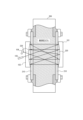
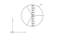
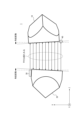
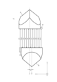
図6、図7A及び図7Bに、一実施形態に係るガス測定装置1を光路の本数が11本になるように調整した場合の概略構成を示す。図7Aは、図6の第1のコーナーキューブ10をZ軸負方向側から見た図である。図7Bは、図6の第2のコーナーキューブ20を、Z軸正方向側から見た図である。
Figures 6, 7A, and 7B show a schematic configuration of a
上述の式(1)を用いて計算すると、第1のコーナーキューブ10及び第2のコーナーキューブ20の直径が50mmであり、光路の本数を11本とする場合、距離Bは5mmと算出される。この場合、距離Aは、A=5/2=2.5mmであってよい。
When calculating using the above formula (1), if the diameter of the
上述の計算に基づいて、第1のコーナーキューブ10の中心線L1と、第2のコーナーキューブ20の中心線L2とがX方向に距離B、すなわち5mm離れるように調整すると、レーザ光源30が出射したレーザ光は、光路の本数が11本になるように反射されて受光素子40に入射される。
Based on the above calculations, when the center line L1 of the
この際、図6に示すように、レーザ光源30から出射されたレーザ光は、光路P1~光路P6までは、時計回りで反射されることを繰り返し、光路P7~光路P11までは、反時計回りで反射されることを繰り返す。また、レーザ光源30から出射されたレーザ光は、被測定ガス中を11回通過するので、被測定ガス中を通過するレーザ光の光路長は、測定距離の11倍となる。
At this time, as shown in FIG. 6, the laser light emitted from the
このように、一実施形態に係るガス測定装置1は、第1のコーナーキューブ10及び第2のコーナーキューブ20によってレーザ光源30が出射したレーザ光を複数回反射するため、被測定ガスを通過するレーザ光の光路長を長くすることができる。
In this way, in the
また、一実施形態に係るガス測定装置1は、第1のコーナーキューブ10の中心線L1と、第2のコーナーキューブ20の中心線L2とのX方向のずれである距離Bを調整するだけで、容易に光路の本数を調整することができる。
In addition, the
ここで、一実施形態に係るガス測定装置1の効果について、上述したヘリオットセルの課題1~9に対応させて、効果1~9として説明する。
Here, the effects of the
<効果1>
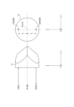
図8に、一実施形態に係るガス測定装置1において、第1のコーナーキューブ10及び第2のコーナーキューブ20に角度変動があった場合の様子を示す。図8に示す例においては、第1のコーナーキューブ10及び第2のコーナーキューブ20の双方が、XY平面に対して傾いている。このような場合であっても、第1のコーナーキューブ10及び第2のコーナーキューブ20は再帰反射の特性を有するため、第1のコーナーキューブ10及び第2のコーナーキューブ20によって反射されるレーザ光はZ軸に対して平行を保つ。すなわち、第1のコーナーキューブ10及び第2のコーナーキューブ20に角度変動があっても光軸が変動しない。したがって、レーザ光が複数回反射されても光路変動が累積しない。このように、一実施形態に係るガス測定装置1は、振動、温度などに起因する歪みなどの物理的な変動からの影響を受けにくく安定性が高い。また、一実施形態に係るガス測定装置1は、振動、温度などに起因する歪みなどの物理的な変動からの影響を受けにくいため、調整が容易であり、特別な加工をして調整するといったことが不要である。
<
FIG. 8 shows the state when the
<効果2>
第1のコーナーキューブ10及び第2のコーナーキューブ20においては、レーザ光が反射面を透過することによる光量の減衰は発生しない。第1のコーナーキューブ10及び第2のコーナーキューブ20は、ガラスで構成されており、3つの平面においてレーザ光を反射する。この際、3つの平面へのレーザ光の入射角は臨界角より大きい角度であるため、3つの平面における反射は全反射となるからである。
<
In the
<効果3>
一実施形態に係るガス測定装置1において、第1のコーナーキューブ10、第2のコーナーキューブ20、レーザ光源30及び受光素子40は、測定距離によって交換する必要が無く同じものを用いることができる。なぜなら、第1のコーナーキューブ10及び第2のコーナーキューブ20が再帰反射の特性を有するため、被測定ガス中を通過するレーザ光は測定距離に関わらず平行を保ち、各部品のパラメータを測定距離に応じて調整する必要がないためである。
<
In the
<効果4>
一実施形態に係るガス測定装置1は、第1のコーナーキューブ10の中心線L1と、第2のコーナーキューブ20の中心線L2とのX方向のずれである距離Bを調整するだけで、容易に光路の本数を調整することができる。
<
In the
<効果5>
レーザ光源30の入射角度の調整は、XY平面に対して垂直になるように調整するだけでよいため容易である。また、反射回数による角度累積による感度増大も小さいため、レーザ光源30の入射角度の調整が容易である。また、レーザ光源30のX方向の位置がずれても、そのずれ量がそのまま受光素子40におけるX方向の位置のずれとなるため、レーザ光が受光素子40で受光できるようにするための調整が容易である。
<
The angle of incidence of the
<効果6>
第1のコーナーキューブ10及び第2のコーナーキューブ20の入射面は平面であるため、光路長を容易に算出することができる。
<Effect 6>
Since the entrance surfaces of the
<効果7>
図9に、一実施形態に係るガス測定装置1の第1のコーナーキューブ10及び第2のコーナーキューブ20を、内部に被測定ガスを有する配管200に設けられた測定用の窓ガラス210に接するように配置している様子を示す。第1のコーナーキューブ10及び第2のコーナーキューブ20の入射面は平面であるため、第1のコーナーキューブ10の入射面及び第2のコーナーキューブ20の入射面は、窓ガラス210に密着することが可能である。そのため、図2に示したような間隙220ができることはない。したがって、レーザ光が被測定ガスとは異なる気体を通過することを防ぐことができ、被測定ガスとは異なる気体を通過することによる誤差を低減することができる。
<Effect 7>
9 shows a state in which the
<効果8>
図6に示すように、レーザ光源30が出射するレーザ光は、第1のコーナーキューブ10に直接入射される。また、第2のコーナーキューブ20が出射するレーザ光は、受光素子40に直接入射される。したがって、一実施形態に係るガス測定装置1の第1のコーナーキューブ10及び第2のコーナーキューブ20に、レーザ光を通過させるための穴を追加で設けることは不要である。
<Effect 8>
6, the laser light emitted by the
<効果9>
第1のコーナーキューブ10及び第2のコーナーキューブ20は、3つの平面においてレーザ光を全反射する。この全反射は、第1のコーナーキューブ10及び第2のコーナーキューブ20の材料であるガラスの屈折率と、第1のコーナーキューブ10及び第2のコーナーキューブ20の周辺の大気などの気体の屈折率で決まる臨界角が、3つの平面へのレーザ光の入射角より大きい角度になるように調整されていることによるものである。したがって、第1のコーナーキューブ10及び第2のコーナーキューブ20にミラーコーティングを施すことは不要である。
<Effect 9>
The
以上のような一実施形態に係るガス測定装置1によれば、多重反射を利用したレーザ吸収分光法における各種特性を改善することができる。より具体的には、ガス測定装置1は、第1のコーナーキューブ10と、第1のコーナーキューブ10に対向して配置された第2のコーナーキューブ20と、第1のコーナーキューブ10にレーザ光を出射するレーザ光源30と、第1のコーナーキューブ10と第2のコーナーキューブ20との間で被測定ガスを通過して複数回反射されたレーザ光を受光する受光素子40と、を備え、第2のコーナーキューブ20は、第1のコーナーキューブ10の中心線と第2のコーナーキューブ20の中心線とがずれるように配置されている。このような構成となっていることで、一実施形態に係るガス測定装置1は、上述の効果1~9のような効果を有することができ、多重反射を利用したレーザ吸収分光法における各種特性を改善することができる。
According to the
(第1の変形例)
図10は、第1の変形例に係るガス測定装置2の概略構成を示す図である。第1の変形例に係るガス測定装置2は、第1のコーナーキューブ10と、第2のコーナーキューブ20と、レーザ光源30と、受光素子40とを備える。第1の変形例に係るガス測定装置2については、図3に示したガス測定装置1との相違点について主に説明し、図3に示したガス測定装置1と共通する内容については適宜説明を省略する。
(First Modification)
Fig. 10 is a diagram showing a schematic configuration of
第1の変形例に係るガス測定装置2は、第1のコーナーキューブ10の入射面及び第2のコーナーキューブ20の入射面が、XY平面に対して傾いているという点で、図3に示したガス測定装置1と相違する。ここで、XY平面は、レーザ光源30が第1のコーナーキューブ10にレーザ光を出射する方向に垂直な平面である。
The
図10において、破線矢印は、第1のコーナーキューブ10の入射面及び第2のコーナーキューブ20の入射面において不要反射によって発生する反射光を示す。この不要反射による反射光は、第1のコーナーキューブ10の入射面及び第2のコーナーキューブ20の入射面において単純に反射される反射光である。そのため、この不要反射による反射光は再帰反射ではなく、Z軸に対して平行ではない。
In FIG. 10, the dashed arrows indicate reflected light caused by unwanted reflection at the entrance surface of the
図3に示したガス測定装置1において、上述のような不要反射が発生し、不要反射によるレーザ光が受光素子40に入射されると、本来のレーザ光と干渉して測定ノイズの増加及び誤差要因となる。
In the
これに対し、第1の変形例に係るガス測定装置2は、第1のコーナーキューブ10の入射面及び第2のコーナーキューブ20の入射面が、XY平面に対して傾いていることによって、不要反射によるレーザ光を本来のレーザ光から分離することができる。したがって、第1の変形例に係るガス測定装置2は、不要反射による影響を低減することによって測定精度及び安定性を改善することができる。
In contrast, the
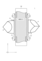
(第2の変形例)
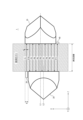
図11は、第2の変形例に係るガス測定装置3の概略構成を示す図である。第2の変形例に係るガス測定装置3は、第1の直角プリズム50と、第2の直角プリズム60と、レーザ光源30と、受光素子40とを備える。第2の変形例に係るガス測定装置3については、図3に示したガス測定装置1との相違点について主に説明し、図3に示したガス測定装置1と共通する内容については適宜説明を省略する。
(Second Modification)
Fig. 11 is a diagram showing a schematic configuration of a
第2の変形例に係るガス測定装置3は、第1のコーナーキューブ10及び第2のコーナーキューブ20の代わりに、第1の直角プリズム50及び第2の直角プリズム60を備えるという点で、図3に示したガス測定装置1と相違する。
The
第1の直角プリズム50及び第2の直角プリズム60は、直交する2つの平面を有するプリズムである。第1の直角プリズム50及び第2の直角プリズム60は、ガラスで構成されていてよい。
The first
図11は、反射回数が10回になるように、第1の直角プリズム50及び第2の直角プリズム60のX軸方向の位置が調整されている場合の概略構成を示している。
Figure 11 shows a schematic configuration in which the positions of the first
第1の直角プリズム50及び第2の直角プリズム60は、入射面がY軸方向を軸とした回転をしていても、YZ平面に平行に入射された入射光を、YZ平面に平行な方向に反射する。したがって、振動、温度などに起因する歪みなどによって、第1の直角プリズム50及び第2の直角プリズム60の入射面がY軸方向を軸とした回転方向に変動しても、その影響を受けにくいという効果を有する。
The first right-
このように、第1のコーナーキューブ10及び第2のコーナーキューブ20に比べて単純な部品であり、安価で入手性が良い部品である第1の直角プリズム50及び第2の直角プリズム60を備えるガス測定装置3であっても、振動、温度などに起因する歪みなどの物理的な変動からの影響を受けにくいという効果を有する。
Thus, even though the
なお、第1の直角プリズム50及び第2の直角プリズム60は、完全な再帰反射の特性を有さないため、様々な位置変動に対しては、図3に示したガス測定装置1の方が位置変動の影響を受けにくい。例えば、入射面がX軸方向を軸として傾いた場合、第2の変形例に係るガス測定装置3は、入射光を180度の方向に反射しないが、図3に示したガス測定装置1は、入射光を180度の方向に反射する。
The first right-
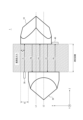
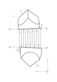
(第3の変形例)
図12、図13A及び図13Bは、第3の変形例に係るガス測定装置4の概略構成を示す図である。第3の変形例に係るガス測定装置4は、第1のコーナーキューブ10と、第2のコーナーキューブ20と、レーザ光源30と、受光素子40とを備える。
(Third Modification)
12, 13A, and 13B are diagrams showing a schematic configuration of a
図13Aは、図12の第1のコーナーキューブ10をZ軸負方向側から見た図である。図13Bは、図12の第2のコーナーキューブ20を、Z軸正方向側から見た図である。
Figure 13A shows the
第3の変形例に係るガス測定装置4については、図3に示したガス測定装置1との相違点について主に説明し、図3に示したガス測定装置1と共通する内容については適宜説明を省略する。
For the
第3の変形例に係るガス測定装置4は、レーザ光源30がY軸方向に所定の距離Cだけ中心からずらした位置に配置されているという点で、図3に示したガス測定装置1と相違する。
The
図13Aを参照すると、レーザ光源30の位置がY軸方向に中心から距離Cだけずれているため、第1のコーナーキューブ10の入射面における光路P1の位置は、Y軸方向に距離Cだけずれている。
Referring to FIG. 13A, since the position of the
X軸方向を第1の方向、Y軸方向を第2の方向、Z軸方向を第3の方向とすると、レーザ光源30は、第2の方向に中心から所定の距離だけずらした位置に配置されている。
If the X-axis direction is the first direction, the Y-axis direction is the second direction, and the Z-axis direction is the third direction, the
被測定ガス中の光路P1を通って第1のコーナーキューブ10に入射されたレーザ光は、図13Aに示すように、第1のコーナーキューブ10の中心点に対して点対称の位置で反射されて、第2のコーナーキューブ20に向けて出射される。第2のコーナーキューブ20に向けて出射されたレーザ光は、被測定ガス中の光路P2を通る。
The laser light that is incident on the
このように、レーザ光源30の位置をY軸方向に所定の距離Cだけずらすと、被測定ガス中を通過するレーザ光の光路が2列となる。これにより、被測定ガス中の広い範囲をレーザ光が通過することができるため、広い範囲のガス濃度を測定することが可能となる。
In this way, by shifting the position of the
第3の変形例に係るガス測定装置4は、所定の距離Cを調整することによって、ガス濃度を測定する範囲を調整することができる。広い範囲のガス濃度を測定したい場合は、所定の距離Cを大きくすればよい。狭い範囲のガス濃度を測定したい場合は、所定の距離Cを小さくすればよい。
The
(第4の変形例)
図14は、第4の変形例に係るガス測定装置5の概略構成を示す図である。第4の変形例に係るガス測定装置5は、第1のコーナーキューブ10と、第2のコーナーキューブ20と、レーザ光源30と、受光素子40とを備える。第4の変形例に係るガス測定装置5については、図3に示したガス測定装置1との相違点について主に説明し、図3に示したガス測定装置1と共通する内容については適宜説明を省略する。
(Fourth Modification)
Fig. 14 is a diagram showing a schematic configuration of
第4の変形例に係るガス測定装置5は、レーザ光源30が第1のコーナーキューブ10の入射面に対して斜めにレーザ光を出射するという点で、図3に示したガス測定装置1と相違する。
The
第4の変形例に係るガス測定装置5は、レーザ光源30が第1のコーナーキューブ10の入射面に対して出射するレーザ光の角度を変えることによって、反射回数を調整することができる。
The
これにより、第4の変形例に係るガス測定装置5は、第1のコーナーキューブ10及び第2のコーナーキューブ20のX軸方向の位置を変えずに、第1のコーナーキューブ10及び第2のコーナーキューブ20の位置を固定した状態で、反射回数を調整することができる。
As a result, the
図14において、破線矢印は、第1のコーナーキューブ10の入射面及び第2のコーナーキューブ20の入射面において不要反射によって発生する反射光を示す。レーザ光源30が第1のコーナーキューブ10の入射面に対して斜めにレーザ光を出射すると、図14に示すように、不要反射によるレーザ光を本来のレーザ光から分離することができる。したがって、第4の変形例に係るガス測定装置5は、不要反射による影響を低減することによって測定精度を改善することができる。
In FIG. 14, the dashed arrows indicate reflected light generated by unwanted reflections at the entrance surface of the
本開示は、その精神又はその本質的な特徴から離れることなく、上述した実施形態以外の他の所定の形態で実現できることは当業者にとって明白である。従って、先の記述は例示的であり、これに限定されない。開示の範囲は、先の記述によってではなく、付加した請求項によって定義される。あらゆる変更のうちその均等の範囲内にあるいくつかの変更は、その中に包含される。 It is obvious to those skilled in the art that the present disclosure can be realized in other specific forms than the above-described embodiments without departing from the spirit or essential characteristics thereof. Therefore, the above description is illustrative and not limiting. The scope of the disclosure is defined by the appended claims, not by the above description. Any modifications that are within the scope of the equivalents of all modifications are included therein.
例えば、上述した各構成部の配置及び個数等は、上記の説明及び図面における図示の内容に限定されない。各構成部の配置及び個数等は、その機能を実現できるのであれば、任意に構成されてもよい。 For example, the arrangement and number of each component described above are not limited to the above description and the illustrations in the drawings. The arrangement and number of each component may be configured arbitrarily as long as the function can be realized.
例えば、上述した第1の変形例~第4の変形例に示された構成は、適宜組み合わされてもよい。 For example, the configurations shown in the first to fourth modified examples described above may be combined as appropriate.
例えば、上述した実施形態において、ガス測定装置1が第1のコーナーキューブ10及び第2のコーナーキューブ20を備える構成を示したが、ガス測定装置1がレーザ光を反射するために備える光学素子はコーナーキューブに限定されない。ガス測定装置1は、再帰反射の特性を有する光学素子であれば、任意の光学素子を第1のコーナーキューブ10及び第2のコーナーキューブ20の代わりに備えていてよい。
For example, in the above embodiment, the
例えば、上述した実施形態において、第1のコーナーキューブ10及び第2のコーナーキューブ20の大きさが同じ場合を示したが、第1のコーナーキューブ10と第2のコーナーキューブ20とは異なる大きさであってよい。
For example, in the above embodiment, the
例えば、上述した実施形態において、ガス測定装置1が第1のコーナーキューブ10及び第2のコーナーキューブ20という2つのコーナーキューブを備える構成を示したが、ガス測定装置1は、3つ以上のコーナーキューブを備えていてもよい。
For example, in the above embodiment, the
例えば、上述した実施形態において、レーザ光源30と受光素子40とは、被測定ガスを挟んで反対側に配置されていたが、レーザ光源30と受光素子40とが、被測定ガスの同じ側に配置されていてもよい。レーザ光源30と受光素子40とが被測定ガスの同じ側に配置されるようにすることは、例えば、ガス測定装置1が3つのコーナーキューブを備える構成とすれば可能である。
For example, in the above-described embodiment, the
1、2、3、4、5 ガス測定装置
10 第1のコーナーキューブ
20 第2のコーナーキューブ
30 レーザ光源
40 受光素子
50 第1の直角プリズム
60 第2の直角プリズム
101 第1の凹面鏡
102 第2の凹面鏡
103 レーザ光源
104 受光素子
200 配管
210 窓ガラス
220 間隙
REFERENCE SIGNS
Claims (6)
第1のコーナーキューブ又は第1の直角プリズムと、
前記第1のコーナーキューブ又は前記第1の直角プリズムに対向して配置された第2のコーナーキューブ又は第2の直角プリズムと、
前記第1のコーナーキューブ又は前記第1の直角プリズムにレーザ光を出射するレーザ光源と、
前記第1のコーナーキューブ又は前記第1の直角プリズムと前記第2のコーナーキューブ又は前記第2の直角プリズムとの間で被測定ガスを通過して複数回反射された前記レーザ光を受光する受光素子と、
を備え、
前記第2のコーナーキューブ又は前記第2の直角プリズムは、前記第1のコーナーキューブ又は前記第1の直角プリズムの入射位置と出射位置を中心とする入出射光に平行な中心線と前記第2のコーナーキューブ又は前記第2の直角プリズムの入射位置と出射位置を中心とする入出射光に平行な中心線とがずれるように配置されている、ガス測定装置。 A gas measurement device for measuring a concentration of a gas by laser absorption spectroscopy, comprising:
a first corner cube or a first right angle prism;
a second corner cube or a second right-angle prism disposed opposite the first corner cube or the first right-angle prism;
a laser light source that emits a laser light to the first corner cube or the first right-angle prism;
a light receiving element that receives the laser light that has passed through the gas to be measured and has been reflected a plurality of times between the first corner cube or the first right-angle prism and the second corner cube or the second right-angle prism;
Equipped with
a first corner cube or a second right-angle prism is arranged so that a center line parallel to the incident and exiting light centered on the incident position and the exit position of the first corner cube or the first right-angle prism is misaligned with a center line parallel to the incident and exiting light centered on the incident position and the exit position of the second corner cube or the second right-angle prism.
前記第1のコーナーキューブ又は前記第1の直角プリズムの前記中心線と前記第2のコーナーキューブ又は前記第2の直角プリズムの前記中心線とがずれている距離によって、前記第1のコーナーキューブ又は前記第1の直角プリズムと前記第2のコーナーキューブ又は前記第2の直角プリズムとの間で前記レーザ光が反射される回数を調整可能である、ガス測定装置。 2. The gas measurement device according to claim 1,
a first right-angle prism having a center line that is offset from a center line of the second corner cube or the second right-angle prism, and a second right-angle prism having a center line that is offset from a center line of the first corner cube or the first right-angle prism, thereby adjusting the number of times the laser light is reflected between the first corner cube or the first right-angle prism and the second corner cube or the second right-angle prism.
前記第1のコーナーキューブ又は前記第1の直角プリズムの入射面、及び、前記第2のコーナーキューブ又は前記第2の直角プリズムの入射面は、前記レーザ光源が前記第1のコーナーキューブ又は前記第1の直角プリズムに前記レーザ光を出射する方向に垂直な平面に対して傾いている、ガス測定装置。 2. The gas measurement device according to claim 1,
a first corner cube or a first right-angle prism having an entrance surface, and a second corner cube or a second right-angle prism having an entrance surface, the first corner cube or a first right-angle prism having an entrance surface, the second corner cube or a second right-angle prism having an entrance surface, the second corner cube or a second right-angle prism having an entrance surface, the second corner cube or a second right-angle prism having an entrance surface,
前記第1のコーナーキューブ又は前記第1の直角プリズムの入射面、及び、前記第2のコーナーキューブ又は前記第2の直角プリズムの入射面は、内部に前記被測定ガスを有する配管に設けられた窓ガラスに密着している、ガス測定装置。 2. The gas measurement device according to claim 1,
a first corner cube having a first incident surface and a second right-angle prism having a first incident surface, and a second corner cube having a first incident surface and a second right-angle prism having a second incident surface, the first corner cube having a first incident surface and a second right-angle prism having a second incident surface, the second corner cube having a first incident surface and a second right-angle prism having a second incident surface,
前記第1のコーナーキューブ又は前記第1の直角プリズムの前記中心線と前記第2のコーナーキューブ又は前記第2の直角プリズムの前記中心線とをずらしている方向を第1の方向、前記第1のコーナーキューブ又は前記第1の直角プリズムに前記レーザ光が入射される方向を第3の方向、前記第1の方向及び前記第3の方向に直交する方向を第2の方向とすると、
前記レーザ光源は、前記第2の方向に中心から所定の距離だけずらした位置に配置されている、ガス測定装置。 2. The gas measurement device according to claim 1,
If a direction in which the center line of the first corner cube or the first right-angle prism is shifted from a center line of the second corner cube or the second right-angle prism is defined as a first direction, a direction in which the laser light is incident on the first corner cube or the first right-angle prism is defined as a third direction, and a direction perpendicular to the first direction and the third direction is defined as a second direction,
The gas measurement device, wherein the laser light source is disposed at a position shifted a predetermined distance from the center in the second direction.
前記レーザ光源は、前記第1のコーナーキューブ又は前記第1の直角プリズムの入射面に対して斜めに前記レーザ光を出射する、ガス測定装置。 2. The gas system according to claim 1,
The gas measurement device, wherein the laser light source emits the laser light obliquely with respect to an incident surface of the first corner cube or the first right-angle prism.
Priority Applications (4)
| Application Number | Priority Date | Filing Date | Title |
|---|---|---|---|
| JP2023073866A JP2024158564A (en) | 2023-04-27 | 2023-04-27 | Gas Measuring Devices |
| US18/636,780 US20240361236A1 (en) | 2023-04-27 | 2024-04-16 | Gas measurement apparatus |
| EP24170820.5A EP4455638A1 (en) | 2023-04-27 | 2024-04-17 | Gas measurement apparatus |
| CN202410464081.4A CN118858217A (en) | 2023-04-27 | 2024-04-17 | Gas measuring device |
Applications Claiming Priority (1)
| Application Number | Priority Date | Filing Date | Title |
|---|---|---|---|
| JP2023073866A JP2024158564A (en) | 2023-04-27 | 2023-04-27 | Gas Measuring Devices |
Publications (1)
| Publication Number | Publication Date |
|---|---|
| JP2024158564A true JP2024158564A (en) | 2024-11-08 |
Family
ID=90789622
Family Applications (1)
| Application Number | Title | Priority Date | Filing Date |
|---|---|---|---|
| JP2023073866A Pending JP2024158564A (en) | 2023-04-27 | 2023-04-27 | Gas Measuring Devices |
Country Status (4)
| Country | Link |
|---|---|
| US (1) | US20240361236A1 (en) |
| EP (1) | EP4455638A1 (en) |
| JP (1) | JP2024158564A (en) |
| CN (1) | CN118858217A (en) |
Citations (10)
| Publication number | Priority date | Publication date | Assignee | Title |
|---|---|---|---|---|
| JPS5342878A (en) * | 1976-09-30 | 1978-04-18 | Wako Kk | Soot concentration measuring apparatus |
| JPS57153239U (en) * | 1981-03-24 | 1982-09-25 | ||
| JPH02249955A (en) * | 1989-03-24 | 1990-10-05 | Hirama Rika Kenkyusho:Kk | Multiple times reflected light type absorptiometry |
| JP2008026229A (en) * | 2006-07-24 | 2008-02-07 | Shimadzu Corp | Reflective optical device |
| CN203894137U (en) * | 2014-05-30 | 2014-10-22 | 江苏师范大学 | Detection system for aerosol employing extinction method |
| CN105445196A (en) * | 2014-12-17 | 2016-03-30 | 邓文平 | Sample measuring cell |
| US20170146451A1 (en) * | 2015-11-25 | 2017-05-25 | Unisearch Associates Inc. | Gas cell for absorption spectroscopy |
| CN107941751A (en) * | 2017-12-28 | 2018-04-20 | 南京科远自动化集团股份有限公司 | The laser sensing method and laser sensor arrangements of a kind of high temperature process furnances |
| CN108507959A (en) * | 2018-06-01 | 2018-09-07 | 济南盛泰电子科技有限公司 | A kind of variable light path gas absorption gas chamber sensor-based system |
| CN111537453A (en) * | 2020-04-23 | 2020-08-14 | 山东省科学院激光研究所 | A two-dimensional multi-point reflection long optical path gas sensor probe and gas sensor |
-
2023
- 2023-04-27 JP JP2023073866A patent/JP2024158564A/en active Pending
-
2024
- 2024-04-16 US US18/636,780 patent/US20240361236A1/en active Pending
- 2024-04-17 CN CN202410464081.4A patent/CN118858217A/en active Pending
- 2024-04-17 EP EP24170820.5A patent/EP4455638A1/en active Pending
Patent Citations (12)
| Publication number | Priority date | Publication date | Assignee | Title |
|---|---|---|---|---|
| JPS5342878A (en) * | 1976-09-30 | 1978-04-18 | Wako Kk | Soot concentration measuring apparatus |
| JPS57153239U (en) * | 1981-03-24 | 1982-09-25 | ||
| JPH02249955A (en) * | 1989-03-24 | 1990-10-05 | Hirama Rika Kenkyusho:Kk | Multiple times reflected light type absorptiometry |
| JP2008026229A (en) * | 2006-07-24 | 2008-02-07 | Shimadzu Corp | Reflective optical device |
| CN203894137U (en) * | 2014-05-30 | 2014-10-22 | 江苏师范大学 | Detection system for aerosol employing extinction method |
| CN105445196A (en) * | 2014-12-17 | 2016-03-30 | 邓文平 | Sample measuring cell |
| US20180113065A1 (en) * | 2014-12-17 | 2018-04-26 | Suzhou Taospec Optronics Co., Ltd. | Sample measurement pool |
| US20170146451A1 (en) * | 2015-11-25 | 2017-05-25 | Unisearch Associates Inc. | Gas cell for absorption spectroscopy |
| CN107941751A (en) * | 2017-12-28 | 2018-04-20 | 南京科远自动化集团股份有限公司 | The laser sensing method and laser sensor arrangements of a kind of high temperature process furnances |
| CN108507959A (en) * | 2018-06-01 | 2018-09-07 | 济南盛泰电子科技有限公司 | A kind of variable light path gas absorption gas chamber sensor-based system |
| CN111537453A (en) * | 2020-04-23 | 2020-08-14 | 山东省科学院激光研究所 | A two-dimensional multi-point reflection long optical path gas sensor probe and gas sensor |
| US20230324281A1 (en) * | 2020-04-23 | 2023-10-12 | Laser Institute, Shandong Academy Of Sciences | Two-dimensional multi-point-reflection long-optical-path gas sensor probe and gas sensor |
Also Published As
| Publication number | Publication date |
|---|---|
| CN118858217A (en) | 2024-10-29 |
| US20240361236A1 (en) | 2024-10-31 |
| EP4455638A1 (en) | 2024-10-30 |
Similar Documents
| Publication | Publication Date | Title |
|---|---|---|
| CN107941477B (en) | Spectroscope measurement method and device capable of accurately controlling incident angle | |
| JP6657059B2 (en) | Multiple reflection type cell, analyzer, exhaust gas analyzer, and light incident method | |
| JP2000206035A (en) | Gas detecting apparatus | |
| US11994619B2 (en) | Light irradiation apparatus and laser radar apparatus | |
| JP4823289B2 (en) | Reflective scatterometer | |
| CN104011516B (en) | Laser output determinator | |
| KR20220079977A (en) | Concentration measuring method and concentration measuring device | |
| CN110514139A (en) | A kind of the reflecting mirror surface shape change detecting device and method of laser interferometry system | |
| JP2022124718A (en) | Multi-reflection apparatus and multi-reflection cell | |
| US7760361B2 (en) | Surface plasmon detection using curved surface prism and reflecting member | |
| KR102700310B1 (en) | Concentration measuring device | |
| JP2024158564A (en) | Gas Measuring Devices | |
| CN115144366A (en) | Gas analyzer | |
| JP2009515159A (en) | Laser radiation source | |
| EP1853897B1 (en) | Gas cell using two parabolic concave mirrors and method of producing gas sensor using the same | |
| CN118837894A (en) | Edge detection sensor | |
| CN105737758A (en) | Long trace profile | |
| CN116482036A (en) | Compact and highly sensitive gas detector | |
| CN108872099B (en) | Method for accurately measuring concentration of hydrogen sulfide gas by detector | |
| CN222013318U (en) | Three-wavelength Raman test probe | |
| CN119986957B (en) | An automatic focusing system and thickness measurement system suitable for semi-transparent wafers | |
| US12517059B2 (en) | Optical device | |
| CN116660165B (en) | Long-optical-path optical gas absorption cell and gas sensor | |
| CN111780721B (en) | Laser beam splitter grid line perpendicularity detection device and detection method | |
| JP2002139425A (en) | Photodetector for calibration |
Legal Events
| Date | Code | Title | Description |
|---|---|---|---|
| A621 | Written request for application examination |
Free format text: JAPANESE INTERMEDIATE CODE: A621 Effective date: 20250509 |
|
| A977 | Report on retrieval |
Free format text: JAPANESE INTERMEDIATE CODE: A971007 Effective date: 20251208 |
|
| A131 | Notification of reasons for refusal |
Free format text: JAPANESE INTERMEDIATE CODE: A131 Effective date: 20260203 |
|
| A521 | Request for written amendment filed |
Free format text: JAPANESE INTERMEDIATE CODE: A523 Effective date: 20260401 |