JP2024148564A - Magnifying glasses or telescopes - Google Patents
Magnifying glasses or telescopes Download PDFInfo
- Publication number
- JP2024148564A JP2024148564A JP2023061787A JP2023061787A JP2024148564A JP 2024148564 A JP2024148564 A JP 2024148564A JP 2023061787 A JP2023061787 A JP 2023061787A JP 2023061787 A JP2023061787 A JP 2023061787A JP 2024148564 A JP2024148564 A JP 2024148564A
- Authority
- JP
- Japan
- Prior art keywords
- telescope
- magnifying glass
- section
- nose pad
- front frame
- Prior art date
- Legal status (The legal status is an assumption and is not a legal conclusion. Google has not performed a legal analysis and makes no representation as to the accuracy of the status listed.)
- Pending
Links
Images

Landscapes
- Telescopes (AREA)
Abstract
Description
本発明は、使用者が顔に装着するメガネ型のメガネ部と、該メガネ部に取り付けられて支持された拡大鏡部又は望遠鏡部とを備えるメガネ型の拡大鏡又は望遠鏡に関する。 The present invention relates to a glasses-type magnifying glass or telescope that includes a glasses-type glasses section that is worn on the face of the user, and a magnifying glass section or telescope section that is attached to and supported by the glasses section.
従来、使用者が顔に装着するメガネ型のメガネ部と、該メガネ部に取り付けられて支持された拡大鏡部又は望遠鏡部とを備えるメガネ型の拡大鏡又は望遠鏡がある。このようなメガネ型の拡大鏡又は望遠鏡の一例として、例えば特許文献1、2に示すように、外科医などが手術の際に対象物を拡大して見るために使用する医療用ルーペがある。この医療用ルーペには、メガネの枠(フレーム)に直接的に、あるいは左右レンズを介して間接的に一対のルーペを取り付けたタイプのものがある。
Conventionally, there are eyeglass-type magnifying glasses or telescopes that include an eyeglass-type eyeglass part that the user wears on the face, and a magnifying glass part or telescope part that is attached to and supported by the eyeglass part. One example of such eyeglass-type magnifying glasses or telescopes is a medical loupe that is used by surgeons and others to magnify and view objects during surgery, as shown in
このような医療用ルーペは、使用者がメガネをかけることで顔に装着し、その状態で左右レンズの前面側にある左右ルーペの接眼部を覗き込むことで対象物を拡大して見ることができる。しかしながら、左右ルーペは重量があるため、このルーペ付めがねを着用すると、めがねの重量を支えるため鼻に圧迫感が生ずる。またルーペの重量により、ツル部(テンプル)と、これに挟まれた耳の上の頭部とがずれて、メガネが前のめりになりやすく、ルーペで対象物を観察するために首を上向きに修正する必要が生じ、疲労感が生じやすい。 When wearing these medical loupes, the user can place them on their face while wearing their glasses, and look through the eyepieces of the loupes located on the front side of the left and right lenses to magnify and view the object. However, because the loupes are heavy, wearing these glasses with loupes creates a feeling of pressure on the nose as they support the weight of the glasses. In addition, the weight of the loupes can cause the temples to shift from the head above the ears that are sandwiched between them, making the glasses prone to leaning forward, and requiring the user to tilt their neck upward to observe the object through the loupes, which can easily cause fatigue.
本発明は上述の点に鑑みてなされたものであり、その目的は、着用時の重量感・疲労感を低減することができるメガネ型の拡大鏡又は望遠鏡を提供することにある。 The present invention has been made in consideration of the above points, and its purpose is to provide a glasses-type magnifying glass or telescope that reduces the sense of weight and fatigue when worn.
上記課題を解決するため、本発明にかかるメガネ型の拡大鏡又は望遠鏡は、使用者が顔に装着するメガネ部(10)と、対象物を拡大又は望遠観察可能な拡大鏡部又は望遠鏡部(30)と、拡大鏡部又は望遠鏡部(30)を、メガネ部(10)の前面側に配置する使用位置と、メガネ部(10)の上方に跳ね上げる退避位置との間で移動可能に保持する連結部(20)と、を備えるメガネ型の拡大鏡又は望遠鏡(1,1-2,1-3)であって、メガネ部(10)は、前フレーム(16)と、前フレーム(16)の両サイドにヒンジ部(17a,17b)を介して連結された一対のツル部(18a、18b)と、前フレーム(16)の中央に取付けられて、使用者の鼻に載置される鼻当て部(19)と、を備えるフレーム(11)と、前フレーム(16)に取り付けられた左右レンズ(12a,12b)と、を備え、鼻当て部(19)は、頂部が前フレーム(16)に固定されて斜めに伸びる左右アーム部を有する略逆V字型の鼻当てフレーム(19-1)と、左右アーム部を覆うとともに該左右アーム部の中間部同士を橋渡す鼻当てカバー(19-2)からなり、各ヒンジ部(17a,17b)は、ツル部(18a、18b)がクッション材(17d)を挟んで当接する開き角限界ストッパ(17c)を有し、連結部(20)は、使用位置における拡大鏡部又は望遠鏡部(30)の光軸方向が、左右レンズ(12a,12b)の光軸方向に対して1~5度上向きになるように拡大鏡部又は望遠鏡部(30)を保持する。 In order to solve the above problems, the eyeglass-type magnifying glass or telescope of the present invention is an eyeglass-type magnifying glass or telescope (1, 1-2, 1-3) comprising an eyeglass section (10) worn by the user on the face, a magnifying glass section or telescope section (30) that allows the user to magnify or telescope-view an object, and a connecting section (20) that movably holds the magnifying glass section or telescope section (30) between a use position where the magnifying glass section or telescope section (30) is disposed on the front side of the eyeglass section (10) and a retracted position where the magnifying glass section or telescope section (30) is flipped up above the eyeglass section (10), and the eyeglass section (10) comprises a front frame (16), a pair of temple sections (18a, 18b) connected to both sides of the front frame (16) via hinge sections (17a, 17b), and a nose pad section (19) attached to the center of the front frame (16) and placed on the user's nose. The glasses have a frame (11) and left and right lenses (12a, 12b) attached to the front frame (16). The nose pads (19) are made up of an inverted V-shaped nose pad frame (19-1) with left and right arms that extend diagonally and have their tops fixed to the front frame (16), and a nose pad cover (19-2) that covers the left and right arms and bridges the middle parts of the left and right arms. Each hinge (17a, 17b) has an opening angle limit stopper (17c) that the temples (18a, 18b) abut against with cushioning material (17d) sandwiched between them. The connecting part (20) holds the magnifying glass or telescope part (30) so that the optical axis of the magnifying glass or telescope part (30) in the usage position is 1 to 5 degrees upward relative to the optical axis of the left and right lenses (12a, 12b).
本発明にかかるメガネ型の拡大鏡又は望遠鏡によれば、鼻当て部(19)を、略逆V字型の鼻当てフレーム(19-1)と、鼻当てフレームの左右アーム部を覆うとともに該左右アーム部の中間部同士を橋渡す鼻当てカバー(19-2)とで構成したので、鼻の左右斜面に接触する左右アーム部と鼻の稜線に接触する橋渡し部分に荷重点が分散でき、またカバーによりクッション性が向上して、重量感が低減できる。また、前フレーム(16)と各ツル部(18a,18b)とを接続するヒンジ部(17a,17b)は、ツル部がクッション材(17d)を挟んで当接する開き角限界ストッパ(17c)を有するので、クッション材の分だけ左右のツル部の開き角が抑制されるとともに、顔幅とツル部間隔との間に差異があってもクッション材の適度な力でツルが頭部の両側面に良好に密着するので、ツルによって拡大鏡部又は望遠鏡部の重さを効果的に支持することができ、めがねが前のめりになるのを良好に防ぐことができる。また、連結部(20)は、使用位置における拡大鏡部又は望遠鏡部(30)の光軸(AX2)方向が、左右レンズ(12a,12b)の光軸(AX1)方向に対して1~5度上向きになるように拡大鏡部又は望遠鏡部(30)を保持する構成にしたので、拡大鏡部又は望遠鏡部(30)の重量でメガネ型の拡大鏡又は望遠鏡が僅かに前のめりになっても、対象物を視認でき、首の疲労感が低減できる。 In the eyeglass-type magnifying glass or telescope of the present invention, the nose pad section (19) is composed of a nose pad frame (19-1) that is substantially inverted V-shaped, and a nose pad cover (19-2) that covers the left and right arm sections of the nose pad frame and bridges the middle sections of the left and right arm sections. This allows the load points to be distributed between the left and right arm sections that come into contact with the left and right slopes of the nose, and the bridging section that comes into contact with the nasal ridge, and the cover improves cushioning and reduces the feeling of weight. Furthermore, the hinge sections (17a, 17b) connecting the front frame (16) and each temple section (18a, 18b) have opening angle limit stoppers (17c) where the temple sections abut through the cushioning material (17d), so that the opening angle of the left and right temple sections is restricted by the amount of the cushioning material, and even if there is a difference between the face width and the temple spacing, the moderate force of the cushioning material allows the temples to adhere well to both sides of the head, so that the weight of the magnifying glass section or telescope section can be effectively supported by the temples, and the glasses can be effectively prevented from leaning forward. In addition, the connecting portion (20) is configured to hold the magnifying glass or telescope portion (30) so that the optical axis (AX2) of the magnifying glass or telescope portion (30) in the usage position is 1 to 5 degrees upward relative to the optical axis (AX1) of the left and right lenses (12a, 12b). This means that even if the weight of the magnifying glass or telescope portion (30) causes the eyeglass-type magnifying glass or telescope to lean forward slightly, the object can still be seen and neck fatigue can be reduced.
特に、本発明にかかるメガネ型の拡大鏡又は望遠鏡では、上記の鼻当て部(19)及び鼻当てカバー(19-2)の構成と、ヒンジ部(17a,17b)が備える角限界ストッパ(17c)の構成と、使用位置における拡大鏡部又は望遠鏡部(30)の光軸(AX2)方向を上向きにした構成との3つの構成を同時に備えることによって、メガネ型の拡大鏡又は望遠鏡の重心位置の最適化を図ることで、拡大鏡部又は望遠鏡部(30)の重さでメガネ型の拡大鏡又は望遠鏡が前のめりになることを効果的に防止している。すなわち、これら3つの構成を同時に備えることで、拡大鏡部又は望遠鏡部(30)を備えることによるメガネ型の拡大鏡又は望遠鏡の重量感を効果的に低減して軽快なかけ心地を実現可能としている。 In particular, the eyeglass-type magnifying glass or telescope of the present invention has three configurations at the same time: the configuration of the nose pad portion (19) and nose pad cover (19-2), the configuration of the angle limit stopper (17c) of the hinge portion (17a, 17b), and the configuration in which the optical axis (AX2) of the magnifying glass portion or telescope portion (30) is oriented upward in the use position. This optimizes the position of the center of gravity of the eyeglass-type magnifying glass or telescope, thereby effectively preventing the eyeglass-type magnifying glass or telescope from leaning forward due to the weight of the magnifying glass portion or telescope portion (30). In other words, by having these three configurations at the same time, the weight of the eyeglass-type magnifying glass or telescope due to the magnifying glass portion or telescope portion (30) is effectively reduced, making it possible to achieve a light and comfortable fit.
また、このメガネ型の拡大鏡又は望遠鏡では、鼻当てカバー(19-2)は、革製で、鼻当てフレームの左右アーム部をそれぞれ覆う左右鞘筒状部分(19-2a,19-2b)と該左右鞘状部分同士を連結する橋渡し部分(19-2c)からなり、鼻当てフレーム(19-1)は、柔軟性を有して略U型形状に弾性変型可能であるものであってよい。 In addition, in this eyeglass-type magnifying glass or telescope, the nose pad cover (19-2) is made of leather and consists of left and right sheath tubular parts (19-2a, 19-2b) that respectively cover the left and right arm parts of the nose pad frame, and a bridge part (19-2c) that connects the left and right sheath parts, and the nose pad frame (19-1) may be flexible and elastically deformable into an approximately U-shape.
この構成によれば、鼻当てフレームを略U型形状に弾性変形させて略平行になった左右アーム部分を、鼻当てカバー左右の鞘状部分をそれぞれ挿入させてから、鼻当てフレームを元の略V型に復帰させることによりに、鼻当てカバーを容易に装着でき、かつ位置ずれや脱落を起しにくいというメリットがある。 This configuration has the advantage that the nose pad frame is elastically deformed into a roughly U-shape, the left and right arm sections are made roughly parallel, the left and right sheath-like sections of the nose pad cover are inserted into them, and then the nose pad frame is returned to its original roughly V-shape, making it easy to attach the nose pad cover and less likely to shift out of place or fall off.
また、このメガネ型の拡大鏡又は望遠鏡では、鼻当てカバー(19-2)は、中央のくびれ部分(50c)とその左右に連続する略矩形または略半円形の左右部分(50a,50b)からなる略亜鈴型の革製シート(50)を用い、当該シートの左右部分(50a,50b)の、左右軸を挟んで対向する辺同士を、左右軸回りに折り曲げて縫い合わせて裏返すことにより、左右鞘状部分(19-2a,19-2b)を形成し、くびれ部分(50c)を橋渡し部分(19-2c)としてもよい。 In addition, in this eyeglass-type magnifying glass or telescope, the nose pad cover (19-2) is made of a roughly dumbbell-shaped leather sheet (50) consisting of a central waisted portion (50c) and roughly rectangular or roughly semicircular left and right portions (50a, 50b) continuing to the left and right of the central waisted portion (50c), and the left and right sheath-like portions (19-2a, 19-2b) are formed by folding the opposing sides of the left and right portions (50a, 50b) of the sheet about the left and right axis, sewing them together, and turning them inside out, with the waisted portion (50c) serving as the bridging portion (19-2c).
この構成によれば、革製の鼻当てカバーを容易に形成でき、裏返すことにより、縫い目部分内側になって鼻に当たらず、快適な装着性が得られる。 This configuration makes it easy to form a leather nose pad cover, and by turning it inside out, the seam is on the inside and does not touch the nose, making it comfortable to wear.
また、このメガネ型の拡大鏡又は望遠鏡では、クッション材(17d)は、ゴムシートであってもよい。 In addition, in this eyeglass-type magnifying glass or telescope, the cushioning material (17d) may be a rubber sheet.
この構成によれば、市販の様々な厚さのゴムシートを利用できるので、ツル部の自然状態での開き角や、所定の開き角での挟持力を容易に調整できる。 This configuration allows the use of commercially available rubber sheets of various thicknesses, making it easy to adjust the opening angle of the temples in their natural state and the clamping force at a specified opening angle.
また、このメガネ型の拡大鏡又は望遠鏡では、連結部は、前フレームに固定された基部(21)と、該基部に設けられてあおり方向に回動可能なヒンジ部(22)と、該ヒンジ部に回動可能に枢支されるとともに拡大鏡部又は望遠鏡部(30)を支持する支持アーム(23)を含み、基部(21)の前フレーム(16)に対する取り付けを上方向に1~5度傾かせたものであってもよい。 In addition, in this eyeglass-type magnifying glass or telescope, the connecting part includes a base part (21) fixed to the front frame, a hinge part (22) provided on the base part and rotatable in the tilt direction, and a support arm (23) rotatably supported on the hinge part and supporting the magnifying glass part or telescope part (30), and the attachment of the base part (21) to the front frame (16) may be tilted upward by 1 to 5 degrees.
この構成により、使用位置における拡大鏡部又は望遠鏡部(30)の光軸(AX2)方向が、左右レンズ(12a,12b)の光軸(AX1)方向に対して1~5度上向きになる構成を実現できる。なお、ここでいう「取り付けを上方向に1~5度傾かせる」とは、例えば、前フレーム(16)の取り付け面又は基部(21)の取り付け面の一部を削るか、薄い箔などを挟むことにより基部(21)の前フレーム(16)に対する取付角度を調整して行うことができる。
This configuration allows the optical axis (AX2) of the magnifying glass or telescope section (30) in the use position to be oriented 1 to 5 degrees upward relative to the optical axis (AX1) of the left and right lenses (12a, 12b). Note that "tilting the
また、このメガネ型の拡大鏡又は望遠鏡では、左右レンズ(12a,12b)における少なくとも左右拡大鏡又は望遠鏡の接眼部(36a,36b)の周囲の位置を覆うシート材(40a,40b)をさらに備える、ものであってもよい。このシート材は、左右レンズ(12a,12b)の表面に貼付しても良く、接眼部(36a,36b)に装着していても良い。 The eyeglass-type magnifying glass or telescope may further include a sheet material (40a, 40b) that covers at least the area around the eyepieces (36a, 36b) of the left and right lenses (12a, 12b). This sheet material may be attached to the surfaces of the left and right lenses (12a, 12b) or may be attached to the eyepieces (36a, 36b).
この構成によれば、左右拡大鏡又は望遠鏡の接眼部を覗き込む際に周辺の景色が視界に入らないので、対象物の観察に神経を集中でき、前述した疲労感低減効果と相俟って疲労感をさらに低減できる。なお、上記の括弧内の符号は、後述する実施形態の対応する構成要素の符号を本発明の一例として示したものである。 With this configuration, when looking through the eyepiece of the left/right magnifying glass or telescope, the surrounding scenery is not visible, allowing the user to concentrate on observing the object, which, combined with the fatigue reduction effect described above, further reduces fatigue. Note that the reference numerals in parentheses above are examples of the present invention and correspond to the reference numerals of the corresponding components in the embodiments described below.
本発明にかかるメガネ型の拡大鏡又は望遠鏡によれば、着用時の重量感・疲労感を低減することができる。 The eyeglass-type magnifying glass or telescope of the present invention can reduce the sense of weight and fatigue felt when worn.
以下、添付図面を参照して本発明の実施形態を詳細に説明する。下記の第一乃至第三実施形態の説明では、本発明にかかるメガネ型の拡大鏡又は望遠鏡の実施形態として、医療用のルーペ(メガネ型の拡大鏡)を例に説明をするが、本発明はこの実施形態に限られるものではなく、メガネ型の望遠鏡にも適用が可能である。
〔第一実施形態〕
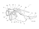
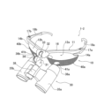
図1は、本発明にかかるメガネ型の拡大鏡又は望遠鏡の第一実施形態である医療用ルーペ(メガネ型の拡大鏡)を示す斜視図である。図1に示す医療用ルーペ1は、使用者が顔に装着するメガネ部10と、対象物を拡大観察するルーペ部(本発明の拡大鏡部又は望遠鏡部)30と、ルーペ部30をその使用位置と退避位置との間で移動可能に保持する連結部20とを備えて構成されている。
Hereinafter, the embodiments of the present invention will be described in detail with reference to the accompanying drawings. In the following description of the first to third embodiments, a medical loupe (magnifying glass in the form of glasses) will be described as an example of the embodiment of the magnifying glass in the form of glasses or telescope according to the present invention, but the present invention is not limited to this embodiment and can also be applied to a telescope in the form of glasses.
First Embodiment
Fig. 1 is a perspective view showing a medical loupe (a magnifying glass in the form of glasses) which is a first embodiment of a magnifying glass or telescope in the form of glasses according to the present invention. The
メガネ部10は、フレーム11に左レンズ12aと右レンズ12bが取り付けられてメガネ型に形成されている。フレーム11は、通常の合成樹脂製のメガネフレームと同様、前フレーム16と、前フレーム16の両サイドにヒンジ部17a,17bを介して折り畳み可能に連結された一対のツル部18a,18bと、前フレーム16の中央に取付けられた鼻当て部19を備えている。前フレーム16の下辺の左右それぞれに形成した溝部(図示せず)に左レンズ12aと右レンズ12bとが嵌め込まれて取り付けられている。
The
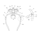
図2(a)はツル部18a,18bを開いた状態の医療用ルーペ1の平面図で、メガネ部10、連結部20、ルーペ部30のそれぞれ一部の構成要素を示している。図2(b)は右側のツル部18bを折りたたんだ状態のA部(ヒンジ部17b)の機能を示す拡大図である。ヒンジ部17bは、ツル部18bがクッション材17dを挟んで当接する開き角限界ストッパ17cを有する。本実施形態では、クッション材17dは、ゴムシートを用いている。詳細な図示は省略するが、左側のヒンジ部17aも構造は同じである。
Figure 2(a) is a plan view of the
この構成によれば、クッション材17dの厚さ分だけ左右のツル部18a,18bの開き角が抑制されるとともに、顔幅とツル部18a,18b間隔との間に差異があってもクッション材17dの適度な力でツル部18a,18bが頭部の左右側面(耳の上の部分の側面)に押し当てられた状態で良好に密着(当接)するので、ツル部18a,18bの当該密着部を支点としてルーペ部30の重さを支えることが可能となる。したがって、ツル部18a,18bにより、メガネが前のめりになるのを良好に防ぐことができる。また、クッション材17dとして市販の様々な厚さのゴムシートを利用できるので、ツル部18a,18bの自然状態での開き角や、所定の開き角での挟持力を容易に調整できる。なお、本実施形態では、クッション材17dをツル部18a,18b側に設けて、開き角限界ストッパ17cへの当接時にクッション材17dが挟まる構成にしたが、クッション材17dを開き角限界ストッパ17c側に設けてもよい。
With this configuration, the opening angle of the left and
鼻当て部19は、図3に示すように、鼻当てフレーム19-1と鼻当てカバー19-2から構成されている。鼻当てフレーム19-1は、頂部19-1cが前フレーム16に固定されて斜めに伸びる左右アーム部19-1a,19-1bを有する略逆V字型を有する。この鼻当てフレーム19-1は、柔軟性を有する素材で構成され、略U型形状に弾性変型可能である。鼻当てカバー19-2は、革材で構成され、鼻当てフレーム19-1の左右アーム部19-1a,19-1bをそれぞれ覆う左右鞘状部分19-2a,19-2bとこれらを連結する橋渡し部分19-2cからなる。
As shown in Figure 3, the
この構成により、左右鞘状部分19-2a,19-2bを介して鼻の左右斜面に接触する左右アーム部19-1a,19-1bと鼻の稜線に接触する橋渡し部分19-2cに荷重点が分散でき、また鼻当てカバー19-2によりクッション性が向上して、重量感が低減できる。また、この構成によれば、鼻当てフレーム19-1を略U型形状に弾性変形させて略平行になった左右アーム部19-1a,19-1bを、鼻当てカバー19-2の左右鞘状部分19-2a,19-2bをそれぞれ挿入させてから、鼻当てフレーム19-1を元の略V型に復帰させることによりに、鼻当てカバー19-2を容易に装着でき、かつ位置ずれや脱落を起しにくいというメリットがある。尚、図3には、左右レンズ12a,12bを通して見える後述する左右ルーペ35a,35bも示している。また、本実施形態では、図3の前フレーム16の中央にはネームプレート16-1が取り付けられている。このネームプレート16-1は、板状の部材を前フレーム16の中央にボルト16-2の締結などで固定したものである。このネームプレート16-1には、使用者の名前やイニシャルなど好きな文字を入れたネーム16-3を記載できる。ネーム16-3は刻印又は印刷のどちらでもよい。そして、このネームプレート16-1は、環境対策の一環として、他のメガネフレームを制作した際の端材を削ったものを使用することが可能である。ネームプレート16-1には、図示は省略するが、刻印や印刷により文字やロゴなどを入れることが可能である。また、左右レンズ12a,12bにも使用者の名前やイニシャルなど好きな文字を入れたネーム12-1を刻印又は印刷等で入れることができる。
This configuration distributes the load to the left and right arm parts 19-1a, 19-1b that contact the left and right slopes of the nose via the left and right sheath parts 19-2a, 19-2b, and the bridge part 19-2c that contacts the nasal ridge, and the nose pad cover 19-2 improves cushioning and reduces the sense of weight. This configuration also has the advantage that the nose pad cover 19-2 can be easily attached and is less likely to shift or fall off by inserting the left and right arm parts 19-1a, 19-1b, which are approximately parallel to each other after the nose pad frame 19-1 is elastically deformed into an approximately U-shape, into the left and right sheath parts 19-2a, 19-2b of the nose pad cover 19-2, respectively, and then restoring the nose pad frame 19-1 to its original approximately V-shape. Note that Figure 3 also shows the left and
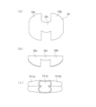
図4に本実施形態の鼻当てカバー19-2の製作方法を示す。図4(a)は、鼻当てカバー19-2の素材となる裁断した革製シート50を示す平面図で、この革製シート50は、中央のくびれ部分50cとその左右に連続する略矩形または略半円形の左右部分50a,50bからなる略亜鈴型を有する。図4(b)は、この革製シート50の左右部分50a,50bの、左右軸を挟んで対向する辺同士を、左右軸回りに折り曲げて縫い合わせた状態を示す側面図である。この破線は縫製線を示す。図4(c)は、縫い合わせた左右部分50a,50bの革材の表裏を裏返すことにより、左右鞘状部分19-2a,19-2bを形成した状態を示す。このとき、くびれ部分50cにより橋渡し部分19-2cが形成されている。この構成によれば、革製の鼻当てカバー19-2を容易に形成でき、裏返すことにより、縫い目部分が内側になって鼻に当たらず、快適な装着性が得られる。
Figure 4 shows a method for manufacturing the nose pad cover 19-2 of this embodiment. Figure 4(a) is a plan view showing a
次に、図1に戻ってルーペ部30と連結部20について説明する。
ルーペ部30は、対象物を拡大観察するユニットで、左ルーペ35aと右ルーペ35bと、これらをその間隔調整可能に保持する保持部38と、左右間隔調整ノブ39とを供えている。この左右間隔調整ノブ39を回転させることで、左ルーペ35aと右ルーペ35bの間隔を調節可能に構成されている。
Next, returning to FIG. 1, the magnifying
The
連結部20は、本実施形態では、前フレーム16に固定された基部21と、該基部21に設けられてあおり方向に回動可能なヒンジ部22と、該ヒンジ部22に回動可能に枢支された支持アーム23と、該支持アーム23上に設けられ、ルーペ部30を支持アーム23の軸方向にスライド可能に保持するスライド機構24と、該スライド機構24の可動側に設けられた左右のハンドル25a,25bと、を含む。なお、基部21は、詳細には前フレームの中央の前面(左レンズ12aと右レンズ12bの間の部分の前面)に固定されている。
この構成により、左右のハンドル25a,25bを掴んでルーペ部30をヒンジ部22回りに回動させることで、メガネ部10の前面側に配置する使用位置とメガネ部10の上方に跳ね上げる退避位置との間で移動可能になっている。また、使用位置において、左右のハンドル25a,25bを掴んでルーペ部30をスライド機構24に沿って前後方向に動かすことでも可能である。
In this embodiment, the connecting
With this configuration, by gripping the left and
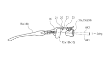
ここで、図5に示すように、連結部20は、使用位置におけるルーペ部30の光軸AX2方向が、左レンズ12aと右レンズ12bの光軸AX1方向に対して1~5度上向きになるようにルーペ部30を保持する構成にした。本実施形態では、基部21の前フレーム16に対する取り付けを上方向に1~5度傾かせることにより、この構成を実現している。ここでいう「基部21の前フレーム16に対する取り付けを上方向に傾かせる」とは、例えば、詳細な図示は省略するが、基部21の前後方向の中心軸がツル部18a,18bの中心軸に対して前側が上になるように上向きに傾いている状態、あるいは、それによってアーム23の中心軸がツル部18a,18bの中心軸に対して前側が上になるように上向きに傾いている状態などであってよい。あるいは、使用者が医療用ルーペ1を装着した状態で、基部21の根元側(フレーム側)の上端面よりも前側(ヒンジ側)の上端面の方が上方に突出している状態であってもよい。そして、この「基部21の前フレーム16に対する取り付けを上方向に傾かせる」という構成は、例えば、前フレーム16又は基部21の取り付け面の一部(具体的には上側の一部)を削るか、あるいは、取り付け面の一部(具体的には下側の一部)に薄い箔などを挟むことにより取付面を横から見て斜めに傾かせた状態とすることによって実現できる。若しくは、図示しないが、連結部20のヒンジ部22に、回動下限ストッパを設け、このストッパの位置を調整して、支持アーム23の下限角度を調整することにより、使用位置におけるルーペ部30の光軸AX2方向を、左レンズ12aと右レンズ12bの光軸AX1方向に対して1~5度上向きとなるようにしてもよい。この構成により、ルーペ部30の重量で医療用ルーペ1が僅かに前のめりになっても、対象物を視認でき、首の疲労感が低減できる。
5, the connecting
〔第二実施形態〕
次に、本発明の第二実施形態について説明する。なお、第2実施形態の説明及び対応する図面においては、第一実施形態と同一又は相当する構成部分には同一の符号を付し、以下ではその部分の詳細な説明は省略する。また、以下で説明する事項以外の事項、及び図示する以外の事項については、第一実施形態と同じである。この点は、下記の他の実施形態についても同様である。なお、後述する図6及び図7において、アーム部31、基部32、第1ヒンジ部33は、第一実施形態の連結部20、基部21、ヒンジ部22(図1参照)にそれぞれ相当する。アーム部31は、第一実施形態の連結部20と比較すると、スライド機構24の代わりに第2ヒンジ部34を有し、また左右ルーペ35a,35bの保持部38も異なるが、このような構成にも本発明は適用できる。
Second Embodiment
Next, a second embodiment of the present invention will be described. In the description of the second embodiment and the corresponding drawings, the same reference numerals are used for the components that are the same as or equivalent to those in the first embodiment, and detailed description of those components will be omitted below. In addition, matters other than those described below and those not shown in the drawings are the same as those in the first embodiment. This also applies to the other embodiments described below. In addition, in Figs. 6 and 7 described later, the
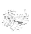
図6は、本発明にかかるメガネ型の拡大鏡又は望遠鏡の第二実施形態である医療用ルーペ1-2を示す図である。本実施形態の医療用ルーペ1-2は、左ルーペ35aの接眼部36a及びその周辺に対応する位置の左レンズ12aの表面に貼付したシート材(左シート材)40aと、右ルーペ35bの接眼部36b及びその周辺に対応する位置の右レンズ12bの表面に貼付したシート材(右シート材)40bとを備えている。左右シート材40a,40bは、左右レンズ12a,12bそれぞれの略下半分の部分のみに貼付されており、左右レンズ12a,12bの左右シート材40a,40bが貼付されていない上半分の部分は、透明で視認性が確保された非貼付部14a,14bになっている。左右シート材40a,40bは、表裏面が黒色で非光沢のシート材であり、左右レンズ12a,12bの略下半分の全体を覆う外形を有し、かつ、左右ルーペ35a,35bの接眼部36a,36bに対応する部分には円形の開口部からなる覗き穴41a,41bが形成されている。
Figure 6 is a diagram showing a medical loupe 1-2, which is a second embodiment of the eyeglass-type magnifying glass or telescope according to the present invention. The medical loupe 1-2 of this embodiment comprises a sheet material (left sheet material) 40a attached to the surface of the
本実施形態の医療用ルーペ1-2は、使用者がメガネ部10のツル部18a,18bを耳に掛けることでメガネのように顔に装着する。その状態で、上記の退避位置にあるルーペ部30を下向きに回動させて左右レンズ12a,12bの前に降ろすことで上記の使用位置とする。これにより、使用者が左右シート材40a,40bの覗き穴41a,41bを介して左右ルーペ35a,35bの接眼部36a,36bを覗くことができ、ルーペ部30で対象物を拡大して見ることができる。このとき、覗き穴41a,41b及び左右ルーペ35a,35bの接眼部36a,36bの周囲が左右シート材40a,40bで覆われていることで、左右ルーペ35a,35bの接眼部36a,36bを覗き込む際に周辺の景色が視界に入らずに済む。したがって、左右ルーペ35a,35bで見る対象物に神経を集中することができ、手術などの作業の効率を格段に向上させることができる。
The medical loupe 1-2 of this embodiment is worn on the face like glasses by the user placing the
その一方で、左右シート材40a,40bは、左右レンズ12a,12bの略下半分のみに貼付されているため、左右レンズ12a,12bの略上半分(非貼付部14a,14b)は視界が確保された状態である。そのため、手術などの作業をしている使用者は、医療用ルーペ1を装着したままの状態で視線を上に向けるだけで、手術室のモニター画面や他の作業者の顔などを見ることができる。したがって、ルーペ部30を通した対象物の視認性の向上を図りながらも、対象物以外の周囲の確認を容易かつ確実に行うことができる。
On the other hand, the left and
また、本実施形態の医療用ルーペ1-2では、ルーペ部30を上方に跳ね上げて退避位置とすれば、左右ルーペ35a,35bを通さずに対象物を直接見ることができる。すなわち、左右シート材40a,40bに覗き穴41a,41bが設けられているので、この覗き穴41a,41bを介して対象物を見ることができるので、対象物をルーペ部30を介さずに直接確認することもできる。
In addition, in the medical loupe 1-2 of this embodiment, if the
なお、本実施形態の医療用ルーペ1-2では、左右レンズ12a,12bには度数の無いレンズを用いるが、これ以外にも、左右シート材40a,40bの覗き穴41a,41bに対応する部分に度数を入れたレンズを用いるようにしてもよい。この場合、覗き穴41a,41bに対応する部分は視野が拡大されるような度数を入れるようにする。これにより、ルーペ部30を退避位置とした状態でも覗き穴41a,41bを通して見る対象物がある程度拡大されて見えるので、細かい物を見易くなるという効果がある。また、ルーペ部30を介して対象物を見る場合にも、左右レンズ12a,12bの度数とルーペ部30(左右ルーペ35a,35b)の度数を合わせた度数で対象物を拡大して見ることができるので、簡単な構成でより高倍率の拡大率が得られるという効果もある。
In the medical loupe 1-2 of this embodiment, lenses without power are used for the left and
〔第三実施形態〕
次に、本発明の第三実施形態について説明する。図7は、本発明にかかるメガネ型の拡大鏡又は望遠鏡の第三実施形態である医療用ルーペ1-3を示す図である。第二実施形態の医療用ルーペ1-2では、左右シート材40a,40bが左右レンズ12a,12bの表面に貼付されていたのに対して、本実施形態の医療用ルーペ1-3が備える左右シート材40a,40bは、左右レンズ12a,12bの表面ではなく、左右ルーペ35a,35bの接眼部36a,36bに取り付けられている。
Third Embodiment
Next, a third embodiment of the present invention will be described. Fig. 7 is a diagram showing a medical loupe 1-3, which is a third embodiment of the eyeglass-type magnifying glass or telescope according to the present invention. In the medical loupe 1-2 of the second embodiment, the left and
左右シート材40a,40bは、左右レンズ12a,12bの略下半分の前面を覆う外形を有し、かつ左右ルーペ35a,35bの接眼部36a,36bに対応する部分に円形の開口部からなる覗き穴41a,41bが設けられている。その状態で、左右ルーペ35a、35bの接眼部36a,36bに一体に取り付け(貼り付け)られている。したがって、左右シート材40a,40bは、ルーペ部30と一体に上下に移動(回動)する。
The left and
本実施形態の医療用ルーペ1-3は、第一実施形態の医療用ルーペ1-2と同様、使用者がメガネ部10のツル部18a,18bを耳に掛けることでメガネのように顔に装着する。その状態で退避位置にあるルーペ部30を下向きに回動させて左右レンズ12a,12bの前に降ろすことで使用位置とする。これにより、左右シート材40a,40bが左右レンズ12a,12b(詳細には左右レンズ12a,12bの略下半分)の前に配置され、左右ルーペ35a,35bの接眼部36a,36bの周囲が覆われた状態となる。したがって、医療用ルーペ1と同様、左右ルーペ35a,35bの接眼部36a,36bの周囲が左右シート材40a,40bで覆われていることで、左右ルーペ35a,35bの接眼部36a,36bを覗き込む際に周辺の景色が視界に入らずに済む。したがって、左右ルーペ35a,35bで見る対象物に神経を集中することができ、手術などの作業の効率を格段に向上させることができる。
The medical loupe 1-3 of this embodiment is worn on the face like glasses by the user placing the
なお、本実施形態の医療用ルーペ1-3では、左右シート材40a,40bが左右レンズ12a,12bの前に配置されたときに、左右シート材40a,40bを左右レンズ12a,12bの前面に係止するための係止片42a,42bを備えている。係止片42a,42bは、左右シート材40a,40bの外周縁から左右レンズ12a,12b側に向かって延びる弾性を有する細片状の部分であってよい。係止片42a,42bは、左右シート材40a,40bが左右レンズ12a,12bの前に配置されたときに弾性変形することで、左右レンズ12a,12bの縁を乗り越えてその裏面側(顔側)に引っ掛かるように構成されている。したがって、この係止片42a、42bを備えることで、左右シート材40a,40bを左右レンズ12a,12bの前面に正確に位置決めされた状態で配置できるようになる。これにより、左右ルーペ35a,35bの接眼部36a,36bを覗き込む際により確実に周辺の景色が視界に入らずに済むようになる。
In addition, the medical loupe 1-3 of this embodiment is provided with locking
以上、本発明の実施形態を説明したが、本発明は、上記実施形態に限定されるものではなく、特許請求の範囲、及び明細書と図面に記載された技術的思想の範囲内において種々の変形が可能である。例えば、上記第1の実施形態では、メガネ部10とルーペ部30を連結する連結部20にヒンジ機構を採用したが、代わりにボールジョイント機構を用いてもよい。
Although the embodiments of the present invention have been described above, the present invention is not limited to the above embodiments, and various modifications are possible within the scope of the claims and the technical ideas described in the specification and drawings. For example, in the first embodiment, a hinge mechanism is used for the connecting
また、第一実施形態の医療用ルーペ1では、左右レンズ12a,12bには度数の無いレンズを用いるが、これ以外にも、度数を入れたレンズを用いるようにしてもよい。
In addition, in the
また、上記第一乃至第三実施形態では、本発明にかかるメガネ型の拡大鏡又は望遠鏡の実施形態として、メガネ型の拡大鏡である医療用ルーペを例に説明したが、本発明はこの実施形態に限定されるものではなく、遠方の対象物を拡大して見るためのオペラグラスや双眼鏡として使用することが可能なメガネ型の望遠鏡であってもよい。その場合、メガネ部に左右望遠鏡を有する望遠鏡部を取り付けた構成となる。またその場合、上記第一乃至第三実施形態の医療用ルーペを例に説明した本発明の鼻当て部、ツル部支持のヒンジ機構及び、使用位置における拡大鏡又は望遠鏡の光軸角度に関する構成は、そのままメガネ型の望遠鏡に適用することができる。 In addition, in the above first to third embodiments, a medical loupe, which is a glasses-type magnifying glass, has been described as an example of an embodiment of the glasses-type magnifying glass or telescope of the present invention, but the present invention is not limited to this embodiment, and the glasses-type telescope may be used as opera glasses or binoculars for magnifying and viewing distant objects. In that case, a telescope unit having left and right telescopes is attached to the glasses unit. In that case, the nose pads, the hinge mechanism for supporting the temples, and the configuration related to the optical axis angle of the magnifying glass or telescope in the use position of the present invention described as an example of the medical loupes of the above first to third embodiments can be applied directly to the glasses-type telescope.
また、上記実施形態の医療用ルーペ1~1-3では、メガネ部10の左右レンズ12a,12bの前面それぞれに左ルーペ35aと右ルーペ35bを配置した双眼鏡型のルーペである場合を説明したが、本発明にかかるメガネ型の拡大鏡又は望遠鏡は、これ以外にも、左右レンズのいずれか一方の前面のみに拡大鏡又は望遠鏡を配置した単眼鏡型であってもよい。
In addition, in the above embodiment of
1,1-2,1-3 医療用ルーペ
10 メガネ部
11 フレーム
12a,12b 左右レンズ
14a,14b 非貼付部
12-1 ネーム
16 前フレーム
16-1 ネームプレート
16-2 ボルト
16-3 ネーム
17a,17b ヒンジ部
17c 開き角限界ストッパ
17d クッション材
18a,18b ツル部
19 鼻当て部
19-1 鼻当てフレーム
19-1c 頂部
19-1a,19-1b 左右アーム部
19-2 鼻当てカバー
19-2a,19-2b 左右鞘状部分
19-2c 橋渡し部分
20 連結部
21 基部
22 ヒンジ部
23 支持アーム
24 スライド機構
25a,25b 左右のハンドル
30 ルーペ部(本発明の拡大鏡部又は望遠鏡部)
31 アーム部
32 基部
33 第一ヒンジ部
34 第2ヒンジ部
35a,35b 左右ルーペ
36a,36b 接眼部
38 保持部
39 左右間隔調整ノブ
40a,40b 左右シート材
41a,41b 覗き穴
42a,42b 係止片
50 革製シート
50a,50b 左右部分
50c くびれ部分
AX1 (左右レンズ)の光軸
AX2 (ルーペ部30の)光軸
1, 1-2, 1-3
31
35a, 35b Left and right magnifying glasses
36a, 36b Eyepiece
38
Claims (6)
前記メガネ部は、前フレームと、前記前フレームの両サイドにヒンジ部を介して連結された一対のツル部と、前記前フレームの中央に取付けられて、使用者の鼻に載置される鼻当て部と、を備えるフレームと、
前記前フレームに取り付けられた左右レンズと、を備え、
前記鼻当て部は、頂部が前記前フレームに固定されて斜めに伸びる左右アーム部を有する略逆V字型の鼻当てフレームと、前記左右アーム部を覆うとともに該左右アーム部の中間部同士を橋渡す鼻当てカバーからなり
各前記ヒンジ部は、前記ツル部がクッション材を挟んで当接する開き角限界ストッパを有し、
前記連結部は、前記使用位置における前記拡大鏡部又は望遠鏡部の光軸方向が、前記左右レンズの光軸方向に対して1~5度上向きになるように前記拡大鏡部又は望遠鏡部を保持する、メガネ型の拡大鏡又は望遠鏡。 A glasses-type magnifying glass or telescope comprising: a glasses section that a user wears on the face; a magnifying glass section or telescope section that allows the user to magnify or telescope-view an object; and a connecting section that movably holds the magnifying glass section or telescope section between a use position where the magnifying glass section or telescope section is disposed on the front side of the glasses section and a retracted position where the glasses section is flipped up above the glasses section;
The eyeglasses part includes a frame including a front frame, a pair of temple parts connected to both sides of the front frame via hinge parts, and a nose pad part attached to the center of the front frame and placed on the user's nose;
Left and right lenses attached to the front frame;
The nose pads are comprised of a generally inverted V-shaped nose pad frame having left and right arm portions each extending obliquely with its top fixed to the front frame, and a nose pad cover that covers the left and right arm portions and bridges between the middle portions of the left and right arm portions. Each of the hinge portions has an opening angle limit stopper that the temple portion abuts against with a cushioning material sandwiched therebetween.
The connecting portion holds the magnifying glass portion or telescope portion so that the optical axis direction of the magnifying glass portion or telescope portion in the usage position is oriented upward by 1 to 5 degrees relative to the optical axis directions of the left and right lenses.
Priority Applications (1)
| Application Number | Priority Date | Filing Date | Title |
|---|---|---|---|
| JP2023061787A JP2024148564A (en) | 2023-04-05 | 2023-04-05 | Magnifying glasses or telescopes |
Applications Claiming Priority (1)
| Application Number | Priority Date | Filing Date | Title |
|---|---|---|---|
| JP2023061787A JP2024148564A (en) | 2023-04-05 | 2023-04-05 | Magnifying glasses or telescopes |
Publications (1)
| Publication Number | Publication Date |
|---|---|
| JP2024148564A true JP2024148564A (en) | 2024-10-18 |
Family
ID=93062385
Family Applications (1)
| Application Number | Title | Priority Date | Filing Date |
|---|---|---|---|
| JP2023061787A Pending JP2024148564A (en) | 2023-04-05 | 2023-04-05 | Magnifying glasses or telescopes |
Country Status (1)
| Country | Link |
|---|---|
| JP (1) | JP2024148564A (en) |
-
2023
- 2023-04-05 JP JP2023061787A patent/JP2024148564A/en active Pending
Similar Documents
| Publication | Publication Date | Title |
|---|---|---|
| US11650433B2 (en) | Visual loupes with point of view modification | |
| US11061257B1 (en) | Visual loupes with point of view modification | |
| JP5212901B2 (en) | Glasses-type image display device | |
| US4886340A (en) | Optical device for precision work | |
| JP2010231119A (en) | Glasses-type image display device | |
| JP2017218696A (en) | Lens body mounting mechanism | |
| US20020093622A1 (en) | Flip-up eyewear | |
| JPWO2017126583A1 (en) | Head mounted display | |
| JP3885072B2 (en) | Eyeglass frame and lens hanger | |
| MXPA01007456A (en) | Makeup eyeglasses. | |
| KR20190049869A (en) | A pair of perspective frames | |
| JP7491012B2 (en) | Head-Mounted Display | |
| JP7242241B2 (en) | head mounted device | |
| JP2024148564A (en) | Magnifying glasses or telescopes | |
| WO2007148650A1 (en) | Spectacles set | |
| JP4626072B2 (en) | Video observation device | |
| US11940671B2 (en) | Spectacle-like frame | |
| WO2020003622A1 (en) | Head mounted display | |
| JP7199094B2 (en) | Overglass | |
| GB2251702A (en) | Spectacles attachment | |
| JP3210521U (en) | Additional glasses for clear vision | |
| JPH07261128A (en) | Bifocal spectacles | |
| TWI727158B (en) | Spectacle-like frame | |
| CN110073278B (en) | glasses-shaped simple frame | |
| JP6651120B2 (en) | Surgical magnifier |
Legal Events
| Date | Code | Title | Description |
|---|---|---|---|
| A621 | Written request for application examination |
Free format text: JAPANESE INTERMEDIATE CODE: A621 Effective date: 20260401 |