JP2024136102A - Steel pipe threaded joint and manufacturing method thereof - Google Patents
Steel pipe threaded joint and manufacturing method thereof Download PDFInfo
- Publication number
- JP2024136102A JP2024136102A JP2023047079A JP2023047079A JP2024136102A JP 2024136102 A JP2024136102 A JP 2024136102A JP 2023047079 A JP2023047079 A JP 2023047079A JP 2023047079 A JP2023047079 A JP 2023047079A JP 2024136102 A JP2024136102 A JP 2024136102A
- Authority
- JP
- Japan
- Prior art keywords
- pin
- steel pipe
- thread
- threaded joint
- taper angle
- Prior art date
- Legal status (The legal status is an assumption and is not a legal conclusion. Google has not performed a legal analysis and makes no representation as to the accuracy of the status listed.)
- Pending
Links
Images



Landscapes
- Piles And Underground Anchors (AREA)
- Non-Disconnectible Joints And Screw-Threaded Joints (AREA)
Abstract
Description
本発明は、鋼管ねじ継手および鋼管ねじ継手の製造方法に関する。 The present invention relates to a steel pipe threaded joint and a method for manufacturing a steel pipe threaded joint.
従来、軟弱地盤でのトンネル掘削時には、崩落防止を目的としてAGF工法(All Ground Fasten、長尺鋼管先受け工法)が用いられている。このようなAGF工法では、トンネルの切羽の断面に例えば外径76.3mm~114.3mmの鋼管が12.5mの深さで複数本打ち込まれることが多い。この場合、鋼管が1本当たり約3mの長さで通称ドリルジャンボと呼ばれる掘削機上で管端に加工されたねじ継手を人力によって1杭当り3箇所を締結し、掘削しながら全長12.5mに仕上げていく。 Traditionally, when excavating tunnels in soft ground, the AGF method (All Ground Fasten, a long steel pipe fore-supporting method) has been used to prevent collapse. With this type of AGF method, multiple steel pipes, for example with outer diameters of 76.3 mm to 114.3 mm, are often driven into the cross section of the tunnel face to a depth of 12.5 m. In this case, the steel pipes are about 3 m long each, and threaded joints machined into the ends of the pipes on an excavator commonly known as a drill jumbo are tightened manually at three points per pile, and the total length is completed to 12.5 m while excavating.
上述したような従来の杭用鋼管の接合では、コストと施工しやすさの観点から切削ねじ継手が使用されている(例えば、特許文献1、2参照)。
切削ねじ継手として、例えば図9(a)~(c)に示す種類のねじ継手100A、100B、100C等が知られている。
In conventional joining of steel pipes for piles as described above, cut threaded joints have been used from the viewpoints of cost and ease of construction (see, for example,
Known examples of cut threaded joints include threaded
図9(a)に示す第1ねじ継手100Aは、厚肉鋼管に予め、雄ねじ101を刻設したピン104と、雌ねじ102を刻設したボックス105と、のそれぞれを杭本体103に溶接、摩擦圧接、拡散接合等で一体化し螺合する形態のものである。図9(b)に示す第2ねじ継手100Bは、杭本体103に雌ねじ102を刻設したボックス106に両端に雄ねじを刻設したニップル107で螺合する形態のものである。図9(c)に示す第3ねじ継手100Cは、杭本体103には予備加工せずに管端に直接、雄ねじ101を刻設したピン104と雌ねじ102を刻設したボックス105とを螺合する形態のものである。
また、他のねじ継手の形態として鋼管外径側に張り出すカップリングタイプもあるが、地盤に打ち込む際の抵抗となるため好ましくない。
The first threaded
Another type of threaded joint is the coupling type, which protrudes outward toward the outer diameter of the steel pipe, but this is not preferred because it creates resistance when driving the joint into the ground.
しかしながら、従来の鋼管ねじ継手では、以下のような問題があった。
すなわち、従来の鋼管ねじ継手のうち前述した図9(a)に示す第1ねじ継手100Aでは、製造コストの観点から予め加工したねじ部を溶接などで一体化するには継手素管を供給し、溶接にかかる費用が増大するという問題があった。図9(b)に示す第2ねじ継手100Bの場合には、ニップル107等の接合部品を用いるために継手素管を供給し、杭1箇所の接合に対して2組の雄ねじ、雌ねじを加工する必要があることから、コストが増大することになる。また、図9(c)に示す第3ねじ継手100Cの場合には、製造コストの観点から上記の第1ねじ継手100Aや第2ねじ継手100Bに比べて望ましいが、鋼管が薄肉化すると継手の引張強度確保が困難になるという問題があった。
However, conventional steel pipe threaded joints have the following problems.
That is, in the first threaded
さらに、トンネル工法では、材質STK400の鋼管が用いられてきたが、肉厚5mm~6mm程度で長さ3m当りの重量が最大で50kg程度に及び、さらに鋼管単体ではなくドリルビットやビットに動力を伝えるシャフトの重量を含めた3mの部材として取り扱われるため、部材1本当たりの重量は50kgを超える場合も考えられる。上述したドリルジャンボの掘削機上において一人で50kgを超える部材を挿入したり締結するにはかなりの労力が必要となることから、安全面、効率面からも鋼管の軽量化、及びねじ継手の締結しやすさが求められている。 Furthermore, in tunnel construction methods, steel pipes made of STK400 material have been used, but with a wall thickness of about 5mm to 6mm, they weigh up to about 50kg per 3m length, and because they are handled as a 3m component including the weight of the drill bit and the shaft that transmits power to the bit, rather than as a single steel pipe, the weight of each component can exceed 50kg. Since it requires a considerable amount of effort for one person to insert and fasten a component weighing more than 50kg on the drill jumbo excavator mentioned above, there is a demand for lighter steel pipes and easier fastening of threaded joints from the standpoints of safety and efficiency.
本発明は、上述する問題点に鑑みてなされたもので、薄肉化および高強度化することで本体部の軽量化を図ることができ、鋼管の引張強度を高めることができる鋼管ねじ継手および鋼管ねじ継手の製造方法を提供することを目的とする。 The present invention was made in consideration of the above-mentioned problems, and aims to provide a steel pipe threaded joint and a method for manufacturing a steel pipe threaded joint that can reduce the weight of the main body by making it thinner and stronger, and can increase the tensile strength of the steel pipe.
(1)本発明に係る鋼管ねじ継手の態様1は、建設分野の工事において地盤に打ち込む鋼管同士をねじ込むことによって締結するための鋼管ねじ継手であって、一方の前記鋼管の外面に雄ねじが形成されたピンと、他方の前記鋼管の内面に前記ピンの前記雄ねじに螺合可能な雌ねじが形成されたボックスと、を有し、前記ピンと前記ボックスのねじ列は、前記鋼管の管軸に対して第1テーパー角度で傾斜したねじ列テーパー部が形成され、前記ピンの最小内径は、前記鋼管のうち前記ピンと前記ボックスとを除く本体部の鋼管内径より小さく、前記ピンは、前記雄ねじの完全ねじ部終端から前記本体部にかけて第2テーパー角度だけ傾斜したピン連設部を有し、前記第2テーパー角度は、前記第1テーパー角度の2倍以下であることを特徴としている。
(1)
本発明に係る鋼管ねじ継手によれば、一方の鋼管の管端を縮径し、直接加工した雄ねじを刻設したピンと、他方の鋼管の管端に雌ねじを刻設したボックスを螺合するねじ構造において、双方の鋼管の外径を一致させた状態で、ピンの最小内径を本体部の鋼管内径より小さくするとともに、ピン連設部の第2テーパー角度が第1テーパー角度の2倍以下とすることで、鋼管内の内空断面積を施工に支障なく確保することができ、引張強度の低下を抑えつつ、同外径のまま薄肉化することができる。そのため、本発明の鋼管ねじ継手では、従来の鋼管継手部に比べて鋼管の引張強度が高めることができ、従来の鋼管と同等の引張強度でも薄肉化が可能となり鋼管の軽量化を図ることができる。
このように本発明では、鋼管が薄肉で軽量化されることから、鋼管を手で持って締め込む作業を軽減することができ、作業の効率化を図ることができる。そして、この場合には、鋼管の引張強度を確保できることから、地盤への鋼管の打設間隔等を変更させることなく打設することができる。
According to the steel pipe threaded joint of the present invention, in a thread structure in which a pin having a male thread machined directly on the end of one steel pipe is screwed into a box having a female thread machined on the end of the other steel pipe, the outer diameters of both steel pipes are matched, and the minimum inner diameter of the pin is made smaller than the inner diameter of the steel pipe of the main body, and the second taper angle of the pin connecting portion is set to be equal to or less than twice the first taper angle, so that the inner hollow cross-sectional area of the steel pipe can be secured without hindrance to construction, and the steel pipe can be thinned while maintaining the same outer diameter while suppressing a decrease in tensile strength. Therefore, with the steel pipe threaded joint of the present invention, the tensile strength of the steel pipe can be increased compared to conventional steel pipe joints, and the steel pipe can be thinned even with the same tensile strength as conventional steel pipes, thereby reducing the weight of the steel pipe.
In this way, the present invention reduces the work of manually tightening the steel pipes because the steel pipes are thin-walled and lightweight, and improves the efficiency of the work. In this case, the tensile strength of the steel pipes can be ensured, so that the steel pipes can be driven into the ground without changing the driving intervals, etc.
(2)本発明の態様2は、態様1の鋼管ねじ継手において、前記ピンの最小内径は、前記鋼管同士を締結した状態で、前記本体部の前記鋼管内径に対して80%以上であることが好ましい。
(2) In
この場合には、鋼管同士を締結した状態で、ピンの最小内径を本体部の鋼管内径に対して80%以上に制限することで、鋼管内において掘削用ドリルやモルタル注入管等の通過を概ね許容できる。そのため、ピンが上記範囲において鋼管の内径側へ張り出していても、従来の鋼管内での作業を支障なく行うことが可能な鋼管内断面積を確保することができる。 In this case, by limiting the minimum inner diameter of the pin to 80% or more of the inner diameter of the main steel pipe when the steel pipes are fastened together, it is possible to generally allow the passage of excavation drills, mortar injection pipes, etc., inside the steel pipe. Therefore, even if the pin protrudes into the inner diameter of the steel pipe within the above range, it is possible to ensure a cross-sectional area inside the steel pipe that allows conventional work inside the steel pipe to be carried out without hindrance.
(3)本発明に係る鋼管ねじ継手の製造方法の態様3は、態様1又は態様2の鋼管ねじ継手を製造するための鋼管ねじ継手の製造方法において、前記鋼管の一端に前記雌ねじを含む前記ボックスを加工する工程と、前記鋼管の一端の直径を縮小する縮径加工を行う工程と、前記縮径加工を行った後に縮径した部分に前記雄ねじを含む前記ピンを加工する工程と、を有することを特徴とする。
(3)
本発明に係る鋼管ねじ継手の製造方法によれば、上述した構成の鋼管ねじ継手において、雄ねじおよび雌ねじの精度を確保することができ、ピンのねじ列テーパー部およびピン連設部を効率よく加工することができる。 According to the manufacturing method of the steel pipe threaded joint of the present invention, the precision of the male and female threads can be ensured in the steel pipe threaded joint having the above-mentioned configuration, and the thread row taper portion and the pin connecting portion of the pin can be efficiently machined.
本発明の鋼管ねじ継手および鋼管ねじ継手の製造方法によれば、薄肉化および高強度化することで本体部の軽量化を図ることができ、鋼管の引張強度を高めることができる。 The steel pipe threaded joint and manufacturing method for the steel pipe threaded joint of the present invention can reduce the weight of the main body by making it thinner and increasing its strength, and can increase the tensile strength of the steel pipe.
以下、本発明の実施形態による鋼管ねじ継手および鋼管ねじ継手の製造方法について、図面に基づいて説明する。 Below, a steel pipe threaded joint and a method for manufacturing a steel pipe threaded joint according to an embodiment of the present invention will be described with reference to the drawings.
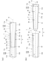
図1に示すように、本実施形態による鋼管ねじ継手1は、建設分野の工事において、管端に対して直接、ねじを加工したテーパーねじ継手であり、2本の鋼管10(10A、10B)同士をねじ込むことによって管軸方向に締結するためのものである。
As shown in FIG. 1, the steel pipe threaded
鋼管10A、10Bは、管体表面に凹凸のないストレート管であって、例えば外径76.3mm、肉厚2.6mmの短尺鋼管(例えば、長さ3m程度)に適用している。鋼管10A、10Bを本実施形態の鋼管ねじ継手1によって管軸方向に締結される土木用鋼管は、例えばAGF工法等でトンネル若しくは斜面等の地盤を補強するための地盤補強用鋼管(例えば、トンネルの鏡ボルト又は長尺フォアパイル等) として用いられる。
The
また、本実施形態の鋼管ねじ継手1を用いて連結される鋼管10A、10Bは、建造物の基礎杭など、他の用途の鋼管杭として用いられてもよい。鋼管10A、10Bとして、例えば、一般構造用炭素鋼鋼管、建築構造用炭素鋼鋼管などを用いることができる。
The
鋼管ねじ継手1は、図1(a)、(b)の紙面右側の一方の鋼管(第1鋼管10A)の外面に雄ねじ2Aが加工されたピン2と、紙面左側の他方の鋼管(第2鋼管10B)の内面にピン2の雄ねじ2Aに螺合可能な雌ねじ3Aが加工されたボックス3と、を有している。ピン2の雄ねじ2Aとボックス3の雌ねじ3Aが完全に連結した状態では、雄ねじ2Aと雌ねじ3Aが密着して螺合し、ピン2とボックス3が安定的に締結される。雄ねじ2Aと雌ねじ3Aは、相互に隙間無く嵌合するように対称な凹凸形状となっている。なお、鋼管10において、ピン2とボックス3とを除く部分を以下、本体部11A、11Bという。
The steel pipe threaded
ここで、以下の説明では、ピン2及びボックス3において、それぞれが形成される鋼管10A、10Bの中心軸(管軸O)方向に沿う方向を管軸方向と定義する。そして、ピン2及びボックス3における管軸方向Xで端部側を管端側、管端側と反対側で本体部11A、11B側を基端側と定義する。また、管軸Oに直交する方向を径方向と定義し、管軸方向Xから見て管軸O回りに周回する方向周方向と定義する。そして、径方向で管軸Oを向く側を内径側、内径側の反対側で管軸Oから離れる方向を外径側と定義する。また、管軸Oに平行な仮想軸線を符号O1で示す。
In the following description, the direction along the central axis (pipe axis O) of the
ピン2とボックス3のねじ列は、それぞれ鋼管10A、10Bの管軸Oに対してねじ列テーパー角度θ1(第1テーパー角度)で傾斜したねじ列テーパー部21、31が形成されている。図面においてねじ列テーパー角度θ1は、管軸Oに平行な仮想軸線O1とピンねじ列テーパー部21とがなす角度、および仮想軸線O1とボックスねじ列逆テーパー部31とがなす角度である。
The thread rows of the
ピン2のピンねじ列テーパー部21は、第1鋼管10Aの一方の端部側の外面において、管軸方向Xで基端側から管端側に向かうに従い漸次、管軸Oに近づいて縮径されるテーパーに雄ねじ2Aを形成している。
ボックス3のボックスねじ列逆テーパー部31は、第2鋼管10Bの一方の端部側の内面において、管軸方向Xで基端側から管端側に向かうに従い漸次、管軸Oから離れて拡径されるテーパーに雌ねじ3Aを形成している。
The pin thread
The box thread row
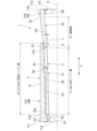
ピン2は、図2に示すように、ピン先端2aからピン基端2b(第1鋼管10Aのピン本体部11A側)に向けた順で、ピンねじ列テーパー部21と、雄ねじ2Aの雄ねじ終端21aとピン本体部11Aの外周面11aとを連設するピン連設部22と、を備えている。
As shown in FIG. 2, the
ボックス3は、ボックスねじ列逆テーパー部31と、ボックスねじ列逆テーパー部31の基端側に配置されるショルダー部32と、を備えている。ボックス3は、ショルダー部32を介してボックス本体部11Bの内周面11dに連設している。
The
鋼管10A、10Bは、ピン2の雄ねじ2Aとボックス3の雌ねじ3Aとの螺合によって締結した状態で、ピン先端2aとボックス3の雌ねじ終端31aとが径方向に対向するとともに、ボックス先端3aとピン2の雄ねじ終端21aとが径方向に対向する。
When the
ボックス3のショルダー部32は、管軸Oにほぼ垂直な環状面32aと、ボックス本体部11Bのボックス3側の内周面11dと、から構成されている。ショルダー部32の環状面32aとピン先端2aとの間には、鋼管10A、10B同士が締結された状態でわずかな隙間が形成されている。ショルダー部32は、ボックス3に対するピン2の乗り上げを規制するストッパの機能を有している。また、ショルダー部32にピン2との間に隙間を設けることで、鋼管10の削孔時の振動により鋼管10同士がさらに締め込み可能な許容領域となり、鋼管10A、10B同士をより強固に締結することができる。
The
ピン2の雄ねじ2Aとボックス3の雌ねじ3Aは、ピンねじ列テーパー部21及びボックスねじ列逆テーパー部31において同一のねじピッチ、ねじ高さ、ねじ列テーパー角度θ1で相互に嵌合(螺合)する。鋼管ねじ継手1においては、ピン2を回転させながらボックス3内に挿入して、ピン2の雄ねじ2Aとボックス3の雌ねじ3Aを十分に螺合させることにより、図1(a)に示すように、ピン2とボックス3が締結されて、2本の鋼管10A、10Bを管軸方向Xに連結できる。雄ねじ2Aと雌ねじ3Aとにより螺合される継手部分の厚み寸法は、各本体部11A、11Bの厚さより大きい。そのため、鋼管10A、10B同士を締結した状態では、上述したように継手部分のピン2がピン本体部11Aの内径側に張り出している。
The
図1(b)、図2および図3に示すように、ピン2の最小内径D1は、ピン本体部11Aの鋼管内径D2より小さい。すなわち、ピン2は、ピン本体部11Aの内周面11bより内径側に張り出している。ピン2の最小内径D1は、鋼管10A、10B同士を締結した状態で、ピン本体部11Aの鋼管内径D2に対して80%以上であり、より好ましくは90%以上に設定される。
As shown in Figures 1(b), 2 and 3, the minimum inner diameter D1 of the
ここで、土木工事に使用される杭や鋼管の内部には、掘削用ドリルやモルタル注入管など様々なものが通過するため、継手部(ピン2)がピン本体部11Aの内周面11bから内径側に張り出す量を抑制する必要がある。工事の種類によって張り出し量の上限は様々だが、ピン本体部11Aの鋼管内径D2に対してピン2の最小内径D1を80%以上に設定することで、掘削用ドリルやモルタル注入管等の通過を許容できる。
Since various objects such as drills and mortar injection pipes pass through the inside of piles and steel pipes used in civil engineering works, it is necessary to limit the amount by which the joint part (pin 2) protrudes from the inner
また、とくにトンネル補強工事に外径76.3mm、肉厚2.0mm程度(内径72.3mm程度)の薄肉鋼管を適用することを想定すると、ピン2の最小内径D1を現在使用されている現行鋼管(外径76.3mm、肉厚5.2mm)の内径65.9mmよりも大きくすれば、新規の工具や器具を準備せずに現在使用されている工具や器具をそのまま使用できることから、ピン2の最小内径D1をピン本体部11Aの鋼管内径D2に対して90%以上(現行鋼管の内径65.9mmと薄肉鋼管の内径72.3mmの比率が約91%)とすることがより好ましい。
In particular, assuming that thin-walled steel pipes with an outer diameter of 76.3 mm and a thickness of approximately 2.0 mm (inner diameter of approximately 72.3 mm) will be used in tunnel reinforcement work, if the minimum inner diameter D1 of
また、図3に示すように、ピン2は、雄ねじ2Aの雄ねじ終端21aからピン本体部11Aにかけて設けられるピン連設部22はピンテーパー角度θ2(第2テーパー角度)だけ傾斜している。図3においてピンテーパー角度θ2は、管軸Oに平行な仮想軸線O1とピン連設部22とがなす角度である。
このとき、ピンテーパー角度θ2は、ねじ列テーパー角度θ1の2倍以下(テーパー比率θ2/θ1≦2)に設定されている。ピン連設部22は、雄ねじ終端21a側の外周面に、ねじ加工時において切削工具を鋼管外径側に逃がすための継手逃がし部23が形成されている。
3, the
At this time, the pin taper angle θ2 is set to be equal to or less than twice the thread row taper angle θ1 (taper ratio θ2/θ1≦2). The
図3に示すように、ピン連設部22におけるピンテーパー角度θ2は、ねじ列テーパー角度θ1の2倍以下とすることで、継手逃がし部23の最小肉厚tを危険断面Sに対して90%以上にすることが可能となる。すなわち、継手の危険断面Sに対して継手逃がし部23の肉厚が薄くなることによる継手の引張強度の低下を抑制するためには、危険断面Sに対して10%程度の薄肉の許容分を考慮して、ピンテーパー角度θ2をねじ列テーパー角度θ1の2倍以下に設定することが好ましい。
As shown in FIG. 3, by setting the pin taper angle θ2 in the pin-connected
なお、ピンテーパー角度θ2は、小さくなるにつれてピン連設部22の厚さは厚くなるため、継手引張強度の観点ではθ2の下限値は存在しない。一方で、ピン2の内径よりピン連設部22が内側に張り出している場合、鋼管内径を通過するシャフトなどの工具が干渉する可能性があり、θ2は0より大きいことが好ましい。すなわちテーパー比率θ2/θ1のより望ましい範囲は0<θ2/θ1≦2となる。
In addition, as the pin taper angle θ2 becomes smaller, the thickness of the
さらに詳細に説明する。素管によく用いられる一般構造用鋼管(JIS G3444)には肉厚公差として-12.5%~+15%が設定されており、素管部で肉厚は最大-12.5%まで不可避的に薄くなる。すなわち、その分、引張強度が低下する可能性があることを考慮すると、継手逃がし部23の最小肉厚tも危険断面Sに対して10%程度薄肉になることは許容できる。
Let me explain in more detail. General structural steel pipes (JIS G3444) that are often used for base pipes have a wall thickness tolerance of -12.5% to +15%, and the wall thickness of the base pipe is inevitably thinned to a maximum of -12.5%. In other words, considering that the tensile strength may decrease by that amount, it is acceptable for the minimum wall thickness t of the
継手逃がし部23の管軸方向Xの長さは概ねねじピッチの1倍程度となることが多く、ねじのピッチは最大で7mm程度が想定される。また、一般的にテーパーねじ継手のテーパー角度θは外径を基準にして1/12~1/16程度であることが多い。これを肉厚に対するテーパー角度に換算すると1/24~1/32程度となる。ここで、肉厚に対して1/32とは管軸方向Xの長さ32mmに対して肉厚方向の長さ1mmの割合で傾斜している角度であり、約1.8度である。一方で、外径200mm程度までの一般構造用鋼管の最大肉厚は10mm程度である。鋼管の肉厚を半分程度に薄肉化(軽量化)することを考慮すると、危険断面Sの肉厚は4.5mm程度となることが想定される。ねじピッチ7mmに対してねじ継手部の肉厚減少量を危険断面Sの10%、すなわち0.45mm以下に抑制するためには、図3の関係からピン連設部22のテーパー角度θ2=tan-1(0.45mm/7.0mm)=約3.7度である。
これにより、ピン連設部22におけるテーパー角度θ2をねじ列テーパー角度θ1の2倍以下に抑制することにより、継手逃がし部23の最小肉厚tを危険断面Sに対して90%以上にすることできる。
The length of the
As a result, by restricting the taper angle θ2 in the pin-connected
図4~図6に示すように、本実施形態の鋼管ねじ継手1を製造するための製造方法としては、第2鋼管10Bの一端に雌ねじ3Aを含むボックス3を加工する工程と、第1鋼管10Aの一端の直径を縮小する縮径加工を行う工程と、縮径加工を行った後に縮径した部分に雄ねじ2Aを含むピン2を加工する工程と、を有する。
As shown in Figures 4 to 6, the manufacturing method for manufacturing the steel pipe threaded joint 1 of this embodiment includes the steps of machining a
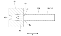
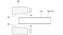
図4および図5は、第1鋼管10Aの縮径加工の方法の一例であり、第1鋼管10Aを管軸方向Xに移動させて所定形状の第1金型4Aに押し込む方法を示している。
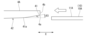
図5に示すように、第1金型4Aは、開口部4aに開口端面4bに向けて拡径する開口傾斜面41と、開口傾斜面41の基端部41aから金型4の挿入方向(管軸方向X)の奥側に向けて縮径するために形成されたピン縮径テーパー面42と、を有する。ピン縮径テーパー面42は、ピン2のピンねじ列テーパー部21の角度(ねじ列テーパー角度θ1)と同じ角度である。開口傾斜面41の傾斜角度θ3は、ピン連設部22のピンテーパー角度θ2と略同等の角度に設定されている。管軸方向Xで第1金型4A内に第1鋼管10Aを押し込むように移動させることで、縮径加工を行うことができる。
4 and 5 show an example of a method for reducing the diameter of the
As shown in FIG. 5, the
図6は、第1鋼管10Aの縮径加工の方法の他の例であり、上下から所定形状の第2金型4Bで挟み込みプレス加工で縮径する方法を示している。第2金型4Bの場合にも、上述した図5に示す第1金型4Aと同様の開口傾斜面41とピン縮径テーパー面42と、を有する。
Figure 6 shows another example of a method for reducing the diameter of the
次に、上述した鋼管ねじ継手および鋼管ねじ継手の製造方法の作用について、図1~図6に基づいて詳細に説明する。 Next, the operation of the above-mentioned steel pipe threaded joint and manufacturing method of the steel pipe threaded joint will be described in detail with reference to Figures 1 to 6.
本実施形態に係る鋼管ねじ継手1によれば、地盤に打ち込む鋼管10A、10B同士をねじ込むことによって締結する。鋼管ねじ継手1は、第1鋼管10Aの外面に雄ねじ2Aが形成されたピン2と、第2鋼管10Bの内面にピン2の雄ねじ2Aに螺合可能な雌ねじ3Aが形成されたボックス3と、を有する。
ピン2とボックス3のねじ列は、鋼管10の管軸Oに対してねじ列テーパー角度θ1で傾斜したねじ列テーパー部21、31が形成され、ピン2の最小内径D1は、第1鋼管10Aのうちピン2とボックス3とを除く本体部11A、11Bの鋼管内径D2より小さい。ピン2は、雄ねじ2Aの雄ねじ終端21aからピン本体部11Aにかけてピンテーパー角度θ2だけ傾斜したピン連設部22を有する。ピンテーパー角度θ2は、ねじ列テーパー角度θ1の2倍以下(θ2/θ1≦2)である。
According to the steel pipe threaded joint 1 of this embodiment, the
The thread rows of the
本実施形態に係る鋼管ねじ継手1によれば、第1鋼管10Aの管端を縮径し、直接加工した雄ねじ2Aを刻設したピン2と、管端に雌ねじ3Aを刻設したボックス3を螺合するねじ構造において、第1鋼管10Aと第2鋼管10Bの外径を一致させた状態で、ピン2の最小内径D1をピン本体部11Aの鋼管内径D2より小さくするとともに、ピン連設部22のピンテーパー角度θ2がねじ列テーパー角度θ1の2倍以下とすることで、鋼管10内の内空断面積を施工に支障なく確保することができ、引張強度の低下を抑えつつ、同外径のまま薄肉化することができる。そのため、本実施形態の鋼管ねじ継手1では、従来の鋼管継手部に比べて鋼管10の引張強度が高めることができ、従来の鋼管と同等の引張強度でも薄肉化が可能となり鋼管10の軽量化を図ることができる。
According to the steel pipe threaded joint 1 of this embodiment, the pipe end of the
このように鋼管10が薄肉で軽量化されることから、鋼管10を手で持って締め込む作業を軽減することができ、作業の効率化を図ることができる。そして、この場合には、鋼管10の引張強度を確保できることから、地盤への鋼管10の打設間隔等を変更させることなく打設することができる。
Because the
具体的には、図2のようにピン2に縮径加工を施したピン連設部22およびピンねじ列テーパー部21を構成ことで、無理なく雄ねじ2Aを加工することが可能となる。
すなわち、本実施形態による鋼管ねじ継手1では、ピン2の最小内径D1をピン本体部11Aの鋼管内径D2より小さくし、ピンテーパー角度θ2をねじ列テーパー角度θ1の2倍以下(θ2/θ1≦2)とすることで、ピン本体部の鋼管内径とピンの内径が一致しているねじ継手部の場合(ピンを含めて鋼管全長にわたって内径が変化しない場合)のように、雄ねじと雌ねじ自体は加工できるものの、多少の干渉を許容しても嵌め合い可能なねじ山が少なくなり、引張力が作用した際に容易にねじの抜け出し(ジャンプアウト)が発生するという従来の課題を解決することができる。
Specifically, by forming the pin connected
That is, in the steel pipe threaded joint 1 according to the present embodiment, the minimum inner diameter D1 of the
つまり、上述したピン本体部とピンの内径が一致している従来のねじ継手部の場合のように、ねじ継手に引張力が作用した際、ジャンプアウトがなければ多くの継手の場合、ボックスもしくはピンの雄ねじ終点、いわゆる危険断面から破断する。そのため、縮径加工後の鋼管にねじ継手を加工する際も、危険断面の厚さが設計通りになるよう加工を行う必要がある。加工では、鋼管の管端側から開始し、完全ねじ部を加工した後、切削工具を鋼管外径側に逃がすための継手逃がし部が必要となる。そして、ピン連設部22を設けた本実施形態では、危険断面Sをピンねじ列テーパー部21とピン連設部22の境界付近に設ける場合に、ピン連設部22に逃がし代が配置されることになる。
このとき、ピン連設部22からピン本体部11Aに至るピンテーパー角度θ2が急な角度だと、逃がし代の肉厚が危険断面Sより薄くなり、結果として引張荷重の作用時にその箇所から破断し、十分な引張強度が得られない可能性がある。そのため、ピンテーパー角度θ2をねじ列テーパー角度θ1の2倍以下(θ2/θ1≦2)とすることで、継手逃がし部23の最小肉厚tを危険断面Sに対して90%以上に断面積を確保することできる。
That is, as in the case of the conventional threaded joint in which the inner diameter of the pin body and the inner diameter of the pin are the same, when a tensile force acts on the threaded joint, in the case of many joints, if there is no jump-out, the joint will break from the end of the male thread of the box or pin, that is, the so-called dangerous cross section. Therefore, when machining a threaded joint on a steel pipe after diameter reduction, it is necessary to perform machining so that the thickness of the dangerous cross section is as designed. In machining, the process starts from the pipe end side of the steel pipe, and after machining the complete thread portion, a joint relief portion is required to allow the cutting tool to escape to the outer diameter side of the steel pipe. In this embodiment in which the
In this case, if the pin taper angle θ2 from the pin connected
なお、危険断面Sを管端側(ピン先端2a側)に移動させることで継手逃がし部23の位置をピン連設部22からピンねじ列テーパー部21に移動させることは可能だが、その場合、雄ねじ2Aの半径方向位置をより内径側に移す必要があり、その分、ピン2の内径側への張り出し量が増加するため、考慮が必要である。
It is possible to move the position of the
また、本実施形態では、鋼管10A、10B同士を締結した状態で、ピン2の最小内径D1をピン本体部11Aの鋼管内径D2に対して80%以上に制限することで、鋼管10内において掘削用ドリルやモルタル注入管等の通過を概ね許容できる。そのため、ピン2が上記範囲において鋼管10の内径側へ張り出していても、従来の鋼管内での作業を支障なく行うことが可能な鋼管内断面積を確保することができる。
In addition, in this embodiment, by limiting the minimum inner diameter D1 of the
また、本実施形態の鋼管ねじ継手1の製造方法は、第2鋼管10Bの一端に雌ねじ3Aを含むボックス3を加工する工程と、第1鋼管10Aの一端の直径を縮小する縮径加工を行う工程と、縮径加工を行った後に縮径した部分に雄ねじ2Aを含むピン2を加工する工程と、を有する。
これにより、上述した構成の鋼管ねじ継手1において、雄ねじ2Aおよび雌ねじ3Aの精度を確保し、ピン2のピンねじ列テーパー部21およびピン連設部22を効率よく加工することができる。
In addition, the manufacturing method for the steel pipe threaded joint 1 of this embodiment includes the steps of machining a
As a result, in the steel pipe threaded joint 1 configured as described above, the precision of the
上述した本実施形態による鋼管ねじ継手1および鋼管ねじ継手1の製造方法では、薄肉化および高強度化することで本体部11A、11Bの軽量化を図ることができ、鋼管10の引張強度を高めることができる。
The steel pipe threaded joint 1 and the manufacturing method for the steel pipe threaded joint 1 according to the present embodiment described above can reduce the weight of the
次に、上述した実施形態による鋼管ねじ継手1および鋼管ねじ継手1の製造方法の効果を裏付けるために行った実施例について以下説明する。 Next, examples conducted to verify the effects of the steel pipe threaded joint 1 and the manufacturing method of the steel pipe threaded joint 1 according to the above-described embodiment will be described below.
(実施例)
実施例では、上述した実施形態の鋼管ねじ継手(図2参照)を使用した表1に示す4種類(ケース1~4)の鋼管に対して構造解析にて引張強度を検証した。すなわち、ケース1~4それぞれの鋼管の鋼管ねじ継手は上述した実施形態で示すピン2とボックス3が締結される構成であり、これらケース1~4の鋼管ねじ継手の引張強度、変形、および相当応力状態を確認するため、弾塑性有限要素法(FEA)によるFEAモデルを作成し、最大荷重時に対して数値シミュレーション解析を行い、その効果を確認した。
(Example)
In the examples, the tensile strength was verified by structural analysis for four types of steel pipes (

表1は、実施例の解析で使用した各ケース1~4による鋼管ねじ継手の条件および解析結果の引張強度を示している。
表1に示すように、ケース1~4で使用する鋼管は、いずれも外径76.3mm、肉厚2.6mmの素管を対象としている。また、ケース1~4の鋼管において、鋼管ねじ継手のねじ山形状はすべて同一であり、ピン連設部のテーパー角度(ピンテーパー角度θ2)を変化させた。表1には、各ケース1~4におけるテーパー角度(°)と肉厚(mm)の条件を示している。テーパー角度は、ねじ(ピンの雄ねじとボックスの雌ねじ)のねじ列テーパー角度θ1、ピン連設部のピンテーパー角度θ2、ねじ列テーパー角度θ1とピンテーパー角度θ2とのテーパー比率(θ2/θ1)を示している。肉厚は、ピンの肉厚を示し、危険断面の肉厚t1、最小肉厚t2、危険断面の肉厚t1に対する最小肉厚t2の肉厚比率(t2/t1)を示している。
Table 1 shows the conditions of the steel pipe threaded joints for each of
As shown in Table 1, the steel pipes used in
図7は、一例として、ケース1の鋼管ねじ継手における曲げFEAモデルによる引張解析での鋼管ねじ継手の相当応力分布を示している。構造解析の結果、図7に示すように、すべてのケース1~4においてボックス3ではなくピン2の危険断面付近に応力が集中し、鋼管ねじ継手のピンが破断(ピン破断)したことが確認された。図7の符号Tは、ピン破断点を示している。
As an example, Figure 7 shows the equivalent stress distribution in a steel pipe threaded joint in tensile analysis using a bending FEA model for
ここで、引張強度の基準として、素管の引張強度の77.5%以上とした。これは前述のとおり素管の肉厚が標準より-12.5%であった場合、素管の引張強度は断面積に比例するため、標準寸法に対して12.5%の2乗、すなわち22.5%(12.5×12.5)だけ減少すると推定されるためである。 The standard for tensile strength is set at 77.5% or more of the tensile strength of the blank pipe. This is because, as mentioned above, if the thickness of the blank pipe is -12.5% smaller than the standard, the tensile strength of the blank pipe is proportional to the cross-sectional area, so it is estimated that it will decrease by 12.5% squared, or 22.5% (12.5 x 12.5), relative to the standard dimensions.
図8は、実施例による解析結果を示す図であって、テーパー比率と継手引張強度との関係を示すグラフである。図8は、横軸はテーパー比率(θ2/θ1)であり、縦軸は継手引張強度(%)であり、表1のデータをグラフ上にプロットし、それらプロットを直線で繋いだグラフである。
表1および図8に示すように、テーパー比率(θ2/θ1)が大きくなると、継手引張強度(%)が低下することがわかる。例えば、テーパー比率(θ2/θ1)が2を超えると、継手引張強度が20%以下に低下することがわかる。これにより、ピン連設部のピンテーパー角度θ2がねじ列テーパー角度θ1の2倍以下であれば、鋼管ねじ継手の継手引張強度が素管部(上記実施形態の本体部11に相当)の77.5%以上を確保できることがわかる。
Fig. 8 is a graph showing the analysis results according to the embodiment, showing the relationship between the taper ratio and the joint tensile strength, in which the horizontal axis represents the taper ratio (θ2/θ1) and the vertical axis represents the joint tensile strength (%), with the data in Table 1 plotted on the graph and the plots connected by straight lines.
As shown in Table 1 and Figure 8, it can be seen that as the taper ratio (θ2/θ1) increases, the joint tensile strength (%) decreases. For example, it can be seen that when the taper ratio (θ2/θ1) exceeds 2, the joint tensile strength decreases to 20% or less. From this, it can be seen that if the pin taper angle θ2 of the pin-connected portion is equal to or less than twice the thread row taper angle θ1, the joint tensile strength of a steel pipe threaded joint can be ensured to be 77.5% or more of that of the bare pipe portion (corresponding to the main body portion 11 in the above embodiment).
なお、一般構造用鋼管として一般的なSTK400をSTK540まで高強度化することを想定する場合、STK540の規格降伏強度は390N/mm2、規格引張強度は540N/mm2で降伏比(降伏強度/引張強度)は約72%である。仮にSTK540素管の肉厚が標準肉厚で、継手部の引張強度が素管の引張強度の77.5%であった場合、その強度は素管の降伏強度に近しい値となり素管が降伏する前に継手が破断する可能性がある。したがって、より好ましくは継手部の引張強度をSTK540の降伏比に対して10%以上高く、すなわち85%程度確保するべきであり、その際に必要なピン連設部のピンテーパー角度θ2は、図8に示すようにねじ列テーパー角度θ1に対して1.6倍以下である。 In addition, assuming that STK400, which is a general structural steel pipe, is strengthened to STK540, the standard yield strength of STK540 is 390 N/ mm2 , the standard tensile strength is 540 N/ mm2, and the yield ratio (yield strength/tensile strength) is about 72%. If the wall thickness of the STK540 mother pipe is the standard thickness and the tensile strength of the joint is 77.5% of the tensile strength of the mother pipe, the strength will be close to the yield strength of the mother pipe, and the joint may break before the mother pipe yields. Therefore, it is more preferable that the tensile strength of the joint is 10% or more higher than the yield ratio of STK540, that is, about 85%, and the pin taper angle θ2 of the pin-connected portion required in this case is 1.6 times or less the thread row taper angle θ1 as shown in FIG. 8.
以上、本発明による鋼管ねじ継手および鋼管ねじ継手の製造方法の実施形態について説明したが、本発明は前記の実施形態に限定されるものではなく、その趣旨を逸脱しない範囲で適宜変更可能である。 The above describes the embodiments of the steel pipe threaded joint and the manufacturing method of the steel pipe threaded joint according to the present invention, but the present invention is not limited to the above-mentioned embodiments and can be modified as appropriate without departing from the spirit of the invention.
例えば、本実施形態では、ピン2の最小内径D1として、鋼管10A、10B同士を締結した状態で、ピン本体部11Aの鋼管内径D2に対して80%以上が好ましいとしているが、鋼管の使用用途として、鋼管内部に掘削用ドリルやモルタル注入管等を通過させる施工がない場合においては、ピン2の本体部11の内周面11bからの張り出し量として内径比率で上記80%よりも小さく設定することも可能である。
For example, in this embodiment, the minimum inner diameter D1 of the
また、本実施形態では、トンネルの地盤補強用の土木用鋼管に適用した一例を示しており、主に地盤に対して水平あるいは斜め前方に打設される鋼管を対象としているが、地盤に対して鉛直方向に打設される鋼管杭の鋼管ねじ継手であってもかまわない。また、トンネルの施工に限定されることもない。 In addition, this embodiment shows an example of application to civil engineering steel pipes for reinforcing the ground of a tunnel, and is mainly intended for steel pipes that are driven horizontally or diagonally forward into the ground, but it may also be a steel pipe threaded joint for a steel pipe pile that is driven vertically into the ground. Furthermore, it is not limited to tunnel construction.
その他、本発明の趣旨を逸脱しない範囲で、前記した実施形態における構成要素を周知の構成要素に置き換えることは適宜可能である。 In addition, the components in the above-described embodiments may be replaced with well-known components as appropriate without departing from the spirit of the present invention.
1 鋼管ねじ継手
10、10A、10B 鋼管
2 ピン
2A 雄ねじ
3 ボックス
3A 雌ねじ
11A ピン本体部
11B ボックス本体部
11a、11c 外周面
11b、11d 内周面
21 ピンねじ列テーパー部
21a 雄ねじ終端
22 ピン連設部
31 ボックスねじ列逆テーパー部
32 ショルダー部
O 管軸
X 管軸方向
θ1 ねじ列テーパー角度(第1テーパー角度)
θ2 ピンテーパー角度(第2テーパー角度)
1 Steel pipe threaded joint 10, 10A,
θ2 Pin taper angle (second taper angle)
Claims (3)
一方の前記鋼管の外面に雄ねじが形成されたピンと、
他方の前記鋼管の内面に前記ピンの前記雄ねじに螺合可能な雌ねじが形成されたボックスと、を有し、
前記ピンと前記ボックスのねじ列は、前記鋼管の管軸に対して第1テーパー角度で傾斜したねじ列テーパー部が形成され、
前記ピンの最小内径は、前記鋼管のうち前記ピンと前記ボックスとを除く本体部の鋼管内径より小さく、
前記ピンは、前記雄ねじの完全ねじ部終端から前記本体部にかけて第2テーパー角度だけ傾斜したピン連設部を有し、
前記第2テーパー角度は、前記第1テーパー角度の2倍以下である鋼管ねじ継手。 A steel pipe threaded joint for fastening steel pipes to be driven into the ground in construction work by screwing them together,
A pin having a male thread formed on the outer surface of one of the steel pipes;
A box having an internal thread formed on the inner surface of the other steel pipe that can be screwed onto the external thread of the pin,
The thread row of the pin and the box has a thread row taper portion inclined at a first taper angle with respect to the pipe axis of the steel pipe,
The minimum inner diameter of the pin is smaller than the inner diameter of the steel pipe of the main body portion excluding the pin and the box,
The pin has a pin connecting portion inclined by a second taper angle from a terminal end of a fully threaded portion of the male screw to the main body portion,
A steel pipe threaded joint, wherein the second taper angle is not more than twice the first taper angle.
前記鋼管の一端に前記雌ねじを含む前記ボックスを加工する工程と、
前記鋼管の一端の直径を縮小する縮径加工を行う工程と、
前記縮径加工を行った後に縮径した部分に前記雄ねじを含む前記ピンを加工する工程と、
を有する鋼管ねじ継手の製造方法。 A method for producing a steel pipe threaded joint according to claim 1 or 2,
machining the box including the female thread on one end of the steel pipe;
A step of performing a diameter reduction process to reduce the diameter of one end of the steel pipe;
machining the pin including the male thread in a reduced diameter portion after the diameter reduction process;
A method for manufacturing a steel pipe threaded joint having the above structure.
Priority Applications (1)
| Application Number | Priority Date | Filing Date | Title |
|---|---|---|---|
| JP2023047079A JP2024136102A (en) | 2023-03-23 | 2023-03-23 | Steel pipe threaded joint and manufacturing method thereof |
Applications Claiming Priority (1)
| Application Number | Priority Date | Filing Date | Title |
|---|---|---|---|
| JP2023047079A JP2024136102A (en) | 2023-03-23 | 2023-03-23 | Steel pipe threaded joint and manufacturing method thereof |
Publications (1)
| Publication Number | Publication Date |
|---|---|
| JP2024136102A true JP2024136102A (en) | 2024-10-04 |
Family
ID=92911598
Family Applications (1)
| Application Number | Title | Priority Date | Filing Date |
|---|---|---|---|
| JP2023047079A Pending JP2024136102A (en) | 2023-03-23 | 2023-03-23 | Steel pipe threaded joint and manufacturing method thereof |
Country Status (1)
| Country | Link |
|---|---|
| JP (1) | JP2024136102A (en) |
-
2023
- 2023-03-23 JP JP2023047079A patent/JP2024136102A/en active Pending
Similar Documents
| Publication | Publication Date | Title |
|---|---|---|
| JP5752988B2 (en) | Concrete tap screw | |
| US6041487A (en) | Method for producing sealing surfaces on a tubular member | |
| CN114270012B (en) | Threaded joints | |
| US20180209138A1 (en) | Combined anchor and rebar assembly and method for producing the same | |
| US6293360B1 (en) | Thread joint percussive drilling equipment | |
| JP6112918B2 (en) | Pipe connection structure for civil works | |
| JP2024136102A (en) | Steel pipe threaded joint and manufacturing method thereof | |
| JP4645268B2 (en) | Joint structure of steel pipe pile for landslide prevention and steel pipe pile for landslide prevention provided with the same | |
| JP2022191473A (en) | Threaded joints for steel pipes | |
| JPH1143936A (en) | Pile joint structure | |
| JP7111136B2 (en) | steel pipe threaded joints | |
| JP2024027275A (en) | Steel pipe connection device | |
| CN111075116B (en) | Steel bar connecting device and connecting method thereof | |
| JP6533752B2 (en) | Joint structure and construction method of joint structure | |
| JP4609627B2 (en) | Joining method of ready-made piles, Joined hardware of ready-made piles | |
| JP7240950B2 (en) | Stop ring mounting jig and stop ring mounting method using the mounting jig | |
| JP7432926B2 (en) | Steel pipe connection structure | |
| JP7386565B2 (en) | Anchor bolt pilot hole drilling jig | |
| JP3248459B2 (en) | Pile with threaded joint | |
| JP2001021072A (en) | Pipe joint excellent in seizure resistance and processing method thereof | |
| JP6344225B2 (en) | Steel pipe pile joint structure | |
| JPH1068294A (en) | Wedge segment joint for shield tunnel | |
| JP2002013136A (en) | Screw joint for steel pipe pile, steel pipe pile, and construction method of burying the steel pipe pile | |
| JP2014234654A (en) | Joining structure of steel pipe constituting rotary pile | |
| JP2023167089A (en) | ring fittings |
Legal Events
| Date | Code | Title | Description |
|---|---|---|---|
| A621 | Written request for application examination |
Free format text: JAPANESE INTERMEDIATE CODE: A621 Effective date: 20250916 |
|
| A977 | Report on retrieval |
Free format text: JAPANESE INTERMEDIATE CODE: A971007 Effective date: 20260423 |