JP2024102403A - Welding control device and welding control method - Google Patents
Welding control device and welding control method Download PDFInfo
- Publication number
- JP2024102403A JP2024102403A JP2023006234A JP2023006234A JP2024102403A JP 2024102403 A JP2024102403 A JP 2024102403A JP 2023006234 A JP2023006234 A JP 2023006234A JP 2023006234 A JP2023006234 A JP 2023006234A JP 2024102403 A JP2024102403 A JP 2024102403A
- Authority
- JP
- Japan
- Prior art keywords
- welding
- image
- electrode
- wire
- arc
- Prior art date
- Legal status (The legal status is an assumption and is not a legal conclusion. Google has not performed a legal analysis and makes no representation as to the accuracy of the status listed.)
- Pending
Links
Images

Landscapes
- Arc Welding In General (AREA)
Abstract
【課題】溶接対象物のアーク溶接に用いられる電極または溶接ワイヤの位置を高い精度で制御することが可能な溶接制御装置および溶接制御方法を提供する。【解決手段】溶接中画像51に含まれる溶接ワイヤ5、電極2、および溶融池7の画像部分54と溶接前画像52とを合成した合成画像53を生成し、合成画像53から抽出した、電極2または溶接ワイヤ5と溶接対象物3との相対位置情報に基づいて、電極2または溶接ワイヤ5の位置を制御する。【選択図】 図6[Problem] To provide a welding control device and a welding control method capable of controlling with high precision the position of an electrode or welding wire used in arc welding of a welding object. [Solution] A composite image 53 is generated by combining an image portion 54 of a welding wire 5, an electrode 2, and a molten pool 7 included in an image 51 during welding with an image 52 before welding, and the position of the electrode 2 or welding wire 5 is controlled based on relative position information between the electrode 2 or welding wire 5 and the welding object 3 extracted from the composite image 53. [Selected Figure]
Description
本発明は、溶接制御装置および溶接制御方法に関わる。 The present invention relates to a welding control device and a welding control method.
アーク溶接の能率向上、高品質化のために、溶接制御の自動化や溶接状況を監視する装置について、様々な提案がされている。例えば、特許文献1および特許文献2に開示されているものが知られている。
In order to improve the efficiency and quality of arc welding, various proposals have been made for automating welding control and devices for monitoring the welding status. For example, those disclosed in
特許文献1に開示されている装置は、溶接対象物の溶接に用いられる溶接ワイヤ、又は前記溶接ワイヤを溶融させるための電極の少なくとも一方を含む位置制御対象を制御するように構成された溶接制御装置であって、少なくとも前記位置制御対象を含むように撮影した画像から検出される溶接特徴量であって、前記溶接ワイヤのワイヤ位置または前記電極の電極位置の少なくとも一方を含む溶接特徴量に基づいて前記位置制御対象の実位置を決定するように構成された第1決定部と、前記溶接対象物を溶接する際の前記電極の姿勢情報または前記溶接対象物の形状情報の少なくとも一方を含む入力条件に基づいて、前記入力条件に応じた前記実位置の目標である目標位置を決定するように構成された第2決定部と、前記実位置を前記目標位置にするための前記位置制御対象の位置制御を実行するように構成された制御部と、を備えることを特徴としている。
The device disclosed in
特許文献2に開示されている溶接状況の遠隔監視方法は、溶接部における監視対象である溶融池、アーク、開先の状態を鮮明に撮像するため600~800nmを中心波長として、100nm以下の範囲の幅の波長を透過する干渉フィルタをCCDカメラの前面に配し、シャッタースピードを選択して切り替えられる制御装置により、前記それぞれの各対象に合わせた最適なシャッタースピードによって撮像したアーク、溶融池の情報と、同様に最適なシャッタースピードによってガスシールドアーク溶接では、電圧が小さい時、ティグ溶接では、電流が小さい時に撮像した溶融池、開先内情報と画像処理装置により設定された画面のマスク位置にそれぞれを合成して、モニタ出力することで鮮明な画像を表示して、開先線倣いを含めた溶接条件制御を行うこと、を有することを特徴としている。
The method of remotely monitoring the welding status disclosed in
溶接ワイヤを溶融池に連続的に供給しながら非消耗式電極を用いて施工する自動TIG溶接では、溶接アークの変動や溶接対象物の表面状態によって電極、ワイヤの位置が適正な溶融状態からずれるため、作業者が監視、調整する必要がある。電極、ワイヤの位置制御を自動化し、作業者の負担を軽減するため、溶融池の変化や溶接対象物の表面状態を自動で検出する方法が求められている。 In automatic TIG welding, which is performed using a non-consumable electrode while continuously supplying welding wire to the molten pool, the position of the electrode and wire can deviate from the appropriate molten state due to fluctuations in the welding arc and the surface condition of the workpiece, so the operator must monitor and adjust them. To automate the position control of the electrode and wire and reduce the burden on the operator, a method is needed to automatically detect changes in the molten pool and the surface condition of the workpiece.
特許文献1に開示された装置では、位置制御対象の目標位置を溶接時の電極の姿勢や溶接対象の形状に応じて決定することにより、アーク溶接の溶接品質を向上させることが可能である。しかしながら、溶接時に撮影される画像はアーク光を抑制するフィルタにより輝度が低下するため、アーク光から離れた位置では画像が不鮮明となり、溶接対象物の表面状態の情報を取得することが難しいという課題があった。
The device disclosed in
特許文献2に開示された方法では、CCDカメラのカメラシャッタースピードを制御装置により変化させて、それぞれの対象物にあった最適な絞りで鮮明な画像を得ることが可能である。しかしながら、この方法では、TIG溶接の場合、溶接対象物の表面状態を観察できるのは、溶接電流が小さい(アーク光の輝度が低い)タイミングのみであり、それ以外のタイミングでは溶接対象物の表面状態の情報を取得できないという課題があった。
In the method disclosed in
本発明は、上記課題に鑑みてなされたものであり、その目的は、溶接対象物のアーク溶接に用いられる電極または溶接ワイヤの位置を高い精度で制御することが可能な溶接制御装置および溶接制御方法を提供することにある。 The present invention has been made in consideration of the above problems, and its purpose is to provide a welding control device and a welding control method that can control the position of the electrode or welding wire used in arc welding of the welding object with high precision.
上記目的を達成するために、本発明は、溶接対象物のアーク溶接に用いられる電極または溶接ワイヤの位置を制御する溶接制御装置において、溶接前の前記溶接対象物を含む溶接前画像、および溶接中の前記溶接対象物を含む溶接中画像を撮影する撮影装置と、前記溶接前画像に含まれる前記溶接対象物の画像部分と、前記溶接中画像に含まれる前記電極、前記溶接ワイヤ、および溶融池の画像部分とを合成した合成画像を生成する処理部と、前記合成画像から抽出した、前記電極または前記溶接ワイヤと前記溶接対象物との相対位置情報に基づいて、前記電極または前記溶接ワイヤの位置を制御する制御部とを備えるものとする。 To achieve the above object, the present invention provides a welding control device that controls the position of an electrode or welding wire used in arc welding of a welding object, the device comprising: an image capture device that captures a pre-welding image including the welding object before welding and an in-welding image including the welding object during welding; a processing unit that generates a composite image by combining an image portion of the welding object included in the pre-welding image with an image portion of the electrode, welding wire, and molten pool included in the in-welding image; and a control unit that controls the position of the electrode or welding wire based on relative position information between the electrode or welding wire and the welding object extracted from the composite image.
また、本発明は、溶接対象物のアーク溶接に用いられる電極または溶接ワイヤの位置を制御する溶接制御方法において、溶接前の前記溶接対象物を含む溶接前画像、および溶接中の前記溶接対象物を含む溶接中画像を撮影するステップと、前記溶接前画像に含まれる前記溶接対象物の画像部分と、前記溶接中画像に含まれる前記電極、前記溶接ワイヤ、および溶融池の画像部分とを合成した合成画像を生成するステップと、前記合成画像から抽出した、前記電極または前記溶接ワイヤと前記溶接対象物との相対位置情報に基づいて、前記電極または前記溶接ワイヤの位置を制御するステップとを備えるものとする。 The present invention also provides a welding control method for controlling the position of an electrode or welding wire used in arc welding of an object to be welded, comprising the steps of taking a pre-welding image including the object to be welded before welding and an in-welding image including the object to be welded during welding, generating a composite image by combining an image portion of the object to be welded included in the pre-welding image with an image portion of the electrode, the welding wire, and the molten pool included in the in-welding image, and controlling the position of the electrode or the welding wire based on relative position information of the electrode or the welding wire and the object to be welded extracted from the composite image.
本発明によれば、溶接中に撮影した溶接中画像に含まれる溶接ワイヤ、電極、および溶融池の画像部分と溶接前に撮影した溶接前画像とを合成した合成画像から抽出される、電極または溶接ワイヤと溶接対象物との正確な相対位置情報に基づいて、電極または溶接ワイヤの位置を高い精度で制御することができるため、アーク溶接の品質を向上させることが可能となる。 According to the present invention, the position of the electrode or welding wire can be controlled with high precision based on accurate relative position information between the electrode or welding wire and the workpiece to be welded, which is extracted from a composite image obtained by combining the image portions of the welding wire, electrode, and molten pool contained in the welding image taken during welding with the pre-welding image taken before welding. This makes it possible to improve the quality of arc welding.
以下、本発明の実施形態を図面を参照しつつ詳細に説明する。本発明はアーク溶接全般に適用可能であるが、本実施形態では、アーク溶接の一種であるTIG(Tungsten Inert Gas)溶接を対象とする。TIG溶接は、溶接トーチに保持されたタングステン電極と母材の間にアークを発生させ、その周囲をアルゴンなどの不活性ガスで包んで、溶加材である溶接ワイヤを補給しながら溶接を行う方法である。溶接ワイヤに通電してジュール熱を発生させ、ホットワイヤTIG溶接としてもよい。ホットワイヤTIG溶接では、高温の溶接ワイヤを溶融池内に供給することにより、ワイヤ溶着量を増加させることができる。 The following describes in detail an embodiment of the present invention with reference to the drawings. The present invention is applicable to arc welding in general, but this embodiment is directed to TIG (Tungsten Inert Gas) welding, which is a type of arc welding. TIG welding is a method in which an arc is generated between a tungsten electrode held by a welding torch and a base material, and the arc is surrounded by an inert gas such as argon, and welding is performed while supplying a filler material, a welding wire. Electricity may be passed through the welding wire to generate Joule heat, resulting in hot wire TIG welding. In hot wire TIG welding, the amount of wire deposition can be increased by supplying a high-temperature welding wire into the molten pool.
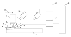
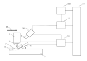
図1は、本発明の第1の実施例に係る溶接制御装置の構成図である。図1は、被溶接材3(溶接対象物)の自動TIG溶接の例を示す。図1では溶接機を省略しているが、溶接機は、溶接トーチ1にアークを発生させるための電力を供給する。溶接ワイヤ5は溶接トーチ1の前方より送給される。溶接トーチ1は移動台車に搭載する、あるいはトーチスタンドに固定したターンテーブルと組み合わせることで被溶接材3との相対位置を変更することができる。溶接ワイヤ5はワイヤ送給装置6によって自動で供給される。溶接トーチ1とワイヤ送給装置6の間には溶接中画像撮影装置10が設置される。
Figure 1 is a configuration diagram of a welding control device according to a first embodiment of the present invention. Figure 1 shows an example of automatic TIG welding of workpieces 3 (welding objects). Although the welding machine is omitted in Figure 1, the welding machine supplies power to generate an arc to the
溶接開始直前は、溶接士が溶接トーチ1を溶接開始位置に設定する。溶接開始直後は、溶接ワイヤ5を安定に溶融池7に送給するように、溶接士は駆動部13による溶接ワイヤ5の送給位置を調整する。安定に溶接施工になってからは、溶接士が制御部14を自動監視モードに切り替えて溶接を行う。溶接途中でも自動監視モードから手動溶接モードに切り替えることができる。
Just before welding begins, the welder sets the
溶接中画像撮影装置10は、例えば、デジタルカメラなどの光学カメラである。溶接中でアークが点弧している箇所から高輝度の光が発せられるため、溶接作業の動作や溶接現象などの計測対象に応じて最適な計測装置を選定する必要がある。アーク光の特性を考慮すると、可視光領域から赤外領域の波長まで含めた光を受光できるセンサを搭載したカメラとすることが望ましい。また、アーク光によって画像内の輝度が飽和するハレーションの発生を防止するため、ダイナミックレンジが大きく、露光調整が可能なカメラとすることが望ましい。
The welding
溶接中画像撮影装置10は、溶接アーク4の強い光の影響を一定程度に抑制するため、遮光フィルタ9を設ける。遮光フィルタ9を可動式とし、溶接アーク4の発生有無と連動するようにしてもよい。
The welding
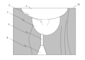
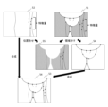
図2は、溶接中画像51の模式図である。画像中に溶接トーチ1、電極2、溶接ワイヤ5、ワイヤ送給装置6、溶融池7が映るように溶接中画像撮影装置10の位置、方向は調整される。図2において、溶接時に撮影される画像はアーク光を抑制するフィルタにより輝度が低下するため、アーク光から離れた位置では画像が不鮮明となっている。
Figure 2 is a schematic diagram of an
溶接前画像撮影装置11は、例えば、デジタルカメラなどの光学カメラであり、溶接作業を実施する前の被溶接材3の表面を撮影する。カメラは高解像度とすることが望ましい。必要に応じて、外部光源による照明を追加してもよい。
The pre-welding
図3は、溶接前画像52の模式図である。画像中に被溶接材3の壁面23、前層ビードの境界線22、被溶接材3の開先(図示せず)などが収まるように溶接中画像撮影装置10の位置、方向は調整される。
Figure 3 is a schematic diagram of a
溶接中画像51と溶接前画像52で撮影した被溶接材3の位置関係を対応付けするため、溶接中画像撮影装置10と溶接前画像撮影装置11は事前に撮影位置を校正する。これにより、溶接中画像51で撮影した被溶接材3の位置に対応する溶接前画像52がどれかを特定できるようになる。
In order to associate the positional relationship of the
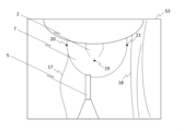
処理部12は、溶接中画像撮影装置10で撮影した溶接中画像51と、溶接前画像撮影装置11で撮影した溶接前画像52の画像処理を行う。また、図4に示すような溶接中画像51と溶接前画像52の合成画像53を生成し、合成画像53の画像処理結果に基づき、制御対象である電極2または溶接ワイヤ5の目標位置を決定し、制御部14に入力する。
The
駆動部13は、制御部14から出力された制御信号に基づき、制御対象である電極2または溶接ワイヤ5の位置を移動する。
The
制御部14は、処理部12が決定した電極2または溶接ワイヤ5の目標位置に制御するための制御信号を駆動部13に出力する。
The
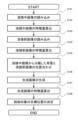
図5は、本実施例に係る溶接制御方法を示すフローチャートであり、処理部12が実行する。フローチャートの各ステップについて、図6を用いて説明する。
Figure 5 is a flowchart showing the welding control method according to this embodiment, which is executed by the
ステップS101では、溶接中画像撮影装置10で撮影した溶接中画像51を読み込む。
In step S101, the
ステップS102では、溶接中画像51の特徴点を検出する。例えば、Harrisの手法によるコーナー検出を用いて、溶接トーチ1のノズル、溶融池7、溶接ワイヤ5、ワイヤ送給装置6の境界線上にある点を検出する。また、SIFT(Scale-Invariant Feature Transform)を用いて、被溶接材3の壁面23や前層ビードの境界線22上の点を検出する。SIFTにより抽出された特徴量は、拡大・縮小によるスケール変化に対して不変なことからロバスト性が高いことが知られている。
In step S102, feature points of the
ステップS103では、溶接中画像51で撮影した被溶接材3の位置において、溶接前画像撮影装置11で撮影した溶接前画像52を読み込む。
In step S103, the
ステップS104では、溶接前画像52の特徴点を検出する。例えば、SIFTを用いて、被溶接材3の壁面23や前層ビードの境界線22上の点を検出する。
In step S104, feature points of the
ステップS105では、まず、ステップS102で算出した溶接中画像51の特徴点に基づき、溶接中画像51を溶接トーチ1のノズル、溶融池7、溶接ワイヤ5、ワイヤ送給装置6を含む画像部分である抽出領域54と、それ以外の画像部分である背景領域55に領域分けする。次に、ステップS104で検出した特徴点と、背景領域55における特徴点とを比較し、特徴点同士を対応づける。特徴点の対応付けでは、特徴量の位置がある誤差範囲内で一致していれば、対応しているとみなす。
In step S105, first, based on the feature points of the
ステップS106では、ステップS105で溶接中画像51の背景領域55に位置合わせされた溶接前画像52と溶接中画像51の抽出領域54とを合成した合成画像53を生成する。
In step S106, a
ステップS107では、合成画像53の特徴量を算出する。ここでいう特徴量は、溶接対象物3に対する電極2または溶接ワイヤ5の位置情報であり、合成画像53を基に算出してもよいし、ステップS102,S104で算出した特徴点を基に算出してもよい。
In step S107, the feature amount of the
ステップS108では、ステップS107で算出した特徴量に基づき、制御対象である電極2、溶接ワイヤ5の目標位置を決定する。例えば、図4に示すように、電極2の先端位置19、溶融池7の境界線左端20、境界線右端21、前層ビードの境界線17、被溶接材3の壁面18のそれぞれの相対位置が適切範囲となるように、電極2または溶接ワイヤ5の目標位置を決定する。
In step S108, the target positions of the
以上説明した本実施例では、溶接前画像52と溶接中画像51を合成することにより、溶接前画像52から検出した溶接対象物3の表面状態の正確な情報に基づき、制御対象である電極2または溶接ワイヤ5の溶接対象物3に対する正確な位置を取得することができる。これにより、溶接対象物3に対する電極2または溶接ワイヤ5の位置を正確に制御することができるため、アーク溶接の溶接品質を向上させることが可能となる。
In the present embodiment described above, by combining the
(まとめ)
本実施例では、溶接対象物3のアーク溶接に用いられる電極2または溶接ワイヤ5の位置を制御する溶接制御装置において、溶接前の溶接対象物3を含む溶接前画像52、および溶接中の溶接対象物3を含む溶接中画像51を撮影する撮影装置10,11と、溶接中画像51に含まれる電極2、溶接ワイヤ5、および溶融池7の画像部分54と溶接前画像52とを合成した合成画像53を生成する処理部12と、合成画像53から抽出した、電極2または溶接ワイヤ5と溶接対象物3との相対位置情報に基づいて、電極2または溶接ワイヤ5の位置を制御する制御部14とを備える。または、溶接対象物3のアーク溶接に用いられる電極2または溶接ワイヤ5の位置を制御する溶接制御方法において、溶接前の溶接対象物3を含む溶接前画像52、および溶接中の溶接対象物3を含む溶接中画像51を撮影するステップS103と、溶接中画像51に含まれる電極2、溶接ワイヤ5、および溶融池7の画像部分54と溶接前画像52とを合成した合成画像53を生成するステップS106と、合成画像53から抽出した、電極2または溶接ワイヤ5と溶接対象物3との相対位置情報に基づいて、電極2または溶接ワイヤ5の位置を制御するステップS107,S108とを備える。
(summary)
In this embodiment, a welding control device that controls the position of an
以上のように構成した本実施例によれば、溶接中に撮影した溶接中画像51に含まれる電極2、溶接ワイヤ5、および溶融池7の画像部分54と溶接前に撮影した溶接前画像52とを合成した合成画像53から抽出される、電極2または溶接ワイヤ5と溶接対象物3との正確な相対位置情報に基づいて、電極2または溶接ワイヤ5の位置を高い精度で制御することができるため、アーク溶接の品質を向上させることが可能となる。
According to this embodiment configured as described above, the position of the
また、本実施例における処理部12は、合成画像53を作成する際に、溶接中画像51から抽出した溶接対象物3の特徴点の位置と、溶接前画像52から抽出した溶接対象物3の特徴点の位置とが一致するように、溶接中画像51と溶接前画像52との位置合わせを行う。これにより、合成画像53の精度を向上させることが可能となる。
In addition, when creating the
図7は、本発明の第2の実施例に係る溶接制御装置の構成図である。第1の実施例(図1に示す)との相違点は、溶接中画像撮影装置10と溶接前画像撮影装置11を共通の撮影装置101とした点と、画像記憶部102を備えた点である。撮影装置101は、例えば、デジタルカメラなどの光学カメラであり、溶接アーク4の強い光の影響を一定程度に抑制するため、可動式の遮光フィルタ9を設ける。撮影装置101は、駆動部13によって被溶接材3との相対位置を変えることができ、撮影装置101で撮影した画像は、駆動部13による撮影装置101の制御位置情報と対応付けられて、画像記憶部102に記憶される。撮影装置101の制御位置情報は、駆動部13の駆動するモータに設置されたエンコーダ等によって取得する。画像記憶部102は、記憶するハードディスクドライブなどの情報記録媒体である。なお、図7は、駆動部13で溶接トーチ1とワイヤ送給装置6を溶接方向15に駆動する構成を例示しているが、被溶接材3を溶接方向15の反対方向に駆動する構成としても良い。
Figure 7 is a configuration diagram of a welding control device according to a second embodiment of the present invention. The difference from the first embodiment (shown in Figure 1) is that the welding
本実施例では、溶接中画像撮影装置10と溶接前画像撮影装置11を共通とするため、撮影装置がコンパクトとなる。また、溶接前画像を記憶しておくことで、溶接時から先の時刻における前層ビードの位置情報をあらかじめ評価することができるため、溶接中のある時刻だけでなく、その先の時刻における前層ビードの位置情報も活用することができる。そのため、前層ビードの変動をあらかじめ検知し、制御位置に反映するフィードフォワード制御が可能である。
In this embodiment, the welding
(まとめ)
本実施例における溶接制御装置は、撮影装置101または溶接対象物3を駆動する駆動部13を備え、処理部12は、合成画像53を作成する際に、駆動部13から取得した撮影装置101または溶接対象物3の位置情報に基づいて、溶接中画像51と溶接前画像52との位置合わせを行う。
(summary)
The welding control device in this embodiment is equipped with a
以上のように構成した本実施例においても、第1の実施例と同様に、電極2または溶接ワイヤ5の位置を高い精度で制御することができるため、アーク溶接の品質を向上させることが可能となる。
In this embodiment configured as described above, as in the first embodiment, the position of the
なお、本発明は前記した実施例に限定されるものではなく、さまざまな変形例が含まれる。例えば、前記した実施例は本発明を分かりやすく説明するために詳細に説明したものであり、必ずしも説明した全ての構成を備えるものに限定されるものではない。また、ある実施例の構成の一部を他の実施例の構成に置き換えることが可能であり、また、ある実施例の構成に他の実施例の構成を加えることも可能である。また、各実施例の構成の一部について、他の構成の追加・削除・置換をすることが可能である。 The present invention is not limited to the above-described embodiments, but includes various modified examples. For example, the above-described embodiments have been described in detail to clearly explain the present invention, and are not necessarily limited to those having all of the configurations described. It is also possible to replace part of the configuration of one embodiment with the configuration of another embodiment, and it is also possible to add the configuration of another embodiment to the configuration of one embodiment. It is also possible to add, delete, or replace part of the configuration of each embodiment with other configurations.
また、上記の各構成、機能、処理部、処理手段などは、それらの一部または全部を、例えば集積回路で設計するなどによりハードウェアで実現してもよい。また、前記の各構成、機能などは、プロセッサがそれぞれの機能を実現するプログラムを解釈し、実行することによりソフトウェアで実現してもよい。各機能を実現するプログラム、テーブル、ファイルなどの情報は、メモリや、ハードディスク、SSD(Solid State Drive)などの記録装置、または、IC(Integrated Circuit)カード、SDカード、DVD(Digital Versatile Disc)などの記録媒体に置くことができる。 Furthermore, the above-mentioned configurations, functions, processing units, processing means, etc. may be realized in hardware, in part or in whole, for example by designing them as integrated circuits. Furthermore, the above-mentioned configurations, functions, etc. may be realized in software by a processor interpreting and executing a program that realizes each function. Information such as the programs, tables, and files that realize each function can be stored in a memory, a recording device such as a hard disk or SSD (Solid State Drive), or a recording medium such as an IC (Integrated Circuit) card, SD card, or DVD (Digital Versatile Disc).
また、制御線や情報線は説明上必要と考えられるものを示しており、製品上必ずしも全ての制御線や情報線を示しているとは限らない。実際にはほとんど全ての構成が相互に接続されていると考えてもよい。 In addition, the control lines and information lines shown are those considered necessary for the explanation, and not all control lines and information lines in the product are necessarily shown. In reality, it can be assumed that almost all components are interconnected.
1…溶接トーチ、2…電極、3…被溶接材(溶接対象物)、4…溶接アーク、5…溶接ワイヤ、6…ワイヤ送給装置、7…溶融池、9…遮光フィルタ、10…溶接中画像撮影装置、11…溶接前画像撮影装置、12…処理部、13…駆動部、14…制御部、15…溶接方向、17…境界線、18…壁面、19…先端位置、20…境界線左端、21…境界線右端、51…溶接中画像、52…溶接前画像、53…合成画像、54…抽出領域(画像部分)、55…背景領域、101…撮影装置、102…画像記憶部。 1...welding torch, 2...electrode, 3...workpiece (welding object), 4...welding arc, 5...welding wire, 6...wire feeder, 7...molten pool, 9...light-shielding filter, 10...image capture device during welding, 11...image capture device before welding, 12...processing unit, 13...driving unit, 14...control unit, 15...welding direction, 17...boundary line, 18...wall surface, 19...tip position, 20...left edge of boundary line, 21...right edge of boundary line, 51...image during welding, 52...image before welding, 53...composite image, 54...extracted area (image portion), 55...background area, 101...capturing device, 102...image storage unit.
Claims (4)
溶接前の前記溶接対象物を含む溶接前画像、および溶接中の前記溶接対象物を含む溶接中画像を撮影する撮影装置と、
前記溶接中画像に含まれる前記電極、前記溶接ワイヤ、および溶融池の画像部分と前記溶接前画像とを合成した合成画像を生成する処理部と、
前記合成画像から抽出した、前記電極または前記溶接ワイヤと前記溶接対象物との相対位置情報に基づいて、前記電極または前記溶接ワイヤの位置を制御する制御部とを備える
ことを特徴とする溶接制御装置。 1. A welding control device for controlling a position of an electrode or welding wire used in arc welding of a welding object, comprising:
an imaging device that captures a pre-welding image including the welding object before welding and an in-welding image including the welding object during welding;
a processing unit that generates a composite image by combining an image portion of the electrode, the welding wire, and the molten pool included in the in-welding image with the before-welding image;
a control unit that controls a position of the electrode or the welding wire based on relative position information between the electrode or the welding wire and the work-piece, the relative position information being extracted from the composite image.
前記処理部は、前記合成画像を作成する際に、前記溶接中画像から抽出した前記溶接対象物の特徴点の位置と、前記溶接前画像から抽出した前記溶接対象物の特徴点の位置とが一致するように、前記溶接中画像と前記溶接前画像との位置合わせを行う
ことを特徴とする溶接制御装置。 2. The welding control device according to claim 1,
the processing unit, when creating the composite image, aligns the image during welding with the image before welding so that the positions of feature points of the welding object extracted from the image during welding coincide with the positions of feature points of the welding object extracted from the image before welding.
前記撮影装置または前記溶接対象物を駆動する駆動部を備え、
前記処理部は、前記合成画像を作成する際に、前記駆動部から取得した前記撮影装置または前記溶接対象物の位置情報に基づいて、前記溶接中画像と前記溶接前画像との位置合わせを行う
ことを特徴とする溶接制御装置。 2. The welding control device according to claim 1,
a drive unit that drives the imaging device or the welding object,
The welding control device is characterized in that, when creating the composite image, the processing unit aligns the in-welding image and the pre-welding image based on position information of the photographing device or the welding object obtained from the drive unit.
溶接前の前記溶接対象物を含む溶接前画像、および溶接中の前記溶接対象物を含む溶接中画像を撮影するステップと、
前記溶接中画像に含まれる前記電極、前記溶接ワイヤ、および溶融池の画像部分と前記溶接前画像とを合成した合成画像を生成するステップと、
前記合成画像から抽出した、前記電極または前記溶接ワイヤと前記溶接対象物との相対位置情報に基づいて、前記電極または前記溶接ワイヤの位置を制御するステップとを備える
ことを特徴とする溶接制御方法。 1. A welding control method for controlling a position of an electrode or welding wire used in arc welding of a welding object, comprising:
taking a pre-welding image including the workpiece before welding and an in-welding image including the workpiece during welding;
generating a composite image by combining image portions of the electrode, the welding wire, and the molten pool included in the in-welding image with the before-welding image;
and controlling a position of the electrode or the welding wire based on relative position information between the electrode or the welding wire and the work-piece, the relative position information being extracted from the composite image.
Priority Applications (1)
| Application Number | Priority Date | Filing Date | Title |
|---|---|---|---|
| JP2023006234A JP2024102403A (en) | 2023-01-19 | 2023-01-19 | Welding control device and welding control method |
Applications Claiming Priority (1)
| Application Number | Priority Date | Filing Date | Title |
|---|---|---|---|
| JP2023006234A JP2024102403A (en) | 2023-01-19 | 2023-01-19 | Welding control device and welding control method |
Publications (1)
| Publication Number | Publication Date |
|---|---|
| JP2024102403A true JP2024102403A (en) | 2024-07-31 |
Family
ID=91968753
Family Applications (1)
| Application Number | Title | Priority Date | Filing Date |
|---|---|---|---|
| JP2023006234A Pending JP2024102403A (en) | 2023-01-19 | 2023-01-19 | Welding control device and welding control method |
Country Status (1)
| Country | Link |
|---|---|
| JP (1) | JP2024102403A (en) |
Citations (3)
| Publication number | Priority date | Publication date | Assignee | Title |
|---|---|---|---|---|
| JPH08150475A (en) * | 1994-11-25 | 1996-06-11 | Mitsubishi Heavy Ind Ltd | Method for remote control of welding condition |
| JPH106006A (en) * | 1996-06-25 | 1998-01-13 | Kawasaki Steel Corp | Arc welding monitoring method and apparatus |
| JPH11104833A (en) * | 1997-10-03 | 1999-04-20 | Mitsubishi Heavy Ind Ltd | Welding line copying method during welding |
-
2023
- 2023-01-19 JP JP2023006234A patent/JP2024102403A/en active Pending
Patent Citations (3)
| Publication number | Priority date | Publication date | Assignee | Title |
|---|---|---|---|---|
| JPH08150475A (en) * | 1994-11-25 | 1996-06-11 | Mitsubishi Heavy Ind Ltd | Method for remote control of welding condition |
| JPH106006A (en) * | 1996-06-25 | 1998-01-13 | Kawasaki Steel Corp | Arc welding monitoring method and apparatus |
| JPH11104833A (en) * | 1997-10-03 | 1999-04-20 | Mitsubishi Heavy Ind Ltd | Welding line copying method during welding |
Similar Documents
| Publication | Publication Date | Title |
|---|---|---|
| US10092977B2 (en) | Welding head and method for joining a workpiece | |
| JP5279479B2 (en) | Welding area monitoring apparatus and monitoring method | |
| JP7006915B2 (en) | Welding appearance defect detection device, laser welding device, and welding appearance defect detection method | |
| JP5343772B2 (en) | Laser / visual combined sensor for welding and welding control method | |
| JPS6345911B2 (en) | ||
| EP3247523B1 (en) | Weld output control by a welding vision system | |
| JP2009195977A (en) | Automatic welding control method and automatic welding apparatus | |
| JP5947571B2 (en) | Welding robot and gap adjustment method for welding robot | |
| JP3236076B2 (en) | Welding head for measuring welding parameters and automatic welding equipment using this welding head | |
| JP2024102403A (en) | Welding control device and welding control method | |
| US11235412B2 (en) | Welding tool | |
| CN101885102A (en) | Control device and method for rear camera and welding torch follow-up applied to aluminum alloy TIG welding reverse molten pool detection | |
| JPH1058169A (en) | Teaching method in laser beam machine and device therefor | |
| JP4833588B2 (en) | Image measurement system and non-stop image measurement program creation method and execution method | |
| JP4320601B2 (en) | Work positioning device and processing machine equipped with the device | |
| JP2004216440A (en) | Laser processing machine | |
| JP2895289B2 (en) | Automatic welding copying machine | |
| JP5223537B2 (en) | Laser welding quality inspection method and apparatus | |
| JP2002239767A (en) | Laser processing monitoring equipment and lighting equipment | |
| JP3464902B2 (en) | Groove copying machine | |
| KR200248899Y1 (en) | automatic welding apparatus | |
| JP2822315B2 (en) | Laser processing equipment | |
| JPH07185810A (en) | Welding condition monitoring device and automatic welding system | |
| JP6546413B2 (en) | Image processing apparatus, welding robot system and image processing method | |
| JPH08174217A (en) | Automatic welding method and apparatus |
Legal Events
| Date | Code | Title | Description |
|---|---|---|---|
| A621 | Written request for application examination |
Free format text: JAPANESE INTERMEDIATE CODE: A621 Effective date: 20250530 |
|
| A977 | Report on retrieval |
Free format text: JAPANESE INTERMEDIATE CODE: A971007 Effective date: 20260128 |
|
| A131 | Notification of reasons for refusal |
Free format text: JAPANESE INTERMEDIATE CODE: A131 Effective date: 20260203 |