JP2024056455A - Information processing system, information processing method, and program - Google Patents
Information processing system, information processing method, and program Download PDFInfo
- Publication number
- JP2024056455A JP2024056455A JP2022163334A JP2022163334A JP2024056455A JP 2024056455 A JP2024056455 A JP 2024056455A JP 2022163334 A JP2022163334 A JP 2022163334A JP 2022163334 A JP2022163334 A JP 2022163334A JP 2024056455 A JP2024056455 A JP 2024056455A
- Authority
- JP
- Japan
- Prior art keywords
- hand
- information
- processing system
- virtual
- information processing
- Prior art date
- Legal status (The legal status is an assumption and is not a legal conclusion. Google has not performed a legal analysis and makes no representation as to the accuracy of the status listed.)
- Pending
Links
- 230000010365 information processing Effects 0.000 title claims abstract description 49
- 238000003672 processing method Methods 0.000 title claims description 5
- 230000033001 locomotion Effects 0.000 claims abstract description 86
- 238000012545 processing Methods 0.000 claims description 31
- 230000001133 acceleration Effects 0.000 claims description 19
- 230000004044 response Effects 0.000 claims description 7
- 238000005516 engineering process Methods 0.000 abstract description 6
- 210000003811 finger Anatomy 0.000 description 53
- 238000000034 method Methods 0.000 description 36
- 238000003384 imaging method Methods 0.000 description 25
- 238000001514 detection method Methods 0.000 description 23
- 239000002131 composite material Substances 0.000 description 19
- 210000003813 thumb Anatomy 0.000 description 9
- 238000010586 diagram Methods 0.000 description 8
- 238000004891 communication Methods 0.000 description 6
- 230000006870 function Effects 0.000 description 5
- 238000004364 calculation method Methods 0.000 description 4
- 238000004519 manufacturing process Methods 0.000 description 2
- 239000000203 mixture Substances 0.000 description 2
- 230000003287 optical effect Effects 0.000 description 2
- 230000004075 alteration Effects 0.000 description 1
- 210000003128 head Anatomy 0.000 description 1
- 239000004973 liquid crystal related substance Substances 0.000 description 1
- 230000004807 localization Effects 0.000 description 1
- 238000013507 mapping Methods 0.000 description 1
- 238000005259 measurement Methods 0.000 description 1
- 230000003278 mimic effect Effects 0.000 description 1
- 210000000707 wrist Anatomy 0.000 description 1
Images


Abstract

【課題】手の動きを検出して、仮想インターフェースを適切に操作可能にする技術を提供する。
【解決手段】情報処理システムは、ユーザの手に保持され、または、装着されたコントローラの慣性情報に基づき前記手の動きを判定する判定手段と、仮想インターフェースを現実空間に配置した仮想空間を表すように表示手段を制御する制御手段と、前記仮想空間において前記仮想インターフェースの位置と前記手の位置とが特定の関係にある場合には、前記判定手段により判定された前記手の動きに基づき前記仮想インターフェースを操作する操作手段と、を有する。
【選択図】図1
A technology is provided that detects hand movements and enables appropriate operation of a virtual interface.
[Solution] The information processing system has a determination means for determining hand movement based on inertia information of a controller held in or worn by a user's hand, a control means for controlling a display means to represent a virtual space in which a virtual interface is placed in real space, and an operation means for operating the virtual interface based on the hand movement determined by the determination means when there is a specific relationship between the position of the virtual interface and the position of the hand in the virtual space.
[Selected Figure] Figure 1
Description
本発明は、情報処理システム、情報処理方法、プログラムに関する。 The present invention relates to an information processing system, an information processing method, and a program.
従来より、複合現実感(Mixed Reality:MR)技術や、仮想空間(Virtual Reality:VR)技術において、ユーザがCGモデルを操作する技術が検討されている。また、このような技術では、頭部装着型の表示装置であるHMD(Head Mounted Display)が利用されることが多い。 Conventionally, techniques that allow users to operate CG models have been considered in the field of mixed reality (MR) technology and virtual reality (VR) technology. Furthermore, such technologies often use a head-mounted display (HMD).
特許文献1では、撮像装置によって手を撮像した撮像画像を用いたモーションキャプチャやSLAM(Stimultaneous Localization and Mapping)などによって、CGモデルを移動させる方法などが記載されている。特許文献2では、HMDに搭載した装置によって手を撮像した撮像画像などを用いて、ユーザの手の動きをトラッキングして、CGモデルのスイッチを操作する方法について記載されている。 Patent Document 1 describes a method of moving a CG model using motion capture or SLAM (Stimulant Localization and Mapping) that uses an image of the hand captured by an imaging device. Patent Document 2 describes a method of tracking the movement of the user's hand using an image of the hand captured by a device mounted on an HMD to operate a switch on a CG model.
しかしながら、上述の技術では、撮像画像に手が写っていない場合には、適切に手の動きを検出して、仮想インターフェースを操作することができないという課題があった。 However, the above technology had the problem that if the hand was not captured in the captured image, it was not possible to properly detect hand movements and operate the virtual interface.
そこで、本発明は、手の動きを検出して、仮想インターフェースを適切に操作可能にする技術を提供することを目的とする。 The present invention aims to provide a technology that detects hand movements and enables appropriate operation of a virtual interface.
本発明の1つの態様は、
ユーザの手に保持され、または、装着されたコントローラの慣性情報に基づき前記手の動きを判定する判定手段と、
仮想インターフェースを現実空間に配置した仮想空間を表すように表示手段を制御する制御手段と、
前記仮想空間において前記仮想インターフェースの位置と前記手の位置とが特定の関係にある場合には、前記判定手段により判定された前記手の動きに基づき前記仮想インターフェースを操作する操作手段と、
を有することを特徴とする情報処理システムである。
One aspect of the present invention is a method for producing a composition comprising the steps of:
A determination means for determining a movement of a hand based on inertial information of a controller held by or attached to a user's hand;
a control means for controlling a display means so as to display a virtual space in which the virtual interface is arranged in a real space;
an operating means for operating the virtual interface based on the movement of the hand determined by the determining means when a position of the virtual interface and a position of the hand have a specific relationship in the virtual space;
The information processing system is characterized by having the following features.
本発明の1つの態様は、
ユーザの手に保持され、または、装着されたコントローラの慣性情報に基づき前記手の動きを判定する判定ステップと、
仮想インターフェースを現実空間に配置した仮想空間を表すように表示手段を制御する制御ステップと、
前記仮想空間において前記仮想インターフェースの位置と前記手の位置とが特定の関係にある場合には、前記判定ステップにおいて判定された前記手の動きに基づき前記仮想イ
ンターフェースを操作する操作ステップと、
を有することを特徴とする情報処理方法である。
One aspect of the present invention is a method for producing a composition comprising the steps of:
a determining step of determining a movement of the hand based on inertial information of a controller held in or attached to a user's hand;
a control step of controlling a display means to display a virtual space in which the virtual interface is arranged in a real space;
an operation step of operating the virtual interface based on the movement of the hand determined in the determination step when a position of the virtual interface and a position of the hand have a specific relationship in the virtual space;
The information processing method is characterized by having the following features.
本発明によれば、手の動きを検出して、仮想インターフェースを適切に操作できる。 The present invention allows hand movements to be detected and allows appropriate operation of a virtual interface.
以下に、本発明の好ましい実施の形態を、添付の図面に基づいて詳細に説明する。 A preferred embodiment of the present invention will be described in detail below with reference to the accompanying drawings.
<実施形態1>
図1を参照して、実施形態1に係る情報処理システム1について説明する。情報処理システム1は、HMD100、画像処理装置110、およびコントローラ120を有する。
<Embodiment 1>
An information processing system 1 according to the first embodiment will be described with reference to Fig. 1. The information processing system 1 includes an HMD 100, an
HMD100は、ユーザの頭部に装着される頭部装着型の表示装置(電子機器)である。HMD100には、HMD100がユーザの正面の範囲を撮像した撮像画像と、HMD100の姿勢に応じた形態のCG(コンピュータグラフィックス)などのコンテンツとが合成された合成画像が表示される。 The HMD 100 is a head-mounted display device (electronic device) that is worn on the user's head. The HMD 100 displays a composite image that combines an image captured by the HMD 100 of the area in front of the user with content such as CG (computer graphics) in a form that corresponds to the posture of the HMD 100.
画像処理装置110は、HMD100を制御する制御装置(情報処理装置;電子機器)である。画像処理装置110は、例えば、スマートフォン、タブレット端末、またはPC(パーソナルコンピュータ)である。画像処理装置110は、無線または有線によりHMD100と接続される。画像処理装置110は、撮像画像とCG(仮想操作インターフェースなど)とを合成することにより合成画像を生成して、合成画像をHMD100に送信する。なお、画像処理装置110の各構成は、HMD100が有していてもよい。
The
コントローラ120は、HMD100の各種制御を行うための装置である。コントローラ120は、CGにより表現された仮想操作インターフェース(仮想ダイヤルまたは仮想スライダーなど)に対するユーザ操作を受け付ける。コントローラ120の形状は、例えば、図1に示すように、ユーザの指に装着可能なような指輪型(リング型)の形状である。コントローラ120がユーザの指に装着可能であれば、ユーザはコントローラ120を保持しながらも自由に手を動かすことができる。コントローラ120は、Bluetoothによる無線通信を画像処理装置110と行う。
The
(HMDの内部構成)
図2を参照して、HMD100の内部構成を説明する。HMD100は、HMD制御部
201、撮像部202、画像表示部203、姿勢センサ部204を有する。
(Internal configuration of HMD)
The internal configuration of the
HMD制御部201は、HMD100の各構成を制御する。HMD制御部201は、画像処理装置110から合成画像(撮像部202がユーザの正面の空間を撮像した撮像画像と、CGとが合成された画像)を取得すると、合成画像を画像表示部203に表示する。このため、ユーザは、HMD100を装着することにより、画像表示部203に表示される合成画像を見ることができる。ユーザは、現実空間にCGが融合したような、様々な複合現実(仮想空間)を体験することができる。
The HMD
撮像部202は、2台のカメラ(撮像装置)を含む。2台のカメラは、ユーザが通常時に見ている空間と同様の空間を撮像するために、HMD100の装着時のユーザの左右の眼の位置の近くに配置される。2台のカメラが撮像により被写体(ユーザの正面の範囲)を撮像した画像は、画像処理装置110に出力される。また、撮像部202における2台のカメラは、ステレオカメラによる測距により、2台のカメラから被写体までの距離の情報を距離情報として取得できる。
The
画像表示部203は、現実空間にCGが配置された仮想空間を表す合成画像を表示する。画像表示部203は、例えば、液晶パネルまたは有機ELパネルなどを有する。ユーザがHMD100を装着している状態では、ユーザのそれぞれの眼の前に有機ELパネルが配される。
The
姿勢センサ部204は、HMD100の姿勢(および位置)を検出する。そして、姿勢センサ部204は、HMD100の姿勢(および位置)に対応するような、ユーザ(HMD100を装着したユーザ)の姿勢を検出(取得)する。姿勢センサ部204は、慣性計測装置(IMU;Inertial Measurement Unit)を有する。姿勢センサ部204は、ユーザの姿勢の情報(姿勢情報)を、画像処理装置110に出力する。
The
(画像処理装置の内部構成)
図2を参照して、画像処理装置110の内部構成を説明する。画像処理装置110は、制御部211、コンテンツDB212、通信部213を有する。
(Internal configuration of image processing device)
The internal configuration of the
制御部211は、画像処理装置110の各構成を制御する。また、制御部211は、HMD100およびコントローラ120を制御することもできる。
The
制御部211は、撮像部202が取得した画像(撮像画像)と、姿勢センサ部204が取得した姿勢情報とをHMD100から受け取る。制御部211は、撮像部202の光学系と画像表示部203の光学系における収差をキャンセルするような画像処理を撮像画像に行う。そして、制御部211は、撮像画像と任意のCGとを合成して、合成画像を生成する。つまり、制御部211は、現実空間(撮像画像が表す空間)にCGが配置された仮想空間を表す合成画像を生成する。制御部211は、HMD100におけるHMD制御部201に合成画像を送信する。
The
なお、制御部211は、HMD100が取得した情報(距離情報および姿勢情報)に基づき、合成画像におけるCGの位置、向き、および大きさを制御することもできる。例えば、制御部211は、合成画像が表す空間において、現実空間に存在する特定の物体の近くに、CGが示す仮想物体を配置する場合には、特定の物体と撮像部202との距離が近いほど仮想物体(CG)を大きくする。このようにCGの位置、向きおよび大きさを制御することにより、制御部211は、現実空間に配置されていないCGの物体が、あたかも現実空間に配置されているかのような合成画像を生成することができる。
The
コンテンツDB212は、CGなどの情報を格納する記憶部である。なお、制御部211は、コンテンツDB212から読み出すCG(つまり、合成画像の生成に用いるCG)を切り替えることが可能である。
The
(コントローラの内部構成)
図2を参照して、コントローラ120の内部構成を説明する。コントローラ120は、コントローラ制御部221、検出部222、通信部223を有する。
(Internal structure of the controller)
The internal configuration of the
コントローラ制御部221は、コントローラ120の各構成を制御する。
The
検出部222は、加速度センサ(加速度情報を取得するセンサ)または/およびジャイロセンサ(角速度情報を取得するセンサ)を含む。検出部222は、コントローラ120の慣性情報(加速度情報または角速度情報など)を取得する。また、検出部222は、慣性情報に基づき、ユーザの手の動きを検出することができる。手の動きは、例えば、手の移動ベクトル(移動情報)または手の回転角により表わすことができる。なお、実施形態1では、手にコントローラ120が装着されているため、コントローラ120の動きは、手の動きであるといえる。
The
通信部223は、画像処理装置110(通信部213)との無線通信を行う。通信部223は、例えば、コントローラ120の慣性情報、または慣性情報から検出したユーザの手の動きの情報を、画像処理装置110に送信する。
The
なお、画像処理装置110(情報処理装置)は、コントローラ120の構成の一部またはHMD100の構成の一部を有していてもよい。例えば、コントローラ120は、検出部22のうち慣性情報を取得する構成のみを有し、画像処理装置110は、慣性情報から手の動きを検出(判定)する構成を有していてもよい。
The image processing device 110 (information processing device) may have part of the configuration of the
図3~図6Bを参照して、ダイヤルまたはスライダーなどの仮想操作インターフェース(仮想インターフェース)の操作の例について説明する。ここでは、音量調整用の仮想ダイヤル300および仮想スライダー301を操作する例について説明する。仮想ダイヤル300は、後述するxy平面における手(手首)の回転に応じて操作可能である。仮想ダイヤル300の操作に応じて音量が制御される。仮想スライダー301は、後述するxy平面における手の移動に応じて操作可能である。仮想スライダー301の操作に応じて音量が制御される。なお、仮想ダイヤル300および仮想スライダー301に限らず、手の動きに応じて操作されるべき仮想操作インターフェース(例えば、仮想レバーなど)であれば、以下の説明は適用可能である。
With reference to Figures 3 to 6B, an example of operating a virtual operation interface (virtual interface) such as a dial or slider will be described. Here, an example of operating a
図3は、現実空間と、画像表示部203に表示された合成画像との関係を示す。ここでは、現実空間の座標系を座標(x,y,z)で表し、HMD100内の撮像部202が取得した撮像画像(二次元画像)の座標系を座標(h,v)で表す。合成画像では、撮像部202が家とユーザの手を撮像した撮像画像(現実空間の画像)に、音量調整用の仮想ダイヤル300と音量調整用の仮想スライダー301が重畳されている。
Figure 3 shows the relationship between the real space and the composite image displayed on the
(仮想ダイヤルの操作)
図4A、図4Bおよび図5を参照して、仮想ダイヤル300の操作を説明する。以降では、時刻tにおける現実空間をコントローラ120の位置の座標を、座標(x(t),y(t),z(t))として表現する。
(Virtual dial operation)
4A, 4B, and 5, the operation of the
以下では、制御部211は、HMD100内の撮像部202が取得した撮像画像から得
られるユーザの手の位置の情報と、コントローラ120の検出部222から得られるユーザの手の動きの情報とに基づき、仮想ダイヤル300を操作する。
In the following, the
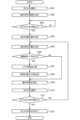
まず、図5のフローチャートを参照して、仮想ダイヤル300の操作の流れを説明する。図5のフローチャートの処理は、ユーザがメニューにおいて音量調整の項目を選択した場合に開始する。
First, the operation flow of the
ステップS501で、制御部211は、仮想ダイヤル300をHMD100の画像表示部203に表示する。つまり、制御部211は、仮想ダイヤル300を現実空間に配置した仮想空間を表す合成画像を、画像表示部203に表示する。このとき、制御部211は、図4Aに示すように、現実空間における仮想ダイヤル300の中央位置の座標(xc(0),yc(0),zc(0))を取得する。
In step S501, the
ステップS502で、制御部211は、図6Aに示すように、現実空間における仮想ダイヤル300の操作受付範囲600を設定する。例えば、制御部211は、仮想ダイヤル300の中央位置の座標(xc(0),yc(0),zc(0))を中心として、特定の長さの半径を有するような円を設定する。そして、制御部211は、その円に含まれる範囲を操作受付範囲600として設定する。
In step S502, the
なお、制御部211は、図6Bに示すように、1つの仮想ダイヤル300の周辺に複数の仮想操作インターフェースが存在する場合には、その仮想ダイヤル300と他の仮想操作インターフェースとの距離が特定の距離より近いか否かを判定する。そして、制御部211は、仮想ダイヤル300と他の仮想操作インターフェースとの距離が特定の距離より近い場合には、この仮想ダイヤル300の操作受付範囲600を狭める。これによって、複数の仮想操作インターフェース間の距離が短い場合であっても、操作受付範囲600を狭めることで、複数の操作受付範囲600同士が重複する可能性を低減できる。このため、複数の仮想操作インターフェース間における操作対象の切り替えをスムーズに行うことが可能となる。
As shown in FIG. 6B, when there are multiple virtual operation interfaces around one
ステップS503で、制御部211は、撮像画像に基づき、ユーザの指が仮想ダイヤル300に触れたか否かを判定する。このとき、まず。制御部211は、撮像画像における指(コントローラ120)の位置の座標(h,v)を現実空間における座標(x,y,z)に変換する。その後、制御部211は、座標(x,y,z)が操作受付範囲600に含まれるか否かで、指が仮想ダイヤル300に触れたか否かを判定する。これによれば、仮想ダイヤル300への接触の有無の誤検知を防ぐことができる。なお、座標(h,v)から座標(x,y,z)への変換には、例えば、撮像部202が取得した距離情報も用いるとよい。また、指が仮想ダイヤル300に触れたか否かは、指の座標と仮想ダイヤル300の中心位置の座標との距離が所定の距離より短いか否かにより判定されてもよい。
In step S503, the
そして、ステップS503で、ユーザの指が仮想ダイヤル300に触れたと判定された場合(指の位置が操作受付範囲600に含まれると判定された場合)には、ステップS504に進む。ユーザの指が仮想ダイヤル300に触れていないと判定された場合(指の位置が操作受付範囲600に含まれないと判定された場合)には、ステップS503の処理が繰り返される。 If it is determined in step S503 that the user's finger has touched the virtual dial 300 (if it is determined that the finger position is within the operation acceptance range 600), the process proceeds to step S504. If it is determined that the user's finger has not touched the virtual dial 300 (if it is determined that the finger position is not within the operation acceptance range 600), the process of step S503 is repeated.
ステップS504で、制御部211は、撮像画像に基づき、コントローラ120(コントローラ120を装着した指)の初期位置の座標(x(0),y(0),z(0))と、親指の初期位置の座標(xt(0),yt(0),zt(0))を決定する。ステップS504では、初期位置は、指が仮想ダイヤル300に触れたと判定された時刻t=0の時点での位置である。さらに、制御部211は、下記の式1よりxy平面における、仮想ダ
イヤル300の中心位置とコントローラ120の距離Lを算出する(図4A参照)。
![]()
![]()
また、制御部211は、下記の式2により、xy平面における、親指と仮想ダイヤル300の中心位置との距離Ltを算出する(図4A参照)。
![]()
![]()
そして、制御部211は、下記の式3により、仮想ダイヤル300の中央位置と親指の位置とを結んだ線分と、コントローラ120の位置と仮想ダイヤル300の中央位置とを結んだ線分とが形成する角度θtを算出する(図4A参照)。

ステップS505で、制御部211は、コントローラ120(コントローラ120が装着された指)の現在位置を決定する。制御部211は、コントローラ120の加速度情報(ax(t),ay(t),az(t))に基づき、コントローラ120の現在位置の座標(x(t),y(t),z(t))を決定する。なお、制御部211は、撮像部202が指を撮像している場合には、加速度情報に加えて、撮像画像から得られるコントローラ120の位置の座標(h(t),v(t))に基づき、座標(x(t),y(t),z(t))を決定してもよい。
In step S505, the
初めに、制御部211は、検出部222を制御して、手の動きを検出(判定)する。具体的には、検出部222は、手の動きを表す情報として、コントローラ120の初期位置の座標(x(0),y(0),z(0))からの移動情報(Δx(t),Δy(t),Δz(t))を算出(検出)する。
First, the
移動情報(Δx(t),Δy(t),Δz(t))を算出するために、検出部222は、検出した加速度を2回積分する。例えば、検出部222は、下記の式4により、x軸方向の加速度ax(t)を用いて、時刻t=0から時刻t=Tまでのx軸方向の移動情報Δx(t)を算出することができる。なお、式4に示すような計算は、x軸方向、y軸方向、およびz軸方向のそれぞれに対して行われる。
![]()
![]()
そして、制御部211は、初期位置の座標(x(0),y(0),z(0))に移動情報(Δx(t),Δy(t),Δz(t))を加算した値を、コントローラ120の現在位置の座標(x(t),y(t),z(t))として決定する。移動情報に応じて現在位置を算出することによって、撮像部202から得られる撮像画像において指(コントローラ120)が検出できない場合でも、仮想ダイヤル300を適切に操作することが可能となる。
The
ステップS506で、制御部211は、撮像部202が取得した撮像画像に手が含まれているか否かを判定する。撮像画像に手が含まれていると判定された場合には、ステップ
S507に進む。撮像画像に手が含まれていないと判定された場合には、ステップS509に進む。
In step S506, the
ステップS507で、制御部211は、図7Bで示すように、仮想ダイヤル300をつかんでいる指の位置が、仮想ダイヤル300の中心位置を中心とする回転以外で、水平方向および垂直方向にどれだけシフトしているかを判定する。言い換えると、制御部211は、検出した手の動きが、手の回転以外の動きをどれほど含むのかを判定する。具体的には、制御部211は、コントローラ120の移動情報のうちの、手の回転以外に対応するxy平面における移動情報をシフト情報(Δxs,Δys,0)として算出(判定)する。
In step S507, the
制御部211は、コントローラ120の現在位置の座標(x(t),y(t),z(t))に加え、ステップS504の時点におけるコントローラ120の位置と親指の位置と仮想ダイヤル300の位置の関係に基づき、シフト情報(Δxs,Δys,0)を算出する。具体的には、制御部211は、コントローラ120の現在位置の座標(x(t),y(t),z(t))に加えて、ステップS504で求めた距離Lと距離Ltを用いて、x軸方向およびy軸方向へのシフト情報(Δxs,Δys,0)を算出する(図7B参照)。
The
まず、制御部211は、親指の現在位置の座標(xt(t),yt(t),zt(t))からxy平面上に距離Ltだけ離れた位置であって、座標(x(t),y(t),z(t))からxy平面上に距離Lだけ離れた位置に、点Pを決定する。ここで、点Pの座標(xc(t),yc(t),zc(t))と親指の位置の座標(xt(t),yt(t),zt(t))とを結んだ線分と、点Pの座標とコントローラ120の現在位置の座標(x(t),y(t),z(t))とを結んだ線分とが、角度θtを形成するように、点Pは決定される。
First, the
そして、制御部211は、下記の式5のように、点Pの座標(xc(t),yc(t),zc(t))と仮想ダイヤル300の中央位置の座標(xc(0),yc(0),zc(0))との差分(x軸方向およびy軸方向の差分)を算出する。制御部211は、この計算結果をシフト情報(Δxs,Δys,0)として設定(判定)する。
![]()
![]()
ステップS508で、制御部211は、仮想ダイヤル300の中央位置の座標とコントローラ120の初期位置の座標を補正(再度設定)する。具体的には、制御部211は、式6に示すように、仮想ダイヤル300の中央位置の座標(xc(0),yc(0),zc(0))とコントローラ120の初期位置の座標(x(0),y(0),z(0))とに、シフト情報(Δxs,Δys,0)を加算する。以降、補正された仮想ダイヤル300の中央位置の座標を座標(xc(t),yc(t),zc(t))と表し、補正されたコントローラ120の初期位置の座標を座標(x0(t),y0(t),z0(t))と表す。補正された仮想ダイヤル300の中央位置の座標は、上述の点Pの座標と同一である。これによれば、ユーザが仮想操作インターフェースを操作する場合には、指の位置が仮想操作インターフェースのCGの位置からずれてしまうことがあるが、その場合でも適切な操作を継続することができる。

ステップS509で、制御部211は、ユーザの手の動きのうちxy平面における手の回転を判定(検出)する。具体的には、制御部211は、手の回転角度を表す動作角度θ(t)を決定する。動作角度θ(t)は、例えば、ステップS508の処理が行われた場合には、下記の式7に示すように決定することができる。式7では、コントローラ120の現在位置の座標(x(t),y(t),z(t))と仮想ダイヤル300の中央位置の座標(xc(t),yc(t),zc(t))とコントローラ120の初期位置の座標(x0(t),y0(t),z0(t))が用いられる。

なお、制御部211は、ステップS508の処理が行われていない場合には、座標(xc(t),yc(t),zc(t))の代わりに仮想ダイヤル300の中央位置の座標(xc(0),yc(0),zc(0))を用いる。また、この場合には、制御部211は、座標(x0(t),y0(t),z0(t))の代わりにコントローラ120の初期位置の座標(x(0),y(0),z(0))を用いる。
When the processing of step S508 has not been performed, the
ステップS510で、制御部211は、動作角度θ(t)だけ仮想ダイヤル300を操作する。例えば、制御部211は、仮想ダイヤル300を動作角度θ(t)だけ回転させる。これによって、仮想ダイヤル300の持ち方が異なっていても、手の回転した角度が同じであれば同一の結果が得られる。
In step S510, the
ステップS511で、制御部211は、仮想ダイヤル300から指が離れたか否かを判定する。具体的には、制御部211は、ステップS502と同様の方法によって、指の位置が操作受付範囲600に含まれるか否かを判定する。操作受付範囲600に指の位置が含まれない(仮想ダイヤル300から指が離れた)と判定された場合には、ステップS512に進む。操作受付範囲600に指の位置が含まれている(仮想ダイヤル300から指が離れていない)と判定された場合には、ステップS505に戻る。
In step S511, the
ステップS512で、制御部211は、仮想ダイヤル300の表示を終了する。これにより、音量の調整が終わる。
In step S512, the
(仮想スライダーの操作)
図9のフローチャートを参照して、仮想スライダー301の操作の例について説明する。なお、以下では、図3に示す、音量調整用の仮想スライダー301の例について説明する。なお、図9のフローチャートの処理は、メニューにおいて音量調整の項目が選択されると、開始する。
(Virtual slider operation)
An example of the operation of the
ステップS901で、制御部211は、図8Aに示すように、仮想操作インターフェースとして仮想スライダー301を、画像表示部203に表示する。つまり、制御部211は、現実空間に仮想スライダー301を配置した仮想空間を表す合成画像を画像表示部203に表示する。
In step S901, the
ステップS902で、制御部211は、仮想スライダー301の操作受付範囲600を決定する。制御部211は、仮想ダイヤル300の例の場合と同様に、仮想スライダー301に近接する他の仮想操作インターフェースが存在するか否かに応じて、操作受付範囲600の大きさを制御してもよい。つまり、制御部211は、仮想空間における複数の仮想操作インターフェース間(複数の仮想インターフェース間)の距離に応じて、複数の仮想操作インターフェースそれぞれの操作受付範囲600を制御してもよい。
In step S902, the
ステップS903で、制御部211は、ステップS503と同様に、撮像画像に基づき、ユーザの指(手)が仮想スライダー301に触れたか否かを判定する。指が仮想スライダー301に触れたか否かは、指が仮想ダイヤル300に触れたか否かの判定方法と同様の方法により判定できる。指が仮想スライダー301に触れたと判定された場合には、ステップS904に進む。指が仮想スライダー301に触れていないと判定された場合には、ステップS903の処理が繰り返される。
In step S903, the
ステップS904で、制御部211は、図8Aに示すように、撮像画像に基づき、コントローラ120(コントローラ120を装着した指)の初期位置の座標(x(0),y(0),z(0))を決定する。
In step S904, the
ステップS905で、制御部211は、コントローラ120(コントローラ120を装着した指)の現在位置を決定する。制御部211は、検出部222が取得した加速度情報(ax(t),ay(t),az(t))に基づき、コントローラ120の現在位置の座標(x(t),y(t),z(t))を決定する(図8B参照)。制御部211は、撮像部202が指を撮像している場合には、加速度情報に加えて、撮像画像から得られる指の位置の座標(h,v)に基づき、コントローラ120の現在位置の座標(x(t),y(t),z(t))を決定してもよい。
In step S905, the
初めに、制御部211は、検出部222を制御して、手の動きを判定(検出)する。具体的には、検出部222は、手の動きを表す情報として、初期位置の座標(x(0),y(0),z(0))からの移動情報(Δx(t),Δy(t),Δz(t))を算出する。移動情報(Δx(t),Δy(t),Δz(t))を算出するために、検出部222は、検出される加速度を2回積算する。検出部222は、例えば、下記の式8に示すように、x軸方向の加速度ax(t)を用いて、時刻t=0から時刻t=Tまでのx軸方向の移動情報Δxを算出する。なお、式8に示すような計算は、x軸方向、y軸方向、およびz軸方向のそれぞれについて行われる。
![]()
![]()
そして、制御部211は、初期位置の座標(x(0),y(0),z(0))に移動情報(Δx(t),Δy(t),Δz(t))を加算した値を、コントローラ120の現在位置の座標(x(t),y(t),z(t))として決定する。
Then, the
ステップS906では、制御部211は、下記の式9に示すように、xy平面における手の動きの量を表す、動作距離L(t)を決定する。式9では、コントローラ120の現
在位置の座標(x(t),y(t),z(t))と、コントローラ120の初期位置(x(0),y(0),z(0))が用いられる。
![]()
![]()
ステップS907で、制御部211は、動作距離L(t)だけ仮想スライダー301を操作する。例えば、制御部211は、図8Aおよび図8Bに示すように、バー310を動作距離L(t)だけ移動させる。
In step S907, the
ステップS908で、制御部211は、仮想スライダー301から指が離れたか否かを判定する。具体的には、制御部211は、操作受付範囲600に指の位置が含まれているか否かを判定する。操作受付範囲600に指の位置が含まれていないと判定された場合には、ステップS909に進む。操作受付範囲600に指の位置が含まれていると判定された場合には、ステップS905に戻る。
In step S908, the
ステップS909で、制御部211は、仮想スライダー301の表示を終了する。
In step S909, the
以上、撮像部202を必ず用いるのは、仮想操作インターフェースとの接触を検出する場合のみであり、以降の処理では、撮像部202を用いず検出部222のみを用いて、仮想操作インターフェースを操作することも可能である。そのため、接触の検出後に、撮像画像からユーザの手が検出できない場合であっても、検出部222から取得した慣性情報を用いて、仮想操作インターフェースの操作を続けることが可能である。なお、撮像画像からユーザの手が検出できない場合とは、ユーザの手が撮像部202の撮像範囲外に出ることで手が検出できなくなった場合または、撮像画像内で手の甲などに隠れてユーザの指が検出できなくなった場合などである。
As described above, the
また、HMDと通信しない操作部材(ダイヤルやスライダーなど)を模した模型を認識し、その模型にCGを重ね合わせたものを操作インターフェースとして用いることも可能である。この場合には、図10に示すように、物理的な操作が可能な操作部材のように、操作インターフェースを使用することが可能となる。 It is also possible to recognize models that mimic operating members (dials, sliders, etc.) that do not communicate with the HMD, and overlay CG on the models to use as an operating interface. In this case, as shown in Figure 10, it becomes possible to use the operating interface as if it were an operating member that can be physically operated.
<実施形態2>
以下、図11を参照して、実施形態2に係る仮想操作インターフェースの操作方法について説明する。以下では、実施形態1と異なる箇所についてのみ説明する。
<Embodiment 2>
The method of operating the virtual operation interface according to the second embodiment will be described below with reference to Fig. 11. Only the differences from the first embodiment will be described below.
実施形態2において、仮想ダイヤル300の操作の流れが実施形態1とは異なるため、仮想ダイヤル300の操作の流れについて図11に示すフローチャートを参照して説明する。
In the second embodiment, the operation flow of the
ステップS1101~S1103では、図5に示すステップS501~S503と同様の処理が行われる。 In steps S1101 to S1103, the same processing as in steps S501 to S503 shown in Figure 5 is performed.
ステップS1104で、制御部211は、仮想ダイヤル300の大きさが所定のサイズ以上であるか否かを判定する。仮想ダイヤル300の大きさが所定のサイズ以上であると判定された場合には、ステップS1105に進む。仮想ダイヤル300の大きさが所定のサイズ未満であると判定された場合には、ステップS504に進み、それ以降では図5に示すフローチャートの処理が行われる。
In step S1104, the
ステップS1105で、制御部211は、撮像画像から人指し指の先端が検出されたか
否かを判定する。人差し指の先端が検出されたと判定された場合には、ステップS1106に進む。人差し指の先端が検出されていないと判定された場合には、ステップS504に進み、それ以降では図5に示すフローチャートの処理が行われる。なお、人指し指の先端ではなく、コントローラ120が撮像画像から検出されたか否かが判定されてもよい。
In step S1105, the
ステップS1106で、制御部211は、コントローラ120(コントローラ120を装着した人差し指)の初期位置を決定する。具体的には、制御部211は、撮像部202から取得した撮像画像に基づき、コントローラ120の初期位置の座標(x(0),y(0),z(0))を決定する。また、制御部211は、撮像画像に基づき、親指の初期位置の座標(xt(0),yt(0),zt(0))を決定する。
In step S1106, the
さらに、制御部211は、ステップS504と同様に、上記の式1によりxy平面における仮想ダイヤル300の中心位置とコントローラ120の距離Lを算出する。制御部211は、上記の式2によりxy平面における親指と仮想ダイヤル300の中心位置との距離Ltを算出する。そして、制御部211は、上記の式3により、仮想ダイヤル300の中央位置と親指の位置とを結んだ線分と、コントローラ120の位置と仮想ダイヤル300の中央位置とを結んだ線分とが形成する角度θtを算出する。
Furthermore, similar to step S504, the
ステップS1107で、制御部211は、コントローラ120(コントローラ120を装着した人差し指)の現在位置の座標(x(t),y(t),z(t))を決定する。ここでは、制御部211は、撮像部202から取得した撮像画像におけるコントローラ120の位置の座標(h(t),v(t))を変換することにより、コントローラ120の現在位置の座標(x(t),y(t),z(t))を決定する。
In step S1107, the
ステップS1108~S1113では、図5に示すステップS507~S512と同様の処理が行われる。 In steps S1108 to S1113, the same processing as in steps S507 to S512 shown in Figure 5 is performed.
このように、制御部211は、仮想ダイヤル300が大きい場合には、撮像画像(撮像部202による撮像結果)のみからコントローラ120(コントローラ120が装着された指)の位置を決定する。このことにより、処理に必要な負荷を減らすことができる。なお、仮想ダイヤル300が大きい場合には、手の動きが大きくなるため、撮像画像のみから手の動きを正確に判定できる可能性が高い。このため、コントローラ120の慣性情報を用いずに、適切に仮想操作インターフェースを操作することができる。
In this way, when the
<実施形態3>
以下、図12A、図12Bおよび図13を参照して、実施形態3に係る仮想操作インターフェースの操作方法について説明する。以下では、実施形態1と異なる箇所についてのみ説明する。
<Embodiment 3>
Hereinafter, a method of operating the virtual operation interface according to the third embodiment will be described with reference to Fig. 12A, Fig. 12B, and Fig. 13. Only the points different from the first embodiment will be described below.
実施形態3において、仮想ダイヤル300の操作の流れが実施形態1とは異なるため、仮想ダイヤル300の操作の流れについて図13に示すフローチャートを参照して説明する。図12Aおよび図12Bを示すように、動作角度θ(t)はコントローラ120の回転角と同一の値である。このため、実施形態3では、制御部211は、検出部222に含まれるジャイロセンサが計測した角速度情報に基づき、動作角度θ(t)を計算する。
In the third embodiment, the operation flow of the
ステップS1301~S1304では、図5に示すステップS501~S504で行われる処理と同様の処理が行われる。 In steps S1301 to S1304, the same processing is performed as in steps S501 to S504 shown in FIG. 5.
ステップS1305で、制御部211は、ユーザの手の動きのうちxy平面における手の回転を判定(検出)する。具体的には、制御部211は、検出部222を制御して、図
12Bに示すように、コントローラ120(コントローラ120を装着した指)の動作角度θ(t)を算出する(検出する)。検出部222は、取得した角速度情報(rx,ry,rz)を用いて、動作角度θ(t)を算出する。具体的には、検出部222は、角速度を1回だけ積分することで、手の回転を表す回転角θz(t)を算出する。制御部211は、例えば、下記の式10によって、z軸方向の角速度rz(t)を用いて、時刻t=0から時刻t=Tまでのz軸方向の回転角θz(t)を算出する。
![]()
![]()
このように、式10は、z軸方向について行われる。xy平面における回転角である動作角度θ(t)は、z軸方向の回転角であるため、θ(t)=θz(t)である。 Thus, Equation 10 is performed for the z-axis direction. The operating angle θ(t), which is the angle of rotation in the xy plane, is the angle of rotation in the z-axis direction, so θ(t) = θz(t).
ステップS1306で、制御部211は、動作角度θ(t)だけ仮想ダイヤル300を操作する。
In step S1306, the
ステップS1307で、制御部211は、ステップS511と同様に、仮想ダイヤル300から指が離れたか否かを判定する。つまり、制御部211は、操作受付範囲600に指の位置が含まれているか否かを判定する。操作受付範囲600に指の位置が含まれていないと判定された場合には、ステップS1308に進む。操作受付範囲600に指の位置が含まれていると判定された場合は、ステップS1305に戻る。
In step S1307, the
ステップS1308で、制御部211は、仮想ダイヤル300の表示を終了する。これにより、音量の調整が終わる。
In step S1308, the
実施形態3によれば、実施形態1よりも、動作角度θ(t)を算出するための処理ステップ数を少なくすることができる。このため、ユーザが指を動かしてから、その動きが仮想ダイヤル300の操作に反映されるまでの時間をより短くすることができる。
According to the third embodiment, the number of processing steps for calculating the operation angle θ(t) can be reduced compared to the first embodiment. This makes it possible to shorten the time from when the user moves his/her finger until that movement is reflected in the operation of the
また、上記において、「AがB以上の場合にはステップS1に進み、AがBよりも小さい(低い)場合にはステップS2に進む」は、「AがBよりも大きい(高い)場合にはステップS1に進み、AがB以下の場合にはステップS2に進む」と読み替えてもよい。逆に、「AがBよりも大きい(高い)場合にはステップS1に進み、AがB以下の場合にはステップS2に進む」は、「AがB以上の場合にはステップS1に進み、AがBよりも小さい(低い)場合にはステップS2に進む」と読み替えてもよい。このため、矛盾が生じない限り、「A以上」という表現は、「AまたはAよりも大きい(高い;長い;多い)」と置き換えてもよいし、「Aよりも大きい(高い;長い;多い)」と読み替えてよく、置き換えてもよい。一方で、「A以下」という表現は、「AまたはAよりも小さい(低い;短い;少ない)」と置き換えてもよいし、「Aよりも小さい(低い;短い;少ない)」と置き換えても読み替えてもよい。そして、「Aよりも大きい(高い;長い;多い)」は、「A以上」と読み替えてもよく、「Aよりも小さい(低い;短い;少ない)」は「A以下」と読み替えてもよい。 In addition, in the above, "If A is equal to or greater than B, proceed to step S1, and if A is smaller (lower) than B, proceed to step S2" may be read as "If A is greater (higher) than B, proceed to step S1, and if A is equal to or less than B, proceed to step S2." Conversely, "If A is greater (higher) than B, proceed to step S1, and if A is equal to or less than B, proceed to step S2" may be read as "If A is greater (higher) than B, proceed to step S1, and if A is smaller (lower) than B, proceed to step S2." For this reason, unless a contradiction occurs, the expression "A or greater" may be replaced with "A or greater (high; long; more) than A," or may be replaced with "greater than A (high; long; more)." On the other hand, the expression "A or less" may be replaced with "A or smaller (low; short; less) than A," or may be replaced with "smaller (low; short; less) than A." Furthermore, "bigger than A (higher; longer; more)" may be read as "A or more," and "smaller than A (lower; shorter; less)" may be read as "A or less."
以上、本発明をその好適な実施形態に基づいて詳述してきたが、本発明はこれら特定の実施形態に限られるものではなく、この発明の要旨を逸脱しない範囲の様々な形態も本発明に含まれる。上述の実施形態の一部を適宜組み合わせてもよい。 The present invention has been described in detail above based on preferred embodiments, but the present invention is not limited to these specific embodiments, and various forms within the scope of the gist of the invention are also included in the present invention. Parts of the above-mentioned embodiments may be combined as appropriate.
なお、上記の各実施形態(各変形例)の各機能部は、個別のハードウェアであってもよいし、そうでなくてもよい。2つ以上の機能部の機能が、共通のハードウェアによって実現されてもよい。1つの機能部の複数の機能のそれぞれが、個別のハードウェアによって
実現されてもよい。1つの機能部の2つ以上の機能が、共通のハードウェアによって実現されてもよい。また、各機能部は、ASIC、FPGA、DSPなどのハードウェアによって実現されてもよいし、そうでなくてもよい。例えば、装置が、プロセッサと、制御プログラムが格納されたメモリ(記憶媒体)とを有していてもよい。そして、装置が有する少なくとも一部の機能部の機能が、プロセッサがメモリから制御プログラムを読み出して実行することにより実現されてもよい。
In addition, each functional unit of each of the above embodiments (variations) may be individual hardware, or may not be. The functions of two or more functional units may be realized by common hardware. Each of the multiple functions of one functional unit may be realized by individual hardware. Two or more functions of one functional unit may be realized by common hardware. In addition, each functional unit may be realized by hardware such as an ASIC, an FPGA, or a DSP, or may not be. For example, the device may have a processor and a memory (storage medium) in which a control program is stored. Then, the functions of at least some of the functional units of the device may be realized by the processor reading and executing the control program from the memory.
上記の実施形態の開示は、以下の構成、方法、およびプログラムを含む。
(構成1)
ユーザの手に保持され、または、装着されたコントローラの慣性情報に基づき前記手の動きを判定する判定手段と、
仮想インターフェースを現実空間に配置した仮想空間を表すように表示手段を制御する制御手段と、
前記仮想空間において前記仮想インターフェースの位置と前記手の位置とが特定の関係にある場合には、前記判定手段により判定された前記手の動きに基づき前記仮想インターフェースを操作する操作手段と、
を有することを特徴とする情報処理システム。
(構成2)
前記特定の関係とは、前記仮想インターフェースの位置を含む操作受付範囲に前記手の位置が含まれている関係である、
ことを特徴とする構成1に記載の情報処理システム。
(構成3)
前記制御手段は、複数の仮想インターフェースを前記現実空間に配置する場合には、前記複数の仮想インターフェース間の距離に基づき、前記操作受付範囲の大きさを制御する、
ことを特徴とする構成2に記載の情報処理システム。
(構成4)
前記制御手段は、前記ユーザの手が撮像された撮像画像に基づき、前記仮想インターフェースの位置と前記手の位置とが前記特定の関係にあるか否かを判定する、
ことを特徴とする構成1から3のいずれか1項に記載の情報処理システム。
(構成5)
前記判定手段は、前記仮想インターフェースの位置と前記手の位置とが前記特定の関係にある特定の時点における前記手の位置を初期位置として、前記初期位置からの前記手の動きを前記慣性情報に基づき判定する、
ことを特徴とする構成4に記載の情報処理システム。
(構成6)
前記判定手段は、前記ユーザの手が撮像された撮像画像に基づかずに、前記慣性情報に基づき前記手の動きを判定する、
ことを特徴とする構成1から5のいずれか1項に記載の情報処理システム。
(構成7)
前記慣性情報は、加速度情報または角速度情報である、
ことを特徴とする構成1から6のいずれか1項に記載の情報処理システム。
(構成8)
前記慣性情報は、前記加速度情報であり、
前記判定手段は、前記加速度情報に基づき、前記手の動きを表す前記コントローラの移動情報を判定する、
ことを特徴とする構成7に記載の情報処理システム。
(構成9)
前記仮想インターフェースは、特定の平面における前記手の回転に応じて操作可能なダイヤルであり、
前記判定手段は、前記コントローラの移動情報に基づき、前記手の動きのうちの前記手の回転を判定し、
前記操作手段は、前記ダイヤルの位置と前記手の位置とが前記特定の関係にある場合には、前記判定手段により判定された前記手の回転に基づき前記ダイヤルを操作する、
ことを特徴とする構成8に記載の情報処理システム。
(構成10)
前記判定手段は、
前記ダイヤルの位置と前記コントローラの位置と前記ユーザの特定の指の位置との関係に基づき、前記コントローラの移動情報のうちの、前記手の回転以外の前記特定の平面における手の動きに対応する移動情報であるシフト情報を判定して、
前記コントローラの移動情報および前記シフト情報に基づき前記手の回転を判定する、ことを特徴とする構成9に記載の情報処理システム。
(構成11)
前記制御手段は、前記手の動きに基づき前記ダイヤルが操作された後に、前記コントローラの移動情報に基づき、前記ダイヤルの位置を補正する、
ことを特徴とする構成9または10に記載の情報処理システム。
(構成12)
前記判定手段は、前記仮想インターフェースの大きさが所定のサイズよりも大きい場合には、前記ユーザの手が撮像された撮像画像に基づき、前記手の動きを判定する、
ことを特徴とする構成1から11のいずれか1項に記載の情報処理システム。
(構成13)
前記コントローラは、前記慣性情報を取得するセンサとして、加速度センサとジャイロセンサの少なくともいずれかを有する、
ことを特徴とする構成1から12のいずれか1項に記載の情報処理システム。
(方法)
ユーザの手に保持され、または、装着されたコントローラの慣性情報に基づき前記手の動きを判定する判定ステップと、
仮想インターフェースを現実空間に配置した仮想空間を表すように表示手段を制御する制御ステップと、
前記仮想空間において前記仮想インターフェースの位置と前記手の位置とが特定の関係にある場合には、前記判定ステップにおいて判定された前記手の動きに基づき前記仮想インターフェースを操作する操作ステップと、
を有することを特徴とする情報処理方法。
(プログラム)
コンピュータを、構成1から13のいずれか1項に記載の情報処理システムの各手段として機能させるためのプログラム。
The disclosure of the above embodiments includes the following configurations, methods, and programs.
(Configuration 1)
A determination means for determining a movement of a hand based on inertial information of a controller held by or attached to a user's hand;
a control means for controlling a display means so as to display a virtual space in which the virtual interface is arranged in a real space;
an operating means for operating the virtual interface based on the movement of the hand determined by the determining means when a position of the virtual interface and a position of the hand have a specific relationship in the virtual space;
An information processing system comprising:
(Configuration 2)
The specific relationship is a relationship in which the position of the hand is included in an operation acceptance range including the position of the virtual interface.
2. The information processing system according to configuration 1.
(Configuration 3)
when a plurality of virtual interfaces are arranged in the real space, the control means controls a size of the operation acceptance range based on a distance between the plurality of virtual interfaces.
3. The information processing system according to configuration 2.
(Configuration 4)
the control means determines whether or not a position of the virtual interface and a position of the hand are in the specific relationship based on a captured image of the user's hand;
4. The information processing system according to any one of configurations 1 to 3.
(Configuration 5)
the determining means determines a position of the hand at a specific time when the position of the virtual interface and the position of the hand have the specific relationship as an initial position, and determines a movement of the hand from the initial position based on the inertia information.
5. The information processing system according to configuration 4.
(Configuration 6)
The determination means determines the movement of the hand based on the inertia information, not based on a captured image of the user's hand.
6. The information processing system according to any one of configurations 1 to 5.
(Configuration 7)
The inertial information is acceleration information or angular velocity information.
7. The information processing system according to any one of configurations 1 to 6.
(Configuration 8)
the inertial information is the acceleration information,
the determination means determines movement information of the controller representing the movement of the hand based on the acceleration information.
8. The information processing system according to configuration 7.
(Configuration 9)
the virtual interface is a dial operable in response to a rotation of the hand in a particular plane;
the determining means determines a rotation of the hand among the hand movements based on movement information of the controller;
the operation means operates the dial based on the rotation of the hand determined by the determination means when the position of the dial and the position of the hand are in the specific relationship.
9. The information processing system according to
(Configuration 10)
The determination means is
determining shift information, which is movement information corresponding to a hand movement in the specific plane other than a rotation of the hand, among movement information of the controller, based on a relationship between a position of the dial, a position of the controller, and a position of a specific finger of the user;
10. The information processing system according to configuration 9, further comprising: determining rotation of the hand based on movement information of the controller and the shift information.
(Configuration 11)
the control means corrects a position of the dial based on movement information of the controller after the dial is operated based on the hand movement;
11. The information processing system according to configuration 9 or 10.
(Configuration 12)
When the size of the virtual interface is larger than a predetermined size, the determination means determines the movement of the hand based on a captured image of the user's hand.
12. The information processing system according to any one of configurations 1 to 11.
(Configuration 13)
The controller has at least one of an acceleration sensor and a gyro sensor as a sensor for acquiring the inertial information.
13. The information processing system according to any one of configurations 1 to 12.
(Method)
a determining step of determining a movement of the hand based on inertial information of a controller held by or attached to a user's hand;
a control step of controlling a display means to display a virtual space in which the virtual interface is arranged in a real space;
an operation step of operating the virtual interface based on the movement of the hand determined in the determination step when a position of the virtual interface and a position of the hand have a specific relationship in the virtual space;
13. An information processing method comprising:
(program)
A program for causing a computer to function as each of the means of the information processing system according to any one of configurations 1 to 13.
1:情報処理システム、100:HMD、
110:画像処理装置、120:コントローラ、
203:画像表示部、211:制御部、222:検出部
1: Information processing system, 100: HMD,
110: image processing device, 120: controller,
203: image display unit, 211: control unit, 222: detection unit
Claims (15)
仮想インターフェースを現実空間に配置した仮想空間を表すように表示手段を制御する制御手段と、
前記仮想空間において前記仮想インターフェースの位置と前記手の位置とが特定の関係にある場合には、前記判定手段により判定された前記手の動きに基づき前記仮想インターフェースを操作する操作手段と、
を有することを特徴とする情報処理システム。 A determination means for determining a movement of a hand based on inertial information of a controller held by or attached to a user's hand;
a control means for controlling a display means so as to display a virtual space in which the virtual interface is arranged in a real space;
an operating means for operating the virtual interface based on the movement of the hand determined by the determining means when a position of the virtual interface and a position of the hand have a specific relationship in the virtual space;
An information processing system comprising:
ことを特徴とする請求項1に記載の情報処理システム。 The specific relationship is a relationship in which the position of the hand is included in an operation acceptance range including the position of the virtual interface.
2. The information processing system according to claim 1 .
ことを特徴とする請求項2に記載の情報処理システム。 when a plurality of virtual interfaces are arranged in the real space, the control means controls a size of the operation acceptance range based on a distance between the plurality of virtual interfaces.
3. The information processing system according to claim 2.
ことを特徴とする請求項1から3のいずれか1項に記載の情報処理システム。 the control means determines whether or not a position of the virtual interface and a position of the hand are in the specific relationship based on a captured image of the user's hand;
4. The information processing system according to claim 1, wherein the information processing system is a data processing system.
ことを特徴とする請求項4に記載の情報処理システム。 the determining means determines a position of the hand at a specific time when the position of the virtual interface and the position of the hand have the specific relationship as an initial position, and determines a movement of the hand from the initial position based on the inertia information.
5. The information processing system according to claim 4.
ことを特徴とする請求項1から3のいずれか1項に記載の情報処理システム。 The determination means determines the movement of the hand based on the inertia information, not based on a captured image of the user's hand.
4. The information processing system according to claim 1, wherein the information processing system is a data processing system.
ことを特徴とする請求項1から3のいずれか1項に記載の情報処理システム。 The inertial information is acceleration information or angular velocity information.
4. The information processing system according to claim 1, wherein the information processing system is a data processing system.
前記判定手段は、前記加速度情報に基づき、前記手の動きを表す前記コントローラの移動情報を判定する、
ことを特徴とする請求項7に記載の情報処理システム。 the inertial information is the acceleration information,
the determination means determines movement information of the controller representing the movement of the hand based on the acceleration information.
8. The information processing system according to claim 7.
前記判定手段は、前記コントローラの移動情報に基づき、前記手の動きのうちの前記手の回転を判定し、
前記操作手段は、前記ダイヤルの位置と前記手の位置とが前記特定の関係にある場合には、前記判定手段により判定された前記手の回転に基づき前記ダイヤルを操作する、
ことを特徴とする請求項8に記載の情報処理システム。 the virtual interface is a dial operable in response to a rotation of the hand in a particular plane;
the determining means determines a rotation of the hand among the hand movements based on movement information of the controller;
the operation means operates the dial based on the rotation of the hand determined by the determination means when the position of the dial and the position of the hand are in the specific relationship.
9. The information processing system according to claim 8.
前記ダイヤルの位置と前記コントローラの位置と前記ユーザの特定の指の位置との関係に基づき、前記コントローラの移動情報のうちの、前記手の回転以外の前記特定の平面における手の動きに対応する移動情報であるシフト情報を判定して、
前記コントローラの移動情報および前記シフト情報に基づき前記手の回転を判定する、ことを特徴とする請求項9に記載の情報処理システム。 The determination means is
determining shift information, which is movement information corresponding to a hand movement in the specific plane other than a rotation of the hand, among movement information of the controller, based on a relationship between a position of the dial, a position of the controller, and a position of a specific finger of the user;
The information processing system according to claim 9 , wherein the rotation of the hand is determined based on the movement information and the shift information of the controller.
ことを特徴とする請求項9に記載の情報処理システム。 the control means corrects a position of the dial based on movement information of the controller after the dial is operated based on the hand movement;
10. The information processing system according to claim 9.
ことを特徴とする請求項1から3のいずれか1項に記載の情報処理システム。 When the size of the virtual interface is larger than a predetermined size, the determination means determines the movement of the hand based on a captured image of the user's hand.
4. The information processing system according to claim 1, wherein the information processing system is a data processing system.
ことを特徴とする請求項1から3のいずれか1項に記載の情報処理システム。 The controller has at least one of an acceleration sensor and a gyro sensor as a sensor for acquiring the inertial information.
4. The information processing system according to claim 1, wherein the information processing system is a data processing system.
仮想インターフェースを現実空間に配置した仮想空間を表すように表示手段を制御する制御ステップと、
前記仮想空間において前記仮想インターフェースの位置と前記手の位置とが特定の関係にある場合には、前記判定ステップにおいて判定された前記手の動きに基づき前記仮想インターフェースを操作する操作ステップと、
を有することを特徴とする情報処理方法。 a determining step of determining a movement of the hand based on inertial information of a controller held in or attached to a user's hand;
a control step of controlling a display means to display a virtual space in which the virtual interface is arranged in a real space;
an operation step of operating the virtual interface based on the movement of the hand determined in the determination step when a position of the virtual interface and a position of the hand have a specific relationship in the virtual space;
13. An information processing method comprising:
Priority Applications (1)
| Application Number | Priority Date | Filing Date | Title |
|---|---|---|---|
| US18/473,413 US20240126369A1 (en) | 2022-10-11 | 2023-09-25 | Information processing system and information processing method |
Publications (1)
| Publication Number | Publication Date |
|---|---|
| JP2024056455A true JP2024056455A (en) | 2024-04-23 |
Family
ID=
Similar Documents
| Publication | Publication Date | Title |
|---|---|---|
| JP6057396B2 (en) | 3D user interface device and 3D operation processing method | |
| JP5936155B2 (en) | 3D user interface device and 3D operation method | |
| KR101546654B1 (en) | Method and apparatus for providing augmented reality service in wearable computing environment | |
| JP5871345B2 (en) | 3D user interface device and 3D operation method | |
| TWI722280B (en) | Controller tracking for multiple degrees of freedom | |
| JP5843340B2 (en) | 3D environment sharing system and 3D environment sharing method | |
| JP5472056B2 (en) | Display system, display processing apparatus, display method, and display program | |
| US11755122B2 (en) | Hand gesture-based emojis | |
| KR20140130675A (en) | Image processing device, and computer program product | |
| KR101036280B1 (en) | 3d menu system using manipulation device | |
| KR20150133585A (en) | System and method for navigating slices of a volume image | |
| JPWO2018074045A1 (en) | Information processing apparatus, information processing method, and program | |
| KR101338958B1 (en) | system and method for moving virtual object tridimentionally in multi touchable terminal | |
| JP5863984B2 (en) | User interface device and user interface method | |
| JP6882147B2 (en) | Operation guidance system | |
| JP2024056455A (en) | Information processing system, information processing method, and program | |
| US11960660B2 (en) | Terminal device, virtual object manipulation method, and virtual object manipulation program | |
| US20240126369A1 (en) | Information processing system and information processing method | |
| JP2023168746A (en) | Information processing apparatus, information processing system, information processing method, and program | |
| JP2024041582A (en) | Information processing device, system, control method, and computer program | |
| JP2022140141A (en) | Information processing system, information processing program, and information processing method |