JP2024029748A - Yarn processing equipment and yarn processing equipment system - Google Patents
Yarn processing equipment and yarn processing equipment system Download PDFInfo
- Publication number
- JP2024029748A JP2024029748A JP2023111022A JP2023111022A JP2024029748A JP 2024029748 A JP2024029748 A JP 2024029748A JP 2023111022 A JP2023111022 A JP 2023111022A JP 2023111022 A JP2023111022 A JP 2023111022A JP 2024029748 A JP2024029748 A JP 2024029748A
- Authority
- JP
- Japan
- Prior art keywords
- terminal
- yarn
- processing equipment
- contact portion
- contact
- Prior art date
- Legal status (The legal status is an assumption and is not a legal conclusion. Google has not performed a legal analysis and makes no representation as to the accuracy of the status listed.)
- Pending
Links
Images

Classifications
-
- D—TEXTILES; PAPER
- D02—YARNS; MECHANICAL FINISHING OF YARNS OR ROPES; WARPING OR BEAMING
- D02G—CRIMPING OR CURLING FIBRES, FILAMENTS, THREADS, OR YARNS; YARNS OR THREADS
- D02G1/00—Producing crimped or curled fibres, filaments, yarns, or threads, giving them latent characteristics
- D02G1/02—Producing crimped or curled fibres, filaments, yarns, or threads, giving them latent characteristics by twisting, fixing the twist and backtwisting, i.e. by imparting false twist
- D02G1/0206—Producing crimped or curled fibres, filaments, yarns, or threads, giving them latent characteristics by twisting, fixing the twist and backtwisting, i.e. by imparting false twist by false-twisting
-
- D—TEXTILES; PAPER
- D01—NATURAL OR MAN-MADE THREADS OR FIBRES; SPINNING
- D01D—MECHANICAL METHODS OR APPARATUS IN THE MANUFACTURE OF ARTIFICIAL FILAMENTS, THREADS, FIBRES, BRISTLES OR RIBBONS
- D01D13/00—Complete machines for producing artificial threads
- D01D13/02—Elements of machines in combination
-
- B—PERFORMING OPERATIONS; TRANSPORTING
- B65—CONVEYING; PACKING; STORING; HANDLING THIN OR FILAMENTARY MATERIAL
- B65H—HANDLING THIN OR FILAMENTARY MATERIAL, e.g. SHEETS, WEBS, CABLES
- B65H51/00—Forwarding filamentary material
- B65H51/02—Rotary devices, e.g. with helical forwarding surfaces
- B65H51/04—Rollers, pulleys, capstans, or intermeshing rotary elements
- B65H51/06—Rollers, pulleys, capstans, or intermeshing rotary elements arranged to operate singly
-
- B—PERFORMING OPERATIONS; TRANSPORTING
- B65—CONVEYING; PACKING; STORING; HANDLING THIN OR FILAMENTARY MATERIAL
- B65H—HANDLING THIN OR FILAMENTARY MATERIAL, e.g. SHEETS, WEBS, CABLES
- B65H57/00—Guides for filamentary materials; Supports therefor
- B65H57/16—Guides for filamentary materials; Supports therefor formed to maintain a plurality of filaments in spaced relation
-
- B—PERFORMING OPERATIONS; TRANSPORTING
- B65—CONVEYING; PACKING; STORING; HANDLING THIN OR FILAMENTARY MATERIAL
- B65H—HANDLING THIN OR FILAMENTARY MATERIAL, e.g. SHEETS, WEBS, CABLES
- B65H63/00—Warning or safety devices, e.g. automatic fault detectors, stop-motions ; Quality control of the package
- B65H63/02—Warning or safety devices, e.g. automatic fault detectors, stop-motions ; Quality control of the package responsive to reduction in material tension, failure of supply, or breakage, of material
- B65H63/024—Warning or safety devices, e.g. automatic fault detectors, stop-motions ; Quality control of the package responsive to reduction in material tension, failure of supply, or breakage, of material responsive to breakage of materials
- B65H63/028—Warning or safety devices, e.g. automatic fault detectors, stop-motions ; Quality control of the package responsive to reduction in material tension, failure of supply, or breakage, of material responsive to breakage of materials characterised by the detecting or sensing element
- B65H63/032—Warning or safety devices, e.g. automatic fault detectors, stop-motions ; Quality control of the package responsive to reduction in material tension, failure of supply, or breakage, of material responsive to breakage of materials characterised by the detecting or sensing element electrical or pneumatic
- B65H63/0321—Warning or safety devices, e.g. automatic fault detectors, stop-motions ; Quality control of the package responsive to reduction in material tension, failure of supply, or breakage, of material responsive to breakage of materials characterised by the detecting or sensing element electrical or pneumatic using electronic actuators
-
- B—PERFORMING OPERATIONS; TRANSPORTING
- B65—CONVEYING; PACKING; STORING; HANDLING THIN OR FILAMENTARY MATERIAL
- B65H—HANDLING THIN OR FILAMENTARY MATERIAL, e.g. SHEETS, WEBS, CABLES
- B65H67/00—Replacing or removing cores, receptacles, or completed packages at paying-out, winding, or depositing stations
- B65H67/04—Arrangements for removing completed take-up packages and or replacing by cores, formers, or empty receptacles at winding or depositing stations; Transferring material between adjacent full and empty take-up elements
- B65H67/044—Continuous winding apparatus for winding on two or more winding heads in succession
- B65H67/048—Continuous winding apparatus for winding on two or more winding heads in succession having winding heads arranged on rotary capstan head
-
- H—ELECTRICITY
- H02—GENERATION; CONVERSION OR DISTRIBUTION OF ELECTRIC POWER
- H02J—ELECTRIC POWER NETWORKS; CIRCUIT ARRANGEMENTS OR SYSTEMS FOR SUPPLYING OR DISTRIBUTING ELECTRIC POWER; SYSTEMS FOR STORING ELECTRIC ENERGY
- H02J7/00—Circuit arrangements for charging or discharging batteries or for supplying loads from batteries
- H02J7/32—Circuit arrangements for charging or discharging batteries or for supplying loads from batteries for charging batteries from a charging set comprising a non-electric prime mover rotating at constant speed
-
- H—ELECTRICITY
- H02—GENERATION; CONVERSION OR DISTRIBUTION OF ELECTRIC POWER
- H02J—ELECTRIC POWER NETWORKS; CIRCUIT ARRANGEMENTS OR SYSTEMS FOR SUPPLYING OR DISTRIBUTING ELECTRIC POWER; SYSTEMS FOR STORING ELECTRIC ENERGY
- H02J7/00—Circuit arrangements for charging or discharging batteries or for supplying loads from batteries
- H02J7/70—Circuit arrangements for charging or discharging batteries or for supplying loads from batteries characterised by the mechanical construction
-
- H—ELECTRICITY
- H02—GENERATION; CONVERSION OR DISTRIBUTION OF ELECTRIC POWER
- H02M—APPARATUS FOR CONVERSION BETWEEN AC AND AC, BETWEEN AC AND DC, OR BETWEEN DC AND DC, AND FOR USE WITH MAINS OR SIMILAR POWER SUPPLY SYSTEMS; CONVERSION OF DC OR AC INPUT POWER INTO SURGE OUTPUT POWER; CONTROL OR REGULATION THEREOF
- H02M7/00—Conversion of AC power input into DC power output; Conversion of DC power input into AC power output
- H02M7/02—Conversion of AC power input into DC power output without possibility of reversal
- H02M7/04—Conversion of AC power input into DC power output without possibility of reversal by static converters
- H02M7/06—Conversion of AC power input into DC power output without possibility of reversal by static converters using discharge tubes without control electrode or semiconductor devices without control electrode
-
- B—PERFORMING OPERATIONS; TRANSPORTING
- B65—CONVEYING; PACKING; STORING; HANDLING THIN OR FILAMENTARY MATERIAL
- B65H—HANDLING THIN OR FILAMENTARY MATERIAL, e.g. SHEETS, WEBS, CABLES
- B65H2701/00—Handled material; Storage means
- B65H2701/30—Handled filamentary material
- B65H2701/31—Textiles threads or artificial strands of filaments
- B65H2701/313—Synthetic polymer threads
- B65H2701/3132—Synthetic polymer threads extruded from spinnerets
-
- H—ELECTRICITY
- H05—ELECTRIC TECHNIQUES NOT OTHERWISE PROVIDED FOR
- H05F—STATIC ELECTRICITY; NATURALLY-OCCURRING ELECTRICITY
- H05F3/00—Carrying-off electrostatic charges
Landscapes
- Engineering & Computer Science (AREA)
- Power Engineering (AREA)
- Mechanical Engineering (AREA)
- Textile Engineering (AREA)
- Quality & Reliability (AREA)
- Spinning Methods And Devices For Manufacturing Artificial Fibers (AREA)
- Filamentary Materials, Packages, And Safety Devices Therefor (AREA)
- Guides For Winding Or Rewinding, Or Guides For Filamentary Materials (AREA)
Abstract
Description
本発明は、糸を搬送しつつ糸に処理を行う糸処理設備、および、糸処理設備を含む糸処理設備システムに関する。 The present invention relates to yarn processing equipment that processes yarn while transporting it, and a yarn processing equipment system that includes the yarn processing equipment.
特許文献1に記載の仮撚加工機では、第3フィードローラを構成する駆動ローラを支持する回転軸に対して、静電気を除去するための静電気除去手段が設けられている。静電気除去手段は、支持部材と除電部材とを有する。支持部材は、直接、あるいは、金属製のフレームを介して接地されている。除電部材は、支持部材に取り付けられ、回転軸に沿って設けられている。これにより、特許文献1では、糸が搬送されることによって第3フィードローラにおいて発生した静電気を、除電部材および接地された支持部材を介して外部に逃がすことができる。
In the false twisting machine described in
特許文献1の仮撚加工機では、上述したように、糸が搬送されることによって発生した静電気を外部に逃がしているだけで、この静電気を有効利用することまでは行っていない。
As described above, the false twisting machine of
本発明の目的は、糸の搬送によって発生する静電気を有効利用することが可能な糸処理設備および糸処理設備システムを提供することである。 An object of the present invention is to provide yarn processing equipment and a yarn processing equipment system that can effectively utilize static electricity generated by transporting yarn.
第1の発明に係る糸処理設備は、導電性を有し、走行する糸と接触する少なくとも1つの接触部と、第1端子と第2端子とを有し、前記第1端子と前記第2端子との間に電圧を印加することによって充電可能な少なくとも1つの蓄電装置と、前記接触部と前記蓄電装置との間に接続され、走行する糸と前記接触部との摩擦によって発生した静電気の電荷によって、前記静電気の極性によらず、前記第1端子が前記第2端子よりも高電位となるように前記第1端子と前記第2端子との間に電圧を印加する電圧印可回路と、前記蓄電装置と接続される電動装置と、前記蓄電装置の前記第1端子および前記第2端子のいずれかと前記電動装置との間に接続され、前記蓄電装置と前記電動装置との接続と、その遮断とを切り換える第1切換部と、を備えている。 The yarn processing equipment according to the first invention includes at least one contact portion that is electrically conductive and comes into contact with the traveling yarn, a first terminal and a second terminal, the first terminal and the second terminal. At least one power storage device that can be charged by applying a voltage between the terminal and the power storage device is connected between the contact portion and the power storage device to eliminate static electricity generated by friction between the running thread and the contact portion. a voltage applying circuit that applies a voltage between the first terminal and the second terminal so that the first terminal has a higher potential than the second terminal due to the charge, regardless of the polarity of the static electricity; a motorized device connected to the power storage device; a motorized device connected between either the first terminal or the second terminal of the power storage device and the motorized device; and a first switching section that switches between shutoff and shutoff.
本発明では、第1切換部により蓄電装置と電動装置との接続を遮断した状態で、走行する糸と接触部との摩擦によって接触部に発生した静電気の電荷によって蓄電装置を充電することができる。ここで、糸の種類、糸に塗布される油剤の種類、糸に塗布される油剤の付着の程度などによって、接触部に発生する静電気の極性が変わる。そこで、本発明では、接触部と蓄電装置との間に電圧印可回路を接続し、接触部に発生した静電気の極性によらず、蓄電装置の第1端子が第2端子よりも高電位となるように、第1端子と第2端子との間に電圧が印加されるようにする。これにより、接触部に発生する静電気の極性によらず蓄電装置を充電させることができ、蓄電装置を効率よく充電することができる。そして、接触部に発生した静電気の電荷によって蓄電装置が充電されることで、接触部に発生した静電気を除去することができる。 In the present invention, while the connection between the power storage device and the electric device is cut off by the first switching portion, the power storage device can be charged by static electricity generated in the contact portion due to friction between the running thread and the contact portion. . Here, the polarity of the static electricity generated at the contact portion changes depending on the type of thread, the type of oil applied to the thread, the degree of adhesion of the oil applied to the thread, and the like. Therefore, in the present invention, a voltage application circuit is connected between the contact part and the power storage device, so that the first terminal of the power storage device has a higher potential than the second terminal, regardless of the polarity of the static electricity generated in the contact part. Thus, a voltage is applied between the first terminal and the second terminal. Thereby, the power storage device can be charged regardless of the polarity of static electricity generated at the contact portion, and the power storage device can be charged efficiently. Then, the electricity storage device is charged by the static electricity generated at the contact portion, thereby making it possible to remove the static electricity generated at the contact portion.
また、電動装置を駆動させる必要があるときに、蓄電装置が充電された状態で第1切換部により蓄電装置と電動装置とを接続することにより、蓄電装置に充電された電荷を利用して電動装置を駆動させることができる。 In addition, when it is necessary to drive the electric device, by connecting the power storage device and the electric device through the first switching unit while the power storage device is charged, the electric charge stored in the power storage device can be used to drive the electric device. The device can be driven.
第2の発明に係る糸処理設備は、第1の発明に係る糸処理設備であって、前記電圧印可回路が、全波整流回路である。 The yarn processing equipment according to a second invention is the yarn processing equipment according to the first invention, in which the voltage application circuit is a full-wave rectifier circuit.
全波整流回路により、接触部に発生した静電気の極性によらず、第1端子が第2端子よりも高電位となるように、第1端子と第2端子との間に電圧が印加されるようにすることができる。これにより、接触部に発生する静電気の極性によらず蓄電装置を充電させることができ、蓄電装置を効率よく充電することができる。 A full-wave rectifier circuit applies a voltage between the first terminal and the second terminal so that the first terminal has a higher potential than the second terminal, regardless of the polarity of the static electricity generated at the contact part. You can do it like this. Thereby, the power storage device can be charged regardless of the polarity of static electricity generated at the contact portion, and the power storage device can be charged efficiently.
第3の発明に係る糸処理設備は、第1または第2の発明に係る糸処理設備であって、糸が掛けられ、かつ、糸の走行に合わせて移動しない、前記接触部としての静止ガイドを備えている。 The yarn processing equipment according to a third invention is the yarn processing equipment according to the first or second invention, wherein the stationary guide as the contact portion is hung with the yarn and does not move in accordance with the running of the yarn. It is equipped with
糸の走行に合わせて移動しない静止ガイドは、糸の走行に合わせて移動するローラなどと比較して、走行する糸との摩擦が大きく、発生する静電気が大きい。本発明では、接触部としての静止ガイドに発生した静電気の電荷によって蓄電装置を充電するため、蓄電装置を効率よく充電することができる。また、蓄電装置を充電することによって、静止ガイドに発生する大きな静電気を除去することができる。 A stationary guide that does not move with the running of the thread has greater friction with the running thread and generates more static electricity than rollers that move with the running of the thread. In the present invention, since the power storage device is charged by static electricity generated in the stationary guide as the contact portion, the power storage device can be charged efficiently. Further, by charging the power storage device, large static electricity generated in the stationary guide can be removed.
また、静止ガイドは糸との摩擦によって表面が徐々に摩耗し、静止ガイドの表面の摩耗の程度によって、静止ガイドに発生する静電気の電荷量が変化する。したがって、本発明では、静止ガイドに発生した静電気の電荷の変化による充電量の変化に基づいて、静止ガイドの摩耗の程度を検出することができる。 Further, the surface of the stationary guide gradually wears down due to friction with the thread, and the amount of static electricity generated on the stationary guide changes depending on the degree of wear on the surface of the stationary guide. Therefore, in the present invention, the degree of wear of the stationary guide can be detected based on the change in the amount of charge caused by the change in the electrostatic charge generated on the stationary guide.
第4の発明に係る糸処理設備は、第1~第3のいずれか発明に係る糸処理設備であって、複数の糸を搬送する、前記接触部としての搬送ローラを備えている。 The yarn processing equipment according to a fourth invention is the yarn processing equipment according to any one of the first to third inventions, and includes a transport roller as the contact portion that transports a plurality of threads.
複数の糸を搬送する搬送ローラは、複数の糸の各々との摩擦によってそれぞれ静電気が発生するため、発生する静電気の総量が大きい。本発明では、接触部としての搬送ローラに発生した静電気の電荷によって蓄電装置を充電するため、蓄電装置を効率よく充電することができる。また、蓄電装置を充電することによって、搬送ローラに発生する大きな静電気を除去することができる。 The conveyance roller that conveys a plurality of threads generates static electricity due to friction with each of the plurality of threads, so the total amount of static electricity generated is large. In the present invention, since the power storage device is charged by static electricity generated on the conveyance roller as the contact portion, the power storage device can be charged efficiently. Further, by charging the power storage device, large static electricity generated on the conveyance roller can be removed.
また、搬送ローラは、糸をグリップしつつ糸を搬送する。そして、糸処理設備では、搬送ローラの回転速度を変化させることによって、走行する糸の張力を調整することがある。本発明では、搬送ローラに発生した静電気の電荷による蓄電装置の充電量に基づいて、搬送ローラによる糸のグリップの程度、言い換えれば、搬送ローラと糸とのスリップの程度を検出することができる。 Further, the conveyance roller conveys the yarn while gripping the yarn. In the yarn processing equipment, the tension of the traveling yarn may be adjusted by changing the rotational speed of the conveyance roller. In the present invention, it is possible to detect the degree of grip of the yarn by the conveyance roller, or in other words, the degree of slip between the conveyance roller and the yarn, based on the amount of charge of the power storage device due to the electrostatic charge generated on the conveyance roller.
第5の発明に係る糸処理設備は、第1~第4のいずれかの発明に係る糸処理設備であって、走行する糸をボビンに巻き取ってパッケージを形成する巻取部、を備え、前記巻取部が、巻き取り中のパッケージの表面に位置する糸と接触する、前記接触部としてのコンタクトローラと、前記コンタクトローラへの糸の巻き付きを検出する巻付検出部と、を有する。 The yarn processing equipment according to a fifth invention is the yarn processing equipment according to any one of the first to fourth inventions, and includes a winding section that winds the running yarn around a bobbin to form a package. The winding section includes a contact roller as the contact section that comes into contact with the yarn located on the surface of the package being wound, and a winding detection section that detects winding of the yarn around the contact roller.
一般に、走行する糸をボビンに巻き取ってパッケージを形成する糸処理設備(糸巻取設備)では、糸の走行速度が速い。そのため、走行する糸と接触部との摩擦が大きく、接触部に発生する静電気が大きい。本発明では、糸の走行速度が速い糸巻取設備の接触部に発生した静電気の電荷によって蓄電装置を充電するため、蓄電装置を効率よく充電することができる。また、蓄電装置を充電することによって、糸巻取設備の接触部に発生する大きな静電気を除去することができる。 Generally, in yarn processing equipment (yarn winding equipment) that winds traveling yarn onto a bobbin to form a package, the yarn travels at a high speed. Therefore, the friction between the running thread and the contact portion is large, and the static electricity generated at the contact portion is large. In the present invention, since the power storage device is charged by static electricity generated at the contact portion of the yarn winding equipment where the yarn travels at a high speed, the power storage device can be charged efficiently. Further, by charging the power storage device, large static electricity generated at the contact portion of the yarn winding equipment can be removed.
また、コンタクトローラは巻き取り中のパッケージの表面に位置する糸と接触しながら回転するため、コンタクトローラには大きな静電気が発生する。本発明では、接触部としてのコンタクトローラに発生した静電気の電荷によって蓄電装置を充電するため、蓄電装置への充電によってコンタクトローラの静電気を除去することができる。 Further, since the contact roller rotates while being in contact with the yarn located on the surface of the package being wound up, a large amount of static electricity is generated in the contact roller. In the present invention, since the power storage device is charged by static electricity generated on the contact roller as a contact portion, the static electricity of the contact roller can be removed by charging the power storage device.
また、コンタクトローラへの糸の巻き付きを検出する巻付検出部は、コンタクトローラと近接して配置されるため、コンタクトローラに静電気が発生したときに、コンタクトローラと巻付検出部との間で放電が発生しやすい。本発明では、接触部としてのコンタクトローラに発生した静電気の電荷によって蓄電装置を充電するため、蓄電装置への充電によってコンタクトローラの静電気が除去され、コンタクトローラと巻付検出部との間での放電を抑えることができる。 In addition, the winding detection unit that detects the winding of the thread around the contact roller is placed close to the contact roller, so when static electricity is generated on the contact roller, the winding detection unit detects the winding between the contact roller and the winding detection unit. Electric discharge is likely to occur. In the present invention, since the power storage device is charged by the static electricity generated on the contact roller as a contact portion, the static electricity of the contact roller is removed by charging the power storage device, and the static electricity between the contact roller and the wrapping detection portion is removed. Discharge can be suppressed.
第6の発明に係る糸処理設備は、第1~第5のいずれかの発明に係る糸処理設備であって、走行する糸をボビンに巻き取ってパッケージを形成する巻取部、を備え、前記巻取部が、ボビンへの糸の巻き取り時に糸をボビンの軸方向に綾振りさせるトラバース装置、を有し、前記トラバース装置が、糸を保持してボビンの軸方向に往復移動する移動ガイドと、前記移動ガイドよりも糸の走行方向の上流側において糸を支持する支点ガイドと、を有し、前記移動ガイドおよびが前記接触部である。 The yarn processing equipment according to a sixth invention is the yarn processing equipment according to any one of the first to fifth inventions, and includes a winding section that winds the running yarn around a bobbin to form a package, The winding unit includes a traverse device that traverses the thread in the axial direction of the bobbin when winding the thread onto the bobbin, and the traverse device holds the thread and reciprocates in the axial direction of the bobbin. It has a guide and a fulcrum guide that supports the yarn on the upstream side of the moving guide in the running direction of the yarn, and the moving guide is the contact portion.
トラバース装置の移動ガイドは、走行する糸との摩擦によって静電気が発生する。本発明では、接触部としての移動ガイドに発生した静電気の電荷によって蓄電装置を充電するため、蓄電装置を効率よく充電することができる。 The moving guide of the traverse device generates static electricity due to friction with the traveling thread. In the present invention, since the power storage device is charged by static electricity generated in the movement guide as the contact portion, the power storage device can be charged efficiently.
第7の発明に係る糸処理設備は、第1~第6のいずれかの発明に係る糸処理設備であって、走行する糸をボビンに巻き取ってパッケージを形成する巻取部、を備え、前記巻取部が、ボビンへの糸の巻き取り時に糸をボビンの軸方向に綾振りさせるトラバース装置、を有し、前記トラバース装置が、糸を保持してボビンの軸方向に往復移動する移動ガイドと、前記移動ガイドよりも糸の走行方向の上流側において糸を支持する支点ガイドと、を有し、前記支点ガイドが前記接触部である。 The yarn processing equipment according to a seventh invention is the yarn processing equipment according to any one of the first to sixth inventions, and includes a winding section that winds the running yarn around a bobbin to form a package, The winding unit includes a traverse device that traverses the thread in the axial direction of the bobbin when winding the thread onto the bobbin, and the traverse device holds the thread and reciprocates in the axial direction of the bobbin. It has a guide and a fulcrum guide that supports the yarn on the upstream side of the moving guide in the yarn running direction, and the fulcrum guide is the contact portion.
トラバース装置の支点ガイドは、綾振りの支点であることから、他の固定ガイドと比較して糸の屈曲角度が大きく発生する静電気が大きい。本発明では、接触部としての支点ガイドに発生した静電気の電荷によって蓄電装置を充電するため、蓄電装置を効率よく充電することができる。 Since the fulcrum guide of the traverse device is a fulcrum for traversing, the bending angle of the thread is large and the static electricity generated is large compared to other fixed guides. In the present invention, since the power storage device is charged by static electricity generated in the fulcrum guide as the contact portion, the power storage device can be charged efficiently.
また、複数の糸を複数の巻取部で巻き取る構成である場合、トラバース装置は複数の糸に対して個別のものとなる。これにより、支点ガイドに発生する静電気によって蓄電装置が充電されるか否か(支点ガイドに静電気が発生しているか否か)に基づいて、糸切れを検出することができる。 Further, in the case where a plurality of threads are wound by a plurality of winding sections, a traverse device is provided separately for the plurality of threads. Thereby, yarn breakage can be detected based on whether or not the power storage device is charged by static electricity generated in the fulcrum guide (whether static electricity is generated in the fulcrum guide).
第8の発明に係る糸処理設備は、第1~第7のいずれかの発明に係る糸処理設備であって、糸の走行方向における前記接触部よりも上流側に位置し、糸に油剤を塗布する油剤塗布部、を備えている。 The yarn processing equipment according to an eighth invention is the yarn processing equipment according to any one of the first to seventh inventions, which is located upstream of the contact portion in the running direction of the yarn, and which applies an oil to the yarn. It is equipped with an oil application section for applying oil.
糸に塗布される油剤の銘柄、油剤の種類、湿度などの周囲の環境の変化等によって、油剤が塗布された糸と接触部との摩擦によって接触部で発生する静電気の極性が変わることがある。そこで、本発明では、接触部と蓄電装置との間に電圧印可回路を接続し、接触部に発生した静電気の極性によらず、蓄電装置の第1端子が第2端子よりも高電位となるように、第1端子と第2端子との間に電圧が印加されるようにする。これにより、糸に塗布される油剤の付着の程度のばらつきによって接触部で発生する静電気の極性が変わっても、蓄電装置への充電を継続させることができる。 Depending on the brand of oil applied to the thread, the type of oil, changes in the surrounding environment such as humidity, etc., the polarity of static electricity generated at the contact area due to friction between the thread coated with the oil and the contact area may change. . Therefore, in the present invention, a voltage application circuit is connected between the contact part and the power storage device, so that the first terminal of the power storage device has a higher potential than the second terminal, regardless of the polarity of the static electricity generated in the contact part. Thus, a voltage is applied between the first terminal and the second terminal. Thereby, even if the polarity of static electricity generated at the contact portion changes due to variations in the degree of adhesion of the oil applied to the thread, charging of the power storage device can be continued.
第9の発明に係る糸処理設備は、第1~第8のいずれかの発明に係る糸処理設備であって、前記接触部を、前記電圧印可回路に接続させるか接地させるかを切り換える第2切換部と、前記蓄電装置が満充電されているか否かを検出する満充電検出部と、を備え、前記第2切換部は、前記満充電検出部により前記蓄電装置が満充電されていないことが検出されているときに前記接触部を前記電圧印可回路に接続させ、前記満充電検出部により前記蓄電装置が満充電されていることが検出されているときに前記接触部を接地させるように構成されている。 The yarn processing equipment according to a ninth aspect of the invention is the yarn processing equipment according to any one of the first to eighth inventions, wherein the second part is configured to switch whether the contact part is connected to the voltage application circuit or grounded. a switching unit; and a full charge detection unit that detects whether the power storage device is fully charged; the second switching unit is configured to detect that the power storage device is not fully charged by the full charge detection unit; is detected, the contact portion is connected to the voltage application circuit, and when the full charge detection portion detects that the power storage device is fully charged, the contact portion is grounded. It is configured.
蓄電装置が満充電されていない状態では、接触部を電圧印可回路に接続することにより、接触部に発生した静電気によって蓄電装置を充電することができる。蓄電装置が満充電された状態では、接触部を接地させることにより、接触部に発生した静電気を外部に逃がすことができる。 When the power storage device is not fully charged, by connecting the contact portion to the voltage application circuit, the power storage device can be charged by static electricity generated at the contact portion. When the power storage device is fully charged, by grounding the contact portion, static electricity generated at the contact portion can be released to the outside.
第10の発明に係る糸処理設備システムは、糸処理設備と、前記糸処理設備の外部に配置された電動装置とを備えた糸処理設備システムであって、前記糸処理設備が、導電性を有し、走行する糸と接触する少なくとも1つの接触部と、第1端子と第2端子とを有し、前記第1端子と前記第2端子との間に電圧を印加することによって充電可能な少なくとも1つの蓄電装置と、前記接触部と前記蓄電装置との間に接続され、走行する糸と前記接触部との摩擦によって発生した静電気の電荷によって、前記静電気の極性によらず、前記第1端子が前記第2端子よりも高電位となるように前記第1端子と前記第2端子との間に電圧を印加する電圧印可回路と、前記蓄電装置の前記第1端子および前記第2端子のいずれかと前記電動装置との間に接続され、前記蓄電装置と前記電動装置との接続とその遮断とを切り換える切換部と、を備えている。 A yarn processing equipment system according to a tenth invention is a yarn processing equipment system comprising a yarn processing equipment and an electric device disposed outside the yarn processing equipment, wherein the yarn processing equipment has conductivity. has at least one contact portion that contacts the running yarn, a first terminal and a second terminal, and is chargeable by applying a voltage between the first terminal and the second terminal. At least one power storage device is connected between the contact portion and the power storage device, and the first a voltage application circuit that applies a voltage between the first terminal and the second terminal so that the terminal has a higher potential than the second terminal; A switching unit is provided, which is connected between the power storage device and the electric device and switches between connection and disconnection between the power storage device and the electric device.
本発明では、切換部により蓄電装置と電動装置との接続を遮断した状態で、走行する糸と接触部との摩擦によって接触部に発生した静電気の電荷によって蓄電装置を充電することができる。ここで、糸の種類、糸に塗布される油剤の種類、糸に塗布される油剤の付着の程度などによって、接触部に発生する静電気の極性が変わる。そこで、本発明では、接触部と蓄電装置との間に電圧印可回路を接続し、接触部に発生した静電気の極性によらず、蓄電装置の第1端子が第2端子よりも高電位となるように、第1端子と第2端子との間に電圧が印加されるようにする。これにより、接触部に発生する静電気の極性によらず蓄電装置を充電させることができ、蓄電装置を効率よく充電することができる。そして、接触部に発生した静電気の電荷によって蓄電装置が充電されることで、接触部に発生した静電気を除去することができる。 In the present invention, while the connection between the power storage device and the electric device is cut off by the switching unit, the power storage device can be charged by static electricity generated in the contact portion due to friction between the running thread and the contact portion. Here, the polarity of the static electricity generated at the contact portion changes depending on the type of thread, the type of oil applied to the thread, the degree of adhesion of the oil applied to the thread, and the like. Therefore, in the present invention, a voltage application circuit is connected between the contact part and the power storage device, so that the first terminal of the power storage device has a higher potential than the second terminal, regardless of the polarity of the static electricity generated in the contact part. Thus, a voltage is applied between the first terminal and the second terminal. Thereby, the power storage device can be charged regardless of the polarity of static electricity generated at the contact portion, and the power storage device can be charged efficiently. Then, the electricity storage device is charged by the static electricity generated at the contact portion, thereby making it possible to remove the static electricity generated at the contact portion.
また、本発明では、電動装置を駆動させる必要があるときに、蓄電装置が充電された状態で切換部により蓄電装置と、糸処理設備の外部に設けられた電動装置とを接続することにより、蓄電装置に充電された電荷を利用して電動装置を駆動させることができる。 Further, in the present invention, when it is necessary to drive the electric device, the switching unit connects the electric storage device and the electric device provided outside the yarn processing equipment with the electric storage device being charged. An electric device can be driven using the electric charge stored in the power storage device.
第11の発明に係る糸処理設備システムは、第10の発明に係る糸処理設備システムであって、複数の前記糸処理設備と、複数の前記糸処理設備と接続された1つの前記電動装置と、を備えている。 A yarn processing equipment system according to an eleventh invention is a yarn processing equipment system according to the tenth invention, which includes a plurality of the yarn processing equipment and one electric device connected to the plurality of the yarn processing equipment. , is equipped with.
本発明によると、複数の糸処理設備の蓄電装置に充電された電荷を利用して1つの電動装置を駆動させることができるため、各糸処理設備の蓄電装置に充電された電荷量がそれほど大きくなくても、これらの電荷量の合計がある程度大きければ、電動装置を駆動させることができる。 According to the present invention, it is possible to drive one electric device using the charges charged in the power storage devices of a plurality of yarn processing facilities, so that the amount of charge charged in the power storage devices of each yarn processing facility is not large. Even if there is no electric charge, the electric device can be driven as long as the sum of these charges is large to some extent.
本発明によると、接触部に発生する静電気の極性によらず、接触部に発生した静電気の電荷によって蓄電装置が充電されることで、接触部に発生した静電気を除去することができる。また、電動装置を駆動させる必要があるときに、蓄電装置に充電された電荷を利用して電動装置を駆動させることができる。 According to the present invention, the static electricity generated at the contact portion can be removed by charging the power storage device with the static electricity generated at the contact portion, regardless of the polarity of the static electricity generated at the contact portion. Further, when it is necessary to drive the electric device, the electric charge stored in the power storage device can be used to drive the electric device.
以下、本発明の好適な実施の形態について説明する。 Hereinafter, preferred embodiments of the present invention will be described.
<紡糸巻取機の概略構成>
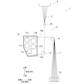
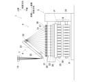
図1、図2に示すように、本実施形態に係る紡糸巻取機1(本発明の「糸処理設備」)は、延伸部3と引取部4と巻取部5とを備えている。引取部4および巻取部5は、延伸部3よりも下方に位置している。なお、以下では、図1、図2に示すように、鉛直方向、前後方向および左右方向を定義して説明を行う。鉛直方向は重力が作用する方向である。前後方向と左右方向と鉛直方向とは互いに直交する。また、以下では、図1、図2に示すように、鉛直方向の上側および下側と、左右方向の右側および左側と、前後方向の前側および後側を定義して説明を行う。
<Schematic configuration of spinning winder>
As shown in FIGS. 1 and 2, a yarn take-up
<延伸部>
図1に示すように、延伸部3は、上方にある紡糸装置2から、ポリエステル等の溶融繊維材料を連続的に紡出することによって生成された、複数の糸Yを延伸するものである。延伸部3は、給油ガイド10(本発明の「油剤塗布部」)と、5つのゴデットローラ11a~11eとを備えている。給油ガイド10は、紡糸装置2から紡出された複数の糸Yにそれぞれ油剤を付与するものである。
<Stretching part>
As shown in FIG. 1, the stretching
5つのゴデットローラ11a~11eは、軸方向が前後方向と平行なローラであり、図示しないモータによってそれぞれ回転駆動される。また、5つのゴデットローラ11a~11eは、それぞれ、金属などの導電性材料からなり、内部にヒータを有する。5つのゴデットローラ11a~11eは、直方体形状の保温箱12内に収容されている。保温箱12の右側壁部には、複数の糸Yを保温箱12内に導入するための糸導入口12aと、複数の糸Yを保温箱12内から外部へ導出するための糸導出口12bとが形成されている。
The five
給油ガイド10において油剤が付与された複数の糸Yは、案内ローラ13を経て、糸導入口12aから保温箱12内へ案内される。案内ローラ13は、軸方向が前後方向と平行なローラであり、金属などの導電性材料からなる。保温箱12内に導入された複数の糸Yは、5つのゴデットローラ11a~11eに対して、順に巻き掛けられている。
The plurality of threads Y to which the lubricant has been applied in the
上流側3つのゴデットローラ11a~11cは、複数の糸Yを延伸する前に予熱するための加熱ローラである。ゴデットローラ11a~11cの表面温度は、糸Yのガラス転移温度以上の温度に設定されている。
The three
下流側2つのゴデットローラ11d、11eは、延伸された複数の糸Yを熱セットするための加熱ローラである。ゴデットローラ11d、11eの表面温度は、上流側3つのゴデットローラ11a~11cの表面温度よりも高い温度に設定されている。また、下流側2つのゴデットローラ11d、11eの表面速度は、上流側3つのゴデットローラ11a~11cの表面速度よりも速くなっている。
The two
糸導入口12aから保温箱12内に導入された複数の糸Yは、まず、上流側3つのゴデットローラ11a~11cによって送られる間に、延伸可能な温度、すなわち、ガラス転移温度以上の温度まで予熱される、次に、予熱された複数の糸Yは、ゴデットローラ11cとゴデットローラ11dと表面速度の差によって延伸される。さらに、複数の糸Yは、下流側2つのゴデットローラ11d、11eによって送られる間により高温に加熱されて、延伸された状態が熱セットされる。上記のようにして延伸された複数の糸Yは、糸導出口12bから保温箱12外に導出され、さらに、案内ローラ14によって引取部4に送られる。案内ローラ14は、軸方向が前後方向と平行なローラであり、金属などの導電性材料からなる。
The plurality of yarns Y introduced into the
図2に示すように、引取部4は、ゴデットローラ21と、ゴデットローラ22とを備えている。
As shown in FIG. 2, the take-up
ゴデットローラ21は、軸方向が左右方向と平行なローラであり、案内ローラ14の下方に位置している。案内ローラ14によって引取部4に送られる複数の糸Yは、ゴデットローラ21によって引き取られる。ゴデットローラ21は、図示しないモータによって駆動される。
The
ゴデットローラ22は、軸方向が左右方向と平行なローラであり、ゴデットローラ21よりも後側に配置されている。ゴデットローラ22は、図示しないモータによって駆動される。また、引取部4は、前後方向における後側にいくほど、鉛直方向における上側に位置するように延びたガイドレール23を備えている。ゴデットローラ22は、図示しないプーリ、ベルトなどを介して図示しないモータに接続されている。このモータを駆動させると、ゴデットローラ22は、ガイドレール23に沿って移動する。これにより、ゴデットローラ22は、図2に実線で示す、糸Yの巻取を行うときの後側の位置と、図2に一点鎖線で示す、糸掛けを行うときの、ゴデットローラ21に近接する前側の位置との間で移動可能となっている。
The
<巻取部>
巻取部5は、複数のトラバース装置30と、ターレット33と、2本のボビンホルダ34と、コンタクトローラ35と、巻付検出部36とを備えている。複数のトラバース装置30は、複数の糸Yに対して個別に設けられ、前後方向に配列されている。各トラバース装置30は、支点ガイド31(本発明の「静止ガイド」)とトラバースガイド32(本発明の「移動ガイド」)とを有する。
<Take-up section>
The winding
支点ガイド31は、金属などの導電性材料からなる。複数のトラバース装置30の複数の支点ガイド31は、複数のスライダ37に取り付けられている。複数のスライダ37は、前後方向に延びたガイドレール38に沿って前後方向に移動可能に支持されている。また、複数のスライダ37は、図示しないシリンダに接続されている。シリンダを駆動させると、複数のスライダ37は、ガイドレール38に沿って前後方向に移動する。これにより、複数の支点ガイド31を、糸Yの巻取を行うときの前後方向に互いに離れた位置と、糸掛けを行うときの、前側に寄せられた位置との間で移動可能となっている。
The
トラバースガイド32は、金属などの導電性材料からなり、支点ガイド31よりも糸Yの走行方向における下流側に配置されている。トラバースガイド32は、図示しないモータによって駆動されて、前後方向に往復移動する。これにより、トラバースガイド32に掛けられた糸Yが、トラバースガイド32よりも糸Yの走行方向の上流側に位置する支点ガイド31を中心にトラバースされる。
The
ターレット33は、軸方向が前後方向と平行な円板状の部材である。ターレット33は図示しないモータによって回転駆動される。2本のボビンホルダ34は、それぞれ、軸方向が前後方向と平行であり、ターレット33の上端部及び下端部に回転自在に支持されている。各ボビンホルダ34には、複数の糸Yに対して個別に設けられた複数のボビンBが前後方向に並べて装着されている。また、2つのボビンホルダ34は、それぞれ、図示しないモータによって個別に駆動される。
The
そして、上側のボビンホルダ34を回転駆動させると、トラバースガイド32によってトラバースされた糸YがボビンBに巻き取られてパッケージPが形成される。また、パッケージPの形成が完了した後には、ターレット33を回転させることにより、2本のボビンホルダ34の上下の位置を入れ換える。これにより、それまで下側に位置していたボビンホルダ34が上側に移動し、このボビンホルダ34に装着されたボビンBに糸Yを巻き取ってパッケージPを形成することができる。また、それまで上側に位置していたボビンホルダ34が下側に移動し、パッケージPの回収が可能となる。
Then, when the
コンタクトローラ35は、軸方向が前後方向と平行なローラであり、金属などの導電性材料からなる。コンタクトローラ35は、上側のボビンホルダ34のすぐ上方に配置されている。コンタクトローラ35は、上側のボビンホルダ34に装着されたボビンBに糸Yが巻き取られた複数のパッケージPの表面の糸Yに接触することで、巻取中のパッケージPの表面に接圧を付与する。
The
巻付検出部36は、コンタクトローラ35のすぐ上方に位置している。巻付検出部36は、コンタクトローラ35への糸Yの巻き付きを検出する。
The winding
<充電部の構成>
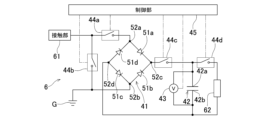
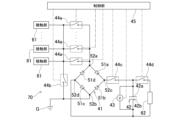
また、本実施形態の紡糸巻取機1は、図3に示す充電部6を備えている。充電部6は、全波整流回路41(本発明の「電圧印可回路」)と、コンデンサ42(本発明の「蓄電装置」)と、電圧検出回路43(本発明の「満充電検出部」)と、スイッチ44a~44dと、制御部45を有する。なお、本実施形態では、スイッチ44dが、本発明の「第1切換部」に相当し、スイッチ44a~44cと制御部45とを合わせたものが、本発明の「第2切換部」に相当する。
<Configuration of charging part>
Further, the
ここで、充電部6の各構成について詳細に説明する前に、図3の接触部61について説明する。接触部61は、紡糸巻取機1における、導電性を有し、走行する糸Yと接触する部分である。具体的には、接触部61は、例えば、ゴデットローラ11a~11e、案内ローラ13、14、ゴデットローラ21、22、コンタクトローラ35、支点ガイド31、およびトラバースガイド32のうちのいずれかである。走行する糸Yと接触部61との摩擦により、接触部61に静電気が発生する。
Here, before explaining each configuration of the
全波整流回路41は、4つのダイオード51a~51dを有する。ダイオード51aとカソードとダイオード51bのカソードとが接続されている。ダイオード51bのアノードとダイオード51cのカソードとが接続されている。ダイオード51cのアノードとダイオード51dのアノードとが接続されている。ダイオード51dのカソードとダイオード51aのアノードとが接続されている。
Full-
ダイオード51dのカソードとダイオード51aのアノードとの接続部52aは、接触部61と接続されている。また、接続部52aと接触部61との間には、スイッチ44aが接続されている。スイッチ44aは、制御部45の制御によりオンとオフが切り換えられる。スイッチ44aがオンの状態で、接続部52aと接触部61とが接続される。スイッチ44aがオフの状態で、接続部52aと接触部61との接続が遮断される。
A connecting
ダイオード51bのアノードとダイオード51cのカソードとの接続部52bは、接地部Gに接続されることによって接地されている。また、接触部61は、スイッチ44bを介して接地部Gに接続されている。スイッチ44bは、制御部45の制御によりオンとオフが切り換えられる。スイッチ44bがオンの状態で、接触部61が接地部Gに接続されることによって接地される。スイッチ44bがオフの状態で、接触部61の接地部Gとの接続が解除される。
A connecting
コンデンサ42は、ダイオード51aのカソードとダイオード51bのカソードとの接続部52cと、ダイオード51cのアノードとダイオード51dのアノードとの接続部52dとの間に接続されている。コンデンサ42は、接続部52cに接続される第1端子42aと、接続部52dに接続される第2端子42bとを有する。また、接続部52cとコンデンサ42の第1端子42aとの間には、スイッチ44cが接続されている。スイッチ44cは、制御部45の制御によりオンとオフが切り換えられる。スイッチ44cがオンの状態で、接続部52cがコンデンサ42の第1端子42aと接続される。スイッチ44cがオフの状態で、接続部52cとコンデンサ42の第1端子42aとの接続が遮断される。
The
また、コンデンサ42の第1端子42aおよび第2端子42bは、電動装置62と接続されている。電動装置62は、例えば、糸の張力センサ、接触部61において発生した静電気量を検出するセンサ、軸受の温度センサ等である。また、第1端子42aと電動装置62との間には、スイッチ44dが接続されている。スイッチ44dは、制御部45の制御によりオンとオフが切り換えられる。スイッチ44dがオンの状態で、コンデンサ42の第1端子42aが電動装置62に接続される。スイッチ44dがオフの状態で、コンデンサ42の第1端子42aの電動装置62との接続が遮断される。
Further, the
電圧検出回路43は、コンデンサ42の第1端子42aと第2端子42bとの間に接続されている。電圧検出回路43は、第1端子42aと第2端子42bとの間の電圧を示す信号を制御部45に出力する。制御部45は、電圧検出回路43から出力される信号が示す電圧が所定電圧以上のときに、この信号をコンデンサ42が満充電されていることを示す信号として受信する。また、制御部45は、電圧検出回路43から出力される信号が示す電圧が所定電圧未満のときに、この信号をコンデンサ42が満充電されていないことを示す信号として受信する。
The
ここで、接触部61と充電部6の各部分との接続について説明する。接触部61が支点ガイド31である場合、支点ガイド31と充電部6とは、例えば配線によって接続される。また、接触部61がトラバースガイド32である場合、例えば、トラバースガイド32を支持する部材と充電部6とが配線によって接続されることによって、トラバースガイド32と充電部6とが接続される。また、接触部61がゴデットローラ11a~11e、案内ローラ13、14、ゴデットローラ21、22およびコンタクトローラ35のいずれかのローラである場合、例えば、充電部6に接続された除電ブラシをローラに接触させることによって、ローラと充電部6とが接続される。あるいは、接触部61が上記いずれかのローラである場合、例えば、充電部6に接続された電極をローラと離間させて対向させることによってローラから電極への放電が可能となっていてもよい。この場合でも、ローラと充電部6とは電気的に接続されている。
Here, the connection between the
<充電部の動作>
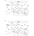
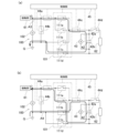
次に、充電部6の動作について説明する。充電部6では、電圧検出回路43から出力される信号が示す電圧が所定電圧未満である(コンデンサ42が満充電されていない)ときに、図4(a)、(b)に示すように、制御部45が、スイッチ44a、44cをオンにし、スイッチ44b、44dをオフにする。これにより、接触部61で発生した静電気の電荷によってコンデンサ42が充電され、接触部61で発生した静電気が除去される。
<Operation of charging part>
Next, the operation of charging
より詳細に説明すると、接触部61に発生した静電気の電荷が正の電荷である場合、図4(a)に示すように、接触部61、スイッチ44a、接続部52a、ダイオード51a、接続部52c、スイッチ44c、コンデンサ42、接続部52d、ダイオード51c、接続部52bおよび接地部Gをこの順に通る経路(図4(a)に矢印A1で示す経路)に沿って、電流が流れる。これにより、接触部61で発生した電荷によってコンデンサ42が充電され、接触部61で発生した静電気が除去される。
To explain in more detail, when the static electricity generated in the
接触部61に発生した静電気の電荷が負の電荷である場合、図4(b)に示すように、接地部G、接続部52b、ダイオード51b、接続部52c、スイッチ44c、コンデンサ42、接続部52d、ダイオード51d、接続部52a、スイッチ44aおよび接触部61をこの順に通る経路(図4(b)に矢印A2で示す経路)に沿って、電流が流れる。これにより、接触部61で発生した電荷によってコンデンサ42が充電され、接触部61で発生した静電気が除去される。
When the static electricity generated in the
ここで、上述したように、接触部61に発生した静電気の電荷が、正の電荷および負の電荷のいずれである場合にも、コンデンサ42の第1端子42aが第2端子42bよりも高電位となり、コンデンサ42が充電される。
Here, as described above, regardless of whether the static electricity generated in the
また、充電部6では、電圧検出回路43から出力される信号が示す電圧が所定電圧以上である(コンデンサ42が満充電されている)ときに、図5(a)に示すように、制御部45が、スイッチ44bをオンにし、スイッチ44a、44c、44dをオフにする。これにより、接触部61が接地部Gに接続されることによって接地され、接触部61で発生した静電気が除去される。
In addition, in the
また、充電部6では、電動装置62を駆動させるときに、図5(b)に示すように、制御部45が、スイッチ44b、44dをオンにし、スイッチ44a、44cをオフにする。これにより、コンデンサ42と電動装置62とが接続され、コンデンサ42に充電された電荷によって、電動装置62を駆動させることができる。このように、本実施形態では、コンデンサ42に充電された電荷によって電動装置62を駆動させることができるため、電動装置62を紡糸巻取機の電源に接続する必要がなく、必要に応じて簡単に取り付けて駆動させることができる。また、このとき、スイッチ44bをオンにするため、接触部61が接地部Gに接続されることによって接地される。これにより、電動装置62が駆動されている間に接触部61に静電気による電荷が溜まり続けないようにすることができる。ただし、電動装置62を駆動させる時間が短時間であり、電動装置62が駆動されている間に接触部61に静電気によって溜まる電荷がそれほど大きくならない場合には、スイッチ44bをオフにしてもよい。
Further, in the
<効果>
本実施形態では、スイッチ44dをオフにした状態で、走行する糸Yと接触部61との摩擦によって接触部61に発生した静電気の電荷によってコンデンサ42を充電することができる。ここで、糸Yの種類、糸Yに塗布される油剤の種類、糸Yに塗布される油剤の銘柄、湿度などの周囲の環境の変化等によって、油剤が塗布された糸Yと接触部61との摩擦によって接触部61に発生する静電気の極性が変わる。そこで、本実施形態では、接触部61とコンデンサ42との間に全波整流回路41を接続することにより、接触部61に発生した静電気の電荷によって第1端子42aと第2端子42bとの間に電圧が印加されるときに、接触部61に発生した静電気の極性によらず、コンデンサ42の第1端子42aが第2端子42bよりも高電位となるようにする。これにより、接触部61に発生する静電気の極性によらずコンデンサ42を充電させることができ、コンデンサ42を効率よく充電することができる。そして、接触部61に発生した静電気の電荷によってコンデンサ42が充電されることで、接触部61に発生する静電気を除去することができる。
<Effect>
In this embodiment, with the
また、電動装置62を駆動させる必要があるときに、コンデンサ42が充電された状態でスイッチ44dをオンにして、コンデンサ42の第1端子42aと電動装置62とを接続することにより、コンデンサ42に充電された電荷を利用して電動装置62を駆動させることができる。
Further, when it is necessary to drive the
また、一般に、走行する糸YをボビンBに巻き取ってパッケージPを形成する紡糸巻取機1では、糸Yの走行速度が速い。そのため、走行する糸Yと接触部61との摩擦が大きく、接触部61に発生する静電気が大きい。本実施形態では、糸Yの走行速度が速い紡糸巻取機1の接触部61に発生した静電気の電荷によってコンデンサ42を充電するため、コンデンサ42を効率よく充電することができる。また、コンデンサ42を充電することによって、接触部61に発生する大きな静電気を除去することができる。
Further, in general, in the yarn take-up
複数の糸Yを搬送するゴデットローラ11a~11e、案内ローラ13、14およびゴデットローラ21、22では、複数の糸Yの各々との摩擦によってそれぞれ静電気が発生するため、発生する静電気の総量が大きい。したがって、これらのローラのいずれかを接触部61として、このローラに発生した静電気の電荷によってコンデンサ42を充電する場合には、コンデンサ42を効率よく充電することができる。また、コンデンサ42を充電することによって、このローラに発生する大きな静電気を除去することができる。
In the
また、複数の糸Yを搬送するゴデットローラ11a~11e、案内ローラ13、14およびゴデットローラ21、22は、糸Yをグリップしつつ糸Yを搬送する。そして、これらのローラのうちのいずれかのローラの回転速度を調整することによって、走行する糸Yの張力を調整することがある。本実施形態では、当該ローラに発生した静電気の電荷によるコンデンサ42の充電量に基づいて、当該ローラによる糸Yのグリップの程度、言い換えれば、当該ローラと糸Yとのスリップの程度を検出することができる。
Further, the
また、コンタクトローラ35は巻き取り中のパッケージPの表面に位置する糸Yと接触しながら回転するため、コンタクトローラ35には静電気が発生する。また、本実施形態の場合、コンタクトローラ35は、複数のパッケージPの表面に位置する糸Yと接触しながら回転するため、発生する静電気の総量が大きい。したがって、コンタクトローラ35を接触部61として、コンタクトローラ35に発生した静電気の電荷によってコンデンサ42を充電する場合には、コンデンサ42を効率よく充電することができる。また、コンデンサ42を充電することによって、コンタクトローラ35に発生する静電気を除去することができる。
Further, since the
また、コンタクトローラ35への糸Yの巻き付きを検出する巻付検出部36は、コンタクトローラ35と近接して配置されるため、コンタクトローラ35に静電気が発生したときに、コンタクトローラ35と巻付検出部36との間で放電が発生しやすい。したがって、コンタクトローラ35を接触部61として、コンタクトローラ35に発生した静電気の電荷によってコンデンサ42を充電する場合には、コンタクトローラ35の静電気を除去することによって、コンタクトローラ35と巻付検出部36との間での放電を抑えることができる。
Further, since the winding
トラバース装置30のトラバースガイド32は、走行する糸Yとの摩擦によって静電気が発生する。したがって、トラバースガイド32を接触部61として、トラバースガイド32に発生した静電気の電荷でコンデンサ42を充電する場合には、トラバースガイド32に発生した静電気を除去することができる。
The
トラバース装置30の支点ガイド31は、走行する糸Yとの摩擦によって静電気が発生する。また、支点ガイド31は綾振りの支点であるため、他の固定ガイドと比較して糸Yの屈曲角度が大きく、発生する静電気が大きい。したがって、支点ガイド31を接触部61として、支点ガイド31に発生した静電気の電荷でコンデンサ42を充電する場合には、支点ガイド31に発生した大きな静電気を除去し、コンデンサ42を効率よく充電することができる。また、本実施形態では、支点ガイド31が複数の糸Yに対して個別のものである。これにより、支点ガイド31に発生する静電気によってコンデンサ42が充電されるか否か(支点ガイド31に静電気が発生しているか否か)に基づいて、糸切れを検出することができる。
Static electricity is generated in the
また、支点ガイド31は、糸Yの走行に合わせて移動しないため、糸Yの走行に合わせて回転するゴデットローラ11a~11e、案内ローラ13、14、ゴデットローラ21、22、コンタクトローラ35などと比較して、走行する糸Yとの摩擦が大きく、発生する静電気が大きい。したがって、支点ガイド31を接触部61として、支点ガイド31に発生した静電気の電荷によってコンデンサ42を充電する場合には、コンデンサ42を効率よく充電することができる。また、コンデンサ42を充電することによって、支点ガイド31に発生する大きな静電気を除去することができる。
Furthermore, since the
また、本実施形態では、接触部61が、ゴデットローラ11a~11e、案内ローラ13、14、ゴデットローラ21、22、コンタクトローラ35、支点ガイド31、およびトラバースガイド32のうちのいずれである場合にも、糸Yの走行方向における接触部61よりも上流側に給油ガイド10が配置されることになる。給油ガイド10において糸Yに塗布される油剤の銘柄、油剤の種類、湿度などの周囲の環境の変化等によって、油剤が塗布された糸Yと接触部61との摩擦によって接触部61で発生する静電気の極性が変わることがある。本実施形態では、接触部61とコンデンサ42との間に全波整流回路41を接続することによって、接触部61に発生した静電気の電荷によってコンデンサ42の第1端子42aと第2端子42bとの間に電圧が印加されるときに、接触部61に発生した静電気の極性によらず、第1端子42aが第2端子42bよりも高電位となるようにする。これにより、糸Yに塗布される油剤の付着の程度のばらつきによって接触部61で発生する静電気の極性が変わっても、コンデンサ42への充電を継続させることができる。
Further, in this embodiment, even when the
また、本実施形態では、コンデンサ42が満充電されていない状態では、接触部61を全波整流回路41に接続することにより、接触部61に発生した静電気の電荷によってコンデンサ42を充電することができる。一方、コンデンサ42が満充電された状態では、接触部61を接地させることにより、接触部61に発生した静電気を外部に逃がすことができる。
Furthermore, in this embodiment, when the
以上、本発明の好適な実施形態について説明したが、本発明は、上述の実施形態に限られるものではなく、特許請求の範囲に記載の限りにおいて様々な変更が可能である。 Although the preferred embodiments of the present invention have been described above, the present invention is not limited to the above-described embodiments, and various modifications can be made within the scope of the claims.
例えば、上述の実施形態では、1つの接触部61で発生した静電気の電荷によって1つのコンデンサ42を充電したが、これには限られない。
For example, in the embodiment described above, one
例えば、ゴデットローラ11a~11e、案内ローラ13、14、ゴデットローラ21、22、コンタクトローラ35、支点ガイド31、およびトラバースガイド32のうち2つ以上をそれぞれ接触部61とし、接触部61毎に個別に、上述の実施形態と同様の充電部6を設けてもよい。
For example, two or more of the
また、接触部61が複数ある場合に、接触部61毎に個別に充電部6を設けることにも限られない。変形例1では、図6に示すように、充電部70において、接続部52aに複数の接触部61が並列に接続されている。複数の接触部61は、それぞれ、ゴデットローラ11a~11e、案内ローラ13、14、ゴデットローラ21、22、コンタクトローラ35、支点ガイド31、およびトラバースガイド32のうちのいずれかである。また、接続部52aと各接触部61と間に、それぞれ、スイッチ44aが接続されている。
Moreover, when there are a plurality of
変形例1の場合には、電圧検出回路43から出力される信号が示す電圧が所定電圧未満のときに、制御部45が、複数のスイッチ44aのうち1つのスイッチ44aと、スイッチ44cとをオンにし、複数のスイッチ44aのうち上記1つのスイッチ44a以外のスイッチ44aと、スイッチ44b、44dとをオフにする。また、このとき、制御部45は、例えば、一定時間毎に複数のスイッチ44aのうちオンにする1つのスイッチ44aを切り換える。
In the case of
変形例1の場合には、複数の接触部61で発生した静電気の電荷によって、コンデンサ42を充電し、コンデンサ42の充電によって複数の接触部61で発生した静電気を除去することができる。
In the case of the first modification, the
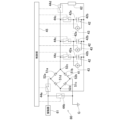
変形例2では、図7に示すように、充電部80において、接続部52cと接続部52dとの間に、複数のコンデンサ42が並列に接続されている。また、接続部52cと各コンデンサ42の第1端子42aと間に、それぞれ、スイッチ44cが接続されている。また、各コンデンサ42の第1端子42aと第2端子42bとの間に電圧検出回路43が接続されている。
In
変形例2の場合には、1つ以上の電圧検出回路43から出力される信号が示す電圧が所定電圧未満である(満充電されていないコンデンサ42がある)ときに、制御部45が、スイッチ44aと、上記1つ以上の電圧検出回路43に対応する1つ以上のスイッチ44cのうち1つのスイッチ44cとをオンにし、スイッチ44b、44dと、複数のスイッチ44cのうち上記1つのスイッチ44c以外のスイッチ44cをオフにする。また、あるスイッチ44cをオンにした後、このスイッチ44cに対応する電圧検出回路43から出力される信号が示す電圧が所定電圧以上となった(このスイッチ44cに対応するコンデンサ42が満充電となった)ときに、このスイッチ44cをオフにする。さらに、別の電圧検出回路43から出力される信号が示す電圧が所定電圧未満である(満充電されていない別のコンデンサ42がある)場合には、当該別の電圧検出回路43に対応するスイッチ44cをオンにする。
In the case of
一方、すべての電圧検出回路43が出力する信号が示す電圧が所定電圧以上である(すべてのコンデンサ42が満充電されている)場合には、スイッチ44a、44dと複数のスイッチ44cとをオフにし、スイッチ44bをオンにする。また、変形例2の場合には、複数のスイッチ44cのうち1つのスイッチ44cとスイッチ44b、44dとをオンにし、スイッチ44aと複数のスイッチ44cのうち上記1つのスイッチ44c以外のスイッチ44cをオフにすることにより、上記1つのスイッチ44cに対応するコンデンサ42に充電された電荷により電動装置62を駆動させることができる。
On the other hand, when the voltages indicated by the signals output by all the
変形例2の場合には、接触部61で発生した静電気の電荷によって複数のコンデンサ42を充電することができる。そして、これら複数のコンデンサ42に充電された電荷によって電動装置62を駆動させることができる。
In the case of the second modification, the plurality of
また、充電部において、変形例1と同様に、複数の接触部61と複数のスイッチ44aが設けられているのに加えて、変形例2と同様に、複数のコンデンサ42と複数のスイッチ44cと複数の電圧検出回路43が設けられていてもよい。この場合には、複数の接触部61で発生した電荷によって複数のコンデンサ42を充電し、複数のコンデンサ42に充電された電荷によって電動装置62を駆動させることができる。
Further, in the charging section, in addition to the plurality of
また、上述の実施形態では、接触部61とコンデンサ42との間に全波整流回路41を接続することによって、接触部61で発生した静電気の電荷によって、静電気の極性によらず、第1端子42aが第2端子42bよりも高電位となるように第1端子42aと第2端子42bとの間に電圧を印加させたが、これには限られない。接触部61とコンデンサ42との間に全波整流回路41とは別の電圧印可回路を接続することによって、接触部61で発生した静電気の電荷によって、静電気の極性によらず、第1端子42aが第2端子42bよりも高電位となるように第1端子42aと第2端子42bとの間に電圧を印加させるようにしてもよい。
Furthermore, in the above-described embodiment, by connecting the full-
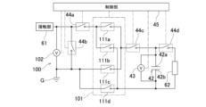
例えば、変形例3では、図8に示すように、充電部100が、上述の実施形態の充電部6における全波整流回路41の代わりに、電圧印可回路101を備えている。また、充電部100が電圧検出回路102を備えている。
For example, in
電圧印可回路101は、4つのスイッチ111a~111dを有する。スイッチ111aは、スイッチ44aの接触部61と反対側の端子と、スイッチ44cのコンデンサ42と反対側の端子との間に接続されている。スイッチ111bは、スイッチ44aの接触部61と反対側の端子と、コンデンサ42の第2端子42bとの間に接続されている。スイッチ111cはスイッチ44cのコンデンサ42と反対側の端子と接地部Gとの間に接続されている。スイッチ111dは、コンデンサ42の第2端子42bと、接地部Gとの間に接続されている。また、スイッチ111a~111dは、制御部45によってオンとオフとが切り換えられる。なお、変形例3では、スイッチ44dが、本発明の「第1切換部」に相当し、スイッチ44a~44c、111a~111dと制御部45とを合わせたものが、本発明の「第2切換部」に相当する。
電圧検出回路102は、接触部61と接地部Gとの間に接続され、接地部Gの電位(グランド電位)を基準とする接触部61の電位を示す信号を制御部45に出力する。接触部61に発生した静電気の電荷が正の電荷である場合、電圧検出回路102から出力される信号は、グランド電位よりも高い正の電位を示すものとなる。接触部61に発生した静電気の電荷が負の電荷である場合、電圧検出回路102から出力される信号は、グランド電位よりも低い負の電位を示すものとなる。
The
変形例3では、電圧検出回路43から出力される信号が示す電圧が所定電圧未満のとき(コンデンサ42が満充電されていないとき)に、図9(a)、(b)に示すように、制御部45が、スイッチ44a、44cをオンにし、スイッチ44b、44dをオフにする。
In
さらに、電圧検出回路102から出力される信号が正の電位を示すものであるとき、すなわち、接触部61で発生した静電気の電荷が正の電荷であるときに、図9(a)に示すように、制御部45が、スイッチ111a、111dをオンにし、スイッチ111b、111cをオフにする。すると、接触部61、スイッチ44a、スイッチ111a、スイッチ44c、コンデンサ42、スイッチ111d、および接地部Gをこの順に通る経路(図9(a)に矢印A3で示す経路)に沿って、電流が流れる。これにより、接触部61で発生した静電気が除去されるとともに、接触部61で発生した静電気の電荷によってコンデンサ42が充電される。
Furthermore, when the signal output from the
一方、電圧検出回路102から出力される信号が負の電位を示すとき、すなわち、接触部61で発生した静電気の電荷が負の電荷であるときに、図9(b)に示すように、制御部45が、スイッチ111b、111cをオンにし、スイッチ111a、111dをオフにする。すると、接地部G、スイッチ111c、スイッチ44c、コンデンサ42、スイッチ111b、スイッチ44a、および接触部61をこの順に通る経路(図9(b)に矢印A4で示す経路)に沿って、電流が流れる。これにより、接触部61で発生した静電気が除去されるとともに、接触部61で発生した静電気の電荷によってコンデンサ42が充電される。
On the other hand, when the signal output from the
そして、変形例3の場合でも、接触部61に発生した静電気の極性によらず、コンデンサ42の第1端子42aが第2端子42bよりも高電位となる。
Even in the case of the third modification, the
また、上述の実施形態では、スイッチ44a~44dのオンオフを制御部45の制御によって切り換えたがこれには限られない。例えば、充電部6が、スイッチ44a~44dの少なくとも一部についてオンとオフを切り換える回路を有していてもよい。
Further, in the above-described embodiment, the
例えば、充電部6が充電制御用のICを有し、このICにより、コンデンサ42が満充電されているか否かに応じて、スイッチ44a~44dの図4(a)、(b)の状態と、図5(a)の状態とが切り換えられるようになっていてもよい。
For example, the charging
また、上述の実施形態では、電圧検出回路43から出力される信号が示す電圧が所定電圧以上である(コンデンサ42が満充電されている)ときに、接触部61を接地部Gと接続させることによって接地したが、これには限られない。電圧検出回路43から出力される信号が示す電圧が所定電圧以上であるときに、スイッチ44a、44cをオフにし、かつ、接触部61を接地させなくてもよい。
Furthermore, in the embodiment described above, when the voltage indicated by the signal output from the
また、上述の実施形態では、紡糸巻取機1がコンタクトローラ35への糸Yの巻き付きを検出するための巻付検出部36を備えていたが、紡糸巻取機1は、巻付検出部36を備えていなくてもよい。
Further, in the above-described embodiment, the yarn take-up
また、上述の実施形態では、接触部61が、ゴデットローラ11a~11e、案内ローラ13、14、ゴデットローラ21、22、コンタクトローラ35、支点ガイド31、およびトラバースガイド32のいずれかであったが、これには限られない。例えば、紡糸巻取機1が、接触部61として、導電性を有し、走行する糸Yと接触する別の部分を備えていてもよい。また、この場合、接触部61が、支点ガイド31以外の静止ガイドであってもよい。
Further, in the above embodiment, the
また、上述の実施形態では、紡糸巻取機1が給油ガイド10を備えており、接触部61が、糸Yの走行方向において給油ガイド10よりも下流側に位置する部材であったが、これには限られない。例えば、紡糸巻取機1が、糸の走行方向において、給油ガイド10よりも上流側に、接触部61として、導電性材料を有し、走行する糸Yと接触する別の部分を備えていてもよい。あるいは、紡糸巻取機1が給油ガイド10を備えていなくてもよい。
Further, in the above-described embodiment, the
また、以上の例では、接触部61で発生した静電気の電荷によりコンデンサ42に充電したが、これには限られない。例えば、コンデンサ42の代わりにバッテリーを設け、接触部61で発生した静電気の電荷でこのバッテリーを充電してもよい。この場合には、バッテリーが本発明の「蓄電装置」に相当する。
Further, in the above example, the
また、以上では、走行する糸Yを巻き取ってパッケージを形成する紡糸巻取機に本発明を適用した例について説明したが、これには限られない。紡糸巻取機以外の糸処理設備に本発明を適用することも可能である。 Moreover, although the example in which the present invention is applied to a spinning winder that winds the traveling yarn Y to form a package has been described above, the present invention is not limited thereto. It is also possible to apply the present invention to yarn processing equipment other than spinners.
また、以上では、糸処理設備が備えるコンデンサなどに充電された電荷によって、糸処理設備を構成する電動装置を駆動させる例について説明したが、これには限られない。 Moreover, although an example has been described above in which an electric device constituting the yarn processing equipment is driven by an electric charge charged in a capacitor or the like provided in the yarn processing equipment, the present invention is not limited to this.
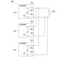
変形例4では、図10に示すように、糸処理設備システム200が、複数の糸処理設備201と、1つの電動装置202とを備えている。複数の糸処理設備201は、それぞれ、例えば上述の実施形態の紡糸巻取機1から電動装置62を除いたものである。複数の糸処理設備201は、例えば、同じ建物内に設置されたものである。また、複数の糸処理設備201は同じ種類の設備であってもよいし、異なる種類の設備であってもよい。なお、図10では、糸処理設備システム200が3つの糸処理設備201を備える場合を示しているが、糸処理設備システム200を構成する糸処理設備201の数は、2つまたは4つ以上であってもよい。また、図10では、糸処理設備201のうち、コンデンサ42およびスイッチ44d以外の構成については図示を省略している。
In
電動装置202は、例えば、糸処理設備201が設置されている建物とは別の建物に設置された装置など、糸処理設備201を構成する装置とは別の装置である。
The
糸処理設備システム200では、各糸処理設備201のコンデンサ42の第1端子42aがスイッチ44dを介して電動装置202の一方の端子に接続され、各糸処理設備201のコンデンサ42の第2端子42bが電動装置202の他方の端子に接続されている。そして、各糸処理設備201のコンデンサ42が充電された状態で、当該糸処理設備201のスイッチ44dをオンにすると、当該コンデンサ42に充電された電荷により、電動装置202が駆動される。すなわち、変形例4では、複数の糸処理設備201のコンデンサ42に充電された電荷によって電動装置202が駆動される。なお、変形例4では、スイッチ44dが本発明の「切換部」に相当する。
In the yarn
変形例4でも、上述の実施形態で説明したのと同様、各糸処理設備201において、スイッチ44dをオフにした状態で、走行する糸Yと接触部との摩擦によって接触部に発生した静電気の電荷によって、接触部に発生した静電気の極性によらず、コンデンサ42を充電することができる。そして、接触部に発生した静電気の電荷によってコンデンサ42が充電されることで、接触部に発生した静電気を除去することができる。
In the fourth modification, as described in the above embodiment, in each
また、変形例4では、電動装置202を駆動させる必要があるときに、コンデンサ42が充電された状態でスイッチ44dをオンにすることにより、コンデンサ42に充電された電荷を利用して電動装置202を駆動させることができる。
In addition, in the fourth modification, when it is necessary to drive the
また、変形例4では、複数の糸処理設備201のコンデンサ42に充電された電荷を利用して1つの電動装置202を駆動させるため、各糸処理設備201のコンデンサ42に充電された電荷量がそれほど大きくなくても、これらの電荷量の合計がある程度大きければ、電動装置202を駆動させることができる。
In addition, in the fourth modification, since one
変形例4では、糸処理設備システム200が、複数の糸処理設備201と1つの電源装置202とを備え、複数の糸処理設備201のコンデンサ42に充電された電荷によって1つの電動装置202が駆動されていたが、これには限られない。糸処理設備システムが、1つの糸処理設備と、糸処理設備の外部に設けられた1つの電動装置とによって構成され、1つの糸処理設備のコンデンサ42に充電された電荷によって1つの電動装置が駆動されてもよい。
In
また、以上の例では、スイッチ44dがコンデンサ42の第1端子42aと電動装置62、202との間に接続されていたが、これには限られない。スイッチ44dがコンデンサ42の第2端子42bと電動装置62、202との間に接続されていてもよい。
Further, in the above example, the
また、以上の例において、電動装置が、糸処理設備の蓄電装置に接続されているのに加えて、商用電源などの別の電源に接続されていてもよい。そして、糸処理設備の蓄電装置に充電された電荷と上記別の電源から供給される電荷とによって電動装置を駆動させてもよい。このとき、糸処理設備の蓄電装置に十分な電荷が充電されている場合には、蓄電装置に充電された電荷のみによって電動装置を駆動させてもよい。このように、糸処理設備の蓄電装置に充電された電荷と上記別の電源から供給される電荷とによって電動装置を駆動させる場合には、上記別の電源における消費電力を抑えることができるとともに、糸処理設備の蓄電装置から電動装置に十分な電荷を供給できないときにも電動装置を駆動させることができる。 Furthermore, in the above example, the electric device may be connected to another power source such as a commercial power source in addition to being connected to the power storage device of the yarn processing facility. Then, the electric device may be driven by the electric charge stored in the power storage device of the yarn processing equipment and the electric charge supplied from the above-mentioned separate power source. At this time, if the power storage device of the yarn processing equipment is charged with sufficient charge, the electric device may be driven only by the charge stored in the power storage device. In this way, when the electric device is driven by the charge charged in the electricity storage device of the yarn processing equipment and the charge supplied from the separate power source, the power consumption in the separate power source can be suppressed, and The electric device can be driven even when sufficient charge cannot be supplied to the electric device from the power storage device of the yarn processing equipment.
1:紡糸巻取機(糸処理設備)
5:巻取部
10:給油ガイド(油剤塗布部)
11a~11e:ゴデットローラ(搬送ローラ)
13、14:案内ローラ(搬送ローラ)
21、22:ゴデットローラ(搬送ローラ)
30:トラバース装置
31:支点ガイド(静止ガイド)
32:トラバース回路(移動ガイド)
35:コンタクトローラ
36:巻付検出部
41:全波整流回路(電圧印可回路)
42:コンデンサ(蓄電装置)
42a:第1端子
42b:第2端子
43:電圧検出回路(満充電検出部)
44a~44d:スイッチ(切換部、第1切換部、第2切換部)
45:制御部(切換部)
61:接触部
62:電動装置
101:電圧印可回路
200:糸処理設備システム
201:糸処理設備
202:電動装置
1: Spinning winder (yarn processing equipment)
5: Winding section 10: Lubrication guide (oil application section)
11a to 11e: Godet roller (conveyance roller)
13, 14: Guide roller (conveyance roller)
21, 22: Godet roller (conveyance roller)
30: Traverse device 31: Fulcrum guide (stationary guide)
32: Traverse circuit (movement guide)
35: Contact roller 36: Wrapping detection section 41: Full wave rectifier circuit (voltage application circuit)
42: Capacitor (power storage device)
42a: First terminal 42b: Second terminal 43: Voltage detection circuit (full charge detection section)
44a to 44d: Switch (switching section, first switching section, second switching section)
45: Control section (switching section)
61: Contact portion 62: Electric device 101: Voltage application circuit 200: Yarn processing equipment system 201: Yarn processing equipment 202: Electric device
Claims (11)
第1端子と第2端子とを有し、前記第1端子と前記第2端子との間に電圧を印加することによって充電可能な少なくとも1つの蓄電装置と、
前記接触部と前記蓄電装置との間に接続され、走行する糸と前記接触部との摩擦によって発生した静電気の電荷によって、前記静電気の極性によらず、前記第1端子が前記第2端子よりも高電位となるように前記第1端子と前記第2端子との間に電圧を印加する電圧印可回路と、
前記蓄電装置と接続される電動装置と、
前記蓄電装置の前記第1端子および前記第2端子のいずれかと前記電動装置との間に接続され、前記蓄電装置と前記電動装置との接続と、その遮断とを切り換える第1切換部と、を備えていることを特徴とする糸処理設備。 at least one contact portion that is electrically conductive and comes into contact with the running thread;
at least one power storage device that has a first terminal and a second terminal and is chargeable by applying a voltage between the first terminal and the second terminal;
Regardless of the polarity of the static electricity, the first terminal becomes closer to the second terminal due to static electricity generated by friction between the contact part and a running thread connected between the contact part and the power storage device. a voltage applying circuit that applies a voltage between the first terminal and the second terminal so that the voltage is at a high potential;
an electric device connected to the power storage device;
a first switching unit that is connected between either the first terminal or the second terminal of the power storage device and the electric device and switches between connection and disconnection between the power storage device and the electric device; Yarn processing equipment characterized by being equipped with.
前記巻取部が、
巻き取り中のパッケージの表面に位置する糸と接触する、前記接触部としてのコンタクトローラと、
前記コンタクトローラへの糸の巻き付きを検出する巻付検出部と、を有することを特徴とする請求項1~4のいずれかに記載の糸処理設備。 A winding section that winds the running thread onto a bobbin to form a package,
The winding section
a contact roller as the contact portion that contacts the yarn located on the surface of the package being wound;
The yarn processing equipment according to any one of claims 1 to 4, further comprising a winding detection section that detects winding of the yarn around the contact roller.
前記巻取部が、ボビンへの糸の巻き取り時に糸をボビンの軸方向に綾振りさせるトラバース装置、を有し、
前記トラバース装置が、
糸を保持してボビンの軸方向に往復移動する移動ガイドと、
前記移動ガイドよりも糸の走行方向の上流側において糸を支持する支点ガイドと、を有し、
前記移動ガイドが前記接触部であることを特徴とする請求項1~5のいずれかに記載の糸処理設備。 A winding section that winds the running thread onto a bobbin to form a package,
The winding unit includes a traverse device that traverses the thread in the axial direction of the bobbin when winding the thread onto the bobbin,
The traverse device includes:
a moving guide that holds the thread and moves it back and forth in the axial direction of the bobbin;
a fulcrum guide that supports the thread on the upstream side of the moving guide in the running direction of the thread;
The yarn processing equipment according to any one of claims 1 to 5, wherein the movement guide is the contact portion.
前記巻取部が、ボビンへの糸の巻き取り時に糸をボビンの軸方向に綾振りさせるトラバース装置、を有し、
前記トラバース装置が、
糸を保持してボビンの軸方向に往復移動する移動ガイドと、
前記移動ガイドよりも糸の走行方向の上流側において糸を支持する支点ガイドと、を有し、
前記支点ガイドが前記接触部であることを特徴とする請求項1~6のいずれかに記載の糸処理設備。 A winding section that winds the running thread onto a bobbin to form a package,
The winding unit includes a traverse device that traverses the thread in the axial direction of the bobbin when winding the thread onto the bobbin,
The traverse device includes:
a moving guide that holds the thread and moves it back and forth in the axial direction of the bobbin;
a fulcrum guide that supports the yarn upstream of the moving guide in the yarn running direction;
The yarn processing equipment according to any one of claims 1 to 6, wherein the fulcrum guide is the contact portion.
前記蓄電装置が満充電されているか否かを検出する満充電検出部と、を備え、
前記第2切換部は、
前記満充電検出部により前記蓄電装置が満充電されていないことが検出されているときに前記接触部を前記電圧印可回路に接続させ、
前記満充電検出部により前記蓄電装置が満充電されていることが検出されているときに前記接触部を接地させるように構成されていることを特徴とする請求項1~8のいずれかに記載の糸処理設備。 a second switching section that switches whether the contact section is connected to the voltage application circuit or grounded;
a full charge detection unit that detects whether the power storage device is fully charged;
The second switching section is
connecting the contact portion to the voltage application circuit when the full charge detection portion detects that the power storage device is not fully charged;
According to any one of claims 1 to 8, the contact portion is configured to be grounded when the full charge detection unit detects that the power storage device is fully charged. Yarn processing equipment.
前記糸処理設備が、
導電性を有し、走行する糸と接触する少なくとも1つの接触部と、
第1端子と第2端子とを有し、前記第1端子と前記第2端子との間に電圧を印加することによって充電可能な少なくとも1つの蓄電装置と、
前記接触部と前記蓄電装置との間に接続され、走行する糸と前記接触部との摩擦によって発生した静電気の電荷によって、前記静電気の極性によらず、前記第1端子が前記第2端子よりも高電位となるように前記第1端子と前記第2端子との間に電圧を印加する電圧印可回路と、
前記蓄電装置の前記第1端子および前記第2端子のいずれかと前記電動装置との間に接続され、前記蓄電装置と前記電動装置との接続とその遮断とを切り換える切換部と、を備えていることを特徴とする糸処理設備システム。 A yarn processing equipment system comprising yarn processing equipment and an electric device disposed outside the yarn processing equipment,
The yarn processing equipment
at least one contact portion that is electrically conductive and comes into contact with the running thread;
at least one power storage device that has a first terminal and a second terminal and is chargeable by applying a voltage between the first terminal and the second terminal;
Regardless of the polarity of the static electricity, the first terminal becomes closer to the second terminal due to static electricity generated by friction between the contact part and a running thread connected between the contact part and the power storage device. a voltage applying circuit that applies a voltage between the first terminal and the second terminal so that the voltage is at a high potential;
a switching unit connected between either the first terminal or the second terminal of the power storage device and the electric device and switching between connection and disconnection of the power storage device and the electric device; A yarn processing equipment system characterized by:
前記複数の糸処理設備と接続された1つの前記電動装置と、を備えていることを特徴とする請求項10に記載の糸処理設備システム。 a plurality of the yarn processing equipment;
The yarn processing equipment system according to claim 10, further comprising: one of the electric devices connected to the plurality of yarn processing equipment.
Applications Claiming Priority (2)
| Application Number | Priority Date | Filing Date | Title |
|---|---|---|---|
| JP2022131973 | 2022-08-22 | ||
| JP2022131973 | 2022-08-22 |
Publications (2)
| Publication Number | Publication Date |
|---|---|
| JP2024029748A true JP2024029748A (en) | 2024-03-06 |
| JP2024029748A5 JP2024029748A5 (en) | 2026-07-09 |
Family
ID=87517463
Family Applications (1)
| Application Number | Title | Priority Date | Filing Date |
|---|---|---|---|
| JP2023111022A Pending JP2024029748A (en) | 2022-08-22 | 2023-07-05 | Yarn processing equipment and yarn processing equipment system |
Country Status (3)
| Country | Link |
|---|---|
| EP (1) | EP4332034B1 (en) |
| JP (1) | JP2024029748A (en) |
| CN (1) | CN117614092A (en) |
Cited By (1)
| Publication number | Priority date | Publication date | Assignee | Title |
|---|---|---|---|---|
| EP4610732A1 (en) | 2024-02-29 | 2025-09-03 | KYOCERA Document Solutions Inc. | Sheet conveying device and image forming apparatus |
Families Citing this family (5)
| Publication number | Priority date | Publication date | Assignee | Title |
|---|---|---|---|---|
| JP2026047139A (en) * | 2024-09-02 | 2026-03-13 | Tmtマシナリー株式会社 | Textile machinery |
| JP2026061406A (en) * | 2024-09-30 | 2026-04-09 | Tmtマシナリー株式会社 | Thread processing device |
| JP2026061400A (en) * | 2024-09-30 | 2026-04-09 | Tmtマシナリー株式会社 | Thread winding device |
| JP2026061410A (en) * | 2024-09-30 | 2026-04-09 | Tmtマシナリー株式会社 | Thread processing device |
| JP2026061403A (en) * | 2024-09-30 | 2026-04-09 | Tmtマシナリー株式会社 | Thread winding device |
Family Cites Families (5)
| Publication number | Priority date | Publication date | Assignee | Title |
|---|---|---|---|---|
| CN204168573U (en) * | 2014-09-10 | 2015-02-18 | 新昌县远德纺织机械有限公司 | The adjustable Destaticizing device of a kind of weaving loom |
| JP6697963B2 (en) | 2016-06-27 | 2020-05-27 | Tmtマシナリー株式会社 | Textile machinery |
| JP6770836B2 (en) * | 2016-06-27 | 2020-10-21 | Tmtマシナリー株式会社 | Thread take-up device |
| CN209982800U (en) * | 2019-05-05 | 2020-01-21 | 浙江新益印染有限公司 | Spinning static removing device |
| CN111498569A (en) * | 2020-04-27 | 2020-08-07 | 万海龙 | Novel weaving winding up roller for weaving machine |
-
2023
- 2023-07-05 JP JP2023111022A patent/JP2024029748A/en active Pending
- 2023-07-14 CN CN202310869254.6A patent/CN117614092A/en active Pending
- 2023-07-27 EP EP23188016.2A patent/EP4332034B1/en active Active
Cited By (1)
| Publication number | Priority date | Publication date | Assignee | Title |
|---|---|---|---|---|
| EP4610732A1 (en) | 2024-02-29 | 2025-09-03 | KYOCERA Document Solutions Inc. | Sheet conveying device and image forming apparatus |
Also Published As
| Publication number | Publication date |
|---|---|
| EP4332034B1 (en) | 2025-02-12 |
| CN117614092A (en) | 2024-02-27 |
| EP4332034A1 (en) | 2024-03-06 |
Similar Documents
| Publication | Publication Date | Title |
|---|---|---|
| EP4332034B1 (en) | Yarn processing apparatus and yarn processing system | |
| CN107624104B (en) | Winder | |
| EP2676912B1 (en) | Take-up winder | |
| CN104828648B (en) | Bobbin apparatus for placing and Yarn winding apparatus | |
| CN107541825B (en) | Textile machine | |
| CN109969862B (en) | Yarn winding machine | |
| CN104828646A (en) | Doffing device and yarn reeling machine therewith | |
| JP2008137816A (en) | Yarn traverse device for winding machine of textile machine to manufacture traverse bobbin | |
| JP2009155066A (en) | Revolving type yarn winding method and apparatus | |
| JP7130365B2 (en) | Yarn guide pulley for a mechanical yarn accumulator located in the traverse triangle area in a textile machine work station producing cross-wound packages | |
| JP2026061406A (en) | Thread processing device | |
| CN121757681A (en) | Silk thread coiling device | |
| CN121760083A (en) | Silk thread processing device | |
| CN105734741B (en) | Fiber is mechanical | |
| JP2026061400A (en) | Thread winding device | |
| CN102477661A (en) | Knitting machine with dust removal device | |
| EP4206104B1 (en) | Yarn monitoring device | |
| EP4556420B1 (en) | Winding system | |
| JP2026047139A (en) | Textile machinery | |
| CN120698295A (en) | Wire winding device | |
| JP2005219872A (en) | Optical fiber core winding device and winding method |
Legal Events
| Date | Code | Title | Description |
|---|---|---|---|
| A521 | Request for written amendment filed |
Free format text: JAPANESE INTERMEDIATE CODE: A523 Effective date: 20260701 |
|
| A621 | Written request for application examination |
Free format text: JAPANESE INTERMEDIATE CODE: A621 Effective date: 20260701 |