JP2024029746A - Method for producing multilayer porous hollow fiber membrane and porous hollow fiber membrane - Google Patents
Method for producing multilayer porous hollow fiber membrane and porous hollow fiber membrane Download PDFInfo
- Publication number
- JP2024029746A JP2024029746A JP2023108867A JP2023108867A JP2024029746A JP 2024029746 A JP2024029746 A JP 2024029746A JP 2023108867 A JP2023108867 A JP 2023108867A JP 2023108867 A JP2023108867 A JP 2023108867A JP 2024029746 A JP2024029746 A JP 2024029746A
- Authority
- JP
- Japan
- Prior art keywords
- hollow fiber
- fiber membrane
- porous
- melt
- layer
- Prior art date
- Legal status (The legal status is an assumption and is not a legal conclusion. Google has not performed a legal analysis and makes no representation as to the accuracy of the status listed.)
- Pending
Links
Images



Classifications
-
- B—PERFORMING OPERATIONS; TRANSPORTING
- B01—PHYSICAL OR CHEMICAL PROCESSES OR APPARATUS IN GENERAL
- B01D—SEPARATION
- B01D69/00—Semi-permeable membranes for separation processes or apparatus characterised by their form, structure or properties; Manufacturing processes specially adapted therefor
- B01D69/08—Hollow fibre membranes
- B01D69/087—Details relating to the spinning process
- B01D69/088—Co-extrusion; Co-spinning
-
- B—PERFORMING OPERATIONS; TRANSPORTING
- B01—PHYSICAL OR CHEMICAL PROCESSES OR APPARATUS IN GENERAL
- B01D—SEPARATION
- B01D69/00—Semi-permeable membranes for separation processes or apparatus characterised by their form, structure or properties; Manufacturing processes specially adapted therefor
- B01D69/02—Semi-permeable membranes for separation processes or apparatus characterised by their form, structure or properties; Manufacturing processes specially adapted therefor characterised by their properties
-
- B—PERFORMING OPERATIONS; TRANSPORTING
- B01—PHYSICAL OR CHEMICAL PROCESSES OR APPARATUS IN GENERAL
- B01D—SEPARATION
- B01D71/00—Semi-permeable membranes for separation processes or apparatus characterised by the material; Manufacturing processes specially adapted therefor
- B01D71/06—Organic material
- B01D71/30—Polyalkenyl halides
- B01D71/32—Polyalkenyl halides containing fluorine atoms
- B01D71/34—Polyvinylidene fluoride
-
- B—PERFORMING OPERATIONS; TRANSPORTING
- B01—PHYSICAL OR CHEMICAL PROCESSES OR APPARATUS IN GENERAL
- B01D—SEPARATION
- B01D2325/00—Details relating to properties of membranes
- B01D2325/24—Mechanical properties, e.g. strength
Landscapes
- Chemical & Material Sciences (AREA)
- Chemical Kinetics & Catalysis (AREA)
- Separation Using Semi-Permeable Membranes (AREA)
- Multicomponent Fibers (AREA)
- Spinning Methods And Devices For Manufacturing Artificial Fibers (AREA)
- Artificial Filaments (AREA)
Abstract
Description
本発明は、多孔質膜の製造方法及び多孔性中空糸膜に関する。 The present invention relates to a method for producing a porous membrane and a porous hollow fiber membrane.
懸濁水である河川水、湖沼水、地下水等の天然水源から飲料水又は工業用水を得るプロセスである上水処理や、下水等の生活排水を処理して再生雑用水を得たり、放流可能な清澄水を得たりするプロセスである下水処理については、固液分離操作(除濁操作)を行うことで懸濁物を除去することが必須である。上水処理では懸濁水である天然水源水由来の濁質物(粘土、コロイド、細菌等)が除去される。また、下水処理では下水中の懸濁物及び活性汚泥等により生物処理(2次処理)した処理水中の懸濁物(汚泥等)が除去される。 Water treatment is a process of obtaining drinking water or industrial water from natural water sources such as suspended water such as river water, lake water, groundwater, etc., and treatment of domestic wastewater such as sewage to obtain recycled miscellaneous water or to enable discharge. Regarding sewage treatment, which is a process for obtaining clear water, it is essential to remove suspended matter by performing a solid-liquid separation operation (turbidity removal operation). Water treatment removes suspended matter (clay, colloids, bacteria, etc.) derived from natural water source water. In addition, in sewage treatment, suspended matter in sewage and suspended matter (sludge, etc.) in treated water that has been subjected to biological treatment (secondary treatment) using activated sludge and the like are removed.
従来、これらの除濁操作は、主に、沈殿法、砂濾過法又は凝集沈殿砂濾過法により行われてきたが、近年は膜濾過法が普及しつつある。膜濾過法の利点として、例えば以下の事項が挙げられる。
(1)得られる水質の除濁レベルが高く且つ安定している(得られる水の安全性が高い)。
(2)濾過装置の設置スペースが小さくてすむ。
(3)自動運転が容易である。
Conventionally, these turbidity removal operations have been carried out mainly by precipitation methods, sand filtration methods, or coagulation-sedimentation sand filtration methods, but in recent years, membrane filtration methods have become popular. Examples of the advantages of the membrane filtration method include the following.
(1) The turbidity level of the obtained water is high and stable (the obtained water is highly safe).
(2) The installation space for the filtration device is small.
(3) Automatic driving is easy.
例えば上水処理では、凝集沈殿砂濾過法の代替として、又は例えば凝集沈殿砂濾過の後段に設置して凝集沈殿砂濾過された処理水の水質を更に向上するための手段として膜濾過法が用いられている。下水処理に関しても、下水2次処理水からの汚泥の分離等に膜濾過法使用の検討されている。 For example, in water treatment, membrane filtration is used as an alternative to coagulation-sedimentation sand filtration, or as a means to further improve the water quality of treated water that has been filtered by coagulation-sedimentation sand by installing it after the coagulation-sedimentation sand filtration. It is being Regarding sewage treatment, the use of membrane filtration is being considered for separation of sludge from secondary sewage treatment water.
これら膜濾過による除濁操作には、主として中空糸状の限外濾過膜又は精密濾過膜(孔径数nmから数百nmの範囲)が用いられる。中空糸状濾過膜を用いた濾過方式としては、膜の内表面側から外表面側に向けて濾過する内圧濾過方式と、外表面側から内表面側に向けて濾過する外圧濾過方式の2方式がある。これらのうち、懸濁原水と接触する側の膜表面積が大きく取れるために単位膜表面積当たりの濁質負荷量を小さくできる外圧濾過方式が有利である。特許文献1~3は中空糸及びその製造方法を開示する。 Hollow fiber ultrafiltration membranes or precision filtration membranes (with pore diameters in the range of several nm to several hundred nm) are mainly used for these turbidity removal operations by membrane filtration. There are two types of filtration methods using hollow fiber filtration membranes: an internal pressure filtration method that filters from the inner surface of the membrane to the outer surface, and an external pressure filtration method that filters from the outer surface to the inner surface. be. Among these, the external pressure filtration method is advantageous because it can provide a large surface area of the membrane on the side that comes into contact with the suspended raw water and thus can reduce the amount of suspended solids loaded per unit membrane surface area. Patent Documents 1 to 3 disclose hollow fibers and methods for manufacturing the same.
膜濾過法による除濁は、上述のように従来の沈殿法及び砂濾過法にはない利点が多くあるために、従来法の代替技術や補完技術として、上水処理や下水処理への普及が進みつつある。
しかしながら、長期にわたり安定した膜濾過運転を行う技術が確立されておらず、これが膜濾過法の広範囲な普及を妨げている。膜濾過運転の安定を妨げる原因は、主に膜の透水性能の劣化である。透水性能の劣化の第一の原因は、濁質物質等による膜の目詰まり(ファウリング)である(例えば非特許文献1を参照)。また、膜表面が濁質物によりこすられて擦過を受け、透水性能が低下する場合もある。
As mentioned above, turbidity removal using membrane filtration has many advantages that conventional sedimentation and sand filtration methods do not have, so it is expected to be popularized in water treatment and sewage treatment as an alternative or complementary technology to conventional methods. It's progressing.
However, a technology for stable membrane filtration operation over a long period of time has not been established, and this is hindering the widespread use of membrane filtration methods. The main cause that hinders the stability of membrane filtration operation is the deterioration of the water permeability of the membrane. The first cause of deterioration in water permeability is membrane clogging (fouling) due to turbid substances and the like (see, for example, Non-Patent Document 1). In addition, the membrane surface may be rubbed by turbid substances and subjected to abrasion, resulting in a decrease in water permeability.
ところで、多孔質膜の製法として、熱誘起相分離法が知られている。この製法では熱可塑性樹脂と有機液体を用いる。有機液体として、該熱可塑性樹脂を室温では溶解しないが、高温では溶解する溶剤、すなわち潜在的溶剤を用いる。熱誘起相分離法は、熱可塑性樹脂と有機液体を高温で混練し、熱可塑性樹脂を有機液体に溶解させた後、室温まで冷却することで相分離を誘発させ、更に有機液体を除去して多孔体を製造する方法である。この方法は以下の利点を持つ。
(a)室温で溶解できる適当な溶剤のないポリエチレン等のポリマーでも製膜が可能になる。
(b)高温で溶解したのち冷却固化させて製膜するので、特に熱可塑性樹脂が結晶性樹脂である場合、製膜時に結晶化が促進され高強度膜が得られやすい。
上記のような利点から、熱誘起相分離法は、多孔性中空糸膜の製造方法として多用されている(例えば非特許文献2~5を参照)。
Incidentally, a thermally induced phase separation method is known as a method for manufacturing porous membranes. This manufacturing method uses thermoplastic resin and organic liquid. The organic liquid used is a solvent that does not dissolve the thermoplastic resin at room temperature but dissolves it at high temperatures, ie a latent solvent. The thermally induced phase separation method involves kneading a thermoplastic resin and an organic liquid at high temperature, dissolving the thermoplastic resin in the organic liquid, and then cooling it to room temperature to induce phase separation, and then removing the organic liquid. This is a method of manufacturing a porous body. This method has the following advantages.
(a) Even polymers such as polyethylene, which can be dissolved at room temperature and for which there is no suitable solvent, can be formed into films.
(b) Since the film is formed by melting at a high temperature and then cooling and solidifying, especially when the thermoplastic resin is a crystalline resin, crystallization is promoted during film formation and a high-strength film is likely to be obtained.
Because of the above advantages, the thermally induced phase separation method is frequently used as a method for producing porous hollow fiber membranes (see, for example, Non-Patent
また、多孔性中空糸膜については、小孔径の阻止層と大孔径の強度支持層とを貼り合わせることで、高い阻止性能と高い透水性能とを併せ持つ、多孔性多層中空糸膜が知られている。
多孔性多層中空糸膜の製造方法として、例えば特許文献1及び2には、同心円状に配置された2つの円環状ノズルから別々に結晶性熱可塑性樹脂を溶融押出する技術が開示されている。
Regarding porous hollow fiber membranes, porous multilayer hollow fiber membranes are known that have both high blocking performance and high water permeability by laminating a small pore size blocking layer and a large pore size strength support layer. There is.
As a method for producing a porous multilayer hollow fiber membrane, for example,
なお、多層構造の中空糸膜は公知であった(例えば特許文献3を参照)が、1種類の高融点のポリフッ化ビニリデン材料のみの製法であり、融点が低い材料の場合、多層構造でかつ高い濾過性能を有する多孔性中空糸膜に関しての開示はなかった。 Note that hollow fiber membranes with a multilayer structure have been known (for example, see Patent Document 3), but this is a manufacturing method using only one type of polyvinylidene fluoride material with a high melting point, and in the case of a material with a low melting point, a multilayer structure and There was no disclosure regarding porous hollow fiber membranes having high filtration performance.
しかしながら、従来の技術により、同心円状に配置された2つの円環状ノズルから別々に結晶性熱可塑性樹脂を溶融押出を行うことで、多孔性多層中空糸膜を製造した場合、中空糸膜の外層と内層とでは分子量やポリマー種が異なる場合や、同ポリマー種でも重合方法により融点が異なる熱可塑性樹脂を使用することがあるため、製膜時の条件、例えば冷却速度のような因子により、連通性が悪化して濾過性能が低下するおそれがあった。 However, when a porous multilayer hollow fiber membrane is manufactured by melt-extruding a crystalline thermoplastic resin separately from two annular nozzles arranged concentrically using conventional technology, the outer layer of the hollow fiber membrane Because the inner layer and inner layer may have different molecular weights or polymer types, or even thermoplastic resins with the same polymer type may have different melting points depending on the polymerization method, communication may vary depending on film forming conditions, such as cooling rate. There was a risk that the properties would deteriorate and the filtration performance would decrease.
本発明は、優れた濾過性能及び強度を有し、多層構造で且つ三次元網目構造の中空糸膜を製造できる、多孔性多層中空糸膜の製造方法を提供することを目的とする。
また、本発明は、膜濾過法により天然水、生活排水、これらの処理水である懸濁水を除濁する方法において好適に用いることができる、多孔性多層中空糸膜を提供することを目的とする。
An object of the present invention is to provide a method for producing a porous multilayer hollow fiber membrane, which has excellent filtration performance and strength, and can produce a hollow fiber membrane having a multilayer structure and a three-dimensional network structure.
Another object of the present invention is to provide a porous multilayer hollow fiber membrane that can be suitably used in a method for removing turbidity from natural water, domestic wastewater, and suspended water that is treated water thereof by membrane filtration. do.
本発明者らは、吐出口を有する中空糸成型用ノズルから、二種以上の異なる溶融混練物を押し出すことで、多層構造の膜を形成する工程を具えた、二層以上の多層多孔性中空糸膜の製造方法について、上記課題を解決するべく鋭意研究を行った結果、少なくとも一種の溶融混練物について、融点が低い熱可塑性樹脂を用いるとともに、前記吐出口内で前記多層多孔性中空糸膜の各層を構成する溶融混練物を先に合流させた後、合流した溶融混練物を吐出させる(各層の樹脂が合流してから吐出されるまでの時間tをt>0とする)ことで、相溶性の異なる各溶融混練物が合流後に層の界面付近で混合し、濾過性能や強度低下の原因となる球晶構造の発現を抑制できることを見出した。 The present inventors have developed a multilayer porous hollow fiber having two or more layers, which includes a step of forming a multilayer structure membrane by extruding two or more different melt-kneaded materials from a hollow fiber molding nozzle having a discharge port. As a result of intensive research to solve the above problems regarding the method for manufacturing fiber membranes, we have found that at least one kind of melt-kneaded material is made of a thermoplastic resin with a low melting point, and that the multilayer porous hollow fiber membrane is The melt-kneaded materials constituting each layer are first merged, and then the merged melt-kneaded materials are discharged (the time t from when the resins of each layer are merged until they are discharged is set to t>0). It has been found that melt-kneaded materials having different solubility are mixed near the interface of the layers after joining, and the development of spherulite structure, which causes a decrease in filtration performance and strength, can be suppressed.
本発明は、以上の知見に基づきなされたものであり、その要旨は以下の通りである。
(1)吐出口を有する中空糸成型用ノズルから、二種以上の異なる溶融混練物を押し出すことで、多層構造の膜を形成する工程を具えた、二層以上の多層多孔性中空糸膜の製造方法であって、
少なくとも一種の溶融混練物が、融点が170℃未満の熱可塑性樹脂を含有し、
前記吐出口内で前記多層多孔性中空糸膜の各層を構成する溶融混練物を合流させた後、合流した溶融混練物を吐出するまでの時間tがt>0秒であることを特徴とする、多孔性多層中空糸膜の製造方法。
(2)前記合流した溶融混練物を吐出するまでの時間tがt≧0.020秒であることを特徴とする、上記(1)に記載の多孔性多層中空糸膜の製造方法。
(3)前記多層多孔性中空糸膜が、内外二層からなることを特徴とする、上記(1)又は(2)に記載の多孔性多層中空糸膜の製造方法。
(4)前記内外二層を形成する二種類の溶融混練物を押し出す際に、溶融混練機の温度差を5℃以上とすることを特徴とする上記(1)~(3)のいずれかに記載の多孔性多層中空糸膜の製造方法。
(5)前記熱可塑性樹脂が、フッ化ビニリデン系樹脂であることを特徴とする、上記(1)~(4)のいずれかに記載の多孔性多層中空糸膜の製造方法。
(6)前記内外二層を構成する溶融混練物が、いずれもポリフッ化ビニリデンを含有し、
前記多孔性多層中空糸膜における被濾過液側の表面である表面FAを含む層を製造する際、下式(1)で表されるポリフッ化ビニリデンの溶解度パラメータと使用する溶媒の溶解度パラメータとの距離をPa、
前記多孔性多層中空糸膜における濾過液側の表面である表面FBを含む層を製造する際、下式(2)で表されるポリフッ化ビニリデンの溶解度パラメータと使用する溶媒の溶解度パラメータとの距離をPb、
としたとき、Pb-Pa>0.05であることを特徴とする、上記(3)に記載の多孔性多層中空糸膜の製造方法。
Pa=(4(σdm-σdp)^2+(σpm-σpp)^2+(σhm-σhp)^2)^0.5 ・・・(1)
Pb=(4(σdm-σdp)^2+(σpm-σpp)^2+(σhm-σhp)^2)^0.5 ・・・(2)
[式(1)及び(2)中、σdm及びσdpは、使用する溶媒及びポリフッ化ビニリデンの分散力項をそれぞれ示し、σpm及びσppは、使用する溶媒及びポリフッ化ビニリデンの双極子結合力項をそれぞれ示し、σhm及びσhpは、使用する溶媒及びポリフッ化ビニリデンの水素結合項をそれぞれ示す。]
(7)上記(1)~(6)のいずれかに記載の多孔性多層中空糸膜の製造方法で製造されたことを特徴とする、多孔性中空糸膜。
The present invention has been made based on the above findings, and the gist thereof is as follows.
(1) A multilayer porous hollow fiber membrane with two or more layers, which includes a step of forming a membrane with a multilayer structure by extruding two or more different melt-kneaded materials from a hollow fiber molding nozzle having a discharge port. A manufacturing method,
At least one kind of melt-kneaded product contains a thermoplastic resin with a melting point of less than 170°C,
A time t from merging the melt-kneaded materials constituting each layer of the multilayer porous hollow fiber membrane in the discharge port to discharging the merged molten-kneaded material is t>0 seconds, A method for producing a porous multilayer hollow fiber membrane.
(2) The method for producing a porous multilayer hollow fiber membrane according to (1) above, wherein the time t until the combined melt-kneaded material is discharged is t≧0.020 seconds.
(3) The method for producing a porous multilayer hollow fiber membrane according to (1) or (2) above, wherein the multilayer porous hollow fiber membrane consists of two layers: an inner and outer layer.
(4) Any one of (1) to (3) above, characterized in that when extruding the two types of melt-kneaded materials forming the two inner and outer layers, the temperature difference between the melt-kneaders is 5°C or more. The method for producing the porous multilayer hollow fiber membrane described above.
(5) The method for producing a porous multilayer hollow fiber membrane according to any one of (1) to (4) above, wherein the thermoplastic resin is a vinylidene fluoride resin.
(6) The melt-kneaded material constituting the two inner and outer layers both contain polyvinylidene fluoride,
When manufacturing a layer containing surface FA, which is the surface on the filtrate side of the porous multilayer hollow fiber membrane, the solubility parameter of polyvinylidene fluoride expressed by the following formula (1) and the solubility parameter of the solvent used are The distance is Pa,
When manufacturing a layer including surface FB, which is the surface on the filtrate side of the porous multilayer hollow fiber membrane, the distance between the solubility parameter of polyvinylidene fluoride expressed by the following formula (2) and the solubility parameter of the solvent used. is Pb,
The method for producing a porous multilayer hollow fiber membrane according to (3) above, wherein Pb-Pa>0.05.
Pa=(4(σdm-σdp)^2+(σpm-σpp)^2+(σhm-σhp)^2)^0.5 ...(1)
Pb=(4(σdm-σdp)^2+(σpm-σpp)^2+(σhm-σhp)^2)^0.5 ...(2)
[In formulas (1) and (2), σdm and σdp represent the dispersion force terms of the solvent and polyvinylidene fluoride, respectively, and σpm and σpp represent the dipole binding force terms of the solvent and polyvinylidene fluoride, respectively. σhm and σhp respectively indicate the solvent used and the hydrogen bond term of polyvinylidene fluoride. ]
(7) A porous hollow fiber membrane produced by the method for producing a porous multilayer hollow fiber membrane according to any one of (1) to (6) above.
本発明によれば、優れた濾過性能及び強度を有する、多孔性多層中空糸膜の製造方法を提供できる。
また、本発明によれば、天然水、生活排水、これらの処理水である懸濁水を除濁する方法において好適に用いることができる、多孔性多層中空糸膜を提供できる。
According to the present invention, it is possible to provide a method for producing a porous multilayer hollow fiber membrane having excellent filtration performance and strength.
Further, according to the present invention, it is possible to provide a porous multilayer hollow fiber membrane that can be suitably used in a method for removing turbidity from natural water, domestic wastewater, and suspended water that is treated water thereof.
本発明の実施形態について詳細に説明する。なお、本発明は以下の実施形態に限定されるものではない。
以下、本実施形態の多孔性多層中空糸膜について説明する。
Embodiments of the present invention will be described in detail. Note that the present invention is not limited to the following embodiments.
Hereinafter, the porous multilayer hollow fiber membrane of this embodiment will be explained.
本実施形態の多孔性多層中空糸膜は、中空糸膜の膜構造を有する形態である。ここで、中空糸膜とは、中空環状の形態をもつ膜を意味する。多孔質膜が中空糸膜の膜構造を有することにより、平面状の膜に比べて、モジュール単位体積当たりの膜面積を大きくすることが可能である。
ただし、本実施形態の多孔性多層中空糸膜は、中空糸膜の膜構造を有する多孔質膜(中空糸状の多孔質膜)に限定されるものではなく、平膜、管状膜などの他の膜構造を有するものであってもよい。
The porous multilayer hollow fiber membrane of this embodiment has a membrane structure of a hollow fiber membrane. Here, the hollow fiber membrane means a membrane having a hollow annular shape. Since the porous membrane has a hollow fiber membrane structure, it is possible to increase the membrane area per module unit volume compared to a planar membrane.
However, the porous multilayer hollow fiber membrane of this embodiment is not limited to a porous membrane having the membrane structure of a hollow fiber membrane (a hollow fiber-like porous membrane), and may include other membranes such as a flat membrane and a tubular membrane. It may have a membrane structure.
本実施形態の多孔性多層中空糸膜は、膜を構成する溶融混練物が、高分子成分(例えば、熱可塑性樹脂)を含む。このような高分子成分として、例えば、フッ素樹脂、フッ化ビニリデン系、ヘキサフルオロプロピレン系、クロロトリフロオロエチレン系樹脂を主成分として含むことが好ましい。ここで、「主成分として含む」とは、高分子成分の固形分換算で50質量%以上含むことを意味する。上記高分子成分は、一種のみであってもよいし、複数種の組み合わせであってもよい。
ここで、前記溶融混練物は、熱可塑性樹脂等の高分子成分及び溶媒の二成分からなるものでもよく、高分子成分、無機微粉及び溶媒の三成分からなるものであってもよい。
In the porous multilayer hollow fiber membrane of this embodiment, the melt-kneaded material constituting the membrane contains a polymer component (for example, a thermoplastic resin). Such a polymer component preferably contains, for example, a fluororesin, a vinylidene fluoride resin, a hexafluoropropylene resin, or a chlorotrifluoroethylene resin as a main component. Here, "containing as a main component" means containing 50% by mass or more in terms of solid content of the polymer component. The above-mentioned polymeric components may be used alone or in combination.
Here, the melt-kneaded product may be composed of two components, a polymeric component such as a thermoplastic resin, and a solvent, or may be composed of three components, a polymeric component, an inorganic fine powder, and a solvent.
なお、前記フッ化ビニリデン系樹脂の重量平均分子量(Mw)は、特に限定されるものではないが、10万以上100万以下であることが好ましく、15万以上150万以下であることがより好ましい。また、単一の分子量のフッ化ビニリデン系樹脂に限らず、複数の分子量が違うフッ化ビニリデン系樹脂を混合してもよい。なお、本実施形態において、重量平均分子量(Mw)については、分子量既知の標準樹脂を基準としたゲルパーミエーションクロマトグラフィー(GPC)で測定することができる。 The weight average molecular weight (Mw) of the vinylidene fluoride resin is not particularly limited, but is preferably 100,000 or more and 1,000,000 or less, more preferably 150,000 or more and 1,500,000 or less. . Furthermore, the vinylidene fluoride resin is not limited to a single molecular weight, and a plurality of vinylidene fluoride resins having different molecular weights may be mixed. In this embodiment, the weight average molecular weight (Mw) can be measured by gel permeation chromatography (GPC) using a standard resin with a known molecular weight.
一方、多孔性多層中空糸膜を構成する溶融混練物は、他の高分子成分を含むものであってもよい。他の高分子成分としては、特に限定されるものではないが、フッ化ビニリデン系樹脂等の熱可塑性樹脂と相溶するものが好ましく、例えば、フッ化ビニリデン系樹脂と同様に高い薬品耐性を示すフッ素系の樹脂等を用いることができる。
また、前記フッ化ビニリデン系樹脂の重合方法としては、乳化重合品でも懸濁重合品でも好適に用いることができる。
On the other hand, the melt-kneaded material constituting the porous multilayer hollow fiber membrane may contain other polymer components. Other polymeric components are not particularly limited, but are preferably those that are compatible with thermoplastic resins such as vinylidene fluoride resins, and exhibit high chemical resistance similar to vinylidene fluoride resins. A fluorine-based resin or the like can be used.
Furthermore, as the polymerization method for the vinylidene fluoride resin, either emulsion polymerization or suspension polymerization can be suitably used.
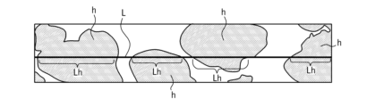
本実施形態の多孔性多層中空糸膜は、三次元網目構造を有することが好ましい。前記三次元網目構造とは、模式的には図1で表すような構造のことである。
例えば、熱可塑性樹脂aが接合して網目を形成し、空隙部bが形成されている。三次元網目構造では、いわゆる球晶構造の樹脂の塊状物がほとんど見られない。三次元網目構造の空隙部bは、熱可塑性樹脂aに囲まれており、空隙部bの各部分は互いに連通していることが好ましい。用いられた熱可塑性樹脂のほとんどが、多孔質膜(好ましくは中空糸膜)の強度に寄与しうる三次元網目構造を形成しているので、高い強度の支持層を形成することが可能になる。また、耐薬品性も向上する。耐薬品性が向上する理由は明確ではないが、強度に寄与しうる網目を形成する熱可塑性樹脂の量が多いため、網目の一部が薬品に侵されても、層全体としての強度には大きな影響が及ばないためではないかと考えられる。
The porous multilayer hollow fiber membrane of this embodiment preferably has a three-dimensional network structure. The three-dimensional network structure is a structure schematically shown in FIG.
For example, thermoplastic resins a are bonded to form a network, and voids b are formed. In the three-dimensional network structure, resin lumps with a so-called spherulite structure are hardly seen. It is preferable that the cavity b of the three-dimensional network structure is surrounded by the thermoplastic resin a, and each part of the cavity b is in communication with each other. Most of the thermoplastic resins used form a three-dimensional network structure that can contribute to the strength of the porous membrane (preferably a hollow fiber membrane), making it possible to form a high-strength support layer. . Moreover, chemical resistance is also improved. The reason for the improvement in chemical resistance is not clear, but because there is a large amount of thermoplastic resin that forms a network that can contribute to strength, even if part of the network is attacked by chemicals, the strength of the entire layer is not affected. This is probably because it does not have a large impact.
本実施形態の多孔性多層中空糸膜は、二層以上の多層構造であり、多層構造のうち、被濾過液側表面を有する層を層(A)とし、濾過液側表面を有する層を層(B)とする。
例えば、多孔性多層中空糸膜の層(A)を、いわゆる阻止層とし、小さい表面孔径により被処理液(原水)中に含まれる異物の膜透過を阻止する機能を発揮させ、多孔性多層中空糸膜の層(B)をいわゆる支持層とし、この支持層は高い機械的強度を担保すると共に、透水性をできるだけ低下させない機能を有するというような機能分担にする。前記層(A)と前記層(B)の機能の分担は、上述したものに限定されるものではない。
The porous multilayer hollow fiber membrane of the present embodiment has a multilayer structure of two or more layers, in which the layer having the surface on the filtrate side is referred to as layer (A), and the layer having the surface on the filtrate side is the layer (A). (B).
For example, the layer (A) of a porous multilayer hollow fiber membrane is made into a so-called blocking layer, and the small surface pore size functions to prevent foreign substances contained in the liquid to be treated (raw water) from permeating through the membrane. The thread membrane layer (B) is a so-called support layer, and this support layer has the functions of ensuring high mechanical strength and minimizing water permeability. The division of functions between the layer (A) and the layer (B) is not limited to that described above.
以下は、本実施形態の多孔性多層中空糸膜を、層(A)が阻止層であり、層(B)が支持層である二層構造の場合について説明する。
前記層(A)の厚みは、多孔性多層中空糸膜の全体の厚さに対して、1/100以上40/100未満とすることが好ましい。このように層(A)の厚みを比較的厚くすることで、原水に砂や凝集物等の不溶物が含まれていても使用可能となる。多少磨耗しても、表面孔径が変化しないからである。この厚みの範囲内であれば、望ましい阻止性能と高い透水性能のバランスがとれる。より好ましくは、多孔性多層中空糸膜の全体の厚さに対して、2/100以上30/100以下である。前記層(A)の厚さは、具体的には、1μm以上100μm以下とすることが好ましく、2μm以上80μm以下とすることがより好ましい。
In the following, the case where the porous multilayer hollow fiber membrane of the present embodiment has a two-layer structure in which the layer (A) is a blocking layer and the layer (B) is a support layer will be described.
The thickness of the layer (A) is preferably 1/100 or more and less than 40/100 of the total thickness of the porous multilayer hollow fiber membrane. By making the layer (A) relatively thick in this way, it can be used even if the raw water contains insoluble matter such as sand and aggregates. This is because the surface pore diameter does not change even if it wears out to some extent. Within this thickness range, a balance between desirable blocking performance and high water permeability can be achieved. More preferably, it is 2/100 or more and 30/100 or less of the total thickness of the porous multilayer hollow fiber membrane. Specifically, the thickness of the layer (A) is preferably 1 μm or more and 100 μm or less, more preferably 2 μm or more and 80 μm or less.
そして、本実施形態の多孔性多層中空糸膜の製造方法は、吐出口を有する中空糸成型用ノズルから、二種以上の異なる溶融混練物を押し出すことで、多層構造の膜を形成する工程を具える。
より具体的には、熱可塑性樹脂、有機液体、無機微粉等を含んだ、二種以上の溶融混練物を、円環状吐出口を有する紡糸口金から吐出して、中空糸状溶融混練物を成形する工程であり、その後、吐出した前記中空糸状溶融混練物を凝固させた後、有機液体及び無機微粉を抽出除去して多孔性多層中空糸膜を作製する工程をさらに具えることが好ましい。
The method for producing a porous multilayer hollow fiber membrane of the present embodiment includes a step of forming a membrane with a multilayer structure by extruding two or more different melt-kneaded materials from a hollow fiber molding nozzle having a discharge port. equip
More specifically, two or more types of melt-kneaded products containing a thermoplastic resin, an organic liquid, an inorganic fine powder, etc. are discharged from a spinneret having an annular discharge port to form a hollow fiber-shaped melt-kneaded product. It is preferable that the method further comprises a step of solidifying the discharged hollow fiber-shaped melt-kneaded material and then extracting and removing the organic liquid and inorganic fine powder to produce a porous multilayer hollow fiber membrane.
本実施形態の多孔性多層中空糸膜の製造方法において用いられる熱可塑性樹脂は、常温では弾性を有し塑性を示さないが、適当な加熱により塑性を現し、成形が可能になる樹脂である。また、熱可塑性樹脂は、冷却して温度が下がると再びもとの弾性体に戻り、その間に分子構造など化学変化を生じない樹脂である(たとえば「化学大辞典編集委員会編集、化学大辞典6縮刷版、共立出版、第860頁及び867頁、1963年」参照)。
The thermoplastic resin used in the method for producing a porous multilayer hollow fiber membrane of this embodiment is a resin that has elasticity and does not exhibit plasticity at room temperature, but exhibits plasticity and becomes moldable by appropriate heating. In addition, thermoplastic resins are resins that return to their original elasticity when cooled and the temperature drops, and do not undergo any chemical changes such as molecular structure during that time (for example, ``Chemistry Encyclopedia Editorial Committee,
熱可塑性樹脂の例としては、12695の化学商品(化学工業日報社、1995年)の熱可塑性プラスチックの項(829~882頁)記載の樹脂や、化学便覧応用編改訂3版(日本化学会編、丸善、1980年)の809-810頁記載の樹脂等を挙げることができる。
前記熱可塑性樹脂の具体例名を挙げると、ポリエチレン、ポリプロピレンのようなポリオレフィン、ポリフッ化ビニリデン等のフッ素樹脂、エチレンービニルアルコール共重合体、ポリアミド、ポリエーテルイミド、ポリスチレン、ポリサルホン、ポリビニルアルコール、ポリフェニレンエーテル、ポリフェニレンサルファイド、酢酸セルロース、ポリアクリロニトリル等である。中でも、結晶性を有するポリオレフィン、ポリフッ化ビニリデン等のフッ素樹脂、エチレンービニルアルコール共重合体、ポリビニルアルコール等の結晶性熱可塑性樹脂は、強度発現の面から好適に用いることができる。さらに好適には、疎水性ゆえ耐水性が高く、通常の水系液体の濾過において耐久性が期待できる、ポリオレフィン、ポリフッ化ビニリデン等のフッ素系樹脂等を用いることができる。
Examples of thermoplastic resins include the resins listed in the thermoplastics section (pages 829-882) of Chemical Products No. 12695 (Kagaku Kogyo Nipposha, 1995), and those listed in the Chemical Handbook, Applied Edition, Revised 3rd Edition (edited by the Chemical Society of Japan). , Maruzen, 1980), pages 809-810.
Specific examples of the thermoplastic resin include polyolefins such as polyethylene and polypropylene, fluororesins such as polyvinylidene fluoride, ethylene-vinyl alcohol copolymers, polyamides, polyetherimides, polystyrene, polysulfone, polyvinyl alcohol, and polyphenylene. These include ether, polyphenylene sulfide, cellulose acetate, and polyacrylonitrile. Among these, polyolefins having crystallinity, fluororesins such as polyvinylidene fluoride, and crystalline thermoplastic resins such as ethylene-vinyl alcohol copolymers and polyvinyl alcohol can be suitably used from the viewpoint of strength development. More preferably, fluororesins such as polyolefins and polyvinylidene fluoride can be used, which have high water resistance due to their hydrophobicity and can be expected to have durability in the filtration of ordinary aqueous liquids.
より具体的には、前記フッ素系樹脂は、フッ化ビニリデン樹脂(PVDF)、クロロトリフルオロエチレン樹脂、テトラフルオロエチレン樹脂、エチレン-テトラフルオロエチレン共重合体(ETFE)、エチレン-モノクロロトリフルオロエチレン共重合体(ECTFE)、ヘキサフルオロプロピレン樹脂、及び、これら樹脂の混合物を1種単独で又は2種以上組み合わせて主成分として含むことが好ましく、これらを1種単独で又は2種以上組み合わせた樹脂のみからなることがより好ましい。特に好適には、前記フッ素系樹脂は、耐薬品性等の化学的耐久性に優れるポリフッ化ビニリデンを用いることができる。
前記ポリフッ化ビニリデンとしては、フッ化ビニリデンホモポリマーや、フッ化ビニリデン比率50モル%以上のフッ化ビニリデン共重合体が挙げられる。フッ化ビニリデン共重合体としては、フッ化ビニリデンと、四フッ化エチレン、六フッ化プロピレン、三フッ化塩化エチレン及びエチレンからなる群より選ばれる1種以上のモノマーとの共重合体を挙げることができる。ポリフッ化ビニリデンとしては、フッ化ビニリデンホモポリマーが特に好ましい。
More specifically, the fluororesin includes vinylidene fluoride resin (PVDF), chlorotrifluoroethylene resin, tetrafluoroethylene resin, ethylene-tetrafluoroethylene copolymer (ETFE), and ethylene-monochlorotrifluoroethylene copolymer. It is preferable to contain a polymer (ECTFE), hexafluoropropylene resin, and a mixture of these resins singly or in combination of two or more types as the main component, and only resins containing these alone or in combination of two or more types. More preferably, it consists of: Particularly preferably, polyvinylidene fluoride, which has excellent chemical durability such as chemical resistance, can be used as the fluororesin.
Examples of the polyvinylidene fluoride include vinylidene fluoride homopolymers and vinylidene fluoride copolymers having a vinylidene fluoride ratio of 50 mol% or more. Examples of vinylidene fluoride copolymers include copolymers of vinylidene fluoride and one or more monomers selected from the group consisting of tetrafluoroethylene, hexafluoropropylene, trifluorochloroethylene, and ethylene. I can do it. As polyvinylidene fluoride, vinylidene fluoride homopolymer is particularly preferred.
さらに、本実施形態の多孔性多層中空糸膜の製造方法において用いられる溶融混練物のうち、少なくとも一種の溶融混練物は、融点が170℃以下である熱可塑性樹脂を含有する。前記熱可塑性樹脂の融点が低い場合、強度が低くなる可能性はあるものの、熱をかけて加工する際に融けやすく、加工性に優れるためである。また、前記熱可塑性樹脂として、前記ポリフッ化ビニリデンを用いた場合、薬品による劣化は柔軟性を発現している非晶質部分から生じているものと推定されることから、一般的に融点が低い方が結晶化度が低くなり、170℃以下とすることが望ましい。 Further, among the melt-kneaded products used in the method for producing a porous multilayer hollow fiber membrane of the present embodiment, at least one kind of melt-kneaded product contains a thermoplastic resin having a melting point of 170° C. or lower. This is because when the melting point of the thermoplastic resin is low, although the strength may be low, it is easy to melt when processed by applying heat and has excellent processability. In addition, when polyvinylidene fluoride is used as the thermoplastic resin, it is assumed that deterioration due to chemicals occurs from the amorphous part that exhibits flexibility, so it generally has a low melting point. The lower the crystallinity, the lower the temperature is preferably 170°C.
なお、本実施形態の多孔性多層中空糸膜の製造方法では、少なくとも一種の溶融混練物が、融点が170℃未満の熱可塑性樹脂を含有しているが、全ての溶融混練物が、融点が170℃未満の熱可塑性樹脂を含有することもできる。この場合、加工性をより改善できる。 In addition, in the method for producing a porous multilayer hollow fiber membrane of the present embodiment, at least one kind of melt-kneaded product contains a thermoplastic resin with a melting point of less than 170°C, but all the melt-kneaded products contain a thermoplastic resin with a melting point of less than 170°C. It may also contain a thermoplastic resin having a temperature of less than 170°C. In this case, workability can be further improved.
また、前記溶融混練物における熱可塑性樹脂の濃度(含有量)は、いずれも30~48質量%であることが好ましく、32~45質量%であることがより好ましい。前記熱可塑性樹脂の含有量が30質量%以上であれば、本実施形態の多孔性多層中空糸膜の機械的強度を担保しやすく、前記熱可塑性樹脂の含有量が48質量%以下であれば、本実施形態の多孔性多層中空糸膜の透水性能の低下が生じない。 Further, the concentration (content) of the thermoplastic resin in the melt-kneaded product is preferably 30 to 48% by mass, more preferably 32 to 45% by mass. If the content of the thermoplastic resin is 30% by mass or more, it is easy to ensure the mechanical strength of the porous multilayer hollow fiber membrane of this embodiment, and if the content of the thermoplastic resin is 48% by mass or less, , the water permeability of the porous multilayer hollow fiber membrane of this embodiment does not deteriorate.
さらに、本実施形態の多孔性多層中空糸膜が二層構造の膜である場合、前記層(B)の溶融混練物における熱可塑性樹脂の濃度(含有量)は、34~48質量%であることが好ましく、35~45質量%であることがより好ましい。一方、前記層(A)の溶融混練物における前記熱可塑性樹脂の濃度(含有量)は、10~35質量%であることが好ましく、12~35質量%未満であることがより好ましい。前記熱可塑性樹脂の含有量が10質量%以上であれば、本実施形態の多孔性多層中空糸膜において表面の孔径と機械的強度を両立することができ、前記熱可塑性樹脂の含有量が135質量%以下であれば、本実施形態の多孔性多層中空糸膜の透水性能の低下が生じない。 Furthermore, when the porous multilayer hollow fiber membrane of the present embodiment is a membrane with a two-layer structure, the concentration (content) of the thermoplastic resin in the melt-kneaded material of the layer (B) is 34 to 48% by mass. It is preferably 35 to 45% by mass, and more preferably 35 to 45% by mass. On the other hand, the concentration (content) of the thermoplastic resin in the melt-kneaded material of the layer (A) is preferably 10 to 35% by mass, more preferably less than 12 to 35% by mass. If the content of the thermoplastic resin is 10% by mass or more, the porous multilayer hollow fiber membrane of this embodiment can achieve both surface pore diameter and mechanical strength, and the content of the thermoplastic resin is 135% by mass or more. If it is less than % by mass, the water permeability of the porous multilayer hollow fiber membrane of this embodiment will not deteriorate.
前記溶融混練物中に含まれる有機液体は、本実施形態で用いる熱可塑性樹脂に対し、潜在的溶剤となるものを用いる。ここで、前記潜在的溶剤とは、室温(25℃)では前記熱可塑性樹脂がほとんど溶解しないが、室温よりも高い温度では該熱可塑性樹脂が溶解できる溶剤のことをいう。前記熱可塑性樹脂との溶融混練温度にて液状であればよく、必ずしも常温で液体である必要はない。 The organic liquid contained in the melt-kneaded material is one that serves as a latent solvent for the thermoplastic resin used in this embodiment. Here, the latent solvent refers to a solvent that hardly dissolves the thermoplastic resin at room temperature (25° C.), but can dissolve the thermoplastic resin at a temperature higher than room temperature. It only needs to be liquid at the melt-kneading temperature with the thermoplastic resin, and does not necessarily need to be liquid at room temperature.
前記熱可塑性樹脂がポリエチレンの場合、有機液体の例としてフタル酸ジブチル、フタル酸ジヘプチル、フタル酸ジオクチル、フタル酸ジ(2-エチルヘキシル)、フタル酸ジイソデシル、フタル酸ジトリデシル等のフタル酸エステル類;セバシン酸ジブチル等のセバシン酸エステル類;アジピン酸ジオクチル等のアジピン酸エステル類;トリメリット酸トリオクチル等のトリメリット酸エステル類;リン酸トリブチル、リン酸トリオクチル等のリン酸エステル類;プロピレングリコールジカプレート、プロピレングリコールジオレエート等のグリセリンエステル類;流動パラフィン等のパラフィン類;及びこれらの混合物等を挙げることができる。 When the thermoplastic resin is polyethylene, examples of the organic liquid include phthalate esters such as dibutyl phthalate, diheptyl phthalate, dioctyl phthalate, di(2-ethylhexyl) phthalate, diisodecyl phthalate, and ditridecyl phthalate; sebacin; Sebacate esters such as dibutyl acid; adipate esters such as dioctyl adipate; trimellitic acid esters such as trioctyl trimellitate; phosphoric acid esters such as tributyl phosphate and trioctyl phosphate; propylene glycol dicaprate; Examples include glycerin esters such as propylene glycol dioleate; paraffins such as liquid paraffin; and mixtures thereof.
前記熱可塑性樹脂がポリフッ化ビニリデンの場合、有機液体の例として、フタル酸ジメチル、フタル酸ジエチル、フタル酸ジブチル、フタル酸ジシクロヘキシル、フタル酸ジヘプチル、フタル酸ジオクチル、フタル酸ジ(2-エチルヘキシル)等のフタル酸エステル類;セバシン酸ジブチル等のセバシン酸エステル類;アジピン酸ジオクチル等のアジピン酸エステル類;メチルベンゾエイト、エチルベンゾエイト等の安息香酸エステル類;リン酸トリフェニル、リン酸トリブチル、リン酸トリクレジル等のリン酸エステル類;γ-ブチロラクトン、エチレンカーボネイト、プロピレンカーボネイト、シクロヘキサノン、アセトフェノン、イソホロン等のケトン類;及びこれらの混合物等を挙げることができる。 When the thermoplastic resin is polyvinylidene fluoride, examples of the organic liquid include dimethyl phthalate, diethyl phthalate, dibutyl phthalate, dicyclohexyl phthalate, diheptyl phthalate, dioctyl phthalate, di(2-ethylhexyl) phthalate, etc. phthalate esters; sebacate esters such as dibutyl sebacate; adipate esters such as dioctyl adipate; benzoate esters such as methyl benzoate and ethyl benzoate; triphenyl phosphate, tributyl phosphate, phosphorus Examples include phosphoric acid esters such as tricresyl acid; ketones such as γ-butyrolactone, ethylene carbonate, propylene carbonate, cyclohexanone, acetophenone, and isophorone; and mixtures thereof.
前記溶融混練物中に含まれる無機微粉としては、シリカ、アルミナ、酸化チタン、酸化ジルコニア、炭酸カルシウム等が挙げられるが、特に平均一次粒子径が3nm以上500nm以下の微粉シリカが好ましい。より好ましくは5nm以上100nm以下である。凝集しにくく分散性の良い疎水性シリカ微粉がより好ましく、さらに好ましくはMW(メタノールウェッタビリティ)値が30容量%以上である疎水性シリカである。ここでいうMW値とは、粉体が完全に濡れるメタノールの容量%の値である。具体的には、純水中にシリカを入れ、攪拌した状態で液面下にメタノールを添加していった時に、シリカの50質量%が沈降した時の水溶液中におけるメタノールの容量%を求めて決定される。上述の「無機微粉の平均一次粒子径」は電子顕微鏡写真の解析から求めた値を意味する。すなわち、まず無機微粉の一群をASTM D3849の方法によって前処理を行う。その後、透過型電子顕微鏡写真に写された3000~5000個の粒子直径を測定し、これらの値を算術平均することで無機微粉の平均一次粒子径を算出する。 Examples of the inorganic fine powder contained in the melt-kneaded material include silica, alumina, titanium oxide, zirconia oxide, calcium carbonate, etc., and particularly preferred is fine silica powder having an average primary particle diameter of 3 nm or more and 500 nm or less. More preferably, the thickness is 5 nm or more and 100 nm or less. Hydrophobic silica fine powder that is difficult to aggregate and has good dispersibility is more preferred, and hydrophobic silica having a MW (methanol wettability) value of 30% by volume or more is even more preferred. The MW value here refers to the volume % of methanol that completely wets the powder. Specifically, when silica is placed in pure water and methanol is added below the liquid surface while stirring, the volume % of methanol in the aqueous solution is determined when 50% by mass of the silica precipitates. It is determined. The above-mentioned "average primary particle diameter of inorganic fine powder" means a value determined from analysis of electron micrographs. That is, first, a group of inorganic fine powders is pretreated by the method of ASTM D3849. Thereafter, the diameters of 3,000 to 5,000 particles captured in a transmission electron micrograph are measured, and the average primary particle diameter of the inorganic fine powder is calculated by taking the arithmetic average of these values.
前記無機微粉の添加量は、前記溶融混練物中に占める無機微粉の質量比率で、5質量~50質量%であることが好ましく、10質量%以上40質量%以下であることがより好ましい。前記溶融混練物中に占める無機微粉の割合が、5質量%以上であれば、無機微粉混練による効果が十分に発現でき、40質量%以下であれば、安定に紡糸できる。 The amount of the inorganic fine powder added is preferably 5 to 50 mass%, more preferably 10 to 40 mass%, as a mass ratio of the inorganic fine powder to the melt-kneaded product. If the proportion of inorganic fine powder in the melt-kneaded material is 5% by mass or more, the effect of inorganic fine powder kneading can be sufficiently exhibited, and if it is 40% by mass or less, stable spinning can be achieved.
前記ポリフッ化ビニリデン及び有機液状体からなる混合物、又は、ポリフッ化ビニリデン、有機液状体及び無機微粉体からなる混合物は、ヘンシェルミキサーやバンバリーミキサー、プロシェアミキサー等を用いて混合することにより得られる。
前記ポリフッ化ビニリデン、有機液状体及び無機微粉体の3成分を混合する場合の順序としては、3成分を同時に混合するよりも、まず無機微粉体と有機液状体を混合して無機微粉体に有機液状体を十分に吸着させ、次いでポリフッ化ビニリデンを配合して混合することが、溶融成形性や得られる多孔膜の空孔率及び機械的強度の向上の点で有利である。
ヘンシェルミキサー等による予備混練を行わずに、直接ポリフッ化ビニリデン及び有機液状体を別々に2軸押出し機等の溶融混練押出し装置に供給しても良い。混練性を上げるために、混合後に一度溶融混練を行ってペレット化し、このペレットを溶融混練押出し装置に供給し、中空糸状に押し出し成形し、冷却固化して中空繊維としてもよい。
The mixture of polyvinylidene fluoride and an organic liquid, or the mixture of polyvinylidene fluoride, an organic liquid, and an inorganic fine powder can be obtained by mixing using a Henschel mixer, a Banbury mixer, a Proshear mixer, or the like.
The order of mixing the three components of polyvinylidene fluoride, organic liquid, and inorganic fine powder is that rather than mixing the three components at the same time, first mix the inorganic fine powder and organic liquid, and then mix the inorganic fine powder with the organic powder. It is advantageous to sufficiently adsorb the liquid material and then blend and mix polyvinylidene fluoride in terms of melt moldability and improvement of the porosity and mechanical strength of the resulting porous membrane.
Polyvinylidene fluoride and the organic liquid may be directly supplied separately to a melt-kneading extrusion device such as a twin-screw extruder without performing preliminary kneading using a Henschel mixer or the like. In order to improve kneading properties, melt-kneading may be performed once after mixing to form pellets, and the pellets may be supplied to a melt-kneading extrusion device, extruded into a hollow fiber shape, and cooled and solidified to form hollow fibers.
前記混合物の溶融混練は、通常の溶融混練手段、例えば押出機を用いて行うことができる。以下に押出機を用いた場合について述べるが、溶融混練の手段は押出機に限るものではない。
本実施形態の製造方法に用いられる製造装置の一例を模式的に示したものを、図2に示す。
The mixture can be melt-kneaded using a conventional melt-kneading means, such as an extruder. The case where an extruder is used will be described below, but the means for melt-kneading is not limited to the extruder.
FIG. 2 schematically shows an example of a manufacturing apparatus used in the manufacturing method of this embodiment.
図2に示す多孔性多層中空糸膜の製造装置は、押出機10と、中空糸成型用ノズル20と、製膜原液を凝固させる溶液が貯留される凝固浴槽30と、多孔性中空糸膜40を搬送して巻き取るための複数のローラ50を備えている。他にも、吸引機(図示せず)や、高温容器(図示せず)を備えることもできる。図2に示すSの空間は、中空糸成型用ノズル20から吐出された成膜原液が、凝固浴槽30中の溶液に到達するまでに通過する空走部である。
The apparatus for manufacturing a porous multilayer hollow fiber membrane shown in FIG. It is equipped with a plurality of
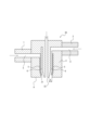
図2に示す多孔性多層中空糸膜の製造装置では、同心円状に配置された1つ以上の円環状吐出口を有する中空糸成型用ノズル20が押出機10の先端に装着され、前記溶融混練物が押出機10によって押し出されて中空糸成型用ノズル20から吐出される。
多孔性多層中空糸膜を製造する場合、図3に示すように、2つ以上の円環状吐出口を有する中空糸成型用ノズル20を押出機10の先端10A、10Bに装着し、それぞれの円環状吐出口にはそれぞれ異なる押出機10より溶融混練物を供給して押出しする方法や、多層中の一層を製造した後、残りの層を塗布する方法がある。
In the porous multilayer hollow fiber membrane production apparatus shown in FIG. The material is extruded by the
When manufacturing a porous multilayer hollow fiber membrane, as shown in FIG. There is a method in which a melt-kneaded material is supplied and extruded from
本実施形態の多孔性多層中空糸膜の製造方法では、2つ以上の円環状吐出口を有する中空糸成型用ノズル20を使用して製造する方法であり、例えば図3に示すように、各々供給される溶融混練物を吐出口で合流させ重ね合わせることで、多層構造を有する中空糸状押出物を得ることができる。このとき、各溶融混練物は、組成の異なる溶融混練物が通る空間25、26を通った後、互いに隣り合う円環状吐出口から押出されることで、互いに隣り合う層の孔径が異なる多層構造の膜を得ることができる。なお、前記溶融混練物の互いに異なる組成とは、溶融混練物の構成物質が異なる場合、又は、構成物質が同じでも構成比率が異なる場合は、組成の異なる溶融混練物となる。さらに、同種の熱可塑性樹脂であっても、分子量や分子量分布が明確に異なる場合は、本発明では構成物質(組成)が異なるとみなす。
なお、上述したように、多層中の一層を製造した後、残りの層を塗布する方法もあるが、工程が増えるため煩雑になる上、界面が溶剤で溶けて緻密化するため高い濾過性能を発現させることは難しい。
In the method for manufacturing a porous multilayer hollow fiber membrane of the present embodiment, a hollow
As mentioned above, there is also a method of manufacturing one of the multiple layers and then applying the remaining layers, but this method increases the number of steps and is complicated, and the interface is dissolved by the solvent and becomes dense, making it difficult to achieve high filtration performance. It is difficult to make it manifest.
そして、本実施形態の多孔性多層中空糸膜の製造方法では、互いに異なる組成の溶融混練物の合流位置が、吐出口より吐出前側にある。前記溶融混練物の合流位置が「吐出口より吐出前側にある」とは、前記中空糸成型用ノズル20の吐出口内で各層を構成する溶融混練物が合流し、その後に吐出される、つまり、前記吐出口内で前記多層多孔性中空糸膜の各層を構成する溶融混練物を合流させた後、合流した溶融混練物を吐出するまでの時間tがt>0秒であることを表す。
前記合流した溶融混練物を吐出するまでの時間tを確保する(t>0とする)ことで、合流後の時間を確保し、膜構造を濾過に好適な構造にすることができる。例えば、融点が170℃より低い熱可塑性樹脂を使用し、二層構造の多孔質膜を製造する場合、吐出されてから固化に至るまでの時間が、融点が低いため融点が高い原料に比べて時間を有する。そのため各層のうち膜の厚み方向の層が徐冷になり一部に球晶構造が発生しやすい状態となる。通常、相溶性がよい有機液体を用いる方が球晶構造を発現しやすい。また各層は異なる孔径の多孔質膜とするため相溶性の異なる有機液体を使用するのが一般的である。そのため、本実施形態では、合流した溶融混練物を吐出するまでの時間tをt>0にすることで、相溶性の異なる各層の有機液体が、合流後に層の界面付近で混合することになり、特に熱可塑性樹脂に対して相溶性が低い層側の界面付近での球晶構造の発現を抑制することができる。球晶構造が発現すると孔と孔の連通性が悪く、濾過性能が低下する傾向にあり三次元網目構造が望ましい。
同様の観点から、前記合流した溶融混練物を吐出するまでの時間tは、t≧0.020秒以上であることが好ましい。
In the method for producing a porous multilayer hollow fiber membrane of the present embodiment, the merging position of the melt-kneaded materials having different compositions is located on the front side of the discharge port. The merging position of the melt-kneaded material "is on the discharge front side from the discharge port" means that the melt-kneaded material constituting each layer joins within the discharge port of the hollow
By ensuring the time t until the merged melt-kneaded material is discharged (t>0), the time after the merge can be secured and the membrane structure can be made suitable for filtration. For example, when manufacturing a two-layered porous membrane using a thermoplastic resin with a melting point lower than 170°C, the time from discharge to solidification is longer than that of a raw material with a higher melting point because the melting point is lower. Have time. Therefore, the layers in the thickness direction of each layer are gradually cooled, and a spherulite structure is likely to occur in some parts. Generally, it is easier to develop a spherulite structure when an organic liquid with good compatibility is used. Furthermore, since each layer is a porous membrane with a different pore size, it is common to use organic liquids with different compatibility. Therefore, in this embodiment, by setting the time t until discharge of the combined molten kneaded material to be t>0, the organic liquids of each layer having different compatibility will mix near the interface of the layers after joining. In particular, it is possible to suppress the development of a spherulite structure near the interface on the side of the layer that has low compatibility with the thermoplastic resin. When a spherulite structure develops, the communication between the pores is poor and the filtration performance tends to decrease, so a three-dimensional network structure is desirable.
From the same viewpoint, it is preferable that the time t until the combined melt-kneaded material is discharged is t≧0.020 seconds or more.
なお、前記熱可塑性樹脂として、上述したポリフッ化ビニリデンを用いる場合、高い開孔率と高い耐圧縮強度を両立させるためには、前記ポリフッ化ビニリデンの溶媒を適当に選定する必要がある。まず開孔率を上げる方法として、ポリフッ化ビニリデンの濃度を下げる方法や、前述のとおり、中空部形成用流体の温度を高くする方法がある。ポリフッ化ビニリデン濃度を下げて製膜する方法を用いる場合、孔径もあわせて大きくなってしまうため、高開孔率且つ小孔径を達成できる溶媒を選定することが必要である。
下記のパラメータPは、ポリフッ化ビニリデンの三次元溶解度パラメータと、溶媒の三次元溶解度パラメータの関係式であり、ポリフッ化ビニリデンと溶媒の溶解性を評価するものである。右辺は、三次元的にHansen溶解度パラメータの溶解範囲を表すもので、PVDFの三次元溶解度パラメータ(σdp、σpp、σhp)から溶媒の三次元溶解度パラメータ(σdm、σpm、σhm)までの距離を定量的に表す。
P=(4×(σdm-σdp)2+(σpm-σpp)2+(σhm-σhp)2)×0.5
[式中、σdm及びσdpは溶媒及びポリフッ化ビニリデンの分散力項をそれぞれ示し、σpm及びσppは溶媒及びポリフッ化ビニリデンの双極子結合力項をそれぞれ示し、σhm及びσhpは溶媒及びポリフッ化ビニリデンの水素結合項をそれぞれ示す。]
なお、上記の考え方はポリフッ化ビニリデンに限るものではなく、他の熱可塑性樹脂にも適用することが可能である。
In addition, when the above-mentioned polyvinylidene fluoride is used as the thermoplastic resin, in order to achieve both high porosity and high compressive strength, it is necessary to appropriately select the solvent for the polyvinylidene fluoride. First, as a method of increasing the porosity, there are a method of lowering the concentration of polyvinylidene fluoride and a method of increasing the temperature of the hollow part forming fluid as described above. When using a method of forming a film by lowering the polyvinylidene fluoride concentration, the pore size also increases, so it is necessary to select a solvent that can achieve a high porosity and a small pore size.
The following parameter P is a relational expression between the three-dimensional solubility parameter of polyvinylidene fluoride and the three-dimensional solubility parameter of the solvent, and is used to evaluate the solubility of polyvinylidene fluoride and the solvent. The right side represents the solubility range of the Hansen solubility parameters three-dimensionally, and the distance from the three-dimensional solubility parameters of PVDF (σdp, σpp, σhp) to the three-dimensional solubility parameters of the solvent (σdm, σpm, σhm) is quantified. expressed in terms of
P=(4×(σdm-σdp)2+(σpm-σpp)2+(σhm-σhp)2)×0.5
[In the formula, σdm and σdp represent the dispersion force terms of the solvent and polyvinylidene fluoride, respectively, σpm and σpp represent the dipole binding force terms of the solvent and polyvinylidene fluoride, respectively, and σhm and σhp represent the dispersion force terms of the solvent and polyvinylidene fluoride, respectively. Each hydrogen bond term is shown. ]
Note that the above concept is not limited to polyvinylidene fluoride, and can be applied to other thermoplastic resins.
二層構造の多孔質膜である場合、前記多孔性多層中空糸膜における濾過液側の表面である表面FBを含む層(B)を形成する溶融混練物の調製に使用する溶媒とポリフッ化ビニリデンの間のパラメータPbが、好ましくは7.95より大きく、より好ましくは7.98から10であり、更に好ましくは7.8から9.0である。この値が7.95より大きいと透水性の低下を抑制できる。 In the case of a porous membrane with a two-layer structure, the solvent and polyvinylidene fluoride used to prepare the melt-kneaded material forming the layer (B) containing the surface FB, which is the surface on the filtrate side of the porous multilayer hollow fiber membrane. The parameter Pb between is preferably greater than 7.95, more preferably from 7.98 to 10, and even more preferably from 7.8 to 9.0. When this value is larger than 7.95, a decrease in water permeability can be suppressed.
また、前記多孔性多層中空糸膜における被濾過液側の表面である表面FAを含む層(A)を形成する溶融混練物Aの調製には、使用する溶媒とポリフッ化ビニリデンの間のパラメータPaが、好ましくは7.95以下であり、より好ましくは0から7.95であり、更に好ましくは3.0から7.89である。この値が7.95以下であると、高開孔率かつ小孔径を達成することができる。 In addition, in preparing the melt-kneaded material A forming the layer (A) containing the surface FA, which is the surface on the side of the liquid to be filtered in the porous multilayer hollow fiber membrane, the parameter Pa between the solvent used and polyvinylidene fluoride is is preferably 7.95 or less, more preferably 0 to 7.95, still more preferably 3.0 to 7.89. When this value is 7.95 or less, a high porosity and a small pore diameter can be achieved.
ここで、前記層(A)と前記層(B)の溶解度パラメータの差Pb-PaはPb-Pa>0.05であることが好ましい。前記層(A)はポリフッ化ビニリデンと溶媒の相溶性がよいため球晶構造が発生しやすいが、Pb-Pa>0.05であると、前記層(B)の溶媒と界面で層(A)と層(B)が合流し混合した後、相溶性が適度に下がるため球晶構造の形成を抑制できる。 Here, the difference in solubility parameters Pb-Pa between the layer (A) and the layer (B) is preferably Pb-Pa>0.05. Since the layer (A) has good compatibility between polyvinylidene fluoride and the solvent, a spherulite structure is likely to occur, but if Pb-Pa>0.05, the layer (A) will form at the interface with the solvent of the layer (B). ) and layer (B) are combined and mixed, the compatibility decreases to an appropriate degree, so the formation of a spherulite structure can be suppressed.
また、本実施形態の多孔性多層中空糸膜の製造方法では、前記層(A)と層(B)を形成させる溶融混練物を押し出す際の溶融混練機の温度差は5℃以上が好ましい。5℃以上にすると機械的強度を高くすることができる。さらに好ましくは層(B)の溶融混練機の温度を層(A)の溶融混練機の温度に対して5℃以上高くすることが好ましい。理由は定かではないが、これはポリフッ化ビニリデンと溶媒の相溶性からより相溶性が低い層(B)の温度を高くすることでより、より溶解状態を層(A)と層(B)で近づけることができ2つの溶融混練物が合流した際によりポリフッ化ビニリデン同士の絡み合いが増加するためと推定している。 Further, in the method for producing a porous multilayer hollow fiber membrane of the present embodiment, the temperature difference between the melt kneaders when extruding the melt kneaded material forming the layer (A) and the layer (B) is preferably 5° C. or more. When the temperature is 5°C or higher, mechanical strength can be increased. More preferably, the temperature of the melt-kneader for layer (B) is higher than the temperature of the melt-kneader for layer (A) by 5° C. or more. The reason for this is not clear, but due to the compatibility of polyvinylidene fluoride and the solvent, increasing the temperature of layer (B), which has lower compatibility, makes it possible to achieve a more dissolved state between layer (A) and layer (B). It is presumed that this is because polyvinylidene fluoride becomes more entangled with each other when the two melted and kneaded materials join together.
また、前記中空糸成型用ノズル20の円環状吐出口から溶融混練物を押出す際、紡口吐出パラメータR(1/秒)が10以上1000以下の値になるように吐出すると、高い生産性と紡糸安定性さらに高強度の膜が得られるため、好ましい。ここで、紡口吐出パラメータRとは、吐出線速V(m/秒)を、吐出口のスリット幅d(m)で除した値である。吐出線速V(m/秒)は、溶融混練物の時間当たりの吐出容量(m3/秒)を吐出口の断面積(m2)で除した値である。Rが10以上であれば、中空状押出し物の糸径が脈動する等の問題が無く、生産性良く安定に紡糸できる。またRが1000以下であれば、得られる多孔性中空糸膜の重要な強度の一つである破断伸度が十分に高く維持できる。破断伸度とは、膜長手方向に引っ張った時の元の長さに対する伸び率(%)のことである。
Furthermore, when extruding the melt-kneaded material from the annular discharge port of the hollow
本実施形態の多孔性多層中空糸膜の製造方法では、各溶融混練物が合流した後に積層された溶融混練物の吐出線速Vを吐出口のスリット幅dで除した値を紡口吐出パラメータ(R)が、50以上1000以下であることが好ましい。 In the method for producing a porous multilayer hollow fiber membrane of the present embodiment, the value obtained by dividing the discharge linear velocity V of the laminated melt-kneaded material by the slit width d of the discharge port after each melt-kneaded material joins is determined as the spindle discharge parameter. (R) is preferably 50 or more and 1000 or less.
前記中空糸成型用ノズル20の吐出口から吐出された中空糸状溶融混練物は、空気や水等の冷媒を通過して凝固させるが、目的とする多孔性中空糸膜によって、空気層からなる上述した空走部Sを通過させたのちに、水等が入った凝固浴槽30を通過させる。すなわち空走部Sとは、中空糸成型用ノズル20の吐出口から凝固浴槽30の水面までの部分である。吐出口から必要に応じて空走部Sには筒等の容器を用いても良い。凝固浴槽30を通過後、必要に応じてかせ等に巻き取られる。
The hollow fiber-shaped molten kneaded material discharged from the discharge port of the hollow
また、前記可塑性樹脂は、ペレット又は粒状でもよい。ペレット又は粒状の熱可塑性樹脂を粉砕する手段としては、ペレットを粗粉砕しその後微粉砕する多段粉砕方式や、微細化まで一段で行う方式等があるが、その方式は限定されるものではない。微粉砕機によっても、微粉が所定の粒径に達しない場合は、更なる微粉砕が可能な超微粉砕機により粉砕する。具体的な粉砕手段としては、ハンマーミル、ターボミル、ジェットミル、ピンミル、遠心ミル、ロートプレックス、パルベルイザー、湿式粉砕、チョッパーミル、ウルトラローター等を用いる粉砕手段が挙げられ、常温あるいは凍結粉砕方式を用いることができる。例えば、ガラス転移点が約-35℃と低いフッ化ビニリデン系樹脂は凍結粉砕方式をとることが好適である。 Furthermore, the plastic resin may be in the form of pellets or particles. Means for pulverizing pellets or granular thermoplastic resins include a multistage pulverization method in which the pellets are roughly pulverized and then finely pulverized, and a method in which pulverization is performed in one step, but the method is not limited. If the fine powder does not reach a predetermined particle size even with the pulverizer, it is pulverized with an ultrafine pulverizer capable of further pulverization. Specific pulverization means include those using a hammer mill, turbo mill, jet mill, pin mill, centrifugal mill, rotoplex, pulverizer, wet pulverization, chopper mill, ultra rotor, etc., and room temperature or frozen pulverization methods are used. be able to. For example, for vinylidene fluoride resins whose glass transition point is as low as about -35° C., it is preferable to use a freeze-pulverization method.
所定の粒径範囲の微粉を得るために適切な分級機を使用して分級が行われる。分級後の微粉から所定粒径範囲のものを得る場合は、さらに別の分級機で分級した後、所定粒径以下の微細粉を除去し、残った微粉(中粉)を製品とする場合もある。分級し、目的とする粒子径範囲より大きい範囲の粒子は再度、粉砕して所定粒子径範囲のものを得ることもできる。分級に用いられる装置として、振動篩機や慣性気流式分級機、回転羽根式分級機などがあり特に限定されるものではない。 Classification is carried out using a suitable classifier to obtain a fine powder of a predetermined particle size range. If you want to obtain particles within a predetermined particle size from the fine powder after classification, you may classify it using another classifier, remove the fine powder below the predetermined particle size, and use the remaining fine powder (medium powder) as a product. be. After classification, particles larger than the target particle size range can be crushed again to obtain particles within a predetermined particle size range. Devices used for classification include vibrating sieves, inertial air classifiers, rotary vane classifiers, and the like, but are not particularly limited.
また2種類の高分子成分を混合させる場合は、各高分子成分を粉砕してから、混合機を用いて混合して用いてもよい。分級は粉砕後に実施もしくは混合後に分級してもよく特に限定されるものではない。
粉砕後の粒子径分布の測定は、レーザー回折、散乱式粒度分布測定装置を使用し、粒子径分布を得ることができる。
In addition, when two types of polymer components are mixed, each polymer component may be ground and then mixed using a mixer. Classification may be performed after pulverization or after mixing, and is not particularly limited.
The particle size distribution after pulverization can be measured using a laser diffraction or scattering particle size distribution measuring device.
また、前記可塑性樹脂の粒子径分布から得られる体積基準のメディアン径(D50粒子径)は50μm以上500μm以下の範囲にあることが好ましい。50μm以上であれば、例えば押出機等で溶融混練する際に投入時にスクリューへの噛み込み不良などが発生せず安定して投入することができる。500μm以下であれば、溶解不良などが発生せず安定して多孔質膜を製造することができる。 Further, the volume-based median diameter (D50 particle diameter) obtained from the particle diameter distribution of the plastic resin is preferably in the range of 50 μm or more and 500 μm or less. If the diameter is 50 μm or more, the material can be stably charged without causing problems such as jamming into the screw when being melted and kneaded using an extruder or the like. If it is 500 μm or less, a porous membrane can be stably manufactured without causing poor dissolution.
同様に、前記可塑性樹脂の粒子径分布からD10粒子径、D90粒子径が得られる。得られたD10、D50、D90粒子径から粒子径分散度V=(D90-D10)/D50と定義した場合に、Vが0.8より大きいことが好ましい。より好ましくは1.3以上である。 Similarly, the D10 particle size and D90 particle size are obtained from the particle size distribution of the plastic resin. When defining the particle size dispersity V=(D90-D10)/D50 from the obtained D10, D50, and D90 particle sizes, it is preferable that V is larger than 0.8. More preferably it is 1.3 or more.
凝固後の中空糸状物中には、ポリマー濃厚部分相と有機液体濃厚部分相とが微細に分かれて存在する。なお、例えば、無機微粉を添加した場合に、その無機微粉が微粉シリカである場合、微粉シリカは有機液体濃厚部分相に偏在する。この中空糸状物から有機液体と無機微粉を抽出除去することで、有機液体濃厚相部分が空孔となる。よって多孔性中空糸膜を得ることができる。
粒子径分散度が大きい方が熱可塑性樹脂の微粉が、凝集した無機微粉や無機微粉と無機微粉の間に入り込むことで、多孔質膜のポリマー部と空孔部を形成する熱可塑性樹脂と無機微粉の混合性が向上し、より均一な多孔質膜の構造を得ることができ膜性能のばらつきを低減することができる。多孔質膜の均一性は膜性能のばらつきにより評価することができる。
In the hollow fiber-like material after solidification, a polymer-rich partial phase and an organic liquid-rich partial phase are finely divided and exist. For example, when an inorganic fine powder is added and the inorganic fine powder is fine silica, the fine silica is unevenly distributed in the organic liquid concentrated partial phase. By extracting and removing the organic liquid and inorganic fine powder from this hollow fiber, the organic liquid concentrated phase portion becomes pores. Therefore, a porous hollow fiber membrane can be obtained.
If the particle size dispersion is larger, the thermoplastic resin fine powder will enter between the aggregated inorganic fine powder or between the inorganic fine powder and the inorganic fine powder, and the thermoplastic resin and inorganic resin will form the polymer part and the pores of the porous membrane. The mixability of fine powder is improved, a more uniform porous membrane structure can be obtained, and variations in membrane performance can be reduced. The uniformity of a porous membrane can be evaluated by the variation in membrane performance.
粉砕後のD50粒子径と無機微粉の一次粒子径の比は3200から35000にあることが好ましい。3200以上であれば、ポリフッ化ビニリデン、有機液状体及び無機微粉体の3成分を混合して押出機に投入した場合に、押出機の温度が安定する時間が早くなる。混合後は、ポリマー壁面にシリカが付着すると想定されるが、3200以上であれば、ポリマー壁面がシリカで覆われず露出される面が大きくなるため熱がポリマーへの熱が伝わりやすくなり温度の安定が早くなると推定される。特に、理由はないが35000以下であれば安定的に混合することができる。 The ratio of the D50 particle size after pulverization to the primary particle size of the inorganic fine powder is preferably 3,200 to 35,000. If it is 3200 or more, when the three components of polyvinylidene fluoride, organic liquid, and inorganic fine powder are mixed and charged into an extruder, the time for the temperature of the extruder to stabilize becomes faster. After mixing, it is assumed that silica will adhere to the polymer wall surface, but if it is 3200 or higher, the polymer wall surface will not be covered with silica and the exposed surface will be large, making it easier for heat to be transmitted to the polymer and causing a decrease in temperature. It is estimated that stability will be faster. Although there is no particular reason, stable mixing can be achieved if it is 35,000 or less.
なお、粉砕後の粒子形状は、円形度が0.5以下であることが好ましい。円形度が小さい方が、嵩密度が高くなりやすくなり押出機への投入が安定化する。円形度は、式(A)で表され、1.0に近い方が円形に近い形状を表す。

また線形度は1.8以上であることが好ましい。線形度が大きい方が、有機液状体及び無機微粉体の3成分を混合した際に嵩密度が安定化する前に粒子同士の間隙が増えるため無機微粉体との混合性が向上する。線形度は、式(B)で表され、円に近いほど1.0に近い値とある。細長いものほど大きな値となる。

前記有機液体の抽出除去及び無機微粉の抽出除去は、同じ溶剤にて抽出除去できる場合であれば同時に行うことができる。通常は別々に抽出除去する。
前記有機液体の抽出除去は、用いた熱可塑性樹脂を溶解あるいは変性させずに有機液体とは混和する、抽出に適した液体を用いる。具体的には浸漬等の手法により接触させることで行うことができる。該液体は、抽出後に中空糸膜から除去しやすいように、揮発性であることが好ましい。該液体の例としては、アルコール類や塩化メチレン等がある。有機液体が水溶性であれば水も抽出用液体として使うことが可能である。
無機微粉の抽出除去は、通常、水系の液体を用いて行う。例えば無機微粉がシリカである場合、まずアルカリ性溶液と接触させてシリカをケイ酸塩に転化させ、次いで水と接触させてケイ酸塩を抽出除去することで行うことができる。
The extraction and removal of the organic liquid and the extraction and removal of the inorganic fine powder can be performed simultaneously if the extraction and removal can be performed using the same solvent. Usually extracted and removed separately.
For the extraction and removal of the organic liquid, a liquid suitable for extraction is used that is miscible with the organic liquid without dissolving or denaturing the thermoplastic resin used. Specifically, this can be carried out by contacting by a method such as immersion. Preferably, the liquid is volatile so that it can be easily removed from the hollow fiber membrane after extraction. Examples of such liquids include alcohols and methylene chloride. Water can also be used as the extraction liquid if the organic liquid is water-soluble.
Extraction and removal of inorganic fine powder is usually performed using an aqueous liquid. For example, when the inorganic fine powder is silica, this can be carried out by first contacting with an alkaline solution to convert the silica into silicate, and then contacting with water to extract and remove the silicate.
有機液体の抽出除去と無機微粉の抽出除去とは、どちらが先でも差し支えはない。有機液体が水と非混和性の場合は、先に有機液体の抽出除去を行い、その後に無機微粉の抽出除去を行う方が好ましい。通常有機液体及び無機微粉は有機液体濃厚部分相に混和共存しているため、無機微粉の抽出除去をスムーズに進めることができ、有利である。 It does not matter which one comes first, the extraction removal of the organic liquid or the extraction removal of the inorganic fine powder. When the organic liquid is immiscible with water, it is preferable to first extract and remove the organic liquid and then extract and remove the inorganic fine powder. Since the organic liquid and the inorganic fine powder usually coexist in a mixed manner in the concentrated organic liquid partial phase, the extraction and removal of the inorganic fine powder can proceed smoothly, which is advantageous.
このように、凝固した多孔性中空糸膜から有機液体や無機微粉を抽出除去することにより、多孔性中空糸膜を得ることができる。
なお、凝固後の中空糸膜に対し、(i)有機液体及び無機微粉の抽出除去前、(ii)有機液体の抽出除去後で無機微粉の抽出除去前、(iii)無機微粉の抽出除去後で有機液体の抽出除去前、(iv)有機液体及び無機微粉の抽出除去後、のいずれかの段階で、多孔性中空糸膜の長手方向への延伸を、延伸倍率3倍以内の範囲で行うことができる。一般に中空糸膜を長手方向に延伸すると透水性能は向上するが、耐圧性能(破裂強度及び耐圧縮強度)が低下するため、延伸後は実用的な強度の膜にならない場合が多い。しかしながら、本実施形態の製造方法で得られる多孔性中空糸膜は機械的強度が高い。よって延伸倍率1.1倍以上3.0倍以内の延伸は実施可能である。延伸により、多孔性中空糸膜の透水性能が向上する。ここで言う延伸倍率とは、延伸後の中空糸長を延伸前の中空糸長で割った値を指す。
例えば、中空糸長10cmの多孔性中空糸膜を、延伸して中空糸長を20cmまで伸ばした場合、下記式より、延伸倍率は2倍である。
20cm÷10cm=2
In this way, a porous hollow fiber membrane can be obtained by extracting and removing the organic liquid and inorganic fine powder from the solidified porous hollow fiber membrane.
In addition, for the hollow fiber membrane after solidification, (i) before extraction and removal of organic liquid and inorganic fine powder, (ii) after extraction and removal of organic liquid and before extraction and removal of inorganic fine powder, (iii) after extraction and removal of inorganic fine powder (iv) before the extraction and removal of the organic liquid; (iv) after the extraction and removal of the organic liquid and inorganic fine powder; stretching the porous hollow fiber membrane in the longitudinal direction at a stretching ratio of 3 times or less; be able to. Generally, when a hollow fiber membrane is stretched in the longitudinal direction, water permeability improves, but pressure resistance (burst strength and compressive strength) decreases, so the membrane often does not have a practical strength after stretching. However, the porous hollow fiber membrane obtained by the manufacturing method of this embodiment has high mechanical strength. Therefore, stretching at a stretching ratio of 1.1 times or more and 3.0 times or less is possible. Stretching improves the water permeability of the porous hollow fiber membrane. The stretching ratio here refers to the value obtained by dividing the hollow fiber length after stretching by the hollow fiber length before stretching.
For example, when a porous hollow fiber membrane with a hollow fiber length of 10 cm is stretched to extend the hollow fiber length to 20 cm, the stretching ratio is 2 times according to the following formula.
20cm÷10cm=2
前記多孔性中空糸膜の延伸は、空間温度0℃以上160℃以下で行うことが望ましい。160℃より高い場合には延伸斑が大きいうえに破断伸度の低下及び透水性能が低くなり好ましくなく、0℃以下では延伸破断の可能性が高く実用的でない。延伸工程中の空間温度を10℃以上140℃以下とすることがより好ましく、さらに好ましくは20℃以上100℃以下である。 It is desirable that the porous hollow fiber membrane be stretched at a space temperature of 0°C or higher and 160°C or lower. If the temperature is higher than 160°C, stretching unevenness will be large, and the elongation at break will be lowered, and the water permeability will be lowered, which is undesirable. If it is lower than 0°C, there is a high possibility of stretching breakage, which is not practical. It is more preferable that the space temperature during the stretching step is 10°C or more and 140°C or less, and even more preferably 20°C or more and 100°C or less.
本実施形態の製造方法では、有機液状体を含んだ多孔性中空糸膜を延伸することが好ましい。有機液状体を含んだ中空糸膜の方が、有機液状体を含んでいない中空糸膜よりも、延伸時の破断が少ない。さらに、有機液状体を含んだ中空糸膜の方が、延伸後の中空糸膜の収縮を大きくさせることができるため、延伸後の収縮率設定の自由度が増す。 In the manufacturing method of this embodiment, it is preferable to stretch a porous hollow fiber membrane containing an organic liquid. Hollow fiber membranes containing an organic liquid have less breakage during stretching than hollow fiber membranes that do not contain an organic liquid. Furthermore, since hollow fiber membranes containing an organic liquid can have greater shrinkage after stretching, the degree of freedom in setting the shrinkage rate after stretching increases.
また、無機微粉体を含んだ多孔性中空糸膜を延伸することが好ましい。無機微粉体を含んだ中空糸膜の方が、中空糸膜に含まれる無機微粉体の存在による中空糸膜の硬さのために、延伸する際において中空糸膜が扁平につぶれにくくなる。また、最終的に得られる中空糸膜の孔径が小さくなりすぎたり、糸径が細くなりすぎたりすることを防止することもできる。
本発明においては、有機液状体及び無機微粉体の両方を含む中空糸膜を延伸することがより望ましい。
Moreover, it is preferable to stretch a porous hollow fiber membrane containing inorganic fine powder. Hollow fiber membranes containing inorganic fine powder are less likely to flatten during stretching due to the hardness of the hollow fiber membrane due to the presence of the inorganic fine powder contained in the hollow fiber membrane. Moreover, it is also possible to prevent the pore diameter of the finally obtained hollow fiber membrane from becoming too small or the fiber diameter from becoming too thin.
In the present invention, it is more desirable to stretch a hollow fiber membrane containing both an organic liquid and an inorganic fine powder.
上述の理由により、抽出終了後に中空糸膜を延伸するよりも、有機液状体又は無機微粉体のいずれか一方を含んだ中空糸膜を延伸する方が好ましく、さらに、有機液状体又は無機微粉体のいずれか一方を含んだ中空糸膜を延伸するよりも、有機液状体及び無機微粉体の両方を含んだ中空糸膜を延伸することがより好ましい。 For the reasons mentioned above, it is preferable to stretch a hollow fiber membrane containing either an organic liquid or an inorganic fine powder than to stretch a hollow fiber membrane after the extraction is completed. It is more preferable to stretch a hollow fiber membrane containing both an organic liquid and an inorganic fine powder than to stretch a hollow fiber membrane containing either one of them.
また、延伸した中空糸膜を抽出する方法は、延伸により中空糸膜の表面及び内部に空隙が増加しているため、抽出溶剤が中空糸膜内部に浸透し易いという利点がある。また、延伸し、次いで収縮させる工程の後に抽出を行う方法は、後述のように、引っ張り弾性率の低い、曲がり易い中空糸膜となるために、抽出を液流中で行う場合には、中空糸膜が液流により揺れ易くなり、攪拌効果が増すために短時間で効率の高い抽出が可能となるという利点を有する。 Furthermore, the method of extracting a stretched hollow fiber membrane has the advantage that the extraction solvent easily permeates inside the hollow fiber membrane, since voids are increased on the surface and inside of the hollow fiber membrane due to stretching. In addition, when extraction is carried out after the stretching and then shrinking process, as will be described later, the result is a hollow fiber membrane that has a low tensile modulus and is easy to bend. This method has the advantage that the thread membrane is easily shaken by the liquid flow and the stirring effect is increased, allowing highly efficient extraction in a short period of time.
本実施形態の製造方法では、中空糸膜を延伸し、次いで収縮させる工程を有しているため、最終的に引っ張り弾性率の低い中空糸膜を得ることができる。ここで、「引っ張り弾性率が低い」とは、糸が小さな力で伸びやすく、力がなくなればまた元に戻ることを意味する。引っ張り弾性率が低いと、中空糸膜が扁平につぶれることなく、曲がりやすく、濾過の際に水流で揺れやすい。水流に従って糸の曲がりが一定せずに揺れることで、膜表面に付着堆積する汚染物質の層が成長せずに剥がれやすく、濾過水量を高く維持できる。更にはフラッシングやエアースクラビングで強制的に糸を揺らす場合に、揺れが大きく洗浄回復効果が高くなる。 Since the manufacturing method of this embodiment includes the steps of stretching and then shrinking the hollow fiber membrane, it is possible to finally obtain a hollow fiber membrane with a low tensile modulus. Here, "low tensile modulus" means that the thread stretches easily with a small force and returns to its original state when the force is removed. When the tensile modulus is low, the hollow fiber membrane does not flatten and is easily bent, and easily shaken by water flow during filtration. The uneven bending of the threads sways as the water flows, allowing the layer of contaminants that adhere to and accumulate on the membrane surface to easily peel off without growing, making it possible to maintain a high amount of filtered water. Furthermore, when the thread is forcibly shaken during flushing or air scrubbing, the shaking is large and the cleaning recovery effect is enhanced.
延伸した後に収縮を行う際の糸長収縮の程度については、延伸による糸長増分に対する糸長収縮率を0.3以上0.9以下の範囲とすることが望ましい。例えば、10cmの糸を延伸して20cmにし、その後14cmにさせた時は、以下の式より、
糸長収縮率={(延伸時最大糸長)-(収縮後糸長)}/[(延伸時最大糸長)-(元糸長)]=(20-14)/(20-10)=0.6
糸長収縮率は0.6となる。糸長収縮率が0.9以上の場合は透水性能が低くなり易く、0.3未満の場合は引っ張り弾性率が高くなり易いため好ましくない。本発明においては、糸長収縮率が0.50以上0.85以下の範囲内であることがより好ましい。
Regarding the degree of yarn length contraction when shrinking is performed after stretching, it is desirable that the yarn length contraction rate with respect to the yarn length increment due to stretching is in the range of 0.3 or more and 0.9 or less. For example, when a 10 cm thread is stretched to 20 cm and then to 14 cm, from the following formula,
Yarn length shrinkage rate = {(Maximum yarn length during stretching) - (Yam length after contraction)} / [(Maximum yarn length during stretching) - (Original yarn length)] = (20-14) / (20-10) = 0.6
The yarn length shrinkage rate is 0.6. If the yarn length contraction rate is 0.9 or more, water permeability tends to be low, and if it is less than 0.3, the tensile modulus tends to be high, which is not preferable. In the present invention, it is more preferable that the yarn length contraction rate is within the range of 0.50 or more and 0.85 or less.
また、中空糸膜を延伸時最大糸長まで延伸し、次いで収縮させる工程を採ることにより、最終的に得られる中空糸膜は使用中に延伸時最大糸長まで伸ばした際にも切れることがなくなる。
ここで、延伸倍率をX、延伸による糸長増分に対する糸長収縮率をYとしたとき、破断伸度の保障の程度を表す率Zは、以下の式で定義できる。
Z=(延伸時最大糸長-収縮後糸長)/収縮後糸長=(XY-Y)/(X+Y-XY)
Zは0.2以上1.5以下が好ましく、より好ましくは、Zは0.3以上1.0以下である。Zが小さすぎると破断伸度の保障が少なくなり、Zが大きすぎると延伸時の破断の可能性が高くなるわりに透水性能が低くなる。
In addition, by employing the process of stretching the hollow fiber membrane to the maximum fiber length during stretching and then shrinking it, the finally obtained hollow fiber membrane will not break even when stretched to the maximum fiber length during use. It disappears.
Here, when the stretching ratio is X and the yarn length shrinkage rate with respect to the yarn length increment due to stretching is Y, the rate Z representing the degree of guarantee of elongation at break can be defined by the following formula.
Z = (maximum yarn length during stretching - yarn length after contraction) / yarn length after contraction = (XY-Y) / (X+Y-XY)
Z is preferably 0.2 or more and 1.5 or less, more preferably 0.3 or more and 1.0 or less. If Z is too small, the elongation at break will be less guaranteed, and if Z is too large, the possibility of breakage during stretching will increase, but the water permeability will be low.
また、本実施形態の製造方法では、延伸し、次いで収縮させる工程を含むため、引っ張り破断伸度は低伸度での破断が極めて少なくなり、引っ張り破断伸度の分布を狭くすることができる。 Moreover, since the manufacturing method of this embodiment includes the step of stretching and then shrinking, the tensile elongation at break is extremely less likely to break at low elongation, and the distribution of the tensile elongation at break can be narrowed.
延伸し、次いで収縮させる工程における空間温度は、収縮の時間や物性の点から、0℃以上160℃以下の範囲が望ましい。0℃より低いと収縮に時間がかかり実用的でなく、160℃を超えると破断伸度の低下及び透水性能が低くなり好ましくない。 The space temperature in the step of stretching and then shrinking is preferably in the range of 0° C. or higher and 160° C. or lower from the viewpoint of shrinking time and physical properties. If it is lower than 0°C, it will take a long time to shrink, which is not practical, and if it exceeds 160°C, the elongation at break and water permeability will be low, which is not preferable.
また、本実施形態の製造方法では、においては、収縮工程中において、中空糸膜を捲縮することが好ましい。これにより捲縮度の高い中空糸膜を、つぶれ或いは傷つけることなく得ることができる。 Further, in the manufacturing method of the present embodiment, it is preferable that the hollow fiber membrane is crimped during the shrinking step. Thereby, a hollow fiber membrane with a high degree of crimp can be obtained without being crushed or damaged.
一般に、多孔性中空糸膜は、曲がりの無い直管状の形態をなしているため、束ねて濾過用モジュールとした場合に、中空糸間の隙間が取れずに空隙度の低い糸束になる可能性が高い。これに対して、捲縮度が高い中空糸膜を用いると、個々の糸の曲がりにより平均的に中空糸膜間隔が広がり空隙度の高い糸束とすることができる。また、捲縮度の低い中空糸膜からなる濾過モジュールは、特に外圧で用いる際に糸束の空隙が少なくなり流動抵抗が増大し、糸束の中央部まで濾過圧力が有効に伝わらなくなる。更には、逆洗やフラッシングで濾過堆積物を中空糸膜から剥ぎ落とす際にも糸束内部の洗浄効果が小さくなる。捲縮度の高い多孔性多層中空糸膜からなる糸束は、空隙度が大きく外圧濾過でも中空糸膜間隙が保たれ、偏流が起こりにくい。 In general, porous hollow fiber membranes have a straight tube-like shape without bending, so when they are bundled together to form a filtration module, the gaps between the hollow fibers cannot be removed, resulting in a fiber bundle with low porosity. Highly sexual. On the other hand, when hollow fiber membranes with a high degree of crimp are used, the average spacing between the hollow fiber membranes increases due to the bending of the individual fibers, and a fiber bundle with a high degree of porosity can be obtained. In addition, in a filtration module made of hollow fiber membranes with a low degree of crimp, especially when used under external pressure, the voids in the fiber bundle decrease, flow resistance increases, and the filtration pressure is not effectively transmitted to the center of the fiber bundle. Furthermore, when backwashing or flushing is used to remove filtration deposits from the hollow fiber membrane, the cleaning effect inside the fiber bundle is reduced. A fiber bundle made of a porous multilayer hollow fiber membrane with a high degree of crimp has a large degree of porosity, and even when subjected to external pressure filtration, the gap between the hollow fiber membranes is maintained, and drifting is less likely to occur.
本実施形態の製造方法では、捲縮度が1.5以上2.5以下の範囲であることが好ましい。1.5以上の場合、上記の理由から好ましく、また、2.5より小さいと容積当たりの濾過面積の低下を抑制できる。 In the manufacturing method of this embodiment, the degree of crimp is preferably in the range of 1.5 or more and 2.5 or less. If it is 1.5 or more, it is preferable for the above reasons, and if it is less than 2.5, a decrease in the filtration area per volume can be suppressed.
中空糸膜の捲縮方法としては、延伸し、次いで収縮させる工程中において、中空糸膜を収縮させながら、例えば、周期的に凹凸のついた一対のギアロール又は凹凸のついた一対のスポンジベルトで挟み込みながら引き取る方法等が挙げられる。 A method for crimping the hollow fiber membrane is to use, for example, a pair of periodically textured gear rolls or a pair of textured sponge belt while shrinking the hollow fiber membrane during the stretching and then shrinking process. Examples include a method of picking up the material while pinching it.
また、本実施形態の製造方法では、延伸を、相対する一対の無限軌道式ベルトからなる引き取り機を用いて行うことが好ましい。この場合、引取り機を延伸の上流側と下流側とで使用し、それぞれの引取り機においては、相対するベルト間に中空糸膜を挟み、双方のベルトを同速度で同方向へ移動させることにより糸送りを行う。また、この場合、下流側の糸送り速度を上流側の糸送り速度より速くして延伸を行うことが好ましい。このようにして延伸を行うと、延伸時に延伸張力に負けずにスリップすること無しに延伸し、且つ糸が扁平につぶれるのを防ぐことが可能となる。 Further, in the manufacturing method of the present embodiment, it is preferable that the stretching is performed using a pulling machine consisting of a pair of opposing endless track belts. In this case, take-off machines are used on the upstream and downstream sides of stretching, and in each take-off machine, a hollow fiber membrane is sandwiched between opposing belts, and both belts are moved at the same speed and in the same direction. Thread feeding is performed by this. Further, in this case, it is preferable to perform the stretching with the yarn feeding speed on the downstream side higher than the yarn feeding speed on the upstream side. When stretching is performed in this manner, it is possible to stretch the yarn without losing the stretching tension and slipping during stretching, and to prevent the yarn from flattening.
ここで、無限軌道式ベルトとは、駆動ロールと接する内側は繊維強化ベルト等の高弾性のベルトで出来ており、中空糸膜と接する外側の表面が弾性体で出来ていることが好ましい。また、弾性体の厚み方向の圧縮弾性率が0.1MPa以上2MPa以下であり、該弾性体の厚みが2mm以上20mmであることが更に好ましい。特に、外側表面の弾性体をシリコーンゴムにすることが、耐薬品性、耐熱性の点から好ましい。 Here, the endless track belt is preferably made of a highly elastic belt such as a fiber-reinforced belt on the inner side in contact with the drive roll, and preferably made of an elastic material on the outer surface in contact with the hollow fiber membrane. Further, it is more preferable that the compressive elastic modulus of the elastic body in the thickness direction is 0.1 MPa or more and 2 MPa or less, and the thickness of the elastic body is 2 mm or more and 20 mm or less. In particular, it is preferable to use silicone rubber as the elastic body on the outer surface from the viewpoint of chemical resistance and heat resistance.
また、必要に応じて延伸後の膜に熱処理をおこない、耐圧縮強度を高めても良い。熱処理は80℃以上160℃以下で行うことが望ましい。160℃以下であると破断伸度の低下及び透水性能を抑制でき、100℃以上であると耐圧強度高くすることができる。また、熱処理は抽出終了後の中空糸膜に対して行うことが、糸径、空孔率、孔径、透水性能の変化が小さくなるという点から望ましい。 Further, if necessary, the stretched film may be heat treated to increase its compressive strength. It is desirable that the heat treatment be performed at a temperature of 80°C or higher and 160°C or lower. When the temperature is 160°C or lower, a decrease in elongation at break and water permeability can be suppressed, and when the temperature is 100°C or higher, the pressure resistance can be increased. Further, it is desirable to heat-treat the hollow fiber membrane after the extraction is completed, since this reduces changes in fiber diameter, porosity, pore diameter, and water permeability.
以下、本実施の形態を実施例及び比較例によってさらに具体的に説明するが、本実施の形態は、これらの実施例のみに限定されるものではない。 Hereinafter, this embodiment will be described in more detail with reference to Examples and Comparative Examples, but this embodiment is not limited to these Examples.
<原材料>
実施例及び比較例で用いた原材料を下記に示す。
・熱可塑性樹脂
フッ化ビニリデンホモポリマー
ソルベイ社製 商品名:Solef6010
アルケマ社製 商品名:Kynar740、Kynar720
・有機液体
フタル酸ビス(2-エチルヘキシル)(DEHP)(シージーエスター株式会社製)
フタル酸ジブチル(DBP)(シージーエスター株式会社製)
・無機微粉
微粉シリカ(日本アエロジル株式会社製、商品名:R972 一次粒子径16nm)
<Raw materials>
The raw materials used in Examples and Comparative Examples are shown below.
・Thermoplastic resin vinylidene fluoride homopolymer Manufactured by Solvay Company Product name: Solef6010
Manufactured by Arkema Product name: Kynar740, Kynar720
・Organic liquid bis(2-ethylhexyl) phthalate (DEHP) (manufactured by CGester Co., Ltd.)
Dibutyl phthalate (DBP) (manufactured by CGester Co., Ltd.)
・Inorganic fine powder silica (manufactured by Nippon Aerosil Co., Ltd., product name: R972, primary particle size 16 nm)
<実施例及び比較例サンプルの作製>
(実施例1)
熱可塑性樹脂として、フッ化ビニリデンホモポリマー(アルケマ社製Kynar740)を使用した。ペレット状のKynar740の粉砕は凍結粉砕方式にてリンレックスミル(ホソカワミクロン株式会社製)を用いて粉砕を行った。振動篩機を用いて分級を行い、目開き355μm以上は取り除き、53μm以上を製品として採用した。粉砕後のD50粒径は160μm、粒子径分散度Vは1.1であった。また円形度は0.43、線形度は2.5であった。
前記フッ化ビニリデンホモポリマーを使用し、有機液体としてフタル酸ジ(2-エチルヘキシル)とフタル酸ジブチルとの混合物、無機微粉として微粉シリカを用い、層(A)を中空糸膜の外表面側とし、層(B)を中空糸膜の内表面側とする、二層構造の多孔性中空糸膜を製造した。層(A)の溶融混練物の組成をフッ化ビニリデンホモポリマー:フタル酸ジ(2-エチルヘキシル):フタル酸ジブチル:微粉シリカ=34.0:34.4:6.2:25.4(質量比)とし、層(B)の溶融混練物の組成をフッ化ビニリデンホモポリマー:フタル酸ジ(2-エチルヘキシル):フタル酸ジブチル:微粉シリカ=40.0:35.8:4.8:23.0(質量比)とした。
該溶融混練物を、層(A)と層(B)の溶融混練機の温度差は5℃とし、吐出温度は240℃として、外径2.00mm、内径0.92mmの中空糸成形用ノズルから押し出した。ノズル内の層(A)と層(B)の合流時間は0.080秒とした。
そして、吐出温度240℃で押出した中空糸状溶融混練物は、0.60秒の空中走行を経た後30℃の水を入れた凝固浴槽へ導いた。30m/分の速度で引き取り、ベルトに挟んで60m/分の速度で延伸させた後、装置の設定を140℃にした熱風を当てながら45m/分の速度で収縮させ、かせに巻き取った。
得られた中空糸状物を、イソプロピルアルコール中に浸漬させてフタル酸ジ(2-エチルヘキシル)及びフタル酸ジブチルを抽出除去した後、乾燥させた。次いで、50質量%のエタノール水溶液中に30分間浸漬させた後、水中に30分間浸漬し、次いで、20質量%水酸化ナトリウム水溶液中に70℃にて1時間浸漬し、さらに水洗を繰り返して微粉シリカを抽出除去し、多孔性中空糸膜を得た。
表1に、詳細な組成及び条件を示す。
<Preparation of Example and Comparative Example Samples>
(Example 1)
Vinylidene fluoride homopolymer (Kynar 740 manufactured by Arkema) was used as the thermoplastic resin. Kynar 740 in the form of pellets was pulverized using a freeze pulverization method using a Linrex mill (manufactured by Hosokawa Micron Corporation). Classification was performed using a vibrating sieve, and those with mesh sizes of 355 μm or more were removed, and those with mesh sizes of 53 μm or more were adopted as products. The D50 particle size after pulverization was 160 μm, and the particle size dispersity V was 1.1. Further, the circularity was 0.43 and the linearity was 2.5.
The above vinylidene fluoride homopolymer is used, a mixture of di(2-ethylhexyl) phthalate and dibutyl phthalate is used as the organic liquid, and fine powder silica is used as the inorganic fine powder, and the layer (A) is the outer surface side of the hollow fiber membrane. A porous hollow fiber membrane having a two-layer structure in which the layer (B) is the inner surface side of the hollow fiber membrane was manufactured. The composition of the melt-kneaded product of layer (A) was vinylidene fluoride homopolymer: di(2-ethylhexyl) phthalate: dibutyl phthalate: fine powder silica = 34.0:34.4:6.2:25.4 (mass) ratio), and the composition of the melt-kneaded product of layer (B) is vinylidene fluoride homopolymer: di(2-ethylhexyl) phthalate: dibutyl phthalate: fine powder silica = 40.0:35.8:4.8:23 .0 (mass ratio).
The melt-kneaded product was passed through a hollow fiber molding nozzle with an outer diameter of 2.00 mm and an inner diameter of 0.92 mm, with a temperature difference of 5° C. between the melt-kneading machines of layer (A) and layer (B) and a discharge temperature of 240° C. I pushed it out. The merging time of layer (A) and layer (B) in the nozzle was 0.080 seconds.
The hollow fiber-shaped melt-kneaded material extruded at a discharge temperature of 240° C. traveled in the air for 0.60 seconds and then was led to a coagulation bath containing water at 30° C. The film was taken up at a speed of 30 m/min, held between belts and stretched at a speed of 60 m/min, and then shrunk at a speed of 45 m/min while being exposed to hot air set at 140°C, and wound up into a skein.
The obtained hollow fiber material was immersed in isopropyl alcohol to extract and remove di(2-ethylhexyl) phthalate and dibutyl phthalate, and then dried. Next, it was immersed in a 50% by mass ethanol aqueous solution for 30 minutes, then in water for 30 minutes, then in a 20% by mass sodium hydroxide aqueous solution at 70°C for 1 hour, and then washed with water repeatedly to obtain a fine powder. Silica was extracted and removed to obtain a porous hollow fiber membrane.
Table 1 shows the detailed composition and conditions.
(実施例2)
層(A)の溶融混練物の組成を、フッ化ビニリデンホモポリマー:フタル酸ジ(2-エチルヘキシル):フタル酸ジブチル:微粉シリカ=34.0:32.5:8.1:25.4(質量比)とし、層(B)の溶融混練物の組成をフッ化ビニリデンホモポリマー:フタル酸ジ(2-エチルヘキシル):フタル酸ジブチル:微粉シリカ=40.0:31.7:5.3:23.0(質量比)とした以外は、実施例1と同様の条件で多孔性中空糸膜を得た。
(Example 2)
The composition of the melt-kneaded product of layer (A) was vinylidene fluoride homopolymer: di(2-ethylhexyl) phthalate: dibutyl phthalate: fine powder silica = 34.0:32.5:8.1:25.4 ( mass ratio), and the composition of the melt-kneaded product of layer (B) is vinylidene fluoride homopolymer: di(2-ethylhexyl) phthalate: dibutyl phthalate: fine powder silica = 40.0:31.7:5.3: A porous hollow fiber membrane was obtained under the same conditions as in Example 1 except that the mass ratio was 23.0 (mass ratio).
(実施例3)
層(B)のフッ化ビニリデンホモポリマーにペレット状のソルベイ社製Solef6010を使用した以外は、実施例1と同様の条件で多孔性中空糸膜を得た。
(Example 3)
A porous hollow fiber membrane was obtained under the same conditions as in Example 1, except that Solvay's Solef 6010 pellets were used as the vinylidene fluoride homopolymer of layer (B).
(実施例4)
層(A)のフッ化ビニリデンホモポリマーにペレット状のソルベイ社製Solef6010を使用した以外は、実施例1と同様の条件で多孔性中空糸膜を得た。
(Example 4)
A porous hollow fiber membrane was obtained under the same conditions as in Example 1, except that pelleted Solef6010 manufactured by Solvay was used as the vinylidene fluoride homopolymer of layer (A).
(実施例5)
各層の合流時間を0.020秒とした以外は、実施例2と同様の条件で多孔性中空糸膜を得た。
(Example 5)
A porous hollow fiber membrane was obtained under the same conditions as in Example 2 except that the merging time of each layer was 0.020 seconds.
(実施例6)
層(A)の溶融混練物の組成を、フッ化ビニリデンホモポリマー:フタル酸ジ(2-エチルヘキシル):フタル酸ジブチル:微粉シリカ=34.0:34.4:6.2:25.4(質量比)とし、層(B)の溶融混練物の組成をフッ化ビニリデンホモポリマー:フタル酸ジ(2-エチルヘキシル):フタル酸ジブチル:微粉シリカ=40.0:31.7:5.3:23.0(質量比)とした以外は、実施例1と同様の条件で多孔性中空糸膜を得た。
(Example 6)
The composition of the melt-kneaded product of layer (A) was vinylidene fluoride homopolymer: di(2-ethylhexyl) phthalate: dibutyl phthalate: fine powder silica = 34.0:34.4:6.2:25.4 ( mass ratio), and the composition of the melt-kneaded product of layer (B) is vinylidene fluoride homopolymer: di(2-ethylhexyl) phthalate: dibutyl phthalate: fine powder silica = 40.0:31.7:5.3: A porous hollow fiber membrane was obtained under the same conditions as in Example 1 except that the mass ratio was 23.0 (mass ratio).
(実施例7)
熱可塑性樹脂として、フッ化ビニリデンホモポリマー(アルケマ社製Kynar720)を使用した。ペレット状のKynar720の粉砕は凍結粉砕方式にてリンレックスミル(ホソカワミクロン株式会社製)を用いて粉砕を行った。振動篩機を用いて分級を行い、目開き425μm以上は取り除いた。粉砕後のD50粒径は100μm、粒子径分散度Vは2.3であり、円形度は0.45、線形度は2.5であった。層(A)の溶融混練物の組成を、フッ化ビニリデンホモポリマー:フタル酸ジ(2-エチルヘキシル):フタル酸ジブチル:微粉シリカ=34.0:32.5:8.1:25.4(質量比)とし、層(B)の溶融混練物の組成をフッ化ビニリデンホモポリマー:フタル酸ジ(2-エチルヘキシル):フタル酸ジブチル:微粉シリカ=40.0:32.4:4.6:23.0(質量比)とし、また空中走行時間は0.20秒とした。それ以外は実施例1と同様の条件で多孔性中空糸膜を得た。
(Example 7)
Vinylidene fluoride homopolymer (Kynar 720 manufactured by Arkema) was used as the thermoplastic resin. Pelletized Kynar 720 was pulverized using a Linrex mill (manufactured by Hosokawa Micron Corporation) using a freeze pulverization method. Classification was performed using a vibrating sieve machine, and particles with a mesh size of 425 μm or more were removed. The D50 particle size after pulverization was 100 μm, the particle size dispersity V was 2.3, the circularity was 0.45, and the linearity was 2.5. The composition of the melt-kneaded product of layer (A) was vinylidene fluoride homopolymer: di(2-ethylhexyl) phthalate: dibutyl phthalate: fine powder silica = 34.0:32.5:8.1:25.4 ( mass ratio), and the composition of the melt-kneaded product of layer (B) is vinylidene fluoride homopolymer: di(2-ethylhexyl) phthalate: dibutyl phthalate: fine powder silica = 40.0:32.4:4.6: 23.0 (mass ratio), and the flight time in the air was 0.20 seconds. A porous hollow fiber membrane was obtained under the same conditions as in Example 1 except for the above.
(比較例1)
各層の合流時間を0秒とした以外は、実施例2と同様の条件で多孔性中空糸膜を得た。
(Comparative example 1)
A porous hollow fiber membrane was obtained under the same conditions as in Example 2, except that the merging time of each layer was 0 seconds.
(実施例8)
層(A)と層(B)の溶融混練機の温度差は0℃として、実施例1と同様の条件で多孔性中空糸膜を得た。
(Example 8)
A porous hollow fiber membrane was obtained under the same conditions as in Example 1, with the temperature difference between the melt-kneading machines of layer (A) and layer (B) being 0°C.
<評価>
上述した実施例及び比較例において得られた多孔性中空糸膜の各サンプルについて、以下の通り、物性の測定及び評価を行った。
なお、以下の測定は特に記載がない限り全て25℃で行っている。
<Evaluation>
Physical properties of each sample of the porous hollow fiber membrane obtained in the above-mentioned Examples and Comparative Examples were measured and evaluated as follows.
Note that all measurements below were performed at 25° C. unless otherwise specified.
(1)外径及び内径、膜厚(mm)の測定
中空糸膜を膜長手方向に15cm間隔で垂直な向きにカミソリなどで薄く切り、顕微鏡を用いて断面の内径の長径と短径、外径の長径と短径を測定し、以下の式(2)、(3)により、それぞれ内径と外径を計算し、その計算した外径から内径を減算し、2で除した値を膜厚として計算した。20点測定し、その平均値を、その条件における内径、外径、膜厚とした。


(2)純水透水量(L/m2/hr)
中空糸膜を50質量%のエタノール水溶液中に30分間浸漬させた後、水中に30分間浸漬し、中空糸膜を湿潤化した。約10cm長の湿潤中空糸膜の一端を封止し、他端の中空部内へ注射針を入れ、注射針から0.1MPaの圧力にて25℃の純水を中空部内へ注入し、外表面へと透過してくる純水の透過水量を測定し、以下の式により純水透過流束を決定した。ここに膜有効長とは、注射針が挿入されている部分を除いた、正味の膜長を指す。また、測定数は10点とし、その平均値を各条件における純水透水率とした。

The hollow fiber membrane was immersed in a 50% by mass ethanol aqueous solution for 30 minutes, and then immersed in water for 30 minutes to moisten the hollow fiber membrane. One end of the moist hollow fiber membrane with a length of approximately 10 cm is sealed, a syringe needle is inserted into the hollow part of the other end, and pure water at 25°C is injected into the hollow part from the syringe needle at a pressure of 0.1 MPa. The amount of pure water permeated into the tube was measured, and the pure water permeation flux was determined using the following formula. The effective membrane length here refers to the net membrane length excluding the portion into which the injection needle is inserted. The number of measurements was 10, and the average value was taken as the pure water permeability under each condition.
(3)粒子径分布
層(A)及び層(B)に用いた熱可塑性樹脂について、粒子径分布測定装置としてMS3000(Malvern Panalytical社製)を使用し、分散媒に水を使用し、分散媒屈折率は1.330、粒子屈折率には1.420で測定を実施した。D10、D50、D90は粒子体積基準にて算出されたものを採用した。
(3) Particle size distribution Regarding the thermoplastic resin used for layer (A) and layer (B), MS3000 (manufactured by Malvern Panalytical) was used as a particle size distribution measuring device, water was used as a dispersion medium, and the dispersion medium was Measurements were carried out at a refractive index of 1.330 and a particle refractive index of 1.420. D10, D50, and D90 were calculated based on particle volume.
(4)粒子の円形度、線形度
層(A)及び層(B)に用いた熱可塑性樹脂について、HITACHI製電子顕微鏡SU8000シリーズを使用し、加速電圧3kVでポリマー粒子を観察した。観察時は20個以上のポリマー粒子が確認できる倍率になるように撮影を実施した。ポリマー粒子同士が重ならないように観察サンプル作成時は極力、薄く平らになるようにサンプルを台に並べた。撮影した画像を用いて、画像のコピーの上に透明シートを重ね、黒いペン等を用いて粒子部分を黒く塗り潰し、透明シートを白紙にコピーすることにより、粒子部分は黒、その部分は白と明確に区別した。Winroof2018 Ver4.23.1を用いて判別分析法により二値化を行った。こうして得た二値化画像の形状特徴値解析より、円形度と線形度を算出した。
(4) Circularity and linearity of particles Polymer particles of the thermoplastic resins used for layer (A) and layer (B) were observed using an electron microscope SU8000 series manufactured by HITACHI at an accelerating voltage of 3 kV. During observation, photography was carried out at a magnification that enabled confirmation of 20 or more polymer particles. When preparing observation samples, the samples were arranged on a table as thin and flat as possible to prevent polymer particles from overlapping each other. Using the photographed image, place a transparent sheet over a copy of the image, use a black pen, etc. to fill in the particle parts black, and copy the transparent sheet onto white paper to make the particle parts black and the other parts white. clearly differentiated. Binarization was performed by discriminant analysis using Winroof2018 Ver4.23.1. Circularity and linearity were calculated by shape feature value analysis of the binarized image obtained in this way.
(5)DSC
装置として、TAインスツルメント社製DiscoveryDSC2500を使用し、窒素雰囲気下50mL/min、サンプル量約5mgでアルミパンに詰め、温度範囲はー20℃~200℃、昇降温速度10℃/minで測定を実施した。融点は、1回目の昇降温後、2回目の昇温時の融解ピーク温度とした。
(5) DSC
The device used was Discovery DSC2500 manufactured by TA Instruments, and the measurement was performed under a nitrogen atmosphere at 50 mL/min, with a sample amount of approximately 5 mg packed in an aluminum pan, with a temperature range of -20°C to 200°C, and a temperature increase/decrease rate of 10°C/min. was carried out. The melting point was defined as the melting peak temperature at the second temperature increase after the first temperature increase/decrease.
(6)内外表面孔径と開孔率
(4)粒子の円形度、線形度の測定で用いたものと同様の電子顕微鏡にて、被濾過液側表面を撮影した。20個以上の孔の形状が確認できる倍率で撮影し、本実施例及び比較例では10000倍で撮影を行った。
撮影した画像を用いて、例えば、国際公開第2001/53213号公報に記載されているように、画像のコピーの上に透明シートを重ね、黒いペン等を用いて孔部分を黒く塗り潰し、透明シートを白紙にコピーすることにより、孔部分は黒、非孔部分は白と明確に区別した。その後に市販の画像解析ソフトWinroof2018 Ver4.23.1を使い、判別分析法により二値化を行った。こうして得た二値化画像の占有面積を求めることにより、表面FA、表面FBの開孔率を求めた。
(6) Inner and outer surface pore diameter and porosity (4) The surface of the filtrate side was photographed using an electron microscope similar to that used in measuring the circularity and linearity of particles. Photographs were taken at a magnification that allowed the shapes of 20 or more holes to be confirmed, and in the present example and comparative example, the photographs were taken at a magnification of 10,000 times.
Using the photographed image, for example, as described in International Publication No. 2001/53213, place a transparent sheet on top of the copy of the image, fill in the holes with black using a black pen, etc., and remove the transparent sheet. By copying this onto a blank sheet of paper, the hole areas were clearly distinguished as black and the non-hole areas as white. Thereafter, commercially available image analysis software Winroof 2018 Ver. 4.23.1 was used to perform binarization using the discriminant analysis method. By determining the occupied area of the binarized image thus obtained, the aperture ratios of the surface FA and the surface FB were determined.
(7)多層構造の場合の層と層の境界の決定方法
HITACHI製電子顕微鏡SU8000シリーズを使用し、加速電圧3kVで膜の断面を観察する。本実施例及び比較例では1000倍にて、層と層の境界近傍を撮影した。撮影した画像により、層と層の間に境界線が判別できる場合は、その境界線を層と層の境界とする。本実施例及び比較例における多孔性中空糸膜においても、境界が判別できるため、その境界線を層と層の境界とした。
なお、上述した実施例及び比較例において得られた多孔性中空糸膜の各サンプルは、いずれも層と層の間の境界線を、上記の方法によって判別できたが、上記の方法にて境界を判別できない場合は、以下の方法でも境界を決定することができる。例えば、二層構造の多孔性中空糸膜の場合の、層(A)と層(B)の境界の決定方法について述べる。以下は層(A)を阻止層、層(B)を支持層とした場合の方法である。
上記の電子顕微鏡により、中空糸膜の断面を撮影し、20個以上の孔の形状が確認できる写真を用いる。断面を全て観察するために、画像は複数枚となる。例えば、5000倍で測定を行い、断面の電子顕微鏡サンプルは、エタノール中で凍結した膜サンプルを輪切りに割断して得ることができる。
画像を、市販の画像解析ソフトWinroof2018 Ver4.23.1を用いて、図4Aに示すように、表面FAからの距離が等しい線L(すなわち同じ膜厚になる点を結んだ線)を、全膜厚を101等分する間隔で100本引き、図4Bに示すように、その線Lが画像中の空孔部hに相当する部分を横切る長さLhを測定する。その横切る長さLhの平均値を算術平均により算出して、各膜厚部における断面孔径を求める。走査型電子顕微鏡写真の倍率が十分に高い場合は、表面FAからの距離が等しい線を直線で近似しても良い。求めた断面孔径の最大値を用いて、各膜厚部における断面孔径を規格化し、表面FAから、その規格化した値が0.7に最も近くなる点に初めて到達した点を、層の境界層とすることができる。
(7) Method for determining boundaries between layers in the case of a multilayer structure Using an electron microscope SU8000 series manufactured by HITACHI, the cross section of the film is observed at an accelerating voltage of 3 kV. In the present example and comparative example, the vicinity of the boundary between layers was photographed at 1000 times magnification. If a boundary line between layers can be determined from the photographed image, that boundary line is defined as the boundary between the layers. In the porous hollow fiber membranes of the present example and the comparative example, the boundaries were also distinguishable, so the boundaries were used as the boundaries between the layers.
In addition, in each sample of the porous hollow fiber membrane obtained in the above-mentioned Examples and Comparative Examples, the boundaries between layers could be determined by the above method; If it is not possible to determine the boundary, the following method can also be used to determine the boundary. For example, a method for determining the boundary between layer (A) and layer (B) in the case of a porous hollow fiber membrane with a two-layer structure will be described. The following is a method when layer (A) is used as a blocking layer and layer (B) is used as a support layer.
A cross section of the hollow fiber membrane is photographed using the above-mentioned electron microscope, and a photograph is used in which the shape of 20 or more pores can be confirmed. In order to observe the entire cross section, multiple images are required. For example, measurement is performed at 5000 times magnification, and a cross-sectional electron microscope sample can be obtained by cutting a membrane sample frozen in ethanol into circular slices.
Using the commercially available image analysis software Winroof 2018 Ver. 4.23.1, the image was analyzed using a line L having the same distance from the surface FA (i.e., a line connecting points with the same film thickness) as shown in Figure 4A. 100 lines are drawn at intervals that divide the film thickness into 101 equal parts, and as shown in FIG. 4B, the length Lh of the line L across the part corresponding to the hole h in the image is measured. The average value of the transverse length Lh is calculated by arithmetic mean to determine the cross-sectional pore diameter in each film thickness part. If the magnification of the scanning electron micrograph is sufficiently high, lines having the same distance from the surface FA may be approximated by straight lines. The cross-sectional pore diameter in each film thickness section is normalized using the maximum value of the cross-sectional pore diameter obtained, and the point where the normalized value first reaches 0.7 from the surface FA is determined as the layer boundary. It can be a layer.
(8)破断強度(MPa)
引張り、破断時の荷重と変位を以下の条件で測定した。
サンプル:(2)の方法で作製した湿潤中空糸膜
測定機器:インストロン型引張試験機(島津製作所製AGS-X)チャック間距離:5cm
引張り速度:20cm/分
以下の式により破断強度を決定した。


The tensile load and the displacement at break were measured under the following conditions.
Sample: Wet hollow fiber membrane prepared by method (2) Measuring equipment: Instron type tensile tester (AGS-X manufactured by Shimadzu Corporation) Distance between chucks: 5 cm
Tensile speed: 20 cm/min Breaking strength was determined using the following formula.
(9)透水性能試験
得られた多層多孔性中空糸膜を用いて図5に示すような濾過モジュール11を作成した。濾過モジュール11は、有効膜長さ1m、中空糸本数300本からなり、両末端の中空糸間をエポキシ系封止材13で封止されている。モジュールの上部端部は中空糸膜12の中空部が開口しており、また下部端部は中空糸膜の中空部が封止されている。原水及びエアーの導入口14を経て、中空糸の外表面側より濁度2~4度の河川水を濾過し、上部端部の内表面側より濾過水を得た。設定Flux(設定Flux(m/日)は濾過流量(m3/日)を膜外表面積(m2)で割った値)を段階的に上げていき膜間差圧が急激に上昇し始める直前のFluxを限界Flux(m/日)とした。膜間差圧の急激な上昇は、50kPa/5日程度の上昇速度を目安に判断した。
(9) Water permeability test
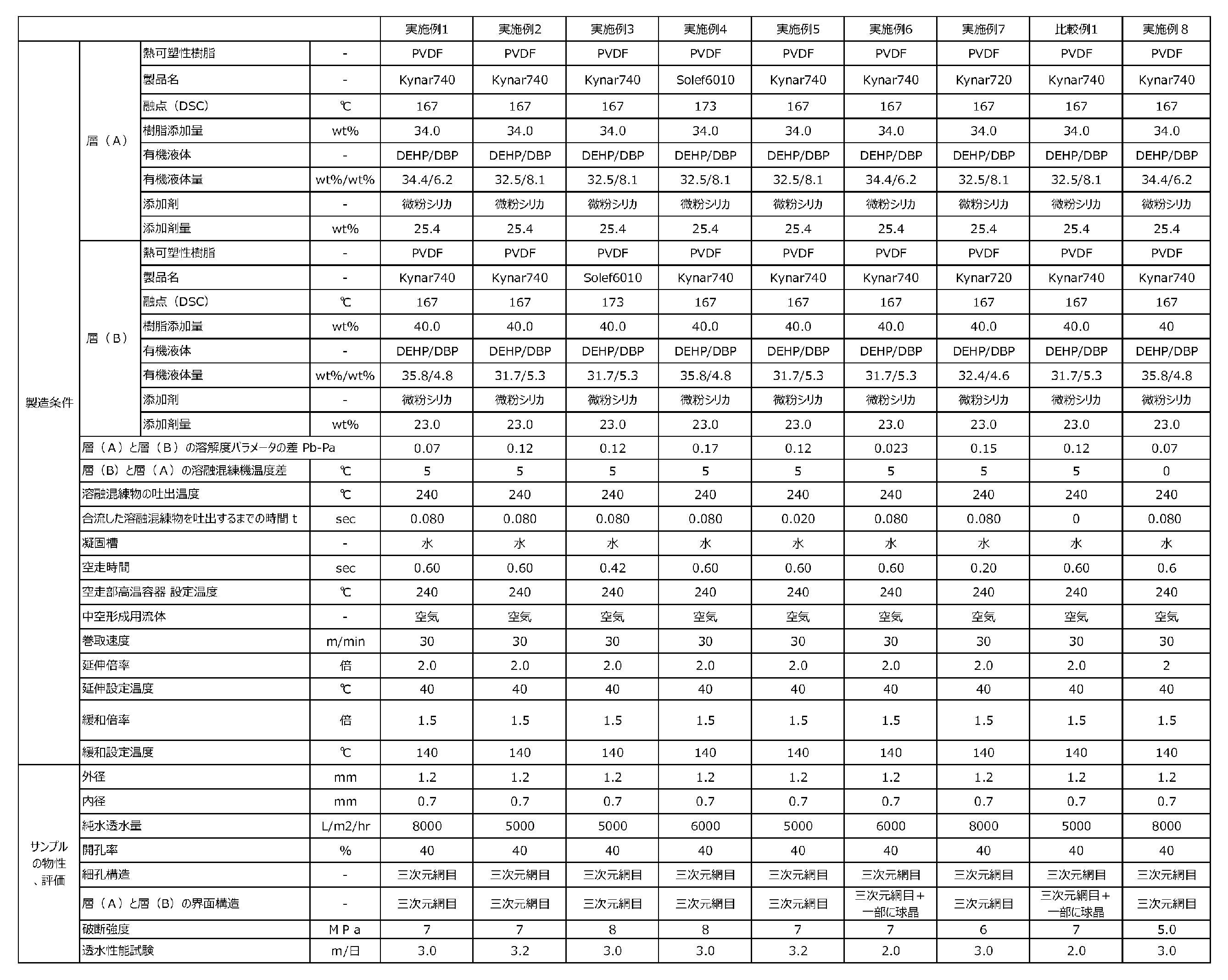
本発明によれば、優れた濾過性能及び強度を有する、孔性多層中空糸膜の製造方法を提供できる。
また、本発明によれば、天然水、生活排水、これらの処理水である懸濁水を除濁する方法において好適に用いることができる、多孔性多層中空糸膜を提供できる。
According to the present invention, it is possible to provide a method for producing a porous multilayer hollow fiber membrane having excellent filtration performance and strength.
Further, according to the present invention, it is possible to provide a porous multilayer hollow fiber membrane that can be suitably used in a method for removing turbidity from natural water, domestic wastewater, and suspended water that is treated water thereof.
Claims (6)
少なくとも一種の溶融混練物が、融点が170℃未満の熱可塑性樹脂を含有し、
前記吐出口内で前記多層多孔性中空糸膜の各層を構成する溶融混練物を合流させた後、合流した溶融混練物を吐出するまでの時間tがt>0秒であることを特徴とする、多孔性多層中空糸膜の製造方法。 A method for producing a multilayer porous hollow fiber membrane with two or more layers, comprising a step of forming a membrane with a multilayer structure by extruding two or more different melt-kneaded materials from a hollow fiber molding nozzle having a discharge port. There it is,
At least one kind of melt-kneaded product contains a thermoplastic resin with a melting point of less than 170°C,
A time t from merging the melt-kneaded materials constituting each layer of the multilayer porous hollow fiber membrane in the discharge port to discharging the merged molten-kneaded material is t>0 seconds, A method for producing a porous multilayer hollow fiber membrane.
前記多孔性多層中空糸膜における被濾過液側の表面である表面FAを含む層を製造する際、下式(1)で表されるポリフッ化ビニリデンの溶解度パラメータと使用する溶媒の溶解度パラメータとの距離をPa、
前記多孔性多層中空糸膜における濾過液側の表面である表面FBを含む層を製造する際、下式(2)で表されるポリフッ化ビニリデンの溶解度パラメータと使用する溶媒の溶解度パラメータとの距離をPb、
としたとき、Pb-Pa>0.05であることを特徴とする、請求項3に記載の多孔性多層中空糸膜の製造方法。
Pa=(4(σdm-σdp)^2+(σpm-σpp)^2+(σhm-σhp)^2)^0.5 ・・・(1)
Pb=(4(σdm-σdp)^2+(σpm-σpp)^2+(σhm-σhp)^2)^0.5 ・・・(2)
[式(1)及び(2)中、σdm及びσdpは、使用する溶媒及びポリフッ化ビニリデンの分散力項をそれぞれ示し、σpm及びσppは、使用する溶媒及びポリフッ化ビニリデンの双極子結合力項をそれぞれ示し、σhm及びσhpは、使用する溶媒及びポリフッ化ビニリデンの水素結合項をそれぞれ示す。] The melt-kneaded material constituting the two inner and outer layers both contain polyvinylidene fluoride,
When manufacturing a layer containing surface FA, which is the surface on the filtrate side of the porous multilayer hollow fiber membrane, the solubility parameter of polyvinylidene fluoride expressed by the following formula (1) and the solubility parameter of the solvent used are The distance is Pa,
When manufacturing a layer including surface FB, which is the surface on the filtrate side of the porous multilayer hollow fiber membrane, the distance between the solubility parameter of polyvinylidene fluoride expressed by the following formula (2) and the solubility parameter of the solvent used. is Pb,
The method for producing a porous multilayer hollow fiber membrane according to claim 3, wherein Pb-Pa>0.05.
Pa=(4(σdm-σdp)^2+(σpm-σpp)^2+(σhm-σhp)^2)^0.5 ...(1)
Pb=(4(σdm-σdp)^2+(σpm-σpp)^2+(σhm-σhp)^2)^0.5 ...(2)
[In formulas (1) and (2), σdm and σdp represent the dispersion force terms of the solvent and polyvinylidene fluoride, respectively, and σpm and σpp represent the dipole binding force terms of the solvent and polyvinylidene fluoride, respectively. σhm and σhp respectively indicate the solvent used and the hydrogen bond term of polyvinylidene fluoride. ]
Applications Claiming Priority (2)
| Application Number | Priority Date | Filing Date | Title |
|---|---|---|---|
| JP2022132092 | 2022-08-22 | ||
| JP2022132092 | 2022-08-22 |
Publications (1)
| Publication Number | Publication Date |
|---|---|
| JP2024029746A true JP2024029746A (en) | 2024-03-06 |
Family
ID=89956707
Family Applications (1)
| Application Number | Title | Priority Date | Filing Date |
|---|---|---|---|
| JP2023108867A Pending JP2024029746A (en) | 2022-08-22 | 2023-06-30 | Method for producing multilayer porous hollow fiber membrane and porous hollow fiber membrane |
Country Status (3)
| Country | Link |
|---|---|
| JP (1) | JP2024029746A (en) |
| CN (1) | CN117599618A (en) |
| CA (1) | CA3209503C (en) |
Family Cites Families (2)
| Publication number | Priority date | Publication date | Assignee | Title |
|---|---|---|---|---|
| JP4563457B2 (en) * | 2005-10-13 | 2010-10-13 | 旭化成ケミカルズ株式会社 | Porous multilayer hollow fiber membrane and method for producing the same |
| US11654400B2 (en) * | 2016-11-09 | 2023-05-23 | Asahi Kasei Kabushiki Kaisha | Porous hollow fiber membrane and method for producing porous hollow fiber membrane |
-
2023
- 2023-06-30 JP JP2023108867A patent/JP2024029746A/en active Pending
- 2023-08-16 CA CA3209503A patent/CA3209503C/en active Active
- 2023-08-22 CN CN202311063668.6A patent/CN117599618A/en active Pending
Also Published As
| Publication number | Publication date |
|---|---|
| CA3209503A1 (en) | 2024-02-22 |
| CN117599618A (en) | 2024-02-27 |
| CA3209503C (en) | 2025-05-13 |
Similar Documents
| Publication | Publication Date | Title |
|---|---|---|
| JP5717987B2 (en) | Porous multilayer hollow fiber membrane | |
| JP4043364B2 (en) | Method for producing hollow fiber membrane | |
| KR101372056B1 (en) | Porous vinylidene fluoride resin membrane and process for producing same | |
| JP6824284B2 (en) | Method for manufacturing porous hollow fiber membrane and porous hollow fiber membrane | |
| US11338253B2 (en) | Porous hollow fiber membrane, method for producing same, and water purification method | |
| KR20060134157A (en) | Polyvinylidene fluoride resin hollow fiber porous filter membrane and manufacturing method thereof | |
| WO2005032700A1 (en) | Vinylidene fluoride based resin porous hollow yarn and method for production thereof | |
| JP2024107332A (en) | Porous membrane | |
| JP5546993B2 (en) | Manufacturing method of irregular porous hollow fiber membrane, irregular porous hollow fiber membrane, module using irregular porous hollow fiber membrane, filtration device using irregular porous hollow fiber membrane, and filtration using irregular porous hollow fiber membrane Method | |
| CA3209503C (en) | Production method for multilayer porous hollow fiber membrane, and porous hollow fiber membrane | |
| JP6097818B2 (en) | Porous hollow fiber membrane and method for producing porous hollow fiber membrane | |
| JP2024022485A (en) | Method for manufacturing porous membrane | |
| WO2011027878A1 (en) | Porous vinylidene fluoride resin membrane and process for producing same | |
| JP2025007450A (en) | Porous hollow fiber membrane | |
| JP2024076877A (en) | Porous membrane and method for producing the same | |
| US20250161883A1 (en) | Porous hollow fiber membrane and method for producing porous hollow fiber membrane | |
| WO2025075101A1 (en) | Porous hollow fiber membrane and method for producing porous hollow fiber membrane | |
| JP2024167047A (en) | Porous membrane, method for producing porous membrane, method for producing sugar solution using porous membrane, and filtration method using porous membrane |