JP2024029725A - bookend with gap - Google Patents
bookend with gap Download PDFInfo
- Publication number
- JP2024029725A JP2024029725A JP2022142575A JP2022142575A JP2024029725A JP 2024029725 A JP2024029725 A JP 2024029725A JP 2022142575 A JP2022142575 A JP 2022142575A JP 2022142575 A JP2022142575 A JP 2022142575A JP 2024029725 A JP2024029725 A JP 2024029725A
- Authority
- JP
- Japan
- Prior art keywords
- bookend
- gap
- bottom plate
- gaps
- bookends
- Prior art date
- Legal status (The legal status is an assumption and is not a legal conclusion. Google has not performed a legal analysis and makes no representation as to the accuracy of the status listed.)
- Pending
Links
Images


Landscapes
- Warehouses Or Storage Devices (AREA)
Abstract
Description
本発明は、垂直に立てた複数の本が倒れないように支える隙間付きブックエンドに関するものである。 The present invention relates to a bookend with a gap that supports a plurality of vertically erected books so that they do not fall over.
従来、複数の本を垂直に立てて横方向に並べた場合、本が倒れないように左右から支える文房具があった。 In the past, when multiple books were placed vertically and lined up horizontally, there were stationery items that supported the books from both sides to prevent them from falling over.
それには次のような問題点があった。
垂直に立てて背表紙を手前にそろえて横方向に並べた複数の本を一対のブックエンドで左右から挟んで支えた場合、一方のブックエンドに本が倒れようとする過重な力が加わると他方のブックエンドと関係なく、前記一方のブックエンドだけが本と一緒に倒れる場合があり、不安定であった。
本発明は以上の問題点を解決するものである。 It had the following problems.
When multiple books are placed vertically and lined up horizontally with their spines aligned towards you and supported by sandwiching them from the left and right between a pair of bookends, if excessive force is applied to one bookend to cause the books to fall over, There were cases where only one bookend fell down along with the book, regardless of the other bookend, resulting in instability.
The present invention solves the above problems.
ブックエンドの側板内辺に突起を設け、前記突起と底板後部及び底板長尺部との間に隙間を設け、向かい合う対となるもう一方のブックエンドの底板長尺部を前記隙間に挿入し、摺動できるようにする。
以上を特徴とする隙間付きブックエンドである。 Providing a protrusion on the inner side of the side plate of the bookend, providing a gap between the protrusion and the rear part of the bottom plate and the long part of the bottom plate, and inserting the long part of the bottom plate of the other opposing pair of bookends into the gap, Allow it to slide.
This is a bookend with a gap that has the above features.
一対の隙間付きブックエンドで挟んだ一冊もしくは複数の本がバランスを崩して倒れそうになって、一方の前記隙間付きブックエンドが寄りかかってきた前記本の為に倒れそうになった場合、一対の前記隙間付きブックエンドがお互いを支え合って倒れることを防ぎ、安定して本を挟むことができる。 If one or more books sandwiched between a pair of bookends with a gap lose their balance and are about to fall, and one of the bookends with a gap is about to fall because of the book leaning against it, The pair of bookends with gaps support each other to prevent them from falling down, and the book can be stably held between them.
))
以下、本発明の実施の形態について説明する。
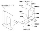
図1、図2に示すように、一枚の金属板の中央部を逆U字状に打ち抜き、その際逆U字状の下部の一辺は打ち抜かず周辺部とつながったままとする。打ち抜いた逆U字状部分を囲む残り三方の周辺部を側板(2)として垂直に折り曲げ、逆U字状部分は底板長尺部(4)として水平に設置し、前記底板長尺部(4)に連続する残る一方の周辺部も底板後部(3)として水平に設置して隙間付きブックエンド(1)とする。 Embodiments of the present invention will be described below.
As shown in FIGS. 1 and 2, the central part of a metal plate is punched out in an inverted U shape, and at this time, one side of the lower part of the inverted U shape is not punched out and remains connected to the peripheral part. The remaining three peripheral parts surrounding the punched inverted U-shaped part are bent vertically as side plates (2), and the inverted U-shaped part is installed horizontally as a bottom plate long part (4). ) is also installed horizontally as the rear part of the bottom plate (3) to form a bookend with a gap (1).
隙間付きブックエンド(1)の側板(2)の空間部(5)中央に向けて、側板内辺(8)に二つの突起(6)を向かい合わせに左右対称に設ける。前期二つの突起(6)は金属板を底板長尺部(4)として逆U字状に打ち抜いて形成する際に、前記突起(6)部分と相似形で前記突起(6)部分に向かい合う位置に前記底板長尺部(4)部分を凹部(9)にして形成する。 Two protrusions (6) are provided symmetrically on the inner side (8) of the side plate facing toward the center of the space (5) of the side plate (2) of the bookend (1) with a gap. The first two protrusions (6) are similar in shape to the protrusion (6) and are positioned opposite to the protrusion (6) when the metal plate is punched out in an inverted U shape as the bottom plate long part (4). The long portion (4) of the bottom plate is formed as a recess (9).
垂直に立った側板(2)に設けた二つの突起(6)の下辺と水平に設置された底板後部(3)及び底板長尺部(4)の上面との間に隙間(7)を設ける。 A gap (7) is provided between the lower sides of the two protrusions (6) provided on the vertically standing side plate (2) and the upper surfaces of the horizontally installed rear part of the bottom plate (3) and the long part of the bottom plate (4). .
二つの突起(6)の下辺に設けた左右二つの隙間(7)は、対となるもう一方の隙間付きブックエンド(1)の底板長尺部(4)を挿入する為の前記二つの隙間(7)を両端とする一つの差込口として機能する。 The two left and right gaps (7) provided on the lower sides of the two protrusions (6) are the two gaps for inserting the bottom plate long part (4) of the other pair of gapped bookends (1). It functions as one outlet with (7) as both ends.
底板長尺部(4)が左右二つの隙間(7)の中を容易に摺動できるように左右二つの隙間(7)の高さは挿入する前記底板長尺部(4)の厚みより若干高く設定し、前記左右二つの隙間(7)の向かい合う空間の合計幅は前記底板長尺部(4)の幅より若干広く設定する。
本発明は以上のような構成である。 The height of the two left and right gaps (7) is slightly larger than the thickness of the bottom plate long part (4) to be inserted so that the bottom plate long part (4) can easily slide through the two left and right gaps (7). The total width of the opposing spaces of the two left and right gaps (7) is set to be slightly wider than the width of the bottom plate elongated portion (4).
The present invention has the above configuration.
本発明を使用するときは、図2、図3に示すように、一対になった二つの隙間付きブックエンド(1)の底板長尺部(4)を向かい合わせにして重ね、重ねて上に乗った一方の隙間付きブックエンド(1)の底板長尺部(4)を重ねて下になった他方の隙間付きブックエンド(1)の左右二つの隙間(7)に同時に挿入する。 When using the present invention, as shown in FIGS. 2 and 3, the bottom plate elongated portions (4) of a pair of two gapped bookends (1) are stacked facing each other, and then stacked on top of each other. The bottom plate elongated part (4) of one bookend with a gap (1) placed on top of the other is inserted simultaneously into the two left and right gaps (7) of the other bookend with a gap (1) placed below.
底板長尺部(4)の先端から凹部(9)の手前までの部分は幅が一定であり、前記一定幅の部分の長さを限度として前記底板長尺部(4)が対となるもう一方の隙間付きブックエンド(1)の左右二つの隙間(7)の中を摺動する際、前記底板長尺部(4)の一定幅の部分は前記左右二つの隙間(7)の中から外れることなく安定して往復できる。 The width of the portion from the tip of the bottom plate elongated portion (4) to the front of the recessed portion (9) is constant, and the length of the portion of the constant width is the limit when the bottom plate elongated portion (4) becomes a pair. When sliding through the two left and right gaps (7) of one bookend with a gap (1), the constant width portion of the bottom plate elongated portion (4) slides through the two left and right gaps (7). It can be reciprocated stably without coming off.
重ねて上になっている隙間付きブックエンド(1)の底板長尺部(4)を重ねて下になっている隙間付きブックエンド(1)の左右二つの隙間(7)に挿入することで直立した二つの側板(2)が向かい合うことになり、向かい合った前記二つの側板(2)の間に図3に示すように垂直に立てた一冊以上の複数の本(10)を並べて置く。 By inserting the bottom plate long part (4) of the stacked upper bookend with gaps (1) into the two left and right gaps (7) of the stacked lower bookend with gaps (1). Two upright side plates (2) face each other, and one or more books (10) standing vertically are placed side by side between the two opposed side plates (2) as shown in FIG.
左右二つの隙間(7)に差し込んだ底板長尺部(4)を摺動させて前記二つの側板(2)を接近させることにより、垂直に立てて並べた本(10)を前記二つの側板(2)で挟むことになり、安定して前記本(10)を保持することができる。 By sliding the bottom plate long part (4) inserted into the two left and right gaps (7) and bringing the two side plates (2) closer together, the books (10) arranged vertically can be moved between the two side plates. (2), the book (10) can be stably held.
重なって上に乗っている隙間付きブックエンド(1)の底板長尺部(4)が重なって下になっている隙間付きブックエンド(1)の左右二つの隙間(7)に挿入されていることにより、前記底板長尺部(4)は前記左右二つの隙間(7)の狭い空間の中で上下左右及びねじれの動きを制限され、往復する摺動の動きのみ自由となる。 The long bottom plate (4) of the overlapping bookend with gaps (1) is inserted into the two left and right gaps (7) of the overlapping bookend with gaps (1) on the bottom. As a result, the bottom plate elongated portion (4) is restricted from vertical, horizontal and torsional movements within the narrow space of the two left and right gaps (7), and is free only from reciprocating sliding movements.
同様に、重なって下になっている隙間付きブックエンド(1)の左右二つの隙間(7)の狭い空間に、重なって上に乗っている隙間付きブックエンド(1)の底板長尺部(4)が挿入されているために、下になっている前記隙間付きブックエンド(1)は上下左右及びねじれの動きが制限され、往復する摺動の動きのみ自由となる。 Similarly, in the narrow space of the two left and right gaps (7) of the bookend with a gap (1) that overlaps and is on the bottom, the long bottom plate of the bookend with a gap (1) that overlaps and rests on top ( 4) is inserted, the lower bookend with a gap (1) is restricted in its vertical, horizontal and torsional movements, and is free only in reciprocating sliding movements.
重なって上に乗っている隙間付きブックエンド(1)が、バランスを崩して倒れようとする本(10)から過重な力を受けて一緒に倒れそうになった場合、前記隙間付きブックエンド(1)の底板長尺部(4)が重なって下になっている隙間付きブックエンド(1)の左右二つの隙間(7)に挿入されていることにより重なって上に乗っている隙間付きブックエンド(1)の動きが制限され、重なって上に乗っている隙間付きブックエンド(1)が横倒しになろうとする動きや、前記底板長尺部(4)の先端が跳ね上がろうとする動きを抑制する。 If the bookend with a gap (1) that is stacked on top of each other receives excessive force from the book (10) that is about to lose its balance and fall over, the bookend with a gap (1) The long part of the bottom plate (4) of 1) is inserted into the two gaps (7) on the left and right of the bookend with gaps (1) that overlaps and lies on top of the bookend with gaps (1). The movement of the end (1) is restricted, and the overlapping bookend (1) with gaps tends to fall sideways, or the tip of the long bottom plate (4) tries to jump up. suppress.
又、重なって下になっている隙間付きブックエンド(1)がバランスを崩して倒れようとする本(10)から過重な力を受けて一緒に倒れそうになった場合、前記隙間付きブックエンド(1)の左右二つの隙間(7)には重なって上に乗っている隙間付きブックエンド(1)の底板長尺部(4)が挿入されていることにより重なって下になっている隙間付きブックエンド(1)の動きが制限され、重なって下になっている隙間付きブックエンド(1)が横倒しになろうとする動きや、重なって下になっている隙間付きブックエンド(1)の底板長尺部(4)が跳ね上がろうとする動きを抑制する。 In addition, if the bookend with a gap (1) that is stacked on top of each other and is on the bottom loses its balance and is about to fall down due to excessive force from the book (10), the bookend with a gap The bottom plate elongated part (4) of the bookend with a gap (1) that overlaps and rides on top is inserted into the two gaps (7) on the left and right of (1), resulting in a gap that overlaps and becomes lower. The movement of the bookend with a gap (1) is restricted, and the bookend with a gap (1) that overlaps and is on the bottom is likely to fall sideways, and the bookend with a gap (1) that is overlapped and is on the bottom. The movement of the bottom plate elongated part (4) to jump up is suppressed.
故に一対の隙間付きブックエンド(1)の二つの側板(2)で挟んだ本(10)から倒れようとする過重な力を一対の隙間付きブックエンド(1)のどちらが受けても、一対の隙間付きブックエンド(1)がお互いの動きを抑制し、又支え合って二つの側板(2)で挟んだ前記本(10)をより安定して挟んで保持することができる。 Therefore, no matter which of the pair of gapped bookends (1) receives the excessive force of the book (10) sandwiched between the two side plates (2) of the pair of gapped bookends (1), the pair of gapped bookends (1) The bookends (1) with gaps suppress each other's movement, and support each other so that the book (10) sandwiched between the two side plates (2) can be more stably sandwiched and held.
1 隙間付ブックエンド
2 側板
3 底板後部
4 底板長尺部
5 空間部
6 突起
7 隙間
8 側板内辺
9 凹部
10 本 1 Bookend with gap 2 Side plate 3 Rear part of bottom plate 4 Long part of bottom plate 5 Space 6 Projection 7 Gap 8 Inner side of side plate 9 Recess 10 pieces
Claims (1)
Priority Applications (1)
| Application Number | Priority Date | Filing Date | Title |
|---|---|---|---|
| JP2022142575A JP2024029725A (en) | 2022-08-22 | 2022-08-22 | bookend with gap |
Applications Claiming Priority (1)
| Application Number | Priority Date | Filing Date | Title |
|---|---|---|---|
| JP2022142575A JP2024029725A (en) | 2022-08-22 | 2022-08-22 | bookend with gap |
Publications (1)
| Publication Number | Publication Date |
|---|---|
| JP2024029725A true JP2024029725A (en) | 2024-03-06 |
Family
ID=90104977
Family Applications (1)
| Application Number | Title | Priority Date | Filing Date |
|---|---|---|---|
| JP2022142575A Pending JP2024029725A (en) | 2022-08-22 | 2022-08-22 | bookend with gap |
Country Status (1)
| Country | Link |
|---|---|
| JP (1) | JP2024029725A (en) |
Citations (4)
| Publication number | Priority date | Publication date | Assignee | Title |
|---|---|---|---|---|
| JPS58175743U (en) * | 1982-05-19 | 1983-11-24 | 棚橋 弘 | Combination bookend |
| JPS62107736U (en) * | 1985-12-24 | 1987-07-09 | ||
| JPH0531012A (en) * | 1991-07-31 | 1993-02-09 | Karl Jimuki Kk | Bookend |
| US20020125201A1 (en) * | 2001-02-20 | 2002-09-12 | Lamming Michael W. | Bookend with slider/joiner |
-
2022
- 2022-08-22 JP JP2022142575A patent/JP2024029725A/en active Pending
Patent Citations (4)
| Publication number | Priority date | Publication date | Assignee | Title |
|---|---|---|---|---|
| JPS58175743U (en) * | 1982-05-19 | 1983-11-24 | 棚橋 弘 | Combination bookend |
| JPS62107736U (en) * | 1985-12-24 | 1987-07-09 | ||
| JPH0531012A (en) * | 1991-07-31 | 1993-02-09 | Karl Jimuki Kk | Bookend |
| US20020125201A1 (en) * | 2001-02-20 | 2002-09-12 | Lamming Michael W. | Bookend with slider/joiner |
Similar Documents
| Publication | Publication Date | Title |
|---|---|---|
| US4410093A (en) | Device for organizing papers and files | |
| US3269547A (en) | Sectional desk organizer | |
| JP2024029725A (en) | bookend with gap | |
| KR101247040B1 (en) | Expandable partition | |
| JP5419552B2 (en) | Unit bookcase | |
| US3944080A (en) | Hanging file folder support structure | |
| JP7201392B2 (en) | bookends | |
| US11072198B1 (en) | Modular paper organizer | |
| US3301408A (en) | Shelf construction | |
| US20050274681A1 (en) | Adjustable width bookend construction | |
| JP3157892U (en) | Bookcase pedestal | |
| JP2014004147A (en) | Desk-side bookshelf | |
| CN208640020U (en) | A random divider panel assembly | |
| KR200463696Y1 (en) | Book-end | |
| KR200378394Y1 (en) | Bookrack | |
| KR200410535Y1 (en) | Shelf height variable shelf | |
| KR200363442Y1 (en) | Bookend assembly | |
| JP3207839U (en) | File end prevention book end | |
| US2885085A (en) | Shelf file | |
| CN208510358U (en) | A kind of toughness is high and is not susceptible to the fixed book end of accounting bookkeeping book of deformation | |
| KR200427162Y1 (en) | Removable dividers for bookshelves | |
| CN216494559U (en) | Snack exhibition cabinet convenient to dismantle installation | |
| CN215304045U (en) | Multifunctional bookshelf | |
| CN211021956U (en) | Outdoor books and newspapers retail cabinet | |
| JP7746618B1 (en) | Retractable bookcase |
Legal Events
| Date | Code | Title | Description |
|---|---|---|---|
| A621 | Written request for application examination |
Free format text: JAPANESE INTERMEDIATE CODE: A621 Effective date: 20250707 |
|
| A977 | Report on retrieval |
Free format text: JAPANESE INTERMEDIATE CODE: A971007 Effective date: 20260130 |
|
| A131 | Notification of reasons for refusal |
Free format text: JAPANESE INTERMEDIATE CODE: A131 Effective date: 20260210 |