JP2024002631A - Image processing device, imaging apparatus, image processing method, computer program, and recording medium - Google Patents
Image processing device, imaging apparatus, image processing method, computer program, and recording medium Download PDFInfo
- Publication number
- JP2024002631A JP2024002631A JP2022101954A JP2022101954A JP2024002631A JP 2024002631 A JP2024002631 A JP 2024002631A JP 2022101954 A JP2022101954 A JP 2022101954A JP 2022101954 A JP2022101954 A JP 2022101954A JP 2024002631 A JP2024002631 A JP 2024002631A
- Authority
- JP
- Japan
- Prior art keywords
- image
- images
- correction
- image processing
- compositing
- Prior art date
- Legal status (The legal status is an assumption and is not a legal conclusion. Google has not performed a legal analysis and makes no representation as to the accuracy of the status listed.)
- Pending
Links
- 238000003384 imaging method Methods 0.000 title claims description 55
- 238000004590 computer program Methods 0.000 title claims 2
- 238000003672 processing method Methods 0.000 title claims 2
- 230000015572 biosynthetic process Effects 0.000 claims abstract description 14
- 238000003786 synthesis reaction Methods 0.000 claims abstract description 14
- 230000002194 synthesizing effect Effects 0.000 claims abstract description 6
- 239000002131 composite material Substances 0.000 claims description 23
- 239000000203 mixture Substances 0.000 claims description 17
- 230000003287 optical effect Effects 0.000 claims description 12
- 238000005520 cutting process Methods 0.000 claims description 4
- 238000000034 method Methods 0.000 abstract description 23
- 238000010586 diagram Methods 0.000 description 19
- 230000006870 function Effects 0.000 description 10
- 230000008569 process Effects 0.000 description 10
- 230000008859 change Effects 0.000 description 6
- 230000029058 respiratory gaseous exchange Effects 0.000 description 6
- 230000009466 transformation Effects 0.000 description 6
- 238000006243 chemical reaction Methods 0.000 description 3
- 238000004364 calculation method Methods 0.000 description 2
- 230000000694 effects Effects 0.000 description 2
- 239000011159 matrix material Substances 0.000 description 2
- 230000009467 reduction Effects 0.000 description 2
- PXFBZOLANLWPMH-UHFFFAOYSA-N 16-Epiaffinine Natural products C1C(C2=CC=CC=C2N2)=C2C(=O)CC2C(=CC)CN(C)C1C2CO PXFBZOLANLWPMH-UHFFFAOYSA-N 0.000 description 1
- 230000003213 activating effect Effects 0.000 description 1
- 230000006835 compression Effects 0.000 description 1
- 238000007906 compression Methods 0.000 description 1
- 230000007423 decrease Effects 0.000 description 1
- 238000003708 edge detection Methods 0.000 description 1
- 238000001914 filtration Methods 0.000 description 1
- 239000004973 liquid crystal related substance Substances 0.000 description 1
- 238000005259 measurement Methods 0.000 description 1
- 230000007246 mechanism Effects 0.000 description 1
- 230000007704 transition Effects 0.000 description 1
Images


Classifications
-
- H—ELECTRICITY
- H04—ELECTRIC COMMUNICATION TECHNIQUE
- H04N—PICTORIAL COMMUNICATION, e.g. TELEVISION
- H04N23/00—Cameras or camera modules comprising electronic image sensors; Control thereof
- H04N23/60—Control of cameras or camera modules
- H04N23/67—Focus control based on electronic image sensor signals
-
- G06T5/80—
-
- G—PHYSICS
- G06—COMPUTING; CALCULATING OR COUNTING
- G06T—IMAGE DATA PROCESSING OR GENERATION, IN GENERAL
- G06T5/00—Image enhancement or restoration
- G06T5/50—Image enhancement or restoration by the use of more than one image, e.g. averaging, subtraction
-
- H—ELECTRICITY
- H04—ELECTRIC COMMUNICATION TECHNIQUE
- H04N—PICTORIAL COMMUNICATION, e.g. TELEVISION
- H04N23/00—Cameras or camera modules comprising electronic image sensors; Control thereof
- H04N23/60—Control of cameras or camera modules
- H04N23/63—Control of cameras or camera modules by using electronic viewfinders
- H04N23/631—Graphical user interfaces [GUI] specially adapted for controlling image capture or setting capture parameters
-
- H—ELECTRICITY
- H04—ELECTRIC COMMUNICATION TECHNIQUE
- H04N—PICTORIAL COMMUNICATION, e.g. TELEVISION
- H04N23/00—Cameras or camera modules comprising electronic image sensors; Control thereof
- H04N23/60—Control of cameras or camera modules
- H04N23/63—Control of cameras or camera modules by using electronic viewfinders
- H04N23/633—Control of cameras or camera modules by using electronic viewfinders for displaying additional information relating to control or operation of the camera
-
- H—ELECTRICITY
- H04—ELECTRIC COMMUNICATION TECHNIQUE
- H04N—PICTORIAL COMMUNICATION, e.g. TELEVISION
- H04N23/00—Cameras or camera modules comprising electronic image sensors; Control thereof
- H04N23/60—Control of cameras or camera modules
- H04N23/67—Focus control based on electronic image sensor signals
- H04N23/676—Bracketing for image capture at varying focusing conditions
-
- H—ELECTRICITY
- H04—ELECTRIC COMMUNICATION TECHNIQUE
- H04N—PICTORIAL COMMUNICATION, e.g. TELEVISION
- H04N23/00—Cameras or camera modules comprising electronic image sensors; Control thereof
- H04N23/80—Camera processing pipelines; Components thereof
-
- H—ELECTRICITY
- H04—ELECTRIC COMMUNICATION TECHNIQUE
- H04N—PICTORIAL COMMUNICATION, e.g. TELEVISION
- H04N23/00—Cameras or camera modules comprising electronic image sensors; Control thereof
- H04N23/95—Computational photography systems, e.g. light-field imaging systems
-
- H—ELECTRICITY
- H04—ELECTRIC COMMUNICATION TECHNIQUE
- H04N—PICTORIAL COMMUNICATION, e.g. TELEVISION
- H04N5/00—Details of television systems
- H04N5/222—Studio circuitry; Studio devices; Studio equipment
- H04N5/262—Studio circuits, e.g. for mixing, switching-over, change of character of image, other special effects ; Cameras specially adapted for the electronic generation of special effects
- H04N5/265—Mixing
-
- G—PHYSICS
- G06—COMPUTING; CALCULATING OR COUNTING
- G06T—IMAGE DATA PROCESSING OR GENERATION, IN GENERAL
- G06T2207/00—Indexing scheme for image analysis or image enhancement
- G06T2207/10—Image acquisition modality
- G06T2207/10141—Special mode during image acquisition
- G06T2207/10148—Varying focus
-
- G—PHYSICS
- G06—COMPUTING; CALCULATING OR COUNTING
- G06T—IMAGE DATA PROCESSING OR GENERATION, IN GENERAL
- G06T2207/00—Indexing scheme for image analysis or image enhancement
- G06T2207/20—Special algorithmic details
- G06T2207/20212—Image combination
- G06T2207/20221—Image fusion; Image merging
Abstract
Description
本発明は、画像処理装置に関するものであり、特にピント位置の異なる複数の画像を表示する画像処理装置に関するものである。 The present invention relates to an image processing device, and particularly to an image processing device that displays a plurality of images with different focus positions.
特許文献1には、被写体に対して、ピント位置を変えながら複数の画像を撮像し、ピント位置が異なる複数の画像を生成する、いわゆるフォーカスブラケットの技術が開示されている。
しかしながら、フォーカスブラケットの技術では、たとえピント位置以外の設定を変えずに複数の画像を撮像するとしても、撮像で得られた複数の画像の間の画角が変わってしまう課題がある。 However, the focus bracketing technique has a problem in that even if multiple images are captured without changing settings other than the focus position, the angle of view between the captured images changes.
本発明は、上記の課題を鑑みてなされたものであり、フォーカスブラケットの撮像で得られた画像の画角を補正する画像処理装置を提供することを目的とする。 The present invention has been made in view of the above problems, and an object of the present invention is to provide an image processing device that corrects the angle of view of an image obtained by focus bracketing.
本発明は、ピント位置の異なる複数の画像に対して、合成を行う合成手段と、前記複数の画像に対して、画角の補正を行う補正手段と、前記補正手段が前記補正を行う場合、前記補正を行った後の画像を表示する表示手段と、を有し、前記合成手段が前記合成を行う場合、前記補正手段が前記補正を行い、前記合成手段が前記合成を行わない場合、前記補正手段が前記補正を行わない画像処理装置を提供する。 The present invention provides a composition means that performs composition on a plurality of images having different focus positions, a correction means that performs angle of view correction on the plurality of images, and a case where the correction means performs the correction; display means for displaying the image after performing the correction; when the composition means performs the composition, the correction means performs the correction; when the composition means does not perform the composition, the An image processing device in which a correction means does not perform the above correction is provided.
本発明の画像処理装置によれば、ユーザの設定などに応じて、フォーカスブラケットの撮像で得られた画像の画角を補正できる。 According to the image processing device of the present invention, the angle of view of an image obtained by focus bracketing imaging can be corrected according to the user's settings and the like.
以下では、添付の図面を参照しながら、本発明の好適な実施形態について詳細に説明する。 Hereinafter, preferred embodiments of the present invention will be described in detail with reference to the accompanying drawings.
<デジタルカメラの概要>
図1は本実施形態に係る画像の撮像のためのデジタルカメラの構造を示すブロック図の一例である。デジタルカメラ100は、静止画を撮像することができ、かつ、合焦位置の情報を記録し、コントラスト値の算出および画像の合成などが可能なものである。さらに、デジタルカメラ100は、撮像して保存した画像、または、外部から入力した画像に対して、拡大処理または縮小処理を行うことができる。
<Overview of digital cameras>
FIG. 1 is an example of a block diagram showing the structure of a digital camera for capturing images according to this embodiment. The
制御部101は、例えばCPUやMPUなどのシグナルプロセッサであり、予め後述するROM105に内蔵されたプログラムを読み出しながら、デジタルカメラ100の各部分を制御する。たとえば、後述するように、制御部101が、後述する撮像部104に対して撮像の開始と終了について指令を出す。または、後述する画像処理部107に対して、ROM105に内蔵されたプログラムに基づいて、画像処理の指令を出す。ユーザによる指令は、後述する操作部110によってデジタルカメラ100に入力され、制御部101を通して、デジタルカメラ100の各部分に達する。
The
駆動部102は、モーターなどによって構成され、制御部101の指令の下で、後述する光学系103を機械的に動作させる。たとえば、制御部101の指令に基づいて、駆動部102が光学系103に含まれるフォーカスレンズの位置を移動させ、光学系103の焦点距離を調整する。
The
光学系103は、ズームレンズ、フォーカスレンズ、および絞りなどにより構成される。絞りは、透過する光量を調整する機構である。レンズの位置を変えることによって、合焦位置を変えることができる。
The
撮像部104は、光電変換素子であり、入射された光信号を電気信号に変換する光電変換を行うものである。たとえば、撮像部104に、CCDセンサやCMOSセンサなどを適用することができる。撮像部104は、動画撮像モードを設け、時間的に連続する複数の画像を動画の各々のフレームとして、撮像することができる。
The
ROM105は、記録媒体としての読み出し専用の不揮発性メモリであり、デジタルカメラ100が備える各ブロックの動作プログラムに加え、各ブロックの動作に必要なパラメータ等を記憶している。RAM106は、書き換え可能な揮発性メモリであり、デジタルカメラ100が備える各ブロックの動作において出力されたデータの一時的な記憶領域として用いられる。
The
画像処理部107は、撮像部104から出力された画像、あるいは後述する内蔵メモリ109に記録されている画像信号のデータに対して、ホワイトバランス調整、色補間、フィルタリングなど、様々な画像処理を行う。また、撮像部104が撮像した画像信号のデータに対して、JPEGなどの規格で、圧縮処理を行う。
The
画像処理部107は、特定の処理を行う回路を集めた集積回路(ASIC)で構成される。あるいは、制御部101がROM105から読み出したプログラムに従って処理することで、制御部101が画像処理部107の機能の一部または全部を兼用するようにしてもよい。制御部101が画像処理部107の全ての機能を兼用する場合には、画像処理部107をハードウェアとして有する必要はなくなる。
The
表示部108は、RAM106に一時保存されている画像、または、後述する内蔵メモリ109に保存されている画像、あるいは、デジタルカメラ100の設定画面などを表示するための液晶ディスプレイや有機ELディスプレイなどである。
The
内蔵メモリ109は、撮像部104が撮像した画像や画像処理部107の処理を得た画像、および、画像撮像時の合焦位置の情報などを記録する場所である。内蔵メモリの代わりに、メモリカードなどを用いてもよい。
The built-in
操作部110は、たとえば、デジタルカメラ100につけるボタンやスイッチ、キー、モードダイアルなど、あるいは、表示部108に兼用されるタッチパネルなどである。ユーザによる指令は、操作部110を経由して、制御部101に達する。
The
<被写体結像の説明>
以下では、被写体結像について簡単に説明する。
<Explanation of subject imaging>
Below, object imaging will be briefly explained.
図2は、本実施形態における被写体像が結像面に結像する様子を説明するための図である。 FIG. 2 is a diagram for explaining how a subject image is formed on an imaging plane in this embodiment.
図2(a)は、被写体201が光学レンズ202によって面203a上に像204として結像している様子を示している。すなわち、面203aと撮像部104の撮像センサ面とが互いに一致すれば、被写体201は面203aにて「点」として結像し、合焦画像として記録される。
FIG. 2A shows a state in which a
図2(b)は、像の結像面と撮像センサ面とが一致しない場合を示している。撮像センサ面203bが図2(a)に示される面203aとは異なる位置にある場合、光学レンズ202により結像される被写体201は、錯乱円205として撮像センサ面203b上に写る。図2(b)に示したような状況では、錯乱円205が撮像センサの許容錯乱円よりも小さい場合、錯乱円205は合焦した場合の「点」と同等とみなすことができ、合焦画像と同等の画像が得られる。一方、錯乱円205が許容錯乱円よりも大きい場合、撮像センサ面203bではぼけた画像が得られる。
FIG. 2(b) shows a case where the imaging plane of the image and the imaging sensor plane do not match. When the
図2(c)は、上記の様子を側面から示した図である。ここで、焦点210にて被写体が結像し、面211aの位置に撮像センサ面が存在する場合、錯乱円径212aが得られる。図2(c)に示した錯乱円径212aは、撮像センサの許容錯乱円径213よりも小さい。そのため、撮像センサにて記録される画像217は、ボケの無い合焦画像となる。一方、撮像センサ面が面214aの位置に存在する場合、このときの錯乱円径215aは、許容錯乱円径213よりも大きい。そのため、撮像センサ面214a上の画像218aは、ぼけた画像となる。錯乱円径212aが許容錯乱円径213よりも小さくなる斜線で示される領域は焦点深度216aであり、焦点深度216aを被写体側に換算して置き換えたものが被写界深度となる。
FIG. 2(c) is a side view showing the above situation. Here, when the subject is imaged at the
図2(d)は、図2(c)と比べて、絞りを絞った状態を示す図である。絞りを絞った状態では、入射光の径が奥行きの違いとなるため、面211bに対しての錯乱円径212b、面214bに対しての錯乱円径215bのようにそれぞれ変化する。図2(c)の錯乱円径215aと比較して、図2(d)の錯乱円径215bは小さい。そのため、図2(d)に示した画像218bは、画像218aよりもボケ量の少ない画像となる。また、図2(d)に示した焦点深度216bは、焦点深度216aよりも深い。
FIG. 2(d) is a diagram showing a state in which the aperture is narrowed down compared to FIG. 2(c). When the aperture is closed, the diameter of the incident light differs in depth, so the diameter of the circle of
<フォーカスブリージング>
フォーカスブリージングとは、デジタルカメラを用いて撮像を行うとき、ズームレンズは一切動かさず、フォーカスリングだけ動かしていていても画角が変化してしまう現象である。フォーカスブリージングは、フォーカス群が移動するとき、変倍作用を発揮してしまうことに起因する。とくに近距離にピントを合わせた時、レンズの実焦点距離が大きく変わってしまうことがあり、フォーカスブリージングの減少がより顕著に表れる。
<Focus Breathing>
Focus breathing is a phenomenon in which when taking an image using a digital camera, the angle of view changes even if the zoom lens is not moved at all and only the focus ring is moved. Focus breathing is caused by a magnification change effect when the focus group moves. In particular, when focusing on a short distance, the actual focal length of the lens may change significantly, making the reduction in focus breathing more noticeable.
フォーカスブリージングにより、被写体に対して複数の画像を撮像するとき、ピント位置を変えると、たとえピント位置以外の設定を変更しなくても、画角が変えてしまう可能性がある。フォーカスブラケットの撮像においては、ピント位置を変えただけで、得られた複数の画像の間の画角が異なる可能性がある。 When multiple images of a subject are captured using focus breathing, if the focus position is changed, the angle of view may change even if settings other than the focus position are not changed. In focus bracket imaging, simply changing the focus position may result in different angles of view between the plurality of images obtained.
図3は、本実施形態におけるピント位置と像倍率との関係を示す関数を説明するための図である。図3で示した関数においては、像倍率はピント位置に対して単調減少である。図3に示したようなピント位置と像倍率との関係は、レンズの種類によって異なり、レンズの固有情報としてあらかじめ測定で得られる。また、図3に示したようなピント位置と像倍率との関係から、ピント位置と画角との関係も得られる。なお、ここでいう像倍率は、撮像素子に結像された被写体像の大きさと、実際の被写体の大きさの比を指す。 FIG. 3 is a diagram for explaining a function showing the relationship between the focus position and the image magnification in this embodiment. In the function shown in FIG. 3, the image magnification monotonically decreases with respect to the focus position. The relationship between the focus position and the image magnification as shown in FIG. 3 differs depending on the type of lens, and can be obtained by measurement in advance as unique information of the lens. Further, from the relationship between the focus position and the image magnification as shown in FIG. 3, the relationship between the focus position and the angle of view can also be obtained. Note that the image magnification here refers to the ratio between the size of the subject image formed on the image sensor and the actual size of the subject.
<深度合成の説明>
フォーカスブラケットのひとつの応用例としては、深度合成が挙げられる。
<Explanation of depth compositing>
One application example of focus bracketing is depth compositing.
図4は、本実施形態における深度合成の撮像を説明するための図である。ここでは、合焦させる被写体として、被写体41~43を想定している。それぞれの被写体41~43は、互いに異なる距離(被写体距離)に存在するものとし、デジタルカメラ100に近い側から(近距離側から遠距離側に向かう方向に)被写体41、42、43の順に位置している。複数の被写体41~43のすべてに対して合焦した深度合成画像を得るには、フォーカスブラケット撮像を行う焦点範囲400(ブラケット範囲)を、複数の焦点深度でカバーする必要がある。被写界深度411~416は、それぞれの撮像における焦点深度を示し、焦点範囲300をカバーするように並んでいる。すなわち、被写界深度411~416となるピント位置で撮像(6回の撮像)を行うことにより、焦点範囲400の範囲内の被写体41~43は、いずれかの画像において合焦した状態となる。また、このようにして撮像された複数の画像から、それぞれの撮像における焦点深度内の領域を画像合成することにより、焦点範囲400の全域(ブラケット全域)で合焦した画像を得ることができる。
FIG. 4 is a diagram for explaining imaging for depth compositing in this embodiment. Here, subjects 41 to 43 are assumed to be the subjects to be focused on. It is assumed that the
また、深度合成の技術は、解像感の高い画像を得ることにも有用である。フォーカスブラケットの撮像において、それぞれの画像を撮像するときの被写界深度を浅くすると、合焦領域において極めて解像感の高い画像領域が得られる。それぞれの合焦領域に対して合成を行うと、合成画像でも高い解像感が維持できる。 Further, depth compositing technology is also useful for obtaining high-resolution images. In focus bracket imaging, if the depth of field is made shallow when capturing each image, an image area with extremely high resolution can be obtained in the in-focus area. By performing composition for each focus area, high resolution can be maintained even in the composite image.
次は、本実施形態における深度合成の画像の生成のフローについて説明する。 Next, a flow of image generation for depth synthesis in this embodiment will be described.
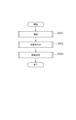
図5は、本実施形態における合成画像の生成について説明するためのフローチャートである。ステップS501では、撮像部104は、光軸方向でのピント位置の異なる複数の画像を撮像する。ステップS502では、制御部101は、ステップS201で撮像部104が撮像した複数の画像に対して位置合わせを行う。ステップS503で、画像処理部107は、位置合わせを行った後の画像に対して合成を行い、被写界深度のより深い合成画像を生成する。
FIG. 5 is a flowchart for explaining generation of a composite image in this embodiment. In step S501, the
以下では、図5に示したそれぞれのステップについて詳細に説明する。 Below, each step shown in FIG. 5 will be explained in detail.
図6は、本実施形態におけるステップS501での撮像について説明するためのフローチャートである。 FIG. 6 is a flowchart for explaining imaging in step S501 in this embodiment.
ステップS601で、制御部101は、撮像の設定を行う。たとえば、ユーザがタッチパネルなどで、合焦したい位置を指定し、制御部101が、ユーザが指定した箇所が最も至近側のピント位置として、順次にあらかじめ定められたピント間隔で、所定の枚数で、ほかのピント位置を特定する。また、制御部101が、ユーザが指定した箇所が最も無限遠側のピント位置としてもよい。
In step S601, the
または、制御部101が、光学系103を通し、自動合焦を利用して最初のピント位置を特定してもよい。
Alternatively, the
または、ユーザがタッチパネルなどで、2つの箇所を指定し、制御部101が、ユーザが指定した箇所を最も無限遠側と最も至近側とのピント位置とする。
Alternatively, the user specifies two locations using a touch panel or the like, and the
ステップS602で、撮像部104は、ステップS301で設定したピント位置のうち、未撮像のものの中で、撮像順番が最も先のピント位置において撮像する。
In step S602, the
ステップS603で、制御部101は、ステップS301で設定したすべてのピント位置において撮像を行ったかどうかについて判断する。すべてのピント位置に撮像した場合は、図6に示したフローチャートでの処理を終了し、まだ撮像していないピント位置があれば、ステップS602に戻る。
In step S603, the
また、撮像部104を複数有する多眼カメラの場合、ステップS601で設定された複数のピント位置で同時に撮像してもよい。
Further, in the case of a multi-lens camera having a plurality of
図7は、本実施形態における深度合成での位置合わせについて説明するためのフローチャートである。 FIG. 7 is a flowchart for explaining alignment in depth synthesis in this embodiment.
ステップS701では、制御部101は、ステップS501で撮像部104が撮像した画像のうちから、位置合わせの基準画像を取得する。位置合わせの基準画像は、たとえば、撮像順番が最も早いものとする。あるいは、ピント位置を変えながら撮像することで、わずかながら撮像された画像間で画角が変化するため、撮像した画像の中で画角が最も狭いものにしてもよい。
In step S701, the
ステップS702では、制御部101は、位置合わせの処理の対象画像を取得する。対象画像は、ステップS701で取得した基準画像以外の画像で、位置合わせの処理が済んでいないものとする。制御部101は、撮像順番が最も早いものを基準画像とするならば、撮像した順番で順次に対象画像を取得すればよい。
In step S702, the
ステップS703では、制御部101は、基準画像と対象画像との位置のずれ量を算出する。算出方法の一例は、以下に述べる。まず、制御部101は、基準画像に、複数のブロックを設定する。制御部101は、各々のブロックのサイズが同じになるように設定することが好ましい。次に、制御部101は、対象画像の、基準画像のそれぞれのブロックと同じ位置に、基準画像のブロックよりも広い範囲を、探索範囲を設定する。最後に、制御部101は、対象画像のそれぞれの探索範囲に、基準画像のブロックとの輝度の差分絶対値和(Sum of Absolute Difference、以下、SADをいう)が最小となる対応点を算出する。制御部101は、基準画像のブロックの中心と前述した対応点から、ステップS703でいう位置のずれをベクトルとして算出する。制御部101は、前述する対応点の算出において、SADのほかに、差分二乗和(Sum of Squared Difference、以下SSDをいう)や正規化相互相関(Normalized Cross Correlation、以下NCCをいう)などを用いてもよい。
In step S703, the
ステップS704で、制御部101で、基準画像と対象画像との位置のずれ量から変換係数を算出する。制御部101は、変換係数として、例えば射影変換係数を用いる。ただし、変換係数として射影変換係数だけに限定するわけではなく、アフィン変換係数や水平垂直シフトのみの簡略化した変換係数を用いてもよい。
In step S704, the
ステップS705で、画像処理部107は、ステップS704で算出した変換係数を用いて対象画像に対して変換を行う。
In step S705, the
たとえば、制御部101は、下記の(式1)に示した式を用いて変形を行うことができる。
For example, the

(式1)では、(x´,y´)は変形を行った後の座標を示し、(x,y)は変形を行う前の座標を示す。行列AはステップS404で制御部101が算出した変形係数を示す。
In (Formula 1), (x', y') indicates the coordinates after the transformation, and (x, y) indicates the coordinates before the transformation. Matrix A indicates the deformation coefficients calculated by the
ステップS706で、制御部101は、基準画像以外のすべての画像に対して位置合わせを行ったかどうかについて判断する。基準画像以外のすべての画像に対して位置合わせを行った場合は、図7に示したフローチャートでの処理を終了し、まだ処理していない画像があれば、ステップS702に戻る。
In step S706, the
また、上述した多眼カメラで撮像された複数の画像を位置合わせする場合、光学系103の位置の違いにより生まれる視差量をステップS703でずれ量算出で求める事が出来るため、同様の処理で位置合わせを行うことが出来る。
Furthermore, when aligning a plurality of images captured by the multi-lens camera described above, the amount of parallax caused by the difference in the position of the
図8は、本実施形態における深度合成の画像の合成について説明するためのフローチャートである。 FIG. 8 is a flowchart for explaining image composition in depth composition according to this embodiment.
ステップS801で、画像処理部107は、位置合わせを行った後のそれぞれの画像(基準画像を含む)に対してコントラスト値を算出する。コントラスト値の算出方法の一例としては、たとえば、まず、画像処理部107は、それぞれの画素の色信号Sr、Sg、Sbから、下記の(式2)を用いて輝度Yを算出する。
Y=0.299Sr+0.587Sg+0.114Sb・・・(式2)
In step S801, the
Y=0.299Sr+0.587Sg+0.114Sb...(Formula 2)
次に、3×3の画素の輝度Yの行列Lに、下記の(式3)ないし(式5)に示したように、ソーベルフィルタを用いてコントラスト値Iを算出する。 Next, a contrast value I is calculated using a Sobel filter on a matrix L of luminance Y of 3×3 pixels as shown in (Equation 3) to (Equation 5) below.


また、上述のコントラスト値の計算方法は一例にすぎず、たとえば、使用するフィルタをラプラシアンフィルタ等のエッジ検出フィルタや所定の帯域を通過するバンドパスフィルタを用いることも可能である。 Further, the above-described contrast value calculation method is only an example, and for example, it is also possible to use an edge detection filter such as a Laplacian filter or a bandpass filter that passes a predetermined band.
ステップS802で、画像処理部107は合成マップを生成する。合成マップの生成方法としては、画像処理部107は、それぞれの画像の同じ位置にある画素のコントラスト値を比較し、コントラスト値の大きさに応じた合成比率を算出する。具体的に、同じ位置にある画像のうち、コントラスト値の最も大きい画素に対して100%の合成比率を与え、同じ位置にある他の画素に対して0%の合成比率を与える。つまり、次の(式6)が成り立つ。
In step S802, the

(式6)では、Cm(x,y)はステップS801で算出したコントラスト値を表し、Am(x,y)は合成マップの比率を表す。なお、mはピント位置の異なる複数画像のうちm番目の画像、xは画像の水平座標、yは垂直座標を示している。
In (Equation 6), Cm (x, y) represents the contrast value calculated in step S801, and Am (x, y) represents the ratio of the composite map. Note that m represents the m-th image among multiple images with different focus positions, x represents the horizontal coordinate of the image, and y represents the vertical coordinate of the image.
ただし、ステップS802では、境界部が不自然にならないように合成比率を適宜調整する必要がある。その結果、1枚の画像における合成マップの合成比率は、0%と100%との二値化のものでなく、連続的に変化するものになる。 However, in step S802, it is necessary to adjust the synthesis ratio as appropriate so that the boundary does not look unnatural. As a result, the synthesis ratio of the synthesis map in one image is not a binary value of 0% and 100%, but is one that changes continuously.
ステップS803で、画像処理部107は、ステップS802で生成した合成マップを用いて、位置合わせの後の画像に対して合成処理を行い、合成画像を生成する。
In step S803, the
<深度合成の合成画像の画角>
前述した深度合成において、ステップS803で得られた合成画像は、ステップS602での撮像で得られた画像と比べて、前述したフォーカスブリージングのため、画角が狭くなる可能性がある。ステップS602で撮像部104が撮像した複数の画像は、ピント位置が変わってしまったため、画角も変わってしまう可能性がある。つまり、ステップS602で撮像部104が撮像した複数の画像の画角が同じでない。画像処理部107がステップS602で撮像部104が撮像した複数の画像を用いて合成画像を生成するとき、最も画角の狭い画像の画角に合わせて合成画像の画角を決定しなければならない。そのため、合成画像の画角は、ステップS602で撮像部104が撮像した複数の画像のうち、画角の最も狭い画像の画角と同じになる。言い換えれば、画角の最も狭い画像以外の画角は、合成画像の画角と異なる。
<Angle of view of composite image of depth compositing>
In the depth composition described above, the composite image obtained in step S803 may have a narrower angle of view than the image obtained in the imaging in step S602 due to the focus breathing described above. Since the focus position of the plurality of images captured by the
上記のように、撮像画像と合成画像との画角の違いは、ユーザが違和を感じることもある。例えば、ユーザがフォーカスブラケットの撮像を行うとき、画角が狭くなる方向で撮像するのであれば、ユーザが最初に表示部108で見た画角と最後に合成で得られた画像の画角と異なる。
As described above, the difference in the angle of view between the captured image and the composite image may make the user feel uncomfortable. For example, when a user performs focus bracketing imaging, if the image is taken in a direction that narrows the angle of view, the angle of view that the user first sees on the
そのため、フォーカスブラケットで得られた複数の画像に対して、画角の最も狭い画像の画角に合わせて画角を補正することが考えられるが、深度合成の処理を行わない場合では、画角を補正しなくてもよい。 Therefore, it is possible to correct the angle of view of multiple images obtained by focus bracketing to match the angle of view of the image with the narrowest angle of view, but if depth compositing processing is not performed, There is no need to correct it.
そこで、本実施形態において、制御部101は、深度合成の処理を行うかどうかに応じて、フォーカスブラケットの撮像で得られる画像に対して画角の補正を行うかどうかを決める。
Therefore, in the present embodiment, the
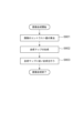
図9は、本実施形態における画角の補正を説明するためのフローチャートである。 FIG. 9 is a flowchart for explaining correction of the angle of view in this embodiment.
ステップS901で、撮像部104は、フォーカスブラケットの撮像を行う。ステップS901での処理は、図6に示したフローと同一だと考えてよい。撮像部104が、決められた複数の異なるピント位置で複数の画像を撮像する。
In step S901, the
ステップS902で、制御部101は、深度合成のモードであるかどうかを判断する。ここいう深度合成のモードであるかどうかを判断することは、デジタルカメラ100の1つの機能としての深度合成が、アクティブな状態であるかどうかを判断する。たとえば、デジタルカメラ100が深度合成のモードのほかに、普通の連写モードなどを有するとすると、普通の連写モードでなく、深度合成のモードが選ばれていることを、制御部101が判断する。
In step S902, the
深度合成のモードである場合、フローがステップS903に進み、ステップS903では、画像処理部107が画角の補正を行う。
If the mode is depth composition, the flow advances to step S903, and in step S903, the
ステップS903での画角の補正の方法としては、一例として画像処理部107が、複数の画像の画角のうち、最も狭い画角を基準にし、ほかの画像に対して切り出し処理を行う。
As an example of a method for correcting the angle of view in step S903, the
図10は、本実施形態における画像の切り出し処理を説明するための図である。画像1001と画像1002とは、フォーカスブラケットの撮像で得られた2枚の画像であるとする。画像1002の画角は、フォーカスブラケットの撮像で得られた画像のうち、最も狭い画角とする。画像処理部107は、画像1002の画角を基準とする。そして、画像処理部107は、画像1001に対して、画像1002の画角に相当する部分1003を切り出す。画像処理部107は、同じような処理を、フォーカスブラケットの撮像で得られた画像1002以外のすべての画像に対して行う。その結果、フォーカスブラケットの撮像で得られたすべての画像が同じ画角を有するようになる。
FIG. 10 is a diagram for explaining image cutting processing in this embodiment. It is assumed that
また、画像処理部107は、実際に撮像した画像の画角を比較しなくても、ピント位置と画角との関係を用いて画角の補正を行ってもよい。前述した通り、ピント位置と像倍率との間に、図3に示した固有的な関係がある。像倍率と画角とは、一定の関係が認められることから、画角とピント位置との間の関係も、レンズの固有情報として得られる。画像処理部107は、レンズの固有情報である画角とピント位置との関係を取得し、フォーカスブラケットの撮像のピント位置を用いて、フォーカスブラケットの撮像で得られた複数の画像の間の画角の相対関係が取得できる。つまり、画像処理部107は、基準となる画像のピント位置と補正対象の画像のピント位置との情報があれば、補正対象の画像の画角の補正を行える。
Furthermore, the
図11は、本実施形態における画像の表示を説明するための図である。図11(a)は、深度合成の画像を生成する場合の表示部108の表示を示している。図11(a)では、深度合成の画像を生成するのに用いられる画像(撮像画像)と合成画像とを同時に表示する様子が示されている。画像処理部107は、表示部108に表示される画像の画角を揃えるための補正を行うと、表示部108に表示される画像の画角が統一される。
FIG. 11 is a diagram for explaining image display in this embodiment. FIG. 11A shows the display on the
図11(b)は、深度合成の画像を表示せず、撮像画像のみ表示する場合の表示部108の表示を示している。図11(b)の場合でも、画像処理部107は、表示部108に表示される画像の画角を揃えるための補正を行うことができる。
FIG. 11(b) shows the display on the
図12は、本実施形態における画像の表示を説明するためのもう1つの図である。図11(a)は、表示部108に撮像画像1が表示されている様子を示す。図11(b)は、表示部108に撮像画像2が表示されている様子を示す。図11(c)は、表示部108に撮像画像15が表示されている様子を示す。図11(d)は、表示部108に合成画像が表示されている様子を示す。
FIG. 12 is another diagram for explaining image display in this embodiment. FIG. 11A shows the captured
ユーザが、操作部110に設けられるキーまたはタッチパネルなどを操作することによって、図11に示したような画面で撮像画像1を選択し、表示部108が図12(a)のような表示に遷移する。同様に、ユーザが、操作部110操作することによって、図11に示したような画面で撮像画像2を選択し、表示部108が図12(b)のような表示に遷移する。また、ユーザが、操作部110操作することによって、図11(a)に示したような画面で撮像画像2を選択し、表示部108が図12(d)のような表示に遷移する。
The user selects captured
また、表示部108が図12のように、1つの画像を表示する状態から、別の1つの画像を表示するように遷移してもよい。たとえば、表示部108は、図12(a)のように、撮像画像1を表示しているとする。ユーザが、操作部110に設けられるキーなどを操作することで、表示部108が図12(b)のように、撮像画像2を表示するように、画像の切り替えを行う。ユーザがさらに、撮像部110を操作することで、順次に撮像画像を表示部108に表示させることができる。表示部108がすべての撮像画像を表示すると、ユーザがさらに操作部110を操作すると、表示部108が合成画像を表示する。
Furthermore, the
なお、図11、図12に示した撮像画像の枚数は、一例に過ぎない。 Note that the number of captured images shown in FIGS. 11 and 12 is only an example.
画像処理部107が撮像画像の画角に対して補正を行わないと、表示部108は、順次に撮像画像を表示している間に、撮像画像の間の画角が変わっているように見える。画像処理部107が撮像画像の画角に対して補正を行うと、表示部108は、順次に撮像画像を表示している間に、撮像画像の間の画角が同一に見える。ユーザから見て、ピント位置による画像間の変化をより顕著に見える。
If the
さらに、ユーザが別の方法を用いて表示部108に表示される画像を選択してもよい。たとえば、デジタルカメラ100の内蔵メモリ109に、フォーカスブラケットで撮像された複数の撮像画像が記録されているとし、デジタルカメラ100の表示部108に兼用されるタッチパネルが操作部110として機能するとする。図13は、本実施形態におけるデジタルカメラ100の表示部108での表示の一例を説明するための図である。図13には、表示部108が、フォーカスブラケットで撮像された複数の撮像画像のうちの任意の1枚の画像を表示している様子を示している。ユーザが、表示部108に兼用されるタッチパネルのエリア1311をタッチすると、表示部108がフォーカスブラケットで撮像された複数の撮像画像のうち、エリア1311が最も合焦している画像を表示する。このように、デジタルカメラ100が、ユーザが指定した領域に合焦する画像を素早く表示できる。
Furthermore, the user may select an image to be displayed on the
上記の画像の表示の切り替え方法は、予め画像の合焦位置の情報を画像とともに内蔵メモリ109に記録することにより実現できる。あるいは以下のような方法で実現できる。
The above-described method of switching the image display can be realized by recording information on the focal position of the image in the built-in
図14は、本実施形態における画像切り替えの一例について説明するための図である。図14に示した画像1401は、図13に示した1301と同じように、フォーカスブラケットで撮像された複数の撮像画像のうちの任意の1枚の画像である。画像1401には、後述する処理のために複数のブロックに分割されている。図14に示したようなブロックの分割は、説明上の便宜のために描かれているものであり、実際の分割は図14に示したものよりはるかに細かい。ユーザがエリア1311に相当する箇所にタッチすると、制御部101は、ユーザがタッチしたエリア1311に相当する斜線のブロック1411を特定する。次に、画像処理部107は、フォーカスブラケットで撮像されたすべての撮像画像の、ブロック1411に相当する複数のブロックから、コントラスト値を算出する。コントラスト値の算出方法は、前述した(式2)ないし(式5)に記載の方法で算出してよい。制御部101は、ブロック1411に相当する複数のブロックのうち、コントラスト値が最も高いブロックが合焦しているものとする。次に、表示部108は、合焦しているブロックを有する撮像画像を表示する。
FIG. 14 is a diagram for explaining an example of image switching in this embodiment. An
以上に述べた方法を用いても、表示部108は、ユーザがタッチした箇所が最も合焦された画像を素早く表示できる。
Even if the method described above is used, the
また、以上の記載におけるユーザがタッチパネルにおけるタッチの操作は、タッチパネルが設けられていないデジタルカメラ100において、操作部110に設けられるボタンやキーなどで等価の操作が実現できる。たとえば、表示部108が、図14に示したように、画像にブロックを表示し、ユーザが、ボタンやキーなどで合焦させたいブロックを順次選択し、確定ボタンで表示部108が合焦させたいブロックが対応する画像を表示するといった実施方法も考えられる。
Further, the user's touch operation on the touch panel in the above description can be equivalently performed using buttons, keys, etc. provided on the
本実施形態によれば、ピント位置の異なる複数の撮像画像に対して、合成の実施有無に応じて、撮像画像を表示するときに画角を補正するかどうかを決めることができる。 According to the present embodiment, it is possible to determine whether to correct the angle of view when displaying a plurality of captured images having different focus positions, depending on whether or not compositing is performed.
(その他の実施形態)
なお、上記実施形態においては、個人向けのデジタルカメラをもとに説明を行ったが、合成機能を搭載していれば、携帯機器やスマートフォン、あるいは、サーバーに接続されたネットワークカメラなどに適用することも可能である。
(Other embodiments)
Although the above embodiment has been explained based on a personal digital camera, it can also be applied to mobile devices, smartphones, or network cameras connected to a server, if they are equipped with a compositing function. It is also possible.
また、上記の実施形態における撮像は、別の実施方法によって実現できる。たとえば、MP4などの動画形式で動画を撮像している間にピント位置を変更し、得られる動画の各フレームをフォーカスブラケットでの撮像画像と等価に使える。このような方法では、より低い処理負荷でピント位置の異なる複数の画像が得られる。 Moreover, the imaging in the above embodiments can be realized by another implementation method. For example, while capturing a moving image in a moving image format such as MP4, the focus position is changed and each frame of the resulting moving image can be used equivalently to an image captured with focus bracketing. With such a method, multiple images with different focus positions can be obtained with a lower processing load.
また、上記の実施形態に応じて、画角を補正した後の画像を表示する処理は、代わりに、画像1001の部分1003のように、補正後の画角に相当する枠線を重ねて表示する処理に変えることで、同様な効果が得られる。
Further, according to the above embodiment, the process of displaying the image after correcting the angle of view is instead to display a frame line corresponding to the angle of view after the correction, as in the
なお、本発明は、上述の実施形態の1つ以上の機能を実現するプログラムを、ネットワークまたは記憶媒体を介してシステムまたは装置に供給し、そのシステムまたは装置のコンピュータにおける1つ以上のプロセッサーがプログラムを読み出し作動させる処理でも実現可能である。また、1以上の機能を実現する回路(たとえば、ASIC)によっても実現可能である。 Note that the present invention provides a system or device with a program that implements one or more functions of the above-described embodiments via a network or a storage medium, and one or more processors in a computer of the system or device executes the program. This can also be realized by reading and activating the process. It can also be realized by a circuit (for example, an ASIC) that realizes one or more functions.
100 デジタルカメラ
101 制御部
102 駆動部
103 光学系
104 撮像部
105 ROM
106 RAM
107 画像処理部
108 表示部
109 内蔵メモリ
110 操作部
100
106 RAM
107
Claims (23)
前記複数の画像に対して、画角の補正を行う補正手段と、
前記補正手段が前記補正を行う場合、前記補正を行った後の画像を表示する表示手段と、を有し、
前記合成手段が前記合成を行う場合、前記補正手段が前記補正を行い、
前記合成手段が前記合成を行わない場合、前記補正手段が前記補正を行わないことを特徴とする画像処理装置。 a compositing means for compositing multiple images with different focus positions;
a correction means for correcting the angle of view of the plurality of images;
when the correction means performs the correction, a display means for displaying the image after the correction;
When the combining means performs the combining, the correcting means performs the correction,
An image processing apparatus characterized in that when the combining means does not perform the combining, the correcting means does not perform the correction.
前記表示手段が、前記第2の画像を表示し、
前記第2の画像の前記第1の領域に対応する第2の領域が合焦していることを特徴とする請求項12に記載の画像処理装置。 After the user specifies a first area of the first image displayed by the display means,
the display means displays the second image;
13. The image processing device according to claim 12, wherein a second area corresponding to the first area of the second image is in focus.
前記合成画像の被写界深度は、前記複数の画像のいずれの画像の前記被写界深度よりも深いことを特徴とする請求項1ないし16のいずれか1項に記載の画像処理装置。 The compositing means generates a composite image by the compositing,
17. The image processing device according to claim 1, wherein the depth of field of the composite image is deeper than the depth of field of any of the plurality of images.
前記複数の画像に対して、合成を行う合成手段と、
前記複数の画像に対して、画角の補正を行う補正手段と、
前記補正手段が前記補正を行う場合、前記補正を行った後の画像を表示する表示手段と、を有し、
前記合成手段が前記合成を行う場合、前記補正手段が前記補正を行い、
前記合成手段が前記合成を行わない場合、前記補正手段が前記補正を行わないことを特徴とする撮像装置。 an imaging means for capturing a plurality of images with different focus positions;
compositing means for compositing the plurality of images;
a correction means for correcting the angle of view of the plurality of images;
when the correction means performs the correction, a display means for displaying the image after the correction;
When the combining means performs the combining, the correcting means performs the correction,
An imaging device characterized in that when the combining means does not perform the combining, the correcting means does not perform the correction.
前記複数の画像に対して、画角の補正を行う補正ステップと、
前記補正ステップにおいて前記補正を行う場合、前記補正を行った後の画像を表示する表示ステップと、を有し、
前記合成ステップにおいて前記合成を行う場合、前記補正ステップにおいて前記補正を行い、
前記合成ステップにおいて前記合成を行わない場合、前記補正ステップにおいて前記補正を行わないことを特徴とする画像処理方法。 a compositing step of compositing multiple images with different focus positions;
a correction step of correcting the angle of view for the plurality of images;
when performing the correction in the correction step, a display step of displaying the image after the correction;
When performing the synthesis in the synthesis step, performing the correction in the correction step,
An image processing method characterized in that when the composition is not performed in the composition step, the correction is not performed in the correction step.
ピント位置の異なる複数の画像に対して、合成を行う合成ステップと、
前記複数の画像に対して、画角の補正を行う補正ステップと、
前記補正ステップにおいて前記補正を行う場合、前記補正を行った後の画像を表示する表示ステップと、を行わせ、
前記合成ステップにおいて前記合成を行う場合、前記補正ステップにおいて前記補正を行い、
前記合成ステップにおいて前記合成を行わない場合、前記補正ステップにおいて前記補正を行わないことを特徴とするコンピュータのプログラム。 A program that causes a computer to operate an image processing device,
a compositing step of compositing multiple images with different focus positions;
a correction step of correcting the angle of view for the plurality of images;
When performing the correction in the correction step, performing a display step of displaying the image after the correction;
When performing the synthesis in the synthesis step, performing the correction in the correction step,
A computer program characterized in that when the synthesis is not performed in the synthesis step, the correction is not performed in the correction step.
Priority Applications (3)
| Application Number | Priority Date | Filing Date | Title |
|---|---|---|---|
| JP2022101954A JP2024002631A (en) | 2022-06-24 | 2022-06-24 | Image processing device, imaging apparatus, image processing method, computer program, and recording medium |
| CN202310667232.1A CN117294937A (en) | 2022-06-24 | 2023-06-06 | Image processing apparatus, image pickup apparatus, image processing method, and recording medium |
| US18/334,274 US20230419459A1 (en) | 2022-06-24 | 2023-06-13 | Image processing apparatus, imaging apparatus, image processing method, and recording medium background |
Applications Claiming Priority (1)
| Application Number | Priority Date | Filing Date | Title |
|---|---|---|---|
| JP2022101954A JP2024002631A (en) | 2022-06-24 | 2022-06-24 | Image processing device, imaging apparatus, image processing method, computer program, and recording medium |
Publications (1)
| Publication Number | Publication Date |
|---|---|
| JP2024002631A true JP2024002631A (en) | 2024-01-11 |
Family
ID=89237897
Family Applications (1)
| Application Number | Title | Priority Date | Filing Date |
|---|---|---|---|
| JP2022101954A Pending JP2024002631A (en) | 2022-06-24 | 2022-06-24 | Image processing device, imaging apparatus, image processing method, computer program, and recording medium |
Country Status (3)
| Country | Link |
|---|---|
| US (1) | US20230419459A1 (en) |
| JP (1) | JP2024002631A (en) |
| CN (1) | CN117294937A (en) |
-
2022
- 2022-06-24 JP JP2022101954A patent/JP2024002631A/en active Pending
-
2023
- 2023-06-06 CN CN202310667232.1A patent/CN117294937A/en active Pending
- 2023-06-13 US US18/334,274 patent/US20230419459A1/en active Pending
Also Published As
| Publication number | Publication date |
|---|---|
| US20230419459A1 (en) | 2023-12-28 |
| CN117294937A (en) | 2023-12-26 |
Similar Documents
| Publication | Publication Date | Title |
|---|---|---|
| KR100994063B1 (en) | Image processing device, image processing method and a computer readable storage medium having stored therein a program | |
| JP5036599B2 (en) | Imaging device | |
| US8466989B2 (en) | Camera having image correction function, apparatus and image correction method | |
| JP2016129289A (en) | Image processing device, imaging device, image processing method, program, and storage medium | |
| JP2018107526A (en) | Image processing device, imaging apparatus, image processing method and computer program | |
| JP2008003335A (en) | Imaging apparatus, focus control method, focus control program | |
| JP6786311B2 (en) | Image processing equipment, image processing methods, computer programs and storage media | |
| JP7049163B2 (en) | Electronic devices and their control methods, programs and storage media | |
| JP2018157479A (en) | Image pickup apparatus, control method of the same, and program | |
| JP2007096588A (en) | Imaging device and method for displaying image | |
| JP2017143354A (en) | Image processing apparatus and image processing method | |
| CN108810326B (en) | Photographing method and device and mobile terminal | |
| JP2009053786A (en) | Image processor, imaging apparatus, image processing method, and program | |
| JP4807623B2 (en) | Imaging apparatus, imaging method, and imaging program | |
| JP6961423B2 (en) | Image processing equipment, imaging equipment, control methods for image processing equipment, programs and recording media | |
| JP2022083147A (en) | Imaging apparatus, imaging method, program, and recording medium | |
| JP2008053787A (en) | Multiple-lens electronic camera and parallax correcting method of multi-lens electronic camera | |
| JP2024002631A (en) | Image processing device, imaging apparatus, image processing method, computer program, and recording medium | |
| JP2020160773A (en) | Image processing device, imaging device, image processing method, and program | |
| JP7458769B2 (en) | Image processing device, imaging device, image processing method, program and recording medium | |
| JP7409604B2 (en) | Image processing device, imaging device, image processing method, program and recording medium | |
| JP6828069B2 (en) | Imaging equipment, imaging methods and programs | |
| JP7262940B2 (en) | IMAGE PROCESSING DEVICE, IMAGING DEVICE, CONTROL METHOD AND PROGRAM FOR IMAGE PROCESSING DEVICE | |
| JP7214368B2 (en) | Image processing device, imaging device, image processing method, program and recording medium | |
| JP2024036872A (en) | Imaging device, imaging method, program and recording medium |
Legal Events
| Date | Code | Title | Description |
|---|---|---|---|
| RD01 | Notification of change of attorney |
Free format text: JAPANESE INTERMEDIATE CODE: A7421 Effective date: 20231213 |