JP2023528979A - Electric motor support device and electric motor assembly - Google Patents
Electric motor support device and electric motor assembly Download PDFInfo
- Publication number
- JP2023528979A JP2023528979A JP2022576066A JP2022576066A JP2023528979A JP 2023528979 A JP2023528979 A JP 2023528979A JP 2022576066 A JP2022576066 A JP 2022576066A JP 2022576066 A JP2022576066 A JP 2022576066A JP 2023528979 A JP2023528979 A JP 2023528979A
- Authority
- JP
- Japan
- Prior art keywords
- straight section
- motor
- support device
- motor support
- bending
- Prior art date
- Legal status (The legal status is an assumption and is not a legal conclusion. Google has not performed a legal analysis and makes no representation as to the accuracy of the status listed.)
- Pending
Links
- 238000005452 bending Methods 0.000 claims abstract description 34
- 239000002184 metal Substances 0.000 claims abstract description 12
- 230000003014 reinforcing effect Effects 0.000 claims description 14
- 239000000463 material Substances 0.000 description 8
- 238000009434 installation Methods 0.000 description 5
- 238000000034 method Methods 0.000 description 5
- 230000008878 coupling Effects 0.000 description 4
- 238000010168 coupling process Methods 0.000 description 4
- 238000005859 coupling reaction Methods 0.000 description 4
- 238000012986 modification Methods 0.000 description 4
- 230000004048 modification Effects 0.000 description 4
- 238000010586 diagram Methods 0.000 description 2
- 230000000694 effects Effects 0.000 description 2
- 238000012423 maintenance Methods 0.000 description 2
- 230000035939 shock Effects 0.000 description 2
- 238000005728 strengthening Methods 0.000 description 2
- 229910000831 Steel Inorganic materials 0.000 description 1
- 238000010521 absorption reaction Methods 0.000 description 1
- 230000006978 adaptation Effects 0.000 description 1
- 238000004026 adhesive bonding Methods 0.000 description 1
- 230000000712 assembly Effects 0.000 description 1
- 238000000429 assembly Methods 0.000 description 1
- 230000009286 beneficial effect Effects 0.000 description 1
- 238000010276 construction Methods 0.000 description 1
- 238000005516 engineering process Methods 0.000 description 1
- 230000007717 exclusion Effects 0.000 description 1
- 238000004519 manufacturing process Methods 0.000 description 1
- 239000010959 steel Substances 0.000 description 1
- 238000003466 welding Methods 0.000 description 1
Images


Classifications
-
- H—ELECTRICITY
- H02—GENERATION; CONVERSION OR DISTRIBUTION OF ELECTRIC POWER
- H02K—DYNAMO-ELECTRIC MACHINES
- H02K5/00—Casings; Enclosures; Supports
- H02K5/24—Casings; Enclosures; Supports specially adapted for suppression or reduction of noise or vibrations
-
- H—ELECTRICITY
- H02—GENERATION; CONVERSION OR DISTRIBUTION OF ELECTRIC POWER
- H02K—DYNAMO-ELECTRIC MACHINES
- H02K5/00—Casings; Enclosures; Supports
- H02K5/26—Means for adjusting casings relative to their supports
-
- F—MECHANICAL ENGINEERING; LIGHTING; HEATING; WEAPONS; BLASTING
- F16—ENGINEERING ELEMENTS AND UNITS; GENERAL MEASURES FOR PRODUCING AND MAINTAINING EFFECTIVE FUNCTIONING OF MACHINES OR INSTALLATIONS; THERMAL INSULATION IN GENERAL
- F16M—FRAMES, CASINGS OR BEDS OF ENGINES, MACHINES OR APPARATUS, NOT SPECIFIC TO ENGINES, MACHINES OR APPARATUS PROVIDED FOR ELSEWHERE; STANDS; SUPPORTS
- F16M1/00—Frames or casings of engines, machines or apparatus; Frames serving as machinery beds
- F16M1/04—Frames or casings of engines, machines or apparatus; Frames serving as machinery beds for rotary engines or similar machines
-
- H—ELECTRICITY
- H02—GENERATION; CONVERSION OR DISTRIBUTION OF ELECTRIC POWER
- H02K—DYNAMO-ELECTRIC MACHINES
- H02K15/00—Methods or apparatus specially adapted for manufacturing, assembling, maintaining or repairing of dynamo-electric machines
- H02K15/14—Casings; Enclosures; Supports
-
- F—MECHANICAL ENGINEERING; LIGHTING; HEATING; WEAPONS; BLASTING
- F16—ENGINEERING ELEMENTS AND UNITS; GENERAL MEASURES FOR PRODUCING AND MAINTAINING EFFECTIVE FUNCTIONING OF MACHINES OR INSTALLATIONS; THERMAL INSULATION IN GENERAL
- F16M—FRAMES, CASINGS OR BEDS OF ENGINES, MACHINES OR APPARATUS, NOT SPECIFIC TO ENGINES, MACHINES OR APPARATUS PROVIDED FOR ELSEWHERE; STANDS; SUPPORTS
- F16M1/00—Frames or casings of engines, machines or apparatus; Frames serving as machinery beds
- F16M1/08—Frames or casings of engines, machines or apparatus; Frames serving as machinery beds characterised by being built-up of sheet material or welded parts
Abstract

本開示は、モータ支持装置及びモータ組立体を開示する。モータ支持装置は、金属プレートを曲げることによって形成された少なくとも1つのビーム構造体を含む。金属プレートは、互いに相対する第1の長辺及び第2の長辺を含む。曲げることは、第1の長辺を第2の長辺に向かって曲げること及び第2の長辺を第1の長辺に向かって曲げることを含む。曲げられた第1の長辺は、ビーム構造体の第1の自由端側面として形成される。曲げられた第2の長辺は、ビーム構造の第2の自由端側面として形成される。第1の自由端側面と第2の自由端側面との間には、ビーム構造体の断面が閉じない形状になるように、間隔が存在する。本開示によれば、ビーム構造体の曲げられた側面は、異なるモータの軸方向高さに応じて調整することができるので、モータ支持装置の高さの調整範囲が拡大し、異なる軸方向高さの駆動モータの取り付け要件を満たし、モータ支持装置の普遍性を向上させる。モータ支持装置は、軸高が異なる複数のモータに適している。
【選択図】図1
The present disclosure discloses a motor support device and a motor assembly. The motor support includes at least one beam structure formed by bending a metal plate. The metal plate includes a first long side and a second long side that are opposed to each other. Bending includes bending the first long side toward the second long side and bending the second long side toward the first long side. The bent first long side is formed as the first free end side of the beam structure. The bent second long side is formed as the second free end side of the beam structure. Between the first free end side and the second free end side there is a distance such that the cross-section of the beam structure has an open shape. According to the present disclosure, the bent sides of the beam structure can be adjusted according to different axial heights of the motor, thus increasing the height adjustment range of the motor support device and providing different axial heights. It satisfies the mounting requirements of the drive motor with a height and improves the versatility of the motor support device. The motor support device is suitable for multiple motors with different shaft heights.
[Selection drawing] Fig. 1
Description
本開示は、モータ技術の分野に関し、より具体的には、モータ支持装置及びモータ組立体に関する。 TECHNICAL FIELD The present disclosure relates to the field of motor technology, and more particularly to motor support devices and motor assemblies.
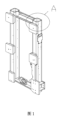
多段遠心圧縮機ZHに用いられる駆動モータは、取り付け様式B3、すなわち、略水平に取り付けられる。圧縮機要素及び駆動モータは、軸継手を介して直接結合される。モータは、4つの底脚を介してモータ支持体に結合される。現在、多段遠心圧縮機ZHに使用さるモータ支持体は、矩形である。図1及び2に示すように、モータ支持体の鋼材には主に正方形管が使用され、正方形管にはモータの4つの底脚に結合される4つのボスが溶接されている。ZH FS2圧縮機では、同じフレーム番号で駆動モータの軸高が5つあるのに対し、圧縮機要素サイズは1つしかない。従って、軸高が異なる駆動モータと高さの異なるモータ支持体を組み合わせて使用する必要がある。モータ軸高が高くなるほど、対応するモータ支持体に溶接されるボスの厚さは低くなる。市販の標準的な四角形管のサイズは一定である(180×180mm)。従って、モータブラケットの高さの調整範囲が制限される。高出力モータの場合、その軸は高くて大きいので、必要な支持高さは標準的な正方形管の辺の長さよりも低くなる。 The drive motor used in the multi-stage centrifugal compressor ZH has the mounting style B3, that is, it is mounted substantially horizontally. The compressor element and drive motor are directly coupled via a shaft coupling. The motor is coupled to the motor support via four bottom legs. The motor supports currently used in multi-stage centrifugal compressors ZH are rectangular. As shown in FIGS. 1 and 2, the steel material of the motor support mainly uses a square tube, and four bosses are welded to the square tube, which are coupled to the four bottom legs of the motor. The ZH FS2 compressor has only one compressor element size as opposed to five drive motor shaft heights for the same frame number. Therefore, it is necessary to use a combination of drive motors with different shaft heights and motor supports with different heights. The higher the motor shaft height, the lower the thickness of the boss welded to the corresponding motor support. A standard square tube on the market has a fixed size (180×180 mm). Therefore, the adjustable range of the height of the motor bracket is limited. For high power motors, the shaft is tall and large, so the required support height is less than the side length of a standard square tube.
従来技術におけるモータ支持構造は、通常、正方形管で作られているので、モータブラケットの高さの調整範囲が制限される。モータ支持構造体は、異なる軸高の複数のモータに適していない場合があり、普遍性が低いなどの技術的問題につながる。 Motor support structures in the prior art are usually made of square tubes, which limits the height adjustment range of the motor bracket. The motor support structure may not be suitable for multiple motors with different shaft heights, leading to technical problems such as low universality.
従って、本開示は、モータ支持装置及びモータ組立体を開発及び設計する。 Accordingly, the present disclosure develops and designs a motor support device and motor assembly.
本開示は、従来技術におけるモータ支持構造体が、通常、正方形管であるため、モータブラケットの高さの調整範囲が制限され、モータ支持構造体が、軸高が異なる複数のモータに適しておらず、普遍性が低い場合があるという技術課題の解決を目的とし、モータ支持装置及びモータ組立体を提供する。 Since the motor support structure in the prior art is usually a square tube, the height adjustment range of the motor bracket is limited, and the motor support structure is not suitable for multiple motors with different shaft heights. In order to solve the technical problem that the universality is sometimes low, a motor support device and a motor assembly are provided.
本開示によって提供されるモータ支持装置は、少なくとも1つのビーム構造体を含む。ビーム構造体は、金属プレートを曲げることによって形成される。金属プレートは、互いに相対する第1の長辺及び第2の長辺を含む。曲げることは、第1の長辺を第2の長辺に向かって曲げること、及び第2の長辺を第1の長辺に向かって曲げることを含む。曲げられた第1の長辺は、ビーム構造体の第1の自由端側面として形成される。曲げられた第2の長辺は、ビーム構造の第2の自由端側面として形成される。第1の自由端側面と第2の自由端側面との間には、ビーム構造体の断面が閉じない形状になるように間隔が存在する。 A motor support apparatus provided by the present disclosure includes at least one beam structure. A beam structure is formed by bending a metal plate. The metal plate includes a first long side and a second long side that are opposed to each other. Bending includes bending the first long side toward the second long side and bending the second long side toward the first long side. The bent first long side is formed as the first free end side of the beam structure. The bent second long side is formed as the second free end side of the beam structure. Between the first free end side and the second free end side there is a distance such that the cross-section of the beam structure has an open shape.
いくつかの実施形態では、ビーム構造体は、断面U字型のU字型ビームの構造形態である、及び/又は、ビーム構造体を曲げることによって、半閉鎖内部空洞構造が形成され、内部に支持板が設けられる。 In some embodiments, the beam structure is in the structural form of a U-beam with a U-shaped cross-section and/or bending the beam structure to form a semi-enclosed internal cavity structure in which A support plate is provided.
いくつかの実施形態では、互いに結合された複数のセクションを有する屈曲構造体が、そのビーム構造体の長さ方向に沿って形成される、又は、湾曲構造体が、そのビーム構造体の長さ方向に沿って形成される。 In some embodiments, a bending structure having multiple sections coupled together is formed along the length of the beam structure, or a bending structure is formed along the length of the beam structure. formed along the direction.
いくつかの実施形態では、結合された複数のセクションを有する屈曲構造体は、第1の直線セクション、第2の直線セクション、及び第3の直線セクションを含む。第2の直線セクションは、第1の直線セクション、第2の直線セクション、及び第3の直線セクションが順次結合されるように、第1の直線セクションと第3の直線セクションとの間に結合される。第1の直線セクションと第2の直線セクションは、その接合部で屈曲部を形成する。第2の直線セクションと第3の直線セクション(1c)は、その接合部で屈曲部を形成する。 In some embodiments, a bent structure having multiple sections joined includes a first straight section, a second straight section, and a third straight section. The second straight section is coupled between the first straight section and the third straight section such that the first straight section, the second straight section, and the third straight section are coupled sequentially. be. The first straight section and the second straight section form a bend at their junction. The second straight section and the third straight section (1c) form a bend at their junction.
いくつかの実施形態では、ビーム構造体は、第1のビーム及び第2のビームを含み、第1のビームの第2の直線セクションは、第2のビームの第2の直線セクションに結合され、第1のビームの第1の直線セクションは、第2のビームに対して離れて延び、第1のビームの第3の直線セクションも第2のビームに対して離れて延び、第2のビームの第1の直線セクションも第1のビームに対して離れて延び、第2のビームの第3の直線セクションも第1のビームに対して離れて延びている。 In some embodiments, the beam structure includes a first beam and a second beam, the second linear section of the first beam being coupled to the second linear section of the second beam; A first straight section of the first beam extends away from the second beam, a third straight section of the first beam also extends away from the second beam, and a third straight section of the first beam extends away from the second beam. A first straight section also extends away from the first beam and a third straight section of the second beam also extends away from the first beam.
いくつかの実施形態では、第1のビーム及び第2のビームは、同じ構造及び同じ形状を有し、それらは互いに対称的に結合され、及び/又は第1のビームの第2の直線セクションは、第2のビームの第2の直線セクションに永久的に結合される。 In some embodiments, the first beam and the second beam have the same structure and the same shape, they are symmetrically coupled to each other, and/or the second straight section of the first beam is , is permanently coupled to the second straight section of the second beam.
いくつかの実施形態では、第1の補強リブが、第1の直線セクション及び第2の直線セクションの接合部に設けられ、第1の補強リブの形状は、第1の直線セクション及び第2の直線セクションの接合部の屈曲部の形状に一致する、及び/又は、第2の補強リブが、第2の直線セクション及び第3の直線セクションの接合部に設けられ、第2の補強リブの形状は、第2の直線セクション及び第3の直線セクションの接合部の屈曲部の形状に一致する。 In some embodiments, a first reinforcing rib is provided at the junction of the first straight section and the second straight section, and the shape of the first reinforcing rib is the shape of the first straight section and the second straight section. conforming to the shape of the bend at the junction of the straight sections and/or a second stiffening rib is provided at the junction of the second straight section and the third straight section, the shape of the second stiffening rib corresponds to the shape of the bend at the junction of the second straight section and the third straight section.
いくつかの実施形態では、第1の補強リブは、ビーム構造体の閉じられていない形状の開口の側面に配置され、第1の自由端側面に永久的に結合された一端と、第2の自由端側面に永久的に結合された他端とを有する、及び/又は、第2の補強リブは、ビーム構造体の閉じられていない形状の開口の側面に配置され、第1の自由端側面に永久的に結合された一端と、第2の自由端側面に永久的に結合された他端とを有する。 In some embodiments, the first stiffening rib is positioned on the side of the open shaped opening of the beam structure, with one end permanently joined to the first free end side and the second stiffening rib. and/or the second stiffening rib is positioned on the side of the open profile opening of the beam structure and on the first free end side; and one end permanently connected to the second free end side.
本開示は、上記の実施形態のいずれか1つによるモータ支持装置と、モータとを含むモータ組立体をさらに提供する。モータ支持装置は、モータの底部に結合される。 The present disclosure further provides a motor assembly including a motor support device according to any one of the above embodiments and a motor. A motor support device is coupled to the bottom of the motor.
いくつかの実施形態では、モータ組立体は、モータベースプレートと、少なくとも1つの衝撃パッドとをさらに含む。モータベースプレートは、モータ支持装置の底部に取り付けられる。少なくとも1つの衝撃パッドは、モータベースプレートとモータ支持装置との間に設けられる。 In some embodiments, the motor assembly further includes a motor baseplate and at least one impact pad. A motor base plate is attached to the bottom of the motor support device. At least one impact pad is provided between the motor base plate and the motor support device.
本開示によって提供されるモータ支持装置及びモータ組立体は、以下の有益な効果を有する。 The motor support device and motor assembly provided by the present disclosure have the following beneficial effects.
本開示によれば、モータ支持装置は、少なくとも1つのビーム構造体として構成される。ビーム構造体は、矩形の金属プレートの2つの長辺を互いに向かって曲げることによって形成される構造体であり、曲げることによって形成される構造体は閉じていない。従って、本開示のビーム構造体では、異なるモータの軸方向高さに応じて曲げられる側面を調整することができる。従って、ビーム構造体の垂直高さを実際の要件に応じて調整することができ、モータ支持装置の高さの調整範囲が拡大され、駆動モータの異なる軸高の取り付け要件をよりよく満たし、モータ支持装置の普遍性が効果的に向上する。モータ支持装置は、異なる軸高を有する複数のモータに適している。 According to the present disclosure, the motor support device is configured as at least one beam structure. A beam structure is a structure formed by bending the two long sides of a rectangular metal plate towards each other, the structure formed by the bending being not closed. Therefore, in the beam structure of the present disclosure, the flexed sides can be adjusted for different axial heights of the motor. Therefore, the vertical height of the beam structure can be adjusted according to the actual requirements, the height adjustment range of the motor support device is expanded, and the installation requirements of different shaft heights of the drive motor are better met, and the motor The versatility of the supporting device is effectively improved. The motor support device is suitable for multiple motors with different shaft heights.
従来の直線ビームと比較して、背中合わせに互いに結合するように配置され、互いに反対方向に延びる2つの複数セクション屈曲ビーム構造体は、4つの異なる位置でモータに永久的に結合されるという条件を満たしながら、使用時のビーム構造体の数量を有効に低減し、材料を有効に低減し、コストを低減し、製品の経済性を改善し、機械全体のスペースを節約する。 Compared to conventional straight beams, two multi-section bent beam structures arranged back-to-back and extending in opposite directions to each other provided that they are permanently connected to the motor at four different positions. While satisfying, it effectively reduces the quantity of the beam structure in use, effectively reduces the material, reduces the cost, improves the economic efficiency of the product, and saves the space of the whole machine.
本開示の開放型のU字型支持体は、アフターサービス担当者のための組立、分解、操作及び処理を容易にするボルトによる組み立てを容易にし、設置及び維持のために好都合である。 The open U-shaped support of the present disclosure facilitates assembly with bolts that facilitates assembly, disassembly, operation and handling for after-sales service personnel, and is convenient for installation and maintenance.
図面は、必ずしも縮尺通りに描かれておらず、同じ参照数字は、異なる図の同様の構成要素を説明することができる。文字の添え字又は異なる文字の添え字を有する同じ参照数字は、類似の構成要素の異なる例を表す場合がある。図面は、限定ではなく例示的に一般的に様々な実施形態を示し、明細書及び特許請求の範囲と共に、開示された実施形態を説明するのに役立つ。適切な場合、同じ参照番号は、同一又は類似の要素を参照するために、図面全体にわたって使用される。当該実施形態は例示的であり、装置又は方法の網羅的又は排他的な実施形態であることを意図していない。 The drawings are not necessarily drawn to scale and like reference numerals may describe similar elements in different figures. The same reference numerals with letter suffixes or different letter suffixes may represent different instances of similar components. The drawings illustrate various embodiments generally by way of example and not by way of limitation, and together with the specification and claims serve to explain the disclosed embodiments. Where appropriate, the same reference numbers will be used throughout the drawings to refer to the same or analogous elements. The embodiments are illustrative and not intended to be exhaustive or exclusive embodiments of the apparatus or method.
当業者が本開示の技術的解決策をより良く理解できるように、本開示は、図面及び特定の実施構成を参照して以下に詳細に説明される。本開示の実施形態は、図面及び特定の実施形態を参照して以下にさらに詳細に説明されるが、本開示を限定するものとして解釈されるべきではない。 To enable those skilled in the art to better understand the technical solutions of the present disclosure, the present disclosure is described in detail below with reference to drawings and specific implementation configurations. Embodiments of the disclosure are described in further detail below with reference to the drawings and specific embodiments, which should not be construed as limiting the disclosure.
本開示で使用される「第1の」、「第2の」などの用語は、何らかの順序、数量、又は重要性を示すものではなく、単に異なる要素を区別するために使用される。また、「備える」、「含む」などの用語は、用語の前に記載された要素が用語の後ろに記載された要素をカバーすることを意味し、他の要素もカバーする可能性を排除するものではない。「上」、「下」、「左」、「右」などの用語は、相対的な位置関係を表すためにのみ使用される。記載された物体の絶対位置が変更される場合、それに応じて相対的な位置関係も変更される場合がある。 The terms "first," "second," etc. used in this disclosure do not imply any order, quantity, or importance, but are merely used to distinguish between different elements. Also, terms such as "comprising" and "including" mean that the element listed before the term covers the element listed after the term, and excludes the possibility of covering other elements as well. not a thing Terms such as "upper", "lower", "left", "right" are used only to describe relative positional relationships. If the absolute positions of the objects described are changed, the relative positions may be changed accordingly.
本開示において、第1の装置と第2の装置との間に特定の装置があると記載される場合、特定の装置と第1の装置又は第2の装置との間に介在する装置が存在する場合、又は介在しない場合がある。特定の装置が他の装置と結合されている記載される場合、特定の装置は、介在する装置を介さずに他の装置と直接結合する場合、又は介在する装置を介在させて他の装置と間接的に結合される場合がある。 In this disclosure, when it is stated that there is a specific device between a first device and a second device, there is a device intervening between the specific device and the first device or the second device. may or may not intervene. When a particular device is described as being coupled to another device, the particular device is either coupled directly to the other device without an intervening device, or to the other device through an intervening device. May be indirectly combined.
特に定義しない限り、本開示で使用される全ての用語(技術用語又は科学用語を含む)は、本開示の技術分野の当業者によって一般的に理解されるのと同じ意味を有する。また、一般的な辞書に定義されている用語は、関連する技術の文脈における意味と一致する意味を有すると解釈されるべきであり、本明細書で明示的にそのように定義されていない限り、理想化された意味又は極端に形式化された意味で解釈されるべきではないことを理解されたい。 Unless otherwise defined, all terms (including technical or scientific terms) used in this disclosure have the same meaning as commonly understood by one of ordinary skill in the art of this disclosure. Also, terms defined in common dictionaries are to be construed to have a meaning consistent with their meaning in the context of the relevant art, unless explicitly defined as such herein. , should not be interpreted in an idealized or overly formalized sense.
当業者に知られている技術、方法、及び装置は、詳細に論じられない場合もあるが、適切な場合には、その技術、方法、及び装置は、本明細書の一部として考慮されるべきである。 Techniques, methods, and apparatus known to those skilled in the art may not be discussed in detail, but where appropriate, such techniques, methods, and apparatus are considered part of this specification. should.
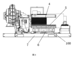
図3及び4に示されるように、本開示は、モータ支持装置を提供する。モータ支持装置100は、少なくとも1つのビーム構造体1を含む。ビーム構造体1は、金属プレートを曲げることによって形成される。金属プレートは、互いに相対する第1の長辺及び第2の長辺を含む。曲げることは、第1の長辺を第2の長辺に向かって曲げること及び第2の長辺を第1の長辺に向かって曲げることを含む。曲げられた第1の長辺は、ビーム構造体1の第1の自由端側面11として形成され、曲げられた第2の長辺は、ビーム構造体1の第2の自由端側面12として形成され、第1の自由端側面11と第2の自由端側面12の間には、ビーム構造体1の横断面が閉じない形状となるように、間隔が存在する。
As shown in FIGS. 3 and 4, the present disclosure provides a motor support device.
本開示によれば、モータ支持装置は、少なくとも1つのビーム構造体として構成される。ビーム構造体は、矩形の金属プレートの2つの長辺を相対的に曲げることによって形成される構造体であり、曲げることによって形成される構造体は閉じられていない。従って、本開示のビーム構造体によれば、曲げられた縁部は、様々なモータ軸方向高さに応じて調整することができる。従って、ビーム構造体の垂直高さは、実際の要件に応じて調整することができ、モータ支持装置の高さの調整範囲が拡大され、異なる軸高の駆動モータの取り付け要件をよりよく満たし、モータ支持装置の普遍性を効果的に向上させることができる。このモータ支持装置は、異なる軸高を有する複数のモータに好適である。 According to the present disclosure, the motor support device is configured as at least one beam structure. A beam structure is a structure formed by bending two long sides of a rectangular metal plate relative to each other, and the structure formed by the bending is not closed. Therefore, according to the beam structure of the present disclosure, the bent edge can be adjusted for different motor axial heights. Therefore, the vertical height of the beam structure can be adjusted according to the actual requirements, the height adjustment range of the motor support device is expanded, and the installation requirements of the drive motors with different shaft heights are better met, The versatility of the motor support device can be effectively improved. This motor support device is suitable for multiple motors with different shaft heights.
ビーム構造体1は、ビーム断面がU字型の構造形態のU字型ビームである、及び/又は、ビーム構造体1は、曲げることで半閉鎖型の内部空洞構造体15として形成されており、支持板2が内部空洞構造体15に設けられている。これは、本開示のビーム構造体の好ましい構造形態である。ビーム構造体を断面U字型のU字型ビームとして構成することで、軸高が異なるモータを満足させるために、閉じられていない間隔の側面によってビーム構造体の垂直高さの大きさをさらに調整することができ、さらに、ビーム構造体の内部空洞に支持板を配置した構造形態に設定することで、ビーム構造体の支持強度をさらに向上させることができる。
The
互いに結合された複数のセクションを有する屈曲構造体は、そのビーム構造体1の長さ方向に沿って形成される、又は湾曲構造体は、そのビーム構造体1の長さ方向に沿って形成される。本開示では、ビーム構造体の長さ方向における好ましい構造形態として2つの異なる構造形態が存在する。第1の好ましい構造形態は、複数のセクションが互いに結合された屈曲構造体である。このような屈曲構造体は、両端で個別にモータへの直線セクションの締結接続部を形成するのに有利であるが、中間セクションは、ベースプレート又はシャーシなどのモータ支持装置の底部に結合される。従って、1つのビーム構造体の特別な構成によれば、異なる構成要素への結合は、ビームの異なる部分で実現することができ、これは、固定作用を実現しながら、材料を削減し、よりコンパクトな構造体を提供することができる。同様に、湾曲構造のビーム構造体は、ビーム構造体の端部とモータとの間に締結接続部を形成することができるが、中間セクションは、ベースプレート又はシャーシなどのモータ支持装置の底部に結合される。従って、1つのビーム構造体の特別な構成によれば、異なる構成要素への結合は、ビームの異なる部分で実現することができ、これは、固定作用を実現しながら、材料を削減し、よりコンパクトな構造を提供することができる。
A bending structure having multiple sections coupled together is formed along the length of the
互いに結合された複数のセクションを有する屈曲構造体1は、第1の直線セクション1a、第2の直線セクション1b、及び第3の直線セクション1cを含む。第2の直線セクション1bは、第1の直線セクション1a、第2の直線セクション1b、及び第3の直線セクション1cが順次結合されるように、第1の直線セクション1aと第3の直線セクション1cとの間に結合される。第1の直線セクション1a及び第2の直線セクション1bは、その接合部で屈曲部を形成する。第2の直線セクション1b及び第3の直線セクション1cは、その接合部で屈曲部を形成する。これは、本開示の複数のセクションを有する屈曲構造体のビーム構造体のさらに好ましい構造形態であり、すなわち、第1の直線セクション及び第3の直線セクションによってモータとの締結接続部を形成し、第2の直線セクションによってモータ支持装置とベースプレート又はシャーシとの締結接続部を形成することができる。
A
ビーム構造体1は、第1のビーム13及び第2のビーム14を含む。第1のビーム13の第2の直線セクションは、第2のビーム14の第2の直線セクションに結合される。第1のビーム13の第1のセクションは、第2のビーム14に対して離れて延び、第1のビーム13の第3のセクションは、第2のビーム14に対して離れて延びる。第2のビーム14の第1のセクションは、第1のビーム13に対して離れて延び、第2のビーム14の第3のセクションは、第1のビーム13に対して離れて延びる。すなわち、「X」字型のモータ支持体が形成される。従来の直線ビームと比較して、背中合わせに配置され、互いに接続され、互いに対して離れて延びる2つの複数セクション屈曲ビーム構造体は、4つの異なる位置でモータに永久的に結合されるという条件を満たしながら、使用時のビーム構造体の数量を有効に低減し、材料を有効に低減し、コストを低減し、製品の経済効率を高め、機械全体のスペースを節約する。
本開示のX字型モータ支持体は、単段遠心送風機に優先的に適用される。圧縮機要素のサイズは1つだけであるが、駆動モータの軸高は全部で5つある。モータの取り付け様式は、4つの底脚及びフランジを用いる取り付け様式である。同じ取り付けサイズのモータに関して、X字型モータ支持体が必要とする材料は矩形支持体よりも少なく、これはコストを低減し、製品の経済性を向上させ、機械全体のスペースを節約する。 The X-shaped motor support of the present disclosure is preferentially applied to single-stage centrifugal fans. Although there is only one size of compressor element, there are a total of five drive motor shaft heights. The mounting style of the motor is a mounting style with four bottom legs and a flange. For the same mounting size motor, the X-shaped motor support requires less material than the rectangular support, which reduces cost, improves product economics, and saves space in the overall machine.
第1のビーム13及び第2のビーム14は同じ構造及び同じ形状を有し、それらは互いに対称に結合され、及び/又は第1のビーム13の第2の直線セクションは第2のビーム14の第2の直線セクションに永久的に結合される。好ましくは、結合には、ねじ、溶着、又は接着などが用いられる。本開示の第1のビーム及び第2のビームの構造形態、すなわち、第1のビーム及び第2のビームの構造及び形状は、同一に設定されることがさらに好ましく、これは、モータの傾きを防止するために、モータを4方向から均一に支持することを可能にする。第1のビーム及び第2のビームの2つの直線セクションを固定結合することは、第1のビーム及び第2のビームを中間セクションによって一体的に固定することを可能にし、モータ支持装置の安定性が向上する。これは、モータの底部に配置される場合に効果的で安定した支持を提供する。
The
第1の補強リブ31は、第1の直線セクション1aと第2の直線セクション1bの接合部に設けられ、第1の補強リブ31の形状は、第1の直線セクション1aと第2の直線セクション1bの接合部の屈曲部の形状に一致する、及び/又は、第2の補強リブ32は、第2の直線セクション1bと第3の直線セクション1cの接合部に設けられ、第2の補強リブ32の形状は、第2の直線セクション1bと第3の直線セクション1cの接合部の屈曲部の形状に一致する。第1の補強リブを設けることにより、第1の直線セクションと第2の直線セクションの接合部において補強及び強化効果を得ることができ、これはモータ支持装置の構造強度をさらに効果的に向上させることができる。第2の補強リブを設けることにより、第2の直線セクションと第3の直線セクションの接合部において補強及び強化効果が得られ、これは、モータ支持装置の構造強度をさらに効果的に向上させることができる。
A first reinforcing
第1の補強リブ31は、ビーム構造体1の閉じられていない形状の開口の側面に配置され、第1の自由端側面11に永久的に結合された一端と第2の自由端側面12に永久的に結合された他端とを有し、及び/又は、第2の補強リブ32は、ビーム構造体1の閉じられていない形状の開口の側面に配置され、第1の自由端側面11に永久的に結合された一端と第2の自由端側面12に永久的に結合された他端とを有する。ビーム構造体は、片側に閉じていない形状の開口を定めるので、その位置の構造強度に深刻なリスクがあり、圧力下で変形又は損傷などの現象が発生する可能性がある。従って、開口位置に配置された第1の補強リブで上端側面と下端側面を結合及び締結することで、開口及び屈曲部の構造強度を効果的に向上させることができる。開口位置に配置された第2の補強リブで上端側面と下端側面とを結合及び締結することで、開口及び屈曲部の構造強度を効果的に向上させることもできる。
A
図5に示すように、本開示は、上記実施形態のいずれか1つによるモータ支持装置100を含み、さらにモータ4を含むモータ組立体をさらに提供する。モータ支持装置100は、モータ4の底面に結合される。
As shown in FIG. 5 , the present disclosure further provides a motor assembly that includes a
本開示のX字型モータ支持体は、単段遠心送風機において優先的に適用される。製品の圧縮機要素のサイズは1つだけであり、使用される駆動モータの軸高は全部で5つである。モータの取り付け様式は、4つの底脚及びフランジを有する取り付け様式である。本開示のX字型モータ支持体のブラケットは、2つの主たるU字型ビームによって構成される。各U字型ビームは、金属プレートに簡単な曲げ加工を施すことで製造される。いくつかの補強リブ/支持プレートは、モータのための支持構造体の強度及び剛性を保証するためにU字型ビーム上に溶着される。U字型ビームの高さ調整範囲が広いので、軸高が異なる駆動モータの取り付け要件をより簡単に満たすことができる。同じ取り付けサイズのモータに対して、X字型モータ支持体が必要とする材料は、矩形支持体よりも少なく、これは、コストを低減し、製品の経済性を向上させ、機械全体のスペースを節約する。 The X-shaped motor support of the present disclosure is preferentially applied in single-stage centrifugal fans. There is only one size of compressor element in the product, and a total of five drive motor shaft heights are used. The mounting style of the motor is a mounting style with four bottom legs and a flange. The X-shaped motor support bracket of the present disclosure is constructed by two main U-shaped beams. Each U-shaped beam is manufactured by simple bending of a metal plate. Several reinforcing ribs/support plates are welded onto the U-beams to ensure the strength and rigidity of the support structure for the motor. The wide height adjustment range of the U-shaped beam makes it easier to meet the mounting requirements of drive motors with different shaft heights. For the same mounting size motor, the X-shaped motor support requires less material than the rectangular support, which reduces costs, improves product economics, and saves space in the overall machine. save.
本開示のX字型モータ支持体において、ブラケットは、2つの主たるU字型ビームで構成される。各U字型ビームは、金属プレートに簡単な曲げ加工を施すことで製造される。加えて、いくつかの補強リブ/支持プレートは、モータのための支持構造の強度及び剛性を保証するためにU字型ビーム上に溶着される。 In the disclosed X-shaped motor support, the bracket consists of two main U-shaped beams. Each U-shaped beam is manufactured by simple bending of a metal plate. Additionally, some reinforcing ribs/support plates are welded onto the U-beams to ensure the strength and rigidity of the support structure for the motor.
本開示の利点は、以下の通りである。 Advantages of the present disclosure are as follows.
1)U字型ビームの製造プロセスにより、X字型支持体の高さの調整範囲が大きく、これは、異なる軸高の駆動モータの取り付け要件をより良く満たすことができる。2)同じサイズのモータを取り付ける場合、X字型モータ支持体が必要とする材料は、矩形支持体よりも少なく、これは、製品の経済性を向上させ、機械全体のスペースを節約する。3)保守及び取り付けの利便性:開いたU字型支持体はボルトでの組み立てを容易にするので、アフターサービス担当者の組立、分解、操作、及び処理が容易となる。 1) Due to the manufacturing process of U-shaped beam, the height adjustment range of X-shaped support is large, which can better meet the installation requirements of drive motors with different shaft heights. 2) For mounting the same size motor, the X-shaped motor support requires less material than the rectangular support, which improves the economics of the product and saves the space of the whole machine. 3) Convenience of maintenance and installation: The open U-shaped support facilitates bolt assembly, thus facilitating assembly, disassembly, operation and disposal by after-sales service personnel.
さらに、モータベースプレート5及び衝撃パッド6を備える。モータベースプレート5は、モータ支持装置100の底部に取り付けられる。少なくとも1つの衝撃パッド6は、モータベースプレート5とモータ支持器具100との間に設けられる。衝撃パッドは、モータの衝撃吸収を行うことができる。
Furthermore, it comprises a
加えて、本明細書では例示的な実施形態が説明されているが、その範囲は、本開示に基づく等価な要素、修正例、除外例、組み合わせ(例えば、種々の実施形態をまたぐ方式)、適応例又は変更例を含む何らかの及び全ての実施形態を含む。請求項に記載された要素は、請求項に採用された言語で広く説明されるべきであり、本明細書に記載された又は本開示の実現時の実施例に限定されず、その実施例は非限定的に説明される。従って、本明細書及び実施例は、例としてのみ考慮されることが意図される。真の範囲及び思想は、以下の請求項及びその均等物の全範囲によって示される。 In addition, although exemplary embodiments are described herein, their scope does not cover equivalent elements, modifications, exclusions, combinations (e.g., ways across the various embodiments), Includes any and all embodiments including adaptations or modifications. Claimed elements should be set forth broadly in the language employed in the claims and not limited to the implementations described herein or in the implementation of the disclosure, which implementations may include: Non-limiting description. It is therefore intended that the specification and examples be considered as exemplary only. The true scope and spirit are indicated by the following claims and their full scope of equivalents.
上記の説明は、例示的であることが意図されるが制限的ではない。例えば、上記の実施例(又はその1又は2以上の方式)は、互いに組み合わせて使用することができる。他の実施形態は、上記の説明を読むことで当業者が使用することができる。加えて、上記の具体的な実施形態において、本開示を簡略化するために、様々な特徴は、まとめて記載する場合がある。このことは、請求項に記載されていない開示された特徴が、いずれかの請求項に必要であるという意図として説明されるべきではない。それどころか、本開示の主題は、特定の開示された実施形態の全ての特徴よりも少ない特徴によって定義される場合がある。従って、以下の請求項は、本明細書で実施例又は実施形態として特定の実施構成に組み込まれており、ここでは各請求項は別個の実施形態として独立している。これらの実施形態は、様々な組み合わせ又は順列で互いに組み合わせ得ることが企図される。本開示の範囲は、添付の請求項及びその均等物の全範囲を参照して決定されるべきである。 The descriptions above are intended to be illustrative, not limiting. For example, the above embodiments (or one or more modalities thereof) can be used in combination with each other. Other embodiments can be used by those of ordinary skill in the art upon reading the above description. Additionally, in the specific embodiments described above, various features may be grouped together to simplify the disclosure. This should not be interpreted as an intention that an unclaimed disclosed feature is required in any claim. Rather, subject matter of this disclosure may be defined by less than all features of a particular disclosed embodiment. Thus, the following claims are hereby incorporated into certain implementations as examples or embodiments, with each claim standing on its own as a separate embodiment. It is contemplated that these embodiments may be combined with each other in various combinations or permutations. The scope of the disclosure should be determined with reference to the appended claims along with their full scope of equivalents.
上記の実施形態は、本開示の単なる例示的な実施形態であり、本開示を限定することを意図していない。本開示の保護範囲は、請求項によって定義される。本開示の本質及び保護範囲内で、当業者によって本開示に様々な修正又は等価な置換を行うことができ、そのような修正又は等価な置換は本開示の保護範囲に属するとみなされるべきである。 The above embodiments are merely exemplary embodiments of the present disclosure and are not intended to limit the present disclosure. The protection scope of the disclosure is defined by the claims. Various modifications or equivalent replacements can be made to the present disclosure by persons skilled in the art within the essence and protection scope of the present disclosure, and such modifications or equivalent replacements should be regarded as belonging to the protection scope of the present disclosure. be.
Claims (10)
前記金属プレートは、互いに相対する第1の長辺及び第2の長辺を含み、
前記曲げることは、前記第1の長辺を前記第2の長辺に向かって曲げること及び前記第2の長辺を前記第1の長辺に向かって曲げることを含み、
前記曲げられた第1の長辺は、曲げられた後の前記ビーム構造体(1)の第1の自由端側面(11)として形成され、
前記曲げられた第2の長辺は、曲げられた後の前記ビーム構造体(1)の第2の自由端側面(12)として形成され、
前記第1の自由端側面(11)と前記第2の自由端側面(12)との間には、前記ビーム構造体(1)の断面が閉じない形状になるように間隔が存在する、モータ支持装置。 A motor support device comprising at least one beam structure (1) formed by bending a metal plate,
the metal plate includes a first long side and a second long side facing each other;
The bending includes bending the first long side toward the second long side and bending the second long side toward the first long side;
said bent first long side is formed as a first free end side (11) of said beam structure (1) after bending,
said bent second long side is formed as a second free end side (12) of said beam structure (1) after bending,
Between said first free end side (11) and said second free end side (12) there is a gap such that the cross section of said beam structure (1) is not closed. support device.
前記第2の直線セクション(1b)は、前記第1の直線セクション(1a)、前記第2の直線セクション(1b)、及び前記第3の直線セクション(1c)が順次結合されるように、前記第1の直線セクション(1a)と前記第3の直線セクション(1c)との間に結合され、
前記第1の直線セクション(1a)と前記第2の直線セクション(1b)は、接合部で屈曲部を形成し、
前記第2の直線セクション(1b)と前記第3の直線セクション(1c)は、接合部で屈曲部を形成する、請求項3に記載のモータ支持装置。 said bent structure having a plurality of sections coupled together comprises a first straight section (1a), a second straight section (1b) and a third straight section (1c);
Said second straight section (1b) comprises said coupled between a first straight section (1a) and said third straight section (1c);
said first straight section (1a) and said second straight section (1b) form a bend at the junction,
4. Motor support device according to claim 3, wherein said second straight section (1b) and said third straight section (1c) form a bend at a junction.
前記第1のビーム(13)の第2の直線セクションは、前記第2のビーム(14)の第2の直線セクションに結合され、
前記第1のビーム(13)の第1の直線セクションは、前記第2のビーム(14)に対して離れて延び、前記第1のビーム(13)の第3の直線セクションは、前記第2のビーム(14)に対して離れて延びており、
前記第2のビーム(14)の第1の直線セクションは、前記第1のビーム(13)に対して離れて延び、前記第2のビーム(14)の第3の直線セクションは、前記第1のビーム(13)に対して離れて延びている、請求項4に記載のモータ支持装置。 said at least one beam structure (1) comprising a first beam (13) and a second beam (14);
a second straight section of said first beam (13) is coupled to a second straight section of said second beam (14);
A first straight section of said first beam (13) extends away from said second beam (14) and a third straight section of said first beam (13) extends away from said second beam (14). extends away from the beam (14) of
A first straight section of said second beam (14) extends away from said first beam (13) and a third straight section of said second beam (14) extends from said first beam (13). 5. A motor support device according to claim 4, extending away from the beam (13) of the .
第2の補強リブ(32)が、前記第2の直線セクション(1b)及び前記第3の直線セクション(1c)の前記接合部に設けられ、前記第2の補強リブ(32)の形状は、前記第2の直線セクション(1b)及び前記第3の直線セクション(1c)の前記接合部の屈曲部の形状に一致する、請求項4に記載のモータ支持装置。 A first reinforcing rib (31) is provided at the junction of the first straight section (1a) and the second straight section (1b), the shape of the first reinforcing rib (31) being: conforming to the shape of the bend at the junction of the first straight section (1a) and the second straight section (1b); and/or
A second reinforcing rib (32) is provided at the junction of the second straight section (1b) and the third straight section (1c), the shape of the second reinforcing rib (32) being: 5. Motor support device according to claim 4, conforming to the shape of the bends of the joints of the second straight section (1b) and the third straight section (1c).
前記第2の補強リブ(32)は、前記ビーム構造体(1)の閉じられていない形状の開口の側面に配置され、前記第1の自由端側面(11)に永久的に結合された一端と、前記第2の自由端側面(12)に永久的に結合された他端とを有する、請求項7に記載のモータ支持装置。 Said first stiffening rib (31) is arranged on the side of the open profile opening of said beam structure (1) and at one end permanently joined to said first free end side (11). and the other end permanently connected to said second free end side (12); and/or
Said second stiffening rib (32) is arranged on the side of the open profile opening of said beam structure (1) and at one end permanently joined to said first free end side (11). and a second end permanently connected to said second free end side (12).
請求項1から8のいずれかに記載のモータ支持装置(100)と、
モータ(4)と、
を備え、前記モータ支持装置(100)は、前記モータ(4)の底部に結合されている、モータ組立体。 A motor assembly,
a motor support device (100) according to any one of claims 1 to 8;
a motor (4);
wherein said motor support device (100) is coupled to the bottom of said motor (4).
前記モータベースプレート(5)と前記モータ支持装置(100)との間に設けられた少なくとも1つの衝撃パッド(6)と、
をさらに備える、請求項9に記載のモータ組立体。 a motor base plate (5) attached to the bottom of the motor support device (100);
at least one impact pad (6) provided between the motor base plate (5) and the motor support device (100);
10. The motor assembly of claim 9, further comprising:
Applications Claiming Priority (3)
| Application Number | Priority Date | Filing Date | Title |
|---|---|---|---|
| CN202021077519.7 | 2020-06-11 | ||
| CN202021077519.7U CN211958956U (en) | 2020-06-11 | 2020-06-11 | Motor supporting device and motor assembly |
| PCT/CN2021/099583 WO2021249524A1 (en) | 2020-06-11 | 2021-06-11 | Electric motor supporting device and electric motor assembly |
Publications (1)
| Publication Number | Publication Date |
|---|---|
| JP2023528979A true JP2023528979A (en) | 2023-07-06 |
Family
ID=73159305
Family Applications (1)
| Application Number | Title | Priority Date | Filing Date |
|---|---|---|---|
| JP2022576066A Pending JP2023528979A (en) | 2020-06-11 | 2021-06-11 | Electric motor support device and electric motor assembly |
Country Status (6)
| Country | Link |
|---|---|
| EP (1) | EP4167445A1 (en) |
| JP (1) | JP2023528979A (en) |
| KR (1) | KR20230019963A (en) |
| CN (1) | CN211958956U (en) |
| BR (1) | BR112022024945A2 (en) |
| WO (1) | WO2021249524A1 (en) |
Families Citing this family (1)
| Publication number | Priority date | Publication date | Assignee | Title |
|---|---|---|---|---|
| CN211958956U (en) * | 2020-06-11 | 2020-11-17 | 阿特拉斯·科普柯(无锡)压缩机有限公司 | Motor supporting device and motor assembly |
Family Cites Families (7)
| Publication number | Priority date | Publication date | Assignee | Title |
|---|---|---|---|---|
| US5561902A (en) | 1994-09-28 | 1996-10-08 | Cosma International Inc. | Method of manufacturing a ladder frame assembly for a motor vehicle |
| US5752688A (en) * | 1996-09-10 | 1998-05-19 | Emerson Electric Co. | Support assembly that is selectively repositionable and attachable to different sides of an air cooled machine housing |
| CN202630327U (en) * | 2012-06-27 | 2012-12-26 | 珠海格力电器股份有限公司 | Motor limiting device |
| JP2018165491A (en) * | 2017-03-28 | 2018-10-25 | 株式会社荏原製作所 | Horizontal shaft pump and basis for horizontal shaft pump |
| CN210718024U (en) * | 2019-09-18 | 2020-06-09 | 浙江国祥股份有限公司 | Fan motor assembly |
| CN210490638U (en) * | 2019-10-12 | 2020-05-08 | 佛山市源绿品通风设备有限公司 | Longitudinal adjusting and fixing mechanism of motor base |
| CN211958956U (en) * | 2020-06-11 | 2020-11-17 | 阿特拉斯·科普柯(无锡)压缩机有限公司 | Motor supporting device and motor assembly |
-
2020
- 2020-06-11 CN CN202021077519.7U patent/CN211958956U/en active Active
-
2021
- 2021-06-11 KR KR1020237000431A patent/KR20230019963A/en unknown
- 2021-06-11 WO PCT/CN2021/099583 patent/WO2021249524A1/en unknown
- 2021-06-11 EP EP21822768.4A patent/EP4167445A1/en active Pending
- 2021-06-11 BR BR112022024945A patent/BR112022024945A2/en unknown
- 2021-06-11 JP JP2022576066A patent/JP2023528979A/en active Pending
Also Published As
| Publication number | Publication date |
|---|---|
| WO2021249524A1 (en) | 2021-12-16 |
| EP4167445A1 (en) | 2023-04-19 |
| KR20230019963A (en) | 2023-02-09 |
| BR112022024945A2 (en) | 2022-12-27 |
| CN211958956U (en) | 2020-11-17 |
Similar Documents
| Publication | Publication Date | Title |
|---|---|---|
| JP2023528979A (en) | Electric motor support device and electric motor assembly | |
| EP2787290B1 (en) | Casing for outdoor unit for air conditioning device | |
| JP2017215079A (en) | Outdoor unit for air conditioner | |
| CN215467194U (en) | Rotation center assembly for straightening machine | |
| CN211622612U (en) | Arc corner building system | |
| CN212172367U (en) | Engine upper cover support for loader | |
| CN215870569U (en) | Install type security protection crane span structure fast | |
| CN205402945U (en) | Machine in quick -witted split type braced frame and air conditioning in air conditioning | |
| CN210601944U (en) | Fan wall and air conditioning unit | |
| CN217076794U (en) | Tower crane capable of being assembled | |
| KR102536033B1 (en) | Duct assembly | |
| CN220087744U (en) | Supporting beam, frame structure thereof and control cabinet | |
| CN219287925U (en) | Bearing cabinet base structure | |
| CN214089588U (en) | Gate with modularized frame | |
| CN216842276U (en) | Axial flow fan with adjustable center height | |
| CN215951594U (en) | Outer quick-witted protection casing of air conditioner convenient to dismouting | |
| CN219360029U (en) | Curb plate vulcanizer that bearing capacity is strong | |
| CN216830897U (en) | Robot shell structure and robot | |
| CN212204792U (en) | Air outlet mesh enclosure and air conditioner outdoor unit | |
| CN214274056U (en) | A installing support for fan | |
| CN220233914U (en) | Power distribution cabinet protection device | |
| CN216319154U (en) | Liver disease ascites aspirator of infectious department | |
| CN210714098U (en) | Construction enclosure | |
| CN213742717U (en) | Stadium fence | |
| CN219225412U (en) | Computer cabinet with good heat dissipation effect |
Legal Events
| Date | Code | Title | Description |
|---|---|---|---|
| A521 | Request for written amendment filed |
Free format text: JAPANESE INTERMEDIATE CODE: A523 Effective date: 20221208 |
|
| A621 | Written request for application examination |
Free format text: JAPANESE INTERMEDIATE CODE: A621 Effective date: 20221208 |
|
| A977 | Report on retrieval |
Free format text: JAPANESE INTERMEDIATE CODE: A971007 Effective date: 20231109 |
|
| A131 | Notification of reasons for refusal |
Free format text: JAPANESE INTERMEDIATE CODE: A131 Effective date: 20231130 |
|
| A601 | Written request for extension of time |
Free format text: JAPANESE INTERMEDIATE CODE: A601 Effective date: 20240229 |
|
| A521 | Request for written amendment filed |
Free format text: JAPANESE INTERMEDIATE CODE: A523 Effective date: 20240424 |