JP2023521950A - Sanitary module kit, sanitary functional assembly, method of manufacturing sanitary functional assembly - Google Patents
Sanitary module kit, sanitary functional assembly, method of manufacturing sanitary functional assembly Download PDFInfo
- Publication number
- JP2023521950A JP2023521950A JP2022555671A JP2022555671A JP2023521950A JP 2023521950 A JP2023521950 A JP 2023521950A JP 2022555671 A JP2022555671 A JP 2022555671A JP 2022555671 A JP2022555671 A JP 2022555671A JP 2023521950 A JP2023521950 A JP 2023521950A
- Authority
- JP
- Japan
- Prior art keywords
- outflow
- sanitary
- elements
- control
- module kit
- Prior art date
- Legal status (The legal status is an assumption and is not a legal conclusion. Google has not performed a legal analysis and makes no representation as to the accuracy of the status listed.)
- Pending
Links
Images


Classifications
-
- E—FIXED CONSTRUCTIONS
- E03—WATER SUPPLY; SEWERAGE
- E03C—DOMESTIC PLUMBING INSTALLATIONS FOR FRESH WATER OR WASTE WATER; SINKS
- E03C1/00—Domestic plumbing installations for fresh water or waste water; Sinks
- E03C1/02—Plumbing installations for fresh water
- E03C1/04—Water-basin installations specially adapted to wash-basins or baths
- E03C1/0403—Connecting the supply lines to the tap body
-
- E—FIXED CONSTRUCTIONS
- E03—WATER SUPPLY; SEWERAGE
- E03C—DOMESTIC PLUMBING INSTALLATIONS FOR FRESH WATER OR WASTE WATER; SINKS
- E03C1/00—Domestic plumbing installations for fresh water or waste water; Sinks
- E03C1/02—Plumbing installations for fresh water
- E03C1/021—Devices for positioning or connecting of water supply lines
- E03C1/023—Devices for positioning or connecting of water supply lines with flow distribution, e.g. diverters
-
- E—FIXED CONSTRUCTIONS
- E03—WATER SUPPLY; SEWERAGE
- E03C—DOMESTIC PLUMBING INSTALLATIONS FOR FRESH WATER OR WASTE WATER; SINKS
- E03C1/00—Domestic plumbing installations for fresh water or waste water; Sinks
- E03C1/02—Plumbing installations for fresh water
- E03C1/04—Water-basin installations specially adapted to wash-basins or baths
- E03C1/0404—Constructional or functional features of the spout
- E03C1/0405—Constructional or functional features of the spout enabling multiple spray patterns
-
- E—FIXED CONSTRUCTIONS
- E03—WATER SUPPLY; SEWERAGE
- E03C—DOMESTIC PLUMBING INSTALLATIONS FOR FRESH WATER OR WASTE WATER; SINKS
- E03C2201/00—Details, devices or methods not otherwise provided for
- E03C2201/30—Diverter valves in faucets or taps
-
- E—FIXED CONSTRUCTIONS
- E03—WATER SUPPLY; SEWERAGE
- E03C—DOMESTIC PLUMBING INSTALLATIONS FOR FRESH WATER OR WASTE WATER; SINKS
- E03C2201/00—Details, devices or methods not otherwise provided for
- E03C2201/40—Arrangement of water treatment devices in domestic plumbing installations
Landscapes
- Health & Medical Sciences (AREA)
- Life Sciences & Earth Sciences (AREA)
- Engineering & Computer Science (AREA)
- Hydrology & Water Resources (AREA)
- Public Health (AREA)
- Water Supply & Treatment (AREA)
- Devices For Dispensing Beverages (AREA)
- Domestic Plumbing Installations (AREA)
- Orthopedics, Nursing, And Contraception (AREA)
- Absorbent Articles And Supports Therefor (AREA)
Abstract

本発明は、少なくとも1つの流出エレメント(2)と、少なくとも1つの制御エレメント(3)と、流出エレメント(2)を制御エレメント(3)に流体接続することができる少なくとも1つの結合エレメント(4)と、を備えた衛生モジュールキット(1)に関し、機能的に異なる少なくとも2つの制御エレメント(3)が含まれており、これらの制御エレメントは、個別にまたは一緒に流出エレメント(2)に選択的に流体接続可能である。
The present invention comprises at least one outflow element (2), at least one control element (3) and at least one coupling element (4) capable of fluidly connecting the outflow element (2) to the control element (3). contains at least two functionally different control elements (3), which control elements individually or together are selectively directed to the outflow element (2) is fluidly connectable to
Description
本発明は、少なくとも1つの流出エレメントと、少なくとも1つの制御エレメントと、流出エレメントを制御エレメントに流体接続することができる少なくとも1つの結合エレメントと、を備えた衛生モジュールキットに関する。 The present invention relates to a sanitary module kit comprising at least one outflow element, at least one control element and at least one coupling element with which the outflow element can be fluidly connected to the control element.
本発明はさらに、少なくとも1つの流出エレメントと、少なくとも1つの制御エレメントと、流出エレメントを制御エレメントに流体接続することができる少なくとも1つの結合エレメントと、を備えた衛生機能アセンブリに関する。 The invention further relates to a sanitary function assembly comprising at least one outflow element, at least one control element and at least one coupling element with which the outflow element can be fluidly connected to the control element.
さらに、本発明は、衛生機能アセンブリを製造する方法に関する。 Furthermore, the invention relates to a method of manufacturing a sanitary functional assembly.
衛生機能アセンブリは、様々な場所で、様々な衛生設備のために必要とされる。しかし、設置状況が通常の基準から外れており個別の解決策を講じる必要がある場合、既知の入手可能な製品によってこの個別の解決策を講じることは、極めて困難であることが多い。 Sanitary functional assemblies are required at different locations and for different sanitary installations. However, if the installation situation deviates from normal standards and requires a custom solution, it is often very difficult to do so with known available products.
たとえば、家具または衛生物体に組み込まれるべき衛生機能アセンブリの設置時に、既知の解決策が適していないことは何度も生じている。なぜならば、既知の解決策は、特定の場所または設置状況によって規定された制限に柔軟に適合することができないからである。特に、特注製作品として構成された家具に衛生機能アセンブリを備えるべき場合、家具に衛生機能アセンブリを個別化された簡単な方法で備えることができるために適した解決策はない。 For example, it often happens that the known solutions are not suitable when installing sanitary functional assemblies to be incorporated into furniture or sanitary objects. This is because known solutions cannot flexibly adapt to the limitations imposed by a particular location or installation situation. Especially if a piece of furniture constructed as a custom piece is to be equipped with a hygiene function assembly, there is no suitable solution because the furniture can be equipped with the hygiene function assembly in an individualized and simple manner.
したがって、本発明の根底にある課題は、衛生機能アセンブリをより簡単かつフレキシブルに形成することができる技術的な解決手段を提供することである。 The problem underlying the present invention is therefore to provide a technical solution with which a sanitary function assembly can be constructed more simply and flexibly.
この課題の解決手段は、本発明によれば、それぞれの独立請求項によって提供される。 The solution to this problem is provided according to the invention by the respective independent claims.
特に、本発明によれば、課題を解決するために、少なくとも1つの流出エレメントと、少なくとも1つの制御エレメントと、流出エレメントを制御エレメントに流体接続することができる少なくとも1つの結合エレメントと、を備えた衛生モジュールキットであって、少なくとも2つの制御エレメントが存在しており、これらの制御エレメントが流出エレメントに選択的に流体接続可能である、衛生モジュールキットが提案される。制御エレメントは、たとえば、機能的に異なるものであってもよいし、同様に構成されていてもよい。 In particular, according to the invention, the problem is solved by comprising at least one outflow element, at least one control element and at least one coupling element with which the outflow element can be fluidly connected to the control element. A hygiene module kit is proposed, wherein there are at least two control elements, which control elements are selectively fluidly connectable to the outflow element. The control elements may, for example, be functionally different or similarly configured.
特に、本発明によれば、課題を解決するために、前段落に対して代替的または付加的に、少なくとも1つの流出エレメントと、少なくとも1つの制御エレメントと、流出エレメントを制御エレメントに流体接続することができる少なくとも1つの結合エレメントと、を備えた衛生モジュールキットであって、少なくとも1つの分配器が存在しており、分配器に、好適には機能的に異なる少なくとも2つの制御エレメント、結合エレメントおよび/または流出エレメントが同時に接続可能である、衛生モジュールキットがさらに提案される。分配器は、たとえば、別個に、かつ/または制御なしに形成されているか、または制御エレメント内に(たとえば、切換器を形成するために)統合されて形成されていてよい。 In particular, according to the present invention, alternatively or additionally to the preceding paragraph, to solve the problem, at least one outflow element, at least one control element, and fluidly connecting the outflow element to the control element in which at least one distributor is present, the distributor preferably comprising at least two functionally different control elements, the connecting element A hygiene module kit is further proposed in which the and/or outflow elements are connectable at the same time. The distributor may, for example, be formed separately and/or without a control, or integrated into the control element (eg to form a switch).
本明細書に記載しかつ/または特許請求されているように、本発明によるモジュールキットを提供することによって、職人、デザイナー、製造者またはアマチュア作業者にとって、簡単かつフレキシブルな形式で衛生物体のための衛生機能アセンブリを形成することが可能となる。衛生モジュールキットにより、提供されたスペースおよび/または所望の機能化に関して、必要に応じた構成を成すことができる。 By providing a modular kit according to the present invention, as described and/or claimed herein, it is possible for craftsmen, designers, manufacturers or amateur workers to construct sanitary objects in a simple and flexible manner. hygienic functional assembly. Sanitary module kits allow configuration as needed with respect to space provided and/or desired functionality.
以下に本発明の有利な構成を説明するが、これらの有利な構成は単独でも、別の構成の特徴との組み合わせでも、請求項1および/または請求項2に記載された特徴に任意に組み合わせることができる。
Advantageous configurations of the invention are described below, which may be used alone or in combination with features of other configurations, in any combination with the features specified in
たとえば、少なくとも1つの流出エレメントは、種々異なる噴射流形状を形成するように構成されていてよい。特に、泡沫(belueftet)、泡沫なし、パルス状、噴霧、連続、CO2添加(機能ユニットを介して実現することも可能)、濾過(機能ユニットを介して実現することも可能)、非濾過、蒸留(機能ユニットを介して実現することも可能)から選択された少なくとも1つまたは複数の噴射流形状を形成するために構成されていてよい。これに対して代替的または付加的には、特に通流式ヒータとして構成された機能ユニットが設けられている場合、噴射流は加熱されていてもよいし、加熱されていなくてよい。さらに代替的または付加的には、特に通流式クーラとして構成された機能ユニットが設けられている場合、噴射流は冷却されていてよい。 For example, at least one outflow element may be configured to create different jet shapes. in particular foamy, foamless, pulsed, nebulized, continuous, CO2 addition (also possible via functional unit), filtered (also possible via functional unit), unfiltered, It may be configured to form at least one or more jet shapes selected from distillation (which may also be implemented via functional units). Alternatively or additionally to this, the jet stream can be heated or unheated, in particular if a functional unit designed as a through-flow heater is provided. Alternatively or additionally, the jet stream can be cooled, especially if a functional unit designed as a through-flow cooler is provided.
有利な1つの改良形によれば、少なくとも1つの結合エレメントが差込み接続可能に形成されている、かつ/または、少なくとも1つの結合エレメントが形状変化可能に形成されていることが規定されていてよい。 According to an advantageous refinement, it can be provided that the at least one connecting element is configured to be pluggable and/or that the at least one connecting element is configured to be changeable. .
したがって、結合エレメントを簡単に組み付けることが可能である。特に、結合エレメントは工具なしで取り付けることができる。 A simple assembly of the connecting element is therefore possible. In particular, the connecting element can be installed without tools.
有利な別の1つの構成によれば、供給網との接続のために少なくとも1つの接続エレメントが形成されていてよい。したがって、モジュールキットから製造された衛生機能アセンブリは、特に簡単な形式で給水の制御のために使用することができる。 According to a further advantageous configuration, at least one connection element can be formed for connection to the supply network. The sanitary function assembly produced from the module kit can thus be used in a particularly simple manner for controlling the water supply.
特に有利な別の1つの改良形によれば、1つの機能ユニット、特に別の1つの制御エレメント、センサおよび/またはアクチュエータ、たとえば通流式ヒータおよび/または電流発生器が、制御エレメントおよび/または流出エレメントに接続可能であり、特に差込み接続可能であり、かつ/または、結合エレメントまたは好適には差込み互換性ある別の結合エレメントに接続可能であることが規定されていてよい。したがって、特定の機能ユニットが使用されることにより、簡単な形式で特別な機能化を実施することができる。 According to another particularly advantageous refinement, a functional unit, in particular a further control element, sensor and/or actuator, for example a current heater and/or a current generator, comprises a control element and/or It may be provided that it is connectable, in particular pluggable, to the outflow element and/or connectable to a coupling element or, preferably, another coupling element that is pluggable. Special functionalizations can thus be implemented in a simple form by using specific functional units.
互いに異なる複数の設置状況のためにそれぞれ1つの適切な解決手段を提供することができるようにするために、一致する接続部を備えた、互いに異なる、特に互いに異なって成形された、かつ/または互いに異なる長さの少なくとも2つの結合エレメントが存在していることが規定されていてよい。したがって、それぞれ設置状況に適した結合エレメントによって結合部を構成することが可能である。 different, in particular differently shaped and/or It may be provided that there are at least two connecting elements of different lengths. It is therefore possible to configure the coupling with coupling elements that are suitable for the respective installation situation.
さらに、有利な1つの構成によれば、少なくとも1つの流出エレメントおよび/または少なくとも1つの制御エレメントおよび/または少なくとも1つの結合エレメントを機能支持体に取り付けるための取付け手段が形成されていることが規定されていてよい。機能支持体および/または取付け手段は、たとえば、少なくとも部分的に家具の一部であってよく、または別個に形成されていてよい。 Furthermore, according to one advantageous configuration, it is provided that attachment means are formed for attaching the at least one outflow element and/or the at least one control element and/or the at least one connecting element to the functional carrier. It can be. The functional support and/or the attachment means may, for example, be at least partly part of the piece of furniture or be formed separately.
たとえば、機能支持体は、概して任意に成形された三次元体、特にガーゴイルのような意匠物、好ましくは支持板または側壁または後壁またはスクリーンまたはカバーまたはそれらの部分であってよい。好適には、収容通路、たとえば以下で言及する収容通路は、この収容通路が家具の使用時に見えないように形成されている。 For example, the functional support may generally be an arbitrary shaped three-dimensional body, in particular a design such as a gargoyle, preferably a support plate or side wall or rear wall or screen or cover or parts thereof. Preferably, the storage passageway, such as the storage passageway referred to below, is formed such that the storage passageway is not visible when the furniture is in use.
有利な別の1つの構成によれば、少なくとも1つの分岐エレメントが設けられていてよい。特に、二股より多く、特に三股以上分岐する分岐エレメントが設けられていてよく、この分岐エレメントは、上述の分配器または1つの分配器を形成するために、少なくとも1つの結合エレメントまたは上述の少なくとも1つの結合エレメント、たとえば別の結合エレメントに選択的に接続可能である。 According to a further advantageous configuration, at least one branching element can be provided. In particular, more than two, in particular three or more branching branching elements may be provided, which branching elements comprise at least one connecting element or at least one of the above-mentioned distributors in order to form the above-mentioned distributor or one distributor. It is selectively connectable to one coupling element, for example to another coupling element.
簡単な操作性を構成するために、少なくとも1つの制御エレメントが手動操作エレメントを有していることが規定されていてよい。特に、互いに異なる2つの制御エレメントの手動操作エレメントは、一致する外側輪郭および/または一致する外側寸法を有していてよい。したがって、たとえば、設置場所を準備するために適切なテンプレートおよび/または施工図を使用することにより、設置場所を統一的に構成することができる。 In order to facilitate ease of operation, provision can be made for at least one control element to have a manually operated element. In particular, the manual operating elements of two control elements that are different from each other may have matching outer contours and/or matching outer dimensions. Thus, for example, the installation site can be uniformly configured by using suitable templates and/or construction drawings to prepare the installation site.
有利な1つの改良形によれば、たとえば互いに異なる流量クラスおよび/または噴射流形状および/または噴射流タイプを有する互いに異なる少なくとも2つの流出エレメントが、少なくとも1つの制御エレメントに選択的に接続可能であり、特に1つの一体的な結合エレメントを介して接続可能であることが規定されていてよい。モジュールキットは、特に、少なくとも1つの単一噴射流および/または少なくとも1つの噴霧噴射流を形成するように構成されている流出エレメントを含んでいてよい。代替的または付加的には、濾過された水を提供するために、流出エレメントに、かつ/または流れ方向で流出エレメントの上流側に、少なくとも1つのフィルタが形成されているかまたは配置されていることがさらに規定されていてよい。 According to an advantageous refinement, at least two different outflow elements, for example with different flow classes and/or jet shapes and/or jet types, can be selectively connected to the at least one control element. It can be provided that there is, in particular, a connection via one integral connecting element. The modular kit may in particular comprise outflow elements configured to form at least one single jet and/or at least one atomizing jet. Alternatively or additionally, at least one filter is formed or arranged on the outflow element and/or upstream of the outflow element in flow direction to provide filtered water. may be further defined.
有利な別の1つの改良形によれば、特に電気的な中間貯蔵器を備えた電流発生器が存在しており、電気的な中間貯蔵器が、流出エレメントを備える水循環路に作用接続可能であり、特に制御エレメント、結合エレメントおよび/または流出エレメントに流体接続可能であることが規定されていてよい。したがって、電流発生器によって、消費器のために、たとえば、少なくとも1つの制御エレメントに供給するための電流が生成可能であることが可能である。 According to a further advantageous refinement, there is a current generator, in particular with an electrical intermediate reservoir, which can be operatively connected to the water circuit with the outflow element. It may be provided that there is, in particular, a fluid connection to the control element, the coupling element and/or the outflow element. It is thus possible that the current generator can generate a current for the consumer, for example for supplying the at least one control element.
たとえば、少なくとも1つの制御エレメントが、手動で制御可能である弁であることが規定されていてよい。このことは、手動で操作可能である衛生機能アセンブリを可能にする。代替的または付加的には、制御エレメントが温度制御する、かつ/または圧力制御する弁として構成されていることが規定されていてよい。したがって、自動的な操作が構成可能である。特に、制御エレメントは、様々な機能性を成し、実現するために、遮断弁、無段階にまたは細かい段階付けで調節可能な開口横断面を有する弁、二方向弁、切換器、混合器であってよい。 For example, it may be provided that at least one control element is a manually controllable valve. This allows a sanitary function assembly that is manually operable. Alternatively or additionally, it can be provided that the control element is designed as a temperature-controlled and/or pressure-controlled valve. Therefore, automatic operation is configurable. In particular, the control elements are shut-off valves, valves with an opening cross-section that can be adjusted steplessly or in fine steps, two-way valves, diverters, mixers in order to achieve and implement various functionalities. It's okay.
有利な1つの改良形によれば、1つの、たとえば上述の結合エレメントが耐熱性の材料から成っており、特に結合エレメントが100℃を超える温度のために設計されていることが規定されていてよい。したがって、たとえば熱湯のような極めて高温の液体もガイドすることが可能である。 According to an advantageous refinement, it is provided that a connecting element, for example the one mentioned above, consists of a heat-resistant material, in particular the connecting element is designed for temperatures above 100.degree. good. It is thus possible to guide even very hot liquids, for example boiling water.
有利な別の1つの改良形によれば、1つの、たとえば上述の結合エレメントが、フレキシブルなホースとして形成されていることが規定されていてよい。これにより、結合エレメントのフレキシブルでほぼ自由な配管を行うことができる。 According to a further advantageous refinement, it can be provided that one, for example the connecting element mentioned above, is designed as a flexible hose. This allows a flexible and virtually free piping of the connecting elements.
特に、冒頭で述べた課題を解決するために、本発明によれば、少なくとも1つの流出エレメントと、少なくとも1つの制御エレメントと、流出エレメントを制御エレメントに流体接続する少なくとも1つの結合エレメントと、を備えた衛生機能アセンブリであって、互いに異なる少なくとも2つの制御エレメントが存在しており、制御エレメントが流体的に並列または直列に配置されており、かつ/または、各制御エレメントに、個別の流出エレメントおよび/または1つの共通の流出エレメントが対応配置されている衛生機能アセンブリがさらに提案される。好適には、衛生機能アセンブリは、本明細書に記載されかつ/または特許請求されている衛生モジュールキットから製造されている。 In particular, in order to solve the problem mentioned at the outset, according to the invention, at least one outflow element, at least one control element and at least one connecting element fluidly connecting the outflow element to the control element are provided. wherein there are at least two control elements different from each other, the control elements being arranged fluidically in parallel or in series and/or each control element having a separate outflow element and/or a sanitary function assembly is proposed in which one common outflow element is assigned. Preferably, the sanitary function assembly is manufactured from a sanitary module kit as described and/or claimed herein.
たとえば、衛生機能アセンブリにおいて、少なくとも2つの制御エレメントが特にフレキシブルな結合エレメントを介して接続されていることが規定されていてよい。したがって、制御エレメントは、互いに離間して組付け可能かつ/または作動可能である。 For example, in the sanitary function assembly it can be provided that at least two control elements are connected via a particularly flexible connecting element. The control elements can thus be assembled and/or operated separately from each other.
代替的または付加的には、課題を解決するために、本発明によれば、衛生機能アセンブリに関する別の独立請求項に記載の特徴が設けられている。したがって、特に上述の課題は、本発明によれば、冒頭で述べた種類の衛生機能アセンブリにおいて、少なくとも2つの流出エレメントが存在しており、これらの流出エレメントが流体的に並列または直列に配置されており、かつ/または、各流出エレメントに個別の制御エレメントおよび/または1つの共通の制御エレメントが対応配置されていることが提案される。したがって、複数の流出エレメントが同時に作動可能である。 Alternatively or additionally, in order to solve the problem, according to the invention the features of the further independent claim relating to a sanitary function assembly are provided. In particular, the above-mentioned problem is therefore solved, according to the invention, in a sanitary function assembly of the kind mentioned at the outset, in which at least two outflow elements are present, which are arranged fluidically in parallel or in series. and/or each outflow element is assigned an individual control element and/or a common control element. Thus, multiple outflow elements can be operated simultaneously.
好適には、流出エレメントが互いに異なって構成されている。したがって、互いに異なる噴射流形状または噴射流品質が一緒に、または互いに独立して制御可能である。たとえば灌漑施設またはマッサージノズル分野において、同様の流出エレメントを持つ衛生機能アセンブリが実現可能である。 Preferably, the outflow elements are configured differently from each other. Therefore, different jet shapes or jet qualities can be controlled together or independently of each other. Hygiene function assemblies with similar outflow elements are feasible, for example in the field of irrigation systems or massage nozzles.
有利な別の改良形によれば、2つの制御エレメントに、1つの共通の分配器エレメントから供給が行われていてよい。したがって、2つの供給接続部を必要とすることなしに、互いに異なる2つの制御可能性および/または機能性を提供することが可能である。 According to another advantageous refinement, two control elements can be supplied by one common distributor element. It is thus possible to provide two different control possibilities and/or functionalities without requiring two supply connections.
有利な1つの改良形によれば、少なくとも2つの制御エレメントに、それぞれ1つの別個の供給接続部から供給が行われていることが規定されていてよい。したがって、複数の流出エレメントをそれぞれ1つの供給接続部に1つまたは複数の制御エレメントを介して接続することが可能である。流出エレメントの数は、供給接続部の個数より少なくても、同じでも、多くてもよい。したがって、複数の供給接続部が、たとえば統合器または混合器を介して1つの流出エレメントに接続するか、または1つの供給接続部を複数の流出エレメントに接続することができる。この場合、複数の別個の供給接続部のそれぞれに、それぞれ個別の制御エレメントが存在していることが規定されていてよい。特に、制御エレメントのそれぞれが、プッシュ-プッシュ機構として構成されていると有利である。 According to an advantageous refinement, it can be provided that the at least two control elements are each supplied by a separate supply connection. It is thus possible to connect a plurality of outflow elements to a respective supply connection via one or more control elements. The number of outflow elements can be less than, equal to, or greater than the number of supply connections. A plurality of feed connections can thus be connected to one outflow element, for example via a combiner or a mixer, or one feed connection can be connected to a plurality of outflow elements. In this case, it can be provided that a separate control element is present for each of the plurality of separate supply connections. In particular, it is advantageous if each control element is designed as a push-push mechanism.
特に、本発明によれば、冒頭で述べた課題を解決するために、衛生機能アセンブリを製造する方法が提案され、機能支持体に機能アセンブリを装備し、機能支持体の少なくとも1つの寸法を入力し、所望の機能範囲を入力し、少なくとも1つの流出エレメント、少なくとも1つの制御エレメントおよび少なくとも1つの結合エレメントを、本明細書に記載され、かつ/または特許請求されているような衛生モジュールキットから選択し、所望の機能範囲が実現されているように配管図を作成し、少なくとも1つの寸法内で衛生モジュールキットの選択されたエレメントを配置するためのレイアウトを作成し、機能アセンブリを製造するために、レイアウトにしたがって機能支持体を加工する。 In particular, according to the invention, in order to solve the problem mentioned at the outset, a method for manufacturing a sanitary functional assembly is proposed, comprising equipping a functional carrier with the functional assembly and inputting at least one dimension of the functional carrier. , enter the desired functional range, and select at least one outflow element, at least one control element and at least one coupling element from a sanitary module kit as described and/or claimed herein. To make a selection, create a piping diagram so that the desired functional range is realized, create a layout for arranging the selected elements of the sanitary module kit within at least one dimension, and manufacture the functional assembly Second, the functional support is processed according to the layout.
有利な1つの改良形によれば、少なくとも1つの結合エレメントを、予め規定された個数の標準形状から選択することが規定されていてよい。したがって、ユーザは、予め規定された個数により、制限された組み合わせ可能性しか有していないので、機能的な衛生機能アセンブリが常に生じることを保証することができる。 According to an advantageous refinement, it can be provided that the at least one connecting element is selected from a predefined number of standard shapes. The user thus has only limited combination possibilities due to the predefined number and can thus ensure that a functional sanitary function assembly always results.
さらに、加工時に、少なくとも1つの結合エレメントのための少なくとも1つの収容通路を機能支持体内に形成することが規定されていてよい。 Furthermore, it can be provided that at least one receiving channel for the at least one connecting element is formed in the functional carrier during processing.
有利な別の1つの構成によれば、配管図を作成するために、どの流体分岐部が必要であるかを求めることができ、特に、衛生モジュールキットから各分岐部のために適した分岐エレメントを選択する。 According to another advantageous configuration, it is possible to determine which fluid branches are required in order to create a piping diagram, in particular a suitable branch element for each branch from the hygiene module kit. to select.
有利な別の1つの改良形によれば、レイアウトを作成するために、少なくとも1つの結合エレメントの少なくとも1つの形状を使用し、特に読み出し、または算出することができる。 According to another advantageous refinement, at least one shape of at least one connecting element can be used, in particular read out or calculated, for generating the layout.
さらに、機能支持体に、流出エレメントおよび/または少なくとも1つの制御エレメントを収容するために、外部からアクセス可能な少なくとも1つの開口を形成することが規定されていてよい。したがって、組付けを容易にすることができる。 Furthermore, it can be provided that the functional carrier forms at least one opening accessible from the outside for accommodating the outflow element and/or the at least one control element. Therefore, assembly can be facilitated.
1つの改良形によれば、互いに異なる少なくとも2つの制御エレメント、たとえば、互いに異なる機能または同一の機能を有する、構造的に異なって構成された少なくとも2つの制御エレメントを使用することが規定されていてよい。特に、制御エレメントを、流体的に並列または直列に配置することができ、かつ/または、各制御エレメントに個別の流出エレメントを対応配置させることができる。 According to a refinement, it is provided to use at least two control elements that differ from one another, for example at least two control elements that are structured differently and have different or identical functions. good. In particular, the control elements can be arranged fluidically in parallel or in series and/or each control element can be associated with a separate outflow element.
有利な別の1つの構成によれば、選択的に作動可能な、かつ/または1つの共通の供給接続部から供給が行われる少なくとも2つの流出エレメントを、1つの共通の溜め桶上に配置することができる。 According to another advantageous configuration, at least two outflow elements which are selectively operable and/or which are fed from a common feed connection are arranged on a common trough. be able to.
機能支持体が家具または衛生設備または衛生物体の一部であると、特に有利であり得る。 It can be particularly advantageous if the functional support is part of a piece of furniture or a sanitary installation or sanitary object.
特に、上述の課題は、本発明によって、特に本明細書に記載されかつ/または特許請求されている方法によって、および/または本明細書に記載されかつ/または特許請求されているような衛生モジュールキットから製造される衛生機能アセンブリによって解決することができ、少なくとも2つの制御エレメントに、1つの共通の供給接続部から供給が行われており、制御エレメント(3)が、個別に対応配置されたそれぞれ1つの流出エレメントにガイドされている。 In particular, the above-mentioned problems are addressed by the present invention, in particular by the method described and/or claimed herein, and/or the sanitary module as described and/or claimed herein. It can be solved by a hygienic function assembly produced from a kit, in which at least two control elements are supplied by one common supply connection, the control elements (3) being individually assigned Each is guided by an outflow element.
本発明はさらに、電流発生器の使用に関し、電流発生器は、好適には水循環路とは分離した電気的に作動可能な機能性への、特に電気的な中間貯蔵器を介した電気供給のために、機能支持体の、特に本明細書に記載され、かつ/または特許請求されているような衛生モジュールキットから成る水循環路内に配置されている。 The invention further relates to the use of an electric current generator, preferably for supplying electricity to an electrically operable functionality separate from the water circuit, in particular via an electric intermediate reservoir. To this end, functional supports are arranged in a water circuit, in particular comprising a sanitary module kit as described and/or claimed herein.
好適には、衛生モジュールキットの構成部材は、埋設または埋込み組付けのために構成かつ形成されている。この場合、制御エレメント、機能ユニットおよび/または流出エレメントは、それぞれ取付け手段を有していてよい。 Preferably, the components of the sanitary module kit are constructed and formed for implantation or embedded installation. In this case, the control element, the functional unit and/or the outflow element can each have mounting means.
概して、本発明は、モジュールキットから必要に応じて様々な機能ユニット、たとえば流出エレメントおよび制御エレメントを取り出し、これらを好適にはフレキシブルな結合エレメント(たとえばホース)によって個別に接続する可能性を提供する。 Overall, the invention offers the possibility to take various functional units, such as outflow elements and control elements, from a modular kit as required and connect them individually, preferably by means of flexible connecting elements (eg hoses). .
したがって、モジュールキットの制御エレメントは、水供給部および水排出部のためのホース接続部を有していてよく、これらのホース接続部において制御エレメントは結合エレメントに流体接続可能である。 The control element of the module kit can therefore have hose connections for the water supply and the water discharge, at which hose connections the control element can be fluidly connected to the coupling element.
本発明を、複数の実施例に基づきより詳細に説明するが、本発明はこれらの実施例に限定されるものではない。別の実施例は、個別の請求項または複数の請求項に記載の特徴を互いに組み合わせることにより、かつ/または実施例の個別の特徴または複数の特徴と組み合わせることによって得られる。 The invention will be explained in more detail on the basis of several examples, but the invention is not limited to these examples. Further embodiments are obtained by combining the features of the individual claim or claims with each other and/or by combining the individual features or features of the embodiments.
図1~図5、図7~図11には、本発明による衛生モジュールキットの衛生機能アセンブリの複数の実施例が、それぞれ参照符号15で示されている。
1 to 5 and 7 to 11 several embodiments of the sanitary functional assembly of the sanitary module kit according to the invention are shown with
衛生モジュールキット1(図6参照)は、衛生モジュールキット1の所望の構成部材を組立てマニュアルにしたがって互いに結合させることによって、衛生機能アセンブリ15を形成することができるように構成されている。
The sanitary module kit 1 (see FIG. 6) is configured such that a
衛生モジュールキット1は、少なくとも1つの流出エレメント2を含んでおり、この流出エレメント2から、衛生機能アセンブリ15の使用中に流体、特に水噴射流が流出する。
The
流出エレメント2からの流出を制御できるようにするために、衛生モジュールキット1は、少なくとも1つの制御エレメント3と、流出エレメント2を制御エレメント3に流体接続することができるか、または組み付けられた状態で接続する少なくとも1つの結合エレメント4と、を有している。
In order to be able to control the outflow from the
衛生モジュールキット1は、機能的に異なる少なくとも2つの制御エレメント3を含んでおり、これらの制御エレメント3は、流出エレメント2に少なくとも1つの結合エレメント4を介して選択的に流体接続可能である。
The
衛生モジュールキット1、または、図2、図6および図7に示した衛生機能アセンブリ15の実施バリエーションは、分配器5を有している。分配器5には、好適には機能的に異なる2つ以上の制御エレメント3および/または結合エレメント4および/または流出エレメント2が同時に接続可能であるか、または組み付けられた状態で接続されている。
The
できるだけ簡単な組付けを可能にするために、少なくとも1つの結合エレメント4は、差込み結合可能に構成されている。差し込まれた結合部の緩みを回避するために、少なくとも1つの結合エレメント4および/またはこの結合エレメント4に結合された構成部材は、これらの構成部材を互いに固定的に結合するために係止機構および/またはロック機構を有していてよい。
In order to make assembly as simple as possible, at least one connecting
互いに異なって構成された多数の衛生機能アセンブリ15を形成することができるようにするために、少なくとも1つの結合エレメント4は、形状変化可能に形成されている。また、予備成形された結合エレメント4および/または種々異なる長さを有する結合エレメント4が存在していてもよい。
In order to be able to form a multitude of differently configured
衛生モジュールキット1および/または衛生機能アセンブリ15は、(特に供給網の)供給接続部16に接続するための少なくとも1つの接続エレメントを有している。1つまたは複数の供給網の複数の供給接続部16、つまり特に温水接続部および冷水接続部に接続されるように構成されている機能アセンブリ15のために、供給網ごとに、特に接続部ごとに1つの接続エレメントが設けられていてよい。
The
衛生モジュールキット1は、少なくとも1つの機能ユニットを含んでいる。少なくとも1つの機能ユニットは、1つまたは複数の機能を有していてよい。機能のための例は、少なくとも1つの別の制御エレメント3、センサ6および/またはアクチュエータ7、たとえば通流式ヒータ8および/または電流発生器9である。機能ユニットは、制御エレメント3および/または流出エレメント2に、結合エレメント4を介して直接および/または間接的に結合可能である。
The
さらに、衛生モジュールキット1は、一致する接続部を備えた、互いに異なる、特に互いに異なって成形された、かつ/または互いに異なる長さの少なくとも2つの結合エレメント4を含んでいる。したがって、ユーザは、設置状況に適合した結合エレメント4を必要に応じて選択することができる。
Furthermore, the
衛生モジュールキット1は、機能支持体11に少なくとも1つの流出エレメント2および/または少なくとも1つの制御エレメント3および/または少なくとも1つの結合エレメント4を取り付けるための複数の取付け手段10を含んでいる。
The
衛生モジュールキット1は、少なくとも1つの分岐エレメント12、特に2股より多く分岐する分岐エレメント12を含んでおり、この分岐エレメント12に少なくとも1つの結合エレメント4が分配器5を形成するために選択的に結合可能である。
The
手動の制御を実行することができるようにするために、少なくとも1つの制御エレメント3は、手動操作エレメント13を有している。互いに異なる2つの制御エレメント3の手動操作エレメント13は、同じスペース需要でユーザによって選択的に使用され得るように、一致する外側輪郭および/または外形寸法を有している。
At least one
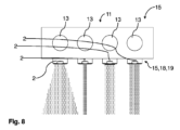
衛生モジュールキット1および/または衛生機能アセンブリ15は、少なくとも2つの流出エレメント2、好適には図2、図7および図8に示した互いに異なる2つの流出エレメント2を有している。特に、これらの流出エレメント2は、異なる流量クラスおよび/または噴射流形状および/または噴射流タイプを有していてよい。流出エレメント2は、少なくとも1つの制御エレメント3に選択的に接続可能であるか、または接続されている(図2、図7および図8を参照)。
The
図4には、電流発生器9を有する実施バリエーションが示されている。補足的に、この電流発生器9は、電気的な中間貯蔵器14を備えていてよく、この電気的な中間貯蔵器14は流出エレメント2を備える水循環路19に作用接続可能であるか、または作用接続されている。たとえば、電流発生器9は、衛生モジュールキット1の消費器または外部の消費器、たとえば特にライト21、特に家具照明に電力供給するために機能することができる。電流発生器9は、制御エレメント3および/または結合エレメント4および/または流出エレメント2に流体接続可能であるか、または流体接続されていてよい。
FIG. 4 shows an implementation variant with a current generator 9 . Additionally, this current generator 9 may comprise an electrical intermediate reservoir 14, which can be operatively connected to the water circuit 19 comprising the
図1~図5に示した衛生機能アセンブリ15および/または家具17および/または衛生機能アセンブリ15を含む衛生設備18はそれぞれ、少なくとも1つの流出エレメント2と、少なくとも1つの制御エレメント3と、流出エレメント2を制御エレメント3に流体接続している少なくとも1つの結合エレメント4とを有しており、互いに異なる少なくとも2つの制御エレメント3が存在しており、制御エレメント3が流体的に並列または直列に配置されており、かつ/または、各制御エレメント3に、個別の流出エレメント2および/または1つの共通の流出エレメントが対応配置されている。
Sanitary installation 18 comprising
図2に示した実施バリエーションでは、2つの制御エレメント3に、1つの共通の分配エレメント5から供給が行われる。
In the embodiment variant shown in FIG. 2, two
図1~図5に示した実施バリエーションでは、機能支持体11がそれぞれ1つの衛生機能アセンブリ15を備えている。
In the embodiment variants shown in FIGS. 1 to 5, the
図7と図8には、互いに異なって形成されたそれぞれ複数の、特に4つの流出エレメント2を備えた実施バリエーションが示されている。たとえば、流出エレメント2は、互いに異なって成形された噴射流形状を形成するように構成されていてよい。特に、流出エレメントは、泡沫(belueftet)、泡沫なし、パルス状、噴霧、連続、CO2添加(機能ユニットを介して実現することも可能)、濾過(機能ユニットを介して実現することも可能)、非濾過、蒸留(機能ユニットを介して実現することも可能)から選択された少なくとも1つまたは複数の噴射流形状を形成するように構成されていてよい。これに対して代替的または付加的には、特に通流式ヒータ8として構成された機能ユニットが設けられている場合、噴射流は加熱されていてもよいし、加熱されていなくてもよい。さらに代替的または付加的には、特に、通流式クーラとして構成された機能ユニットが設けられている場合、噴射流は冷却されていてよい。
FIGS. 7 and 8 show an embodiment variant with a plurality of, in particular four
制御エレメント3は、たとえば手動操作エレメント13を介して手動で操作することができる。制御エレメント3は、好適には手動操作エレメント13によって調整可能である弁を備えていてよい。手動操作エレメント13は、たとえば、オン-オフ-ボタンとして構成されていてよく、かつ/または、プッシュ-プッシュ調節機構(ボールペンと同様に、押すことによってのみ制御される)に接続されていてよい。代替的または付加的には、手動操作エレメント13は、回転によって調節することができ、かつ/または、流量は、弁によって調整することができる。
また、制御エレメント3を、自動化して調整することもできる。特に、制御エレメント3は、測定値に依存した、特に自動化された調整、特に温度敏感な調整を行うために、センサ6、特に温度センサに接続されていてよい。
The
図9は、本発明による別の衛生機能アセンブリ15を示している。上述の実施例に対して機能的および/または構造的に類似または同一の構成部材および機能ユニットは、同一の参照符号で示されており、もう一度別個に説明することはない。したがって、図1~図8に関する説明は、図9にも対応して当てはまる。
Figure 9 shows another
図9に示した実施例では、3つの供給接続部16、つまり冷水接続部24、温水接続部25、熱湯接続部26が存在している。熱湯接続部26に加えて、かつ/または熱湯接続部26の代わりに、炭酸を含ませた水、飲料水、特に浄化水および/または石鹸、オイル、乳液等のような別の流体のための接続部も存在していてよい。
In the embodiment shown in FIG. 9, there are three
温水接続部25および冷水接続部24は、混合器27として、たとえば二方向弁として構成されている1つの共通の制御エレメント3へとガイドされている。混合器27は、遮断弁として構成されている制御エレメント3へとガイドされている。
The hot water connection 25 and the cold water connection 24 are guided as mixer 27 to one
熱湯接続部26は、同様に遮断弁として構成されている別の制御エレメント3へガイドされている。
The hot water connection 26 leads to another
両制御エレメント3は、合流器23、たとえば逆方向に作動する分配器5に接続されている。合流器23は、両方の流体を1つの共通の流出エレメント2へとガイドする。したがって、制御エレメント3は並列に配置されている。
Both
別の実施例では、熱湯接続部26の代わりに温水接続部が形成されている一方で、図9に示した温水接続部25および混合器27は存在していない。 In another embodiment, a hot water connection is formed instead of hot water connection 26, while hot water connection 25 and mixer 27 shown in FIG. 9 are not present.
この場合、制御エレメント3が、好適には無段階にまたは細かい段階付けで調節可能な開口を備えた弁として構成されている場合、混合器は、エレメントの個別の構成要素から実現されている。このことから、衛生モジュールキット1が、混合器の機能を実現するために、必ずしも混合器を有している必要がないことがわかる。
In this case, if the
図10は、本発明に係る別の衛生機能アセンブリ15を示している。上述の実施例に対して機能的および/または構造的に類似または同一の構成部材および機能ユニットは、同一の参照符号で示されており、もう一度別個に説明することはない。したがって、図1~図9に関する説明は、図10にも対応して当てはまる。
Figure 10 shows another
供給接続部16は、遮断弁としての制御エレメント3と切換器22としての制御エレメント3との直列配置へガイドされている。切換器22は、2つまたは3つ(または3つよりも多くの)の切換位置を有していてよく、たとえば2つ(または2つよりも多く)の流出エレメント2のそれぞれへの少なくとも2つの切換位置および/または両方の流出エレメント2への共通の第3の切換位置を有していてよい。
The
図11は、本発明に係る別の衛生機能アセンブリ15を示しており、この衛生機能アセンブリ15は、図9に示した構成と同様に、3つの供給接続部16を有している。供給接続部の個数は、3つよりも多い数にも3つにも少ない数にも容易に変更可能である。たとえば、供給接続部24は冷水接続部、供給接続部25は炭酸水接続部、つまり炭酸を含ませた水のための接続部、供給接続部26は熱湯接続部、特に沸騰した水のための接続部であってよい。各供給接続部16は、結合エレメント4を介して制御エレメント3に接続されている。この例では、すべての制御エレメント3は遮断弁として構成されており、遮断弁は、手動操作エレメント13、(たとえば、プッシュ-プッシュ機構を有する)押しボタンなどを介して制御可能である。
FIG. 11 shows another
この構成は、3つの流出エレメント2をさらに有しており、これらの流出エレメント2はそれぞれ、結合エレメント4を介して制御エレメント3のうちの1つに接続されている。したがって、各供給接続部16は、別個の流出エレメント2へガイドされている。これによって、様々な飲料が厳密に分離されている飲料ステーションなどを形成することができる。これにより、改善された対応配置が可能であり、空間的な分離を行うことができる。
The arrangement furthermore has three
機能アセンブリ15は、たとえば、図7に示したように構成されていてよい。
図6は、本発明に係る衛生モジュールキット1の構成部材を例示的に示しており、この構成部材から、説明した衛生機能アセンブリ15を形成することができる。ここでは、アイデアを説明するために、それぞれ限られた数の構成部材のコピーのみが示されている。結合エレメント4を接続するための接続箇所28がそれぞれ確認可能である。
FIG. 6 exemplarily shows the components of the
つまり、本発明は特に、少なくとも1つの流出エレメント2と、少なくとも1つの制御エレメント3と、流出エレメント2を制御エレメント3に流体接続することができる少なくとも1つの結合エレメント4と、を備えた衛生モジュールキット1であって、機能的に異なる少なくとも2つの制御エレメント3が含まれており、制御エレメント3は、個別にまたは一緒に流出エレメントに選択的に流体接続可能である。
Thus, the invention is in particular a sanitary module with at least one
1 衛生モジュールキット
2 流出エレメント
3 制御エレメント
4 結合エレメント
5 分配器
6 センサ
7 アクチュエータ
8 通流式ヒータ
9 電流発生器
10 取付けエレメント
11 機能支持体
12 分岐エレメント
13 手動操作エレメント
14 電気的な貯蔵器
15 衛生機能アセンブリ
16 供給接続部
17 家具
18 衛生設備
19 水循環路;水道管システム
20 通路
21 ライト
22 切換器
23 合流器
24 冷水接続部
25 温水接続部
26 熱湯接続部
27 混合器
28 差込み箇所
1
Claims (29)
好適には機能的に異なる少なくとも2つの制御エレメント(3)が存在しており、該制御エレメント(3)は前記流出エレメント(2)に選択的に流体接続可能であることを特徴とする、衛生モジュールキット(1)。 at least one outflow element (2), at least one control element (3) and at least one coupling element (4) capable of fluidly connecting said outflow element (2) to said control element (3); A hygiene module kit (1) comprising
Sanitary, preferably characterized in that there are at least two functionally different control elements (3), which are selectively fluidly connectable to said outflow element (2). Module kit (1).
少なくとも1つの分配器(5)が存在しており、前記分配器(5)に、好適には機能的に異なる少なくとも2つの制御エレメント(3)、結合エレメント(4)および/または流出エレメント(2)が同時に接続可能であることを特徴とする、衛生モジュールキット(1)。 at least one outflow element (2), at least one control element (3) and at least one coupling element (4) capable of fluidly connecting said outflow element (2) to said control element (3); Hygienic module kit (1), in particular according to claim 1, comprising
There is at least one distributor (5) in which preferably at least two functionally different control elements (3), coupling elements (4) and/or outflow elements (2 ) can be connected simultaneously.
互いに異なる少なくとも2つの制御エレメント(3)が存在しており、前記制御エレメント(3)が流体的に並列または直列に配置されており、かつ/または、各制御エレメント(3)に、個別の流出エレメント(2)および/または1つの共通の流出エレメント(2)が対応配置されていることを特徴とする、衛生機能アセンブリ(15)。 with at least one outflow element (2), at least one control element (3) and at least one coupling element (4) fluidly connecting said outflow element (2) to said control element (3) , in particular a sanitary functional assembly (15) comprising a sanitary module kit (1) according to any one of claims 1 to 13,
There are at least two control elements (3) different from each other, said control elements (3) being arranged fluidically in parallel or in series and/or each control element (3) having a separate outflow Sanitary function assembly (15), characterized in that the elements (2) and/or one common outflow element (2) are associated.
好適には互いに異なる少なくとも2つの流出エレメント(2)が存在しており、前記流出エレメント(2)が流体的に並列または直列に配置されており、かつ/または、各流出エレメント(2)に、個別の制御エレメント(3)および/または1つの共通の制御エレメント(3)が対応配置されていることを特徴とする、衛生機能アセンブリ(15)。 with at least one outflow element (2), at least one control element (3) and at least one coupling element (4) fluidly connecting said outflow element (2) to said control element (3) a hygiene functional assembly (15), in particular according to claim 14 and/or consisting of a hygiene module kit (1) according to any one of claims 1 to 13,
There are preferably at least two outflow elements (2) different from each other, said outflow elements (2) being arranged fluidically in parallel or in series and/or each outflow element (2) Sanitary function assembly (15), characterized in that individual control elements (3) and/or one common control element (3) are associated.
前記機能支持体(11)の少なくとも1つの寸法を入力し、所望の機能範囲を入力し、少なくとも1つの流出エレメント(2)、少なくとも1つの制御エレメント(3)および少なくとも1つの結合エレメント(4)を、請求項1から13までのいずれか1項記載の衛生モジュールキット(1)から選択して、前記所望の機能範囲が実現されるように配管図を作成し、少なくとも1つの寸法内で前記衛生モジュールキット(1)の選択された前記エレメントを配置するためのレイアウトを作成し、前記機能アセンブリ(15)を製造するために、前記レイアウトにしたがって前記機能支持体(11)を加工することを特徴とする、方法。 A method of manufacturing a sanitary functional assembly (15), in particular according to any one of claims 14 to 17, comprising equipping a functional support (11) with said functional assembly (15), comprising:
Entering at least one dimension of said functional support (11), entering the desired functional area, at least one outflow element (2), at least one control element (3) and at least one coupling element (4) from the sanitary module kit (1) according to any one of claims 1 to 13 to construct a piping diagram such that the desired functional range is realized, and within at least one dimension the creating a layout for arranging said selected elements of a sanitary module kit (1) and processing said functional support (11) according to said layout to produce said functional assembly (15). A method characterized by:
Applications Claiming Priority (3)
| Application Number | Priority Date | Filing Date | Title |
|---|---|---|---|
| DE202020102039.0U DE202020102039U1 (en) | 2020-04-14 | 2020-04-14 | Sanitary construction kit and sanitary functional arrangement |
| DE202020102039.0 | 2020-04-14 | ||
| PCT/EP2021/057150 WO2021209224A1 (en) | 2020-04-14 | 2021-03-19 | Sanitary kit, sanitary functional arrangement and method for producing a sanitary functional arrangement |
Publications (1)
| Publication Number | Publication Date |
|---|---|
| JP2023521950A true JP2023521950A (en) | 2023-05-26 |
Family
ID=75203280
Family Applications (1)
| Application Number | Title | Priority Date | Filing Date |
|---|---|---|---|
| JP2022555671A Pending JP2023521950A (en) | 2020-04-14 | 2021-03-19 | Sanitary module kit, sanitary functional assembly, method of manufacturing sanitary functional assembly |
Country Status (7)
| Country | Link |
|---|---|
| US (1) | US12331497B2 (en) |
| EP (2) | EP3969676A1 (en) |
| JP (1) | JP2023521950A (en) |
| CN (3) | CN213296524U (en) |
| BR (1) | BR112022014724A2 (en) |
| DE (1) | DE202020102039U1 (en) |
| WO (1) | WO2021209224A1 (en) |
Families Citing this family (1)
| Publication number | Priority date | Publication date | Assignee | Title |
|---|---|---|---|---|
| DE202020102039U1 (en) | 2020-04-14 | 2021-07-15 | Neoperl Gmbh | Sanitary construction kit and sanitary functional arrangement |
Family Cites Families (23)
| Publication number | Priority date | Publication date | Assignee | Title |
|---|---|---|---|---|
| US4654900A (en) * | 1985-11-21 | 1987-04-07 | Mcghee Charles M | Bathtub valve fixture module |
| US4731545A (en) * | 1986-03-14 | 1988-03-15 | Desai & Lerner | Portable self-contained power conversion unit |
| US5133094A (en) * | 1991-07-15 | 1992-07-28 | Clarke Jr Thomas H | Tub/shower valve locating fixture |
| US5375887A (en) * | 1993-06-21 | 1994-12-27 | Johnson; Dwight N. | Plumbing hookup kit |
| DE9402093U1 (en) | 1994-02-08 | 1994-03-31 | Bürkert Werke GmbH & Co., 74653 Ingelfingen | Modular valve and distributor system for flowing media |
| DE4443081A1 (en) | 1994-12-03 | 1996-06-05 | Mueller A & K Gmbh Co Kg | Device for interconnecting several solenoid valves |
| DE10339096A1 (en) | 2003-08-22 | 2005-03-10 | Grohe Water Tech Ag & Co Kg | Modular valve and distribution system |
| DE10343249A1 (en) | 2003-09-17 | 2005-04-21 | Grohe Water Tech Ag & Co Kg | Modular construction valve systems especially for sanitary applications has the modules assembled between two support rails and with interlocking connections |
| DE102004005161A1 (en) * | 2004-02-02 | 2005-08-18 | Grohe Water Technology Ag & Co. Kg | Mounting system for sanitary fitting in bathroom has rectangular frame sunk into wall and has connections for hot and cold water regulating taps and has wire with electrical connections |
| DE102006033352B4 (en) * | 2006-07-19 | 2011-06-22 | Hansa Metallwerke AG, 70567 | Sanitary concealed fitting with a base body |
| DE102007012946A1 (en) | 2007-03-14 | 2008-09-18 | Klein, Rainer, Prof. Dr.-Ing. | Outlet fitting e.g. tap, adapter for signaling temperature of draining fluid, has multi color LEDs displaying temperature of fluid, where radiation intensity of LEDs are changed depending on temperature |
| JP4140062B1 (en) * | 2007-07-23 | 2008-08-27 | Toto株式会社 | Faucet generator |
| WO2009013882A1 (en) * | 2007-07-23 | 2009-01-29 | Toto Ltd. | Generator for faucet |
| JP2009108990A (en) | 2007-11-01 | 2009-05-21 | Maezawa Kyuso Industries Co Ltd | Housing water piping and prefabricated piping members |
| DE102009060501B3 (en) * | 2009-12-23 | 2011-06-22 | Neoperl GmbH, 79379 | Sanitary outlet unit |
| US9816634B2 (en) * | 2011-03-15 | 2017-11-14 | Aquis Sanitaer Ag | Sanitary fitting having a fitting housing and a control unit |
| CN105422962B (en) * | 2013-11-08 | 2018-09-18 | 广州海鸥住宅工业股份有限公司 | A kind of working method of the universal capacitor-type touch inductive switch component of tap |
| CN203784364U (en) * | 2014-01-16 | 2014-08-20 | 杨蓓 | Shunt valve with ceramic valve core for intelligent sanitary equipment |
| CN104019254B (en) * | 2014-06-19 | 2017-03-29 | 泉州安科卫浴有限公司 | A kind of button shower |
| US10378189B2 (en) * | 2015-05-29 | 2019-08-13 | Component Hardware Group, Inc. | Sink and faucet assembly |
| US9631348B2 (en) * | 2015-07-02 | 2017-04-25 | Xiamen EASO Co., Ltd. | Water saving control mechanism |
| DE202020102039U1 (en) * | 2020-04-14 | 2021-07-15 | Neoperl Gmbh | Sanitary construction kit and sanitary functional arrangement |
| DE202021101419U1 (en) * | 2021-03-19 | 2022-06-21 | Neoperl GmbH | Fluidic outflow unit and associated uses |
-
2020
- 2020-04-14 DE DE202020102039.0U patent/DE202020102039U1/en active Active
- 2020-07-09 CN CN202021342748.7U patent/CN213296524U/en active Active
- 2020-07-09 CN CN202010658028.XA patent/CN113529870B/en active Active
-
2021
- 2021-03-19 EP EP21714133.2A patent/EP3969676A1/en active Pending
- 2021-03-19 US US17/914,802 patent/US12331497B2/en active Active
- 2021-03-19 WO PCT/EP2021/057150 patent/WO2021209224A1/en not_active Ceased
- 2021-03-19 JP JP2022555671A patent/JP2023521950A/en active Pending
- 2021-03-19 BR BR112022014724A patent/BR112022014724A2/en unknown
- 2021-03-19 CN CN202180017714.1A patent/CN115190931A/en active Pending
- 2021-03-19 EP EP23193077.7A patent/EP4273332A3/en not_active Withdrawn
Also Published As
| Publication number | Publication date |
|---|---|
| US20230146601A1 (en) | 2023-05-11 |
| CN115190931A (en) | 2022-10-14 |
| EP3969676A1 (en) | 2022-03-23 |
| CN113529870A (en) | 2021-10-22 |
| WO2021209224A1 (en) | 2021-10-21 |
| EP4273332A3 (en) | 2024-03-13 |
| US12331497B2 (en) | 2025-06-17 |
| BR112022014724A2 (en) | 2022-10-25 |
| CN113529870B (en) | 2023-07-18 |
| CN213296524U (en) | 2021-05-28 |
| EP4273332A2 (en) | 2023-11-08 |
| DE202020102039U1 (en) | 2021-07-15 |
Similar Documents
| Publication | Publication Date | Title |
|---|---|---|
| US10577784B2 (en) | Shower head with integrated mixing valve | |
| US7077153B2 (en) | Side control faucet with diverter assembly | |
| JP7068346B2 (en) | Integrated mixed tap water and conditioned water faucet assembly with pull-out sprayer head | |
| TWI803453B (en) | Mixing tap for dispensing water | |
| US20060214016A1 (en) | Hands-free faucet | |
| US7096879B2 (en) | Pillar sink mixer with hand spray | |
| CN101099955A (en) | Spray head with simplified braking device | |
| JP2023521950A (en) | Sanitary module kit, sanitary functional assembly, method of manufacturing sanitary functional assembly | |
| US20240158218A1 (en) | Fluidic outflow unit and associated uses | |
| CN110773339B (en) | Sanitary shower device | |
| CN111156333B (en) | A water mixing valve | |
| WO2012140526A2 (en) | A tap group for dispensing a filtered liquid and a non- filtered liquid | |
| KR20090001771U (en) | Faucet bracket with 3-way valve | |
| JP2006169762A (en) | Branch connector | |
| WO2019122803A1 (en) | A flow dispersion device | |
| GB2601706A (en) | A flow dispersion device |