JP2023517618A - Endoscope device with movable camera - Google Patents
Endoscope device with movable camera Download PDFInfo
- Publication number
- JP2023517618A JP2023517618A JP2022554642A JP2022554642A JP2023517618A JP 2023517618 A JP2023517618 A JP 2023517618A JP 2022554642 A JP2022554642 A JP 2022554642A JP 2022554642 A JP2022554642 A JP 2022554642A JP 2023517618 A JP2023517618 A JP 2023517618A
- Authority
- JP
- Japan
- Prior art keywords
- tissue
- camera
- anvil
- endoscope
- endoscopic device
- Prior art date
- Legal status (The legal status is an assumption and is not a legal conclusion. Google has not performed a legal analysis and makes no representation as to the accuracy of the status listed.)
- Pending
Links
- 238000003780 insertion Methods 0.000 claims abstract description 42
- 230000037431 insertion Effects 0.000 claims abstract description 42
- 238000000034 method Methods 0.000 claims abstract description 33
- 230000012010 growth Effects 0.000 claims description 35
- 238000002271 resection Methods 0.000 claims description 5
- 238000010304 firing Methods 0.000 claims description 3
- 238000007689 inspection Methods 0.000 claims description 3
- 238000005286 illumination Methods 0.000 description 20
- 238000010586 diagram Methods 0.000 description 18
- 230000033001 locomotion Effects 0.000 description 10
- 238000012800 visualization Methods 0.000 description 6
- 230000008569 process Effects 0.000 description 5
- 208000037062 Polyps Diseases 0.000 description 4
- 230000007246 mechanism Effects 0.000 description 4
- 230000003213 activating effect Effects 0.000 description 3
- 230000003287 optical effect Effects 0.000 description 3
- 206010028980 Neoplasm Diseases 0.000 description 2
- 238000013461 design Methods 0.000 description 2
- 239000000835 fiber Substances 0.000 description 2
- 239000012781 shape memory material Substances 0.000 description 2
- 230000002159 abnormal effect Effects 0.000 description 1
- 230000006978 adaptation Effects 0.000 description 1
- 238000013459 approach Methods 0.000 description 1
- 230000008859 change Effects 0.000 description 1
- 238000001839 endoscopy Methods 0.000 description 1
- 125000001475 halogen functional group Chemical group 0.000 description 1
- 230000002262 irrigation Effects 0.000 description 1
- 238000003973 irrigation Methods 0.000 description 1
- 238000012986 modification Methods 0.000 description 1
- 230000004048 modification Effects 0.000 description 1
- 239000013307 optical fiber Substances 0.000 description 1
- 238000004091 panning Methods 0.000 description 1
- 238000001356 surgical procedure Methods 0.000 description 1
- 210000001835 viscera Anatomy 0.000 description 1
Images


Classifications
-
- A—HUMAN NECESSITIES
- A61—MEDICAL OR VETERINARY SCIENCE; HYGIENE
- A61B—DIAGNOSIS; SURGERY; IDENTIFICATION
- A61B1/00—Instruments for performing medical examinations of the interior of cavities or tubes of the body by visual or photographical inspection, e.g. endoscopes; Illuminating arrangements therefor
- A61B1/04—Instruments for performing medical examinations of the interior of cavities or tubes of the body by visual or photographical inspection, e.g. endoscopes; Illuminating arrangements therefor combined with photographic or television appliances
- A61B1/05—Instruments for performing medical examinations of the interior of cavities or tubes of the body by visual or photographical inspection, e.g. endoscopes; Illuminating arrangements therefor combined with photographic or television appliances characterised by the image sensor, e.g. camera, being in the distal end portion
- A61B1/053—Instruments for performing medical examinations of the interior of cavities or tubes of the body by visual or photographical inspection, e.g. endoscopes; Illuminating arrangements therefor combined with photographic or television appliances characterised by the image sensor, e.g. camera, being in the distal end portion being detachable
-
- A—HUMAN NECESSITIES
- A61—MEDICAL OR VETERINARY SCIENCE; HYGIENE
- A61B—DIAGNOSIS; SURGERY; IDENTIFICATION
- A61B1/00—Instruments for performing medical examinations of the interior of cavities or tubes of the body by visual or photographical inspection, e.g. endoscopes; Illuminating arrangements therefor
- A61B1/00163—Optical arrangements
- A61B1/00174—Optical arrangements characterised by the viewing angles
- A61B1/00177—Optical arrangements characterised by the viewing angles for 90 degrees side-viewing
-
- A—HUMAN NECESSITIES
- A61—MEDICAL OR VETERINARY SCIENCE; HYGIENE
- A61B—DIAGNOSIS; SURGERY; IDENTIFICATION
- A61B1/00—Instruments for performing medical examinations of the interior of cavities or tubes of the body by visual or photographical inspection, e.g. endoscopes; Illuminating arrangements therefor
- A61B1/00163—Optical arrangements
- A61B1/00174—Optical arrangements characterised by the viewing angles
- A61B1/00183—Optical arrangements characterised by the viewing angles for variable viewing angles
-
- A—HUMAN NECESSITIES
- A61—MEDICAL OR VETERINARY SCIENCE; HYGIENE
- A61B—DIAGNOSIS; SURGERY; IDENTIFICATION
- A61B1/00—Instruments for performing medical examinations of the interior of cavities or tubes of the body by visual or photographical inspection, e.g. endoscopes; Illuminating arrangements therefor
- A61B1/04—Instruments for performing medical examinations of the interior of cavities or tubes of the body by visual or photographical inspection, e.g. endoscopes; Illuminating arrangements therefor combined with photographic or television appliances
- A61B1/045—Control thereof
-
- A—HUMAN NECESSITIES
- A61—MEDICAL OR VETERINARY SCIENCE; HYGIENE
- A61B—DIAGNOSIS; SURGERY; IDENTIFICATION
- A61B1/00—Instruments for performing medical examinations of the interior of cavities or tubes of the body by visual or photographical inspection, e.g. endoscopes; Illuminating arrangements therefor
- A61B1/04—Instruments for performing medical examinations of the interior of cavities or tubes of the body by visual or photographical inspection, e.g. endoscopes; Illuminating arrangements therefor combined with photographic or television appliances
- A61B1/05—Instruments for performing medical examinations of the interior of cavities or tubes of the body by visual or photographical inspection, e.g. endoscopes; Illuminating arrangements therefor combined with photographic or television appliances characterised by the image sensor, e.g. camera, being in the distal end portion
-
- A—HUMAN NECESSITIES
- A61—MEDICAL OR VETERINARY SCIENCE; HYGIENE
- A61B—DIAGNOSIS; SURGERY; IDENTIFICATION
- A61B1/00—Instruments for performing medical examinations of the interior of cavities or tubes of the body by visual or photographical inspection, e.g. endoscopes; Illuminating arrangements therefor
- A61B1/06—Instruments for performing medical examinations of the interior of cavities or tubes of the body by visual or photographical inspection, e.g. endoscopes; Illuminating arrangements therefor with illuminating arrangements
-
- A—HUMAN NECESSITIES
- A61—MEDICAL OR VETERINARY SCIENCE; HYGIENE
- A61B—DIAGNOSIS; SURGERY; IDENTIFICATION
- A61B17/00—Surgical instruments, devices or methods
- A61B17/068—Surgical staplers, e.g. containing multiple staples or clamps
- A61B17/072—Surgical staplers, e.g. containing multiple staples or clamps for applying a row of staples in a single action, e.g. the staples being applied simultaneously
-
- A—HUMAN NECESSITIES
- A61—MEDICAL OR VETERINARY SCIENCE; HYGIENE
- A61B—DIAGNOSIS; SURGERY; IDENTIFICATION
- A61B17/00—Surgical instruments, devices or methods
- A61B17/32—Surgical cutting instruments
- A61B17/320016—Endoscopic cutting instruments, e.g. arthroscopes, resectoscopes
- A61B17/32002—Endoscopic cutting instruments, e.g. arthroscopes, resectoscopes with continuously rotating, oscillating or reciprocating cutting instruments
-
- A—HUMAN NECESSITIES
- A61—MEDICAL OR VETERINARY SCIENCE; HYGIENE
- A61B—DIAGNOSIS; SURGERY; IDENTIFICATION
- A61B18/00—Surgical instruments, devices or methods for transferring non-mechanical forms of energy to or from the body
- A61B18/04—Surgical instruments, devices or methods for transferring non-mechanical forms of energy to or from the body by heating
- A61B18/08—Surgical instruments, devices or methods for transferring non-mechanical forms of energy to or from the body by heating by means of electrically-heated probes
-
- A—HUMAN NECESSITIES
- A61—MEDICAL OR VETERINARY SCIENCE; HYGIENE
- A61B—DIAGNOSIS; SURGERY; IDENTIFICATION
- A61B17/00—Surgical instruments, devices or methods
- A61B17/00234—Surgical instruments, devices or methods for minimally invasive surgery
- A61B2017/00238—Type of minimally invasive operation
- A61B2017/00278—Transorgan operations, e.g. transgastric
-
- A—HUMAN NECESSITIES
- A61—MEDICAL OR VETERINARY SCIENCE; HYGIENE
- A61B—DIAGNOSIS; SURGERY; IDENTIFICATION
- A61B17/00—Surgical instruments, devices or methods
- A61B17/00234—Surgical instruments, devices or methods for minimally invasive surgery
- A61B2017/00292—Surgical instruments, devices or methods for minimally invasive surgery mounted on or guided by flexible, e.g. catheter-like, means
- A61B2017/00296—Surgical instruments, devices or methods for minimally invasive surgery mounted on or guided by flexible, e.g. catheter-like, means mounted on an endoscope
-
- A—HUMAN NECESSITIES
- A61—MEDICAL OR VETERINARY SCIENCE; HYGIENE
- A61B—DIAGNOSIS; SURGERY; IDENTIFICATION
- A61B17/00—Surgical instruments, devices or methods
- A61B17/00234—Surgical instruments, devices or methods for minimally invasive surgery
- A61B2017/00292—Surgical instruments, devices or methods for minimally invasive surgery mounted on or guided by flexible, e.g. catheter-like, means
- A61B2017/003—Steerable
-
- A—HUMAN NECESSITIES
- A61—MEDICAL OR VETERINARY SCIENCE; HYGIENE
- A61B—DIAGNOSIS; SURGERY; IDENTIFICATION
- A61B17/00—Surgical instruments, devices or methods
- A61B17/00234—Surgical instruments, devices or methods for minimally invasive surgery
- A61B2017/00349—Needle-like instruments having hook or barb-like gripping means, e.g. for grasping suture or tissue
-
- A—HUMAN NECESSITIES
- A61—MEDICAL OR VETERINARY SCIENCE; HYGIENE
- A61B—DIAGNOSIS; SURGERY; IDENTIFICATION
- A61B17/00—Surgical instruments, devices or methods
- A61B2017/00535—Surgical instruments, devices or methods pneumatically or hydraulically operated
-
- A—HUMAN NECESSITIES
- A61—MEDICAL OR VETERINARY SCIENCE; HYGIENE
- A61B—DIAGNOSIS; SURGERY; IDENTIFICATION
- A61B17/00—Surgical instruments, devices or methods
- A61B17/068—Surgical staplers, e.g. containing multiple staples or clamps
- A61B17/072—Surgical staplers, e.g. containing multiple staples or clamps for applying a row of staples in a single action, e.g. the staples being applied simultaneously
- A61B2017/07214—Stapler heads
- A61B2017/07221—Stapler heads curved
-
- A—HUMAN NECESSITIES
- A61—MEDICAL OR VETERINARY SCIENCE; HYGIENE
- A61B—DIAGNOSIS; SURGERY; IDENTIFICATION
- A61B17/00—Surgical instruments, devices or methods
- A61B17/068—Surgical staplers, e.g. containing multiple staples or clamps
- A61B17/072—Surgical staplers, e.g. containing multiple staples or clamps for applying a row of staples in a single action, e.g. the staples being applied simultaneously
- A61B2017/07214—Stapler heads
- A61B2017/07228—Arrangement of the staples
-
- A—HUMAN NECESSITIES
- A61—MEDICAL OR VETERINARY SCIENCE; HYGIENE
- A61B—DIAGNOSIS; SURGERY; IDENTIFICATION
- A61B17/00—Surgical instruments, devices or methods
- A61B17/068—Surgical staplers, e.g. containing multiple staples or clamps
- A61B17/072—Surgical staplers, e.g. containing multiple staples or clamps for applying a row of staples in a single action, e.g. the staples being applied simultaneously
- A61B2017/07214—Stapler heads
- A61B2017/07271—Stapler heads characterised by its cartridge
-
- A—HUMAN NECESSITIES
- A61—MEDICAL OR VETERINARY SCIENCE; HYGIENE
- A61B—DIAGNOSIS; SURGERY; IDENTIFICATION
- A61B18/00—Surgical instruments, devices or methods for transferring non-mechanical forms of energy to or from the body
- A61B2018/00571—Surgical instruments, devices or methods for transferring non-mechanical forms of energy to or from the body for achieving a particular surgical effect
- A61B2018/00601—Cutting
-
- A—HUMAN NECESSITIES
- A61—MEDICAL OR VETERINARY SCIENCE; HYGIENE
- A61B—DIAGNOSIS; SURGERY; IDENTIFICATION
- A61B90/00—Instruments, implements or accessories specially adapted for surgery or diagnosis and not covered by any of the groups A61B1/00 - A61B50/00, e.g. for luxation treatment or for protecting wound edges
- A61B90/30—Devices for illuminating a surgical field, the devices having an interrelation with other surgical devices or with a surgical procedure
-
- A—HUMAN NECESSITIES
- A61—MEDICAL OR VETERINARY SCIENCE; HYGIENE
- A61B—DIAGNOSIS; SURGERY; IDENTIFICATION
- A61B90/00—Instruments, implements or accessories specially adapted for surgery or diagnosis and not covered by any of the groups A61B1/00 - A61B50/00, e.g. for luxation treatment or for protecting wound edges
- A61B90/36—Image-producing devices or illumination devices not otherwise provided for
- A61B90/361—Image-producing devices, e.g. surgical cameras
Landscapes
- Health & Medical Sciences (AREA)
- Life Sciences & Earth Sciences (AREA)
- Surgery (AREA)
- General Health & Medical Sciences (AREA)
- Public Health (AREA)
- Veterinary Medicine (AREA)
- Nuclear Medicine, Radiotherapy & Molecular Imaging (AREA)
- Animal Behavior & Ethology (AREA)
- Molecular Biology (AREA)
- Engineering & Computer Science (AREA)
- Biomedical Technology (AREA)
- Heart & Thoracic Surgery (AREA)
- Medical Informatics (AREA)
- Biophysics (AREA)
- Radiology & Medical Imaging (AREA)
- Physics & Mathematics (AREA)
- Pathology (AREA)
- Optics & Photonics (AREA)
- Orthopedic Medicine & Surgery (AREA)
- Endoscopes (AREA)
- Surgical Instruments (AREA)
Abstract
挿入チューブと、遠位先端と、遠位先端または挿入チューブの上もしくは中の初期位置に配置された少なくとも1つのカメラとを備える、内視鏡デバイスが開示される。内視鏡デバイスは、内視鏡デバイスの近位端から活性化される機械的装置を備え、機械的装置は、(a)少なくとも1つのカメラを初期位置から、遠位先端または挿入チューブの上の、中の、もしくはそこから離隔された、1つまたは複数の異なる位置へと移動させること、ならびに(b)少なくとも1つのカメラの観察方向を変更すること、のうちの少なくとも1つを行うように構成されることを特徴とする。また、内視鏡デバイスの実施形態を使用して内視鏡処置を実施する方法が開示される。【選択図】なしAn endoscopic device is disclosed that includes an insertion tube, a distal tip, and at least one camera disposed in an initial position on or in the distal tip or insertion tube. The endoscopic device includes a mechanical device that is activated from the proximal end of the endoscopic device, the mechanical device (a) moving at least one camera from an initial position over the distal tip or insertion tube. to one or more different positions within, within, or spaced from; and (b) changing the viewing direction of at least one camera. It is characterized by being configured to Also disclosed is a method of performing an endoscopic procedure using embodiments of the endoscopic device. [Selection figure] None
Description
本発明は、内視鏡デバイスの分野に関する。特に、本発明は、内視鏡デバイスに設けられた可視化手段に関する。 The present invention relates to the field of endoscopic devices. In particular, the invention relates to visualization means provided on an endoscopic device.
内視鏡デバイスは、ハンドル(制御部分)と、挿入チューブ(挿入軸)と、一般的には、遠位面の可視化および照明手段と、可視化手段によって獲得された画像を表示デバイスに送信する手段と、を備えるデバイスである。挿入軸は、剛性、可撓性、またはそれらの組み合わせのいずれかであり得る。挿入軸はまた、関節部分を備えることができる。 An endoscopic device comprises a handle (control portion), an insertion tube (insertion shaft), generally distal face visualization and illumination means, and means for transmitting images acquired by the visualization means to a display device. and a device comprising: The insertion shaft can be either rigid, flexible, or a combination thereof. The insertion shaft can also include an articulation portion.
医療処置で使用される内視鏡デバイスは、特に、内視鏡または腹腔鏡として知られている。内視鏡デバイスは、体内臓器を検査するために、小さい切り口を通して、または口などの身体の自然開口を通して、患者の体内に挿入される。内視鏡は、挿入軸に装着されるか、または挿入軸を通る1つもしくは複数の作業チャネルを介して手術位置に導入される、追加のデバイスを用いて、例えば腫瘍またはポリープなどの異常組織の除去など、外科処置を実施するのに使用される。内視鏡デバイス、例えばボアスコープは、工業用途で使用される。本明細書では、内視鏡という単語は、医療用および工業用両方の全てのタイプの内視鏡デバイスを指すのに使用される。 Endoscopic devices used in medical procedures are known inter alia as endoscopes or laparoscopes. Endoscopic devices are inserted into a patient's body through small incisions or through natural openings in the body, such as the mouth, to examine internal organs. The endoscope can be used to detect abnormal tissue, e.g. tumors or polyps, with additional devices mounted on the insertion shaft or introduced into the surgical site via one or more working channels through the insertion shaft. used to perform surgical procedures, such as the removal of Endoscopic devices, such as borescopes, are used in industrial applications. The word endoscope is used herein to refer to all types of endoscopic devices, both medical and industrial.
例えば、CCDまたはCMOS型のスチルカメラもしくはビデオカメラ、光中継システム、光ファイバー、「チップオンスティック(chip on a stick)」など、多くの異なるタイプの可視化手段が、挿入チューブの遠位端から近位端へと近位方向に画像を伝達する、内視鏡検査の分野で知られている。ほとんどの現代の内視鏡デバイスはビデオカメラを備えるので、本明細書(特許請求の範囲を含む)では、カメラという単語はこれらのシステムのいずれかを表すのに使用される。 Many different types of visualization means, such as CCD or CMOS type still or video cameras, optical relay systems, fiber optics, "chip on a stick", etc. It is known in the field of endoscopy for transmitting images proximally to the end. Since most modern endoscopic devices are equipped with video cameras, the word camera is used herein (including the claims) to represent either of these systems.
本発明者らが知っている全ての内視鏡デバイスは、内視鏡の遠位先端または挿入軸のどちらかに固定的に取り付けられた、1つまたは複数のカメラを備える。これらのカメラは、内視鏡の意図される用途に従って予め定められる、観察方向および視野を有する。特定の状況では、この視野または観察方向は、意図されるタスクを実施するのには不適切であり、また他の状況では、視野は、例えば、医療処置の間に操作されている組織がカメラのレンズと外科用器具との間に来ると、部分的または完全に遮断される。これらの状況では、外科医は、「見えない」状態で処置を実施するか、またはより見やすくするために内視鏡デバイスの位置を変えなければならない。したがって、内視鏡デバイスが、様々な視野から画像を取得することができ、内視鏡処置全体を通して内視鏡を回転させたり位置を変えたりする必要なく、継続的な内視鏡観察を維持することができるようにするのが有利であろう。 All endoscopic devices known to the inventors comprise one or more cameras fixedly attached to either the distal tip or the insertion shaft of the endoscope. These cameras have viewing directions and fields of view that are predetermined according to the intended use of the endoscope. In certain circumstances, this field of view or viewing direction may be inappropriate to perform the intended task, and in other circumstances the field of view may be unsuitable for the tissue being manipulated during a medical procedure, for example. It is partially or completely blocked when it comes between the lens and the surgical instrument. In these situations, the surgeon must either perform the procedure "blind" or reposition the endoscopic device for better visibility. Thus, the endoscopic device can acquire images from various fields of view and maintain continuous endoscopic observation without the need to rotate or reposition the endoscope throughout the endoscopic procedure. It would be advantageous to be able to
したがって、本発明の1つの目的は、内視鏡処置の間、複数の観察方向および対応する視野からの画像を提供することができる、内視鏡デバイスを提供することである。 SUMMARY OF THE INVENTION Accordingly, it is an object of the present invention to provide an endoscopic device capable of providing images from multiple viewing directions and corresponding fields of view during an endoscopic procedure.
本発明の別の目的は、内視鏡処置全体を通して継続的な内視鏡観察を維持することができる、内視鏡デバイスを提供することである。 Another object of the present invention is to provide an endoscopic device capable of maintaining continuous endoscopic observation throughout the endoscopic procedure.
本発明の更なる目的および利点は、説明が進むにつれて明らかになるであろう。 Further objects and advantages of the invention will become apparent as the description proceeds.
第1の態様では、本発明は、挿入チューブと、遠位先端と、遠位先端または挿入チューブの上もしくは中の初期位置に配置された少なくとも1つのカメラとを備える、内視鏡デバイスである。内視鏡デバイスは、内視鏡デバイスの近位端から活性化される機械的装置を備え、機械的装置は、
(a)少なくとも1つのカメラを初期位置から、遠位先端または挿入チューブの上の、中の、もしくはそこから離隔された、1つまたは複数の異なる位置へと移動させること、ならびに
(b)少なくとも1つのカメラの観察方向を変更すること、のうちの少なくとも1つを行うように構成されることを特徴とする。
In a first aspect, the invention is an endoscopic device comprising an insertion tube, a distal tip, and at least one camera located in an initial position on or in the distal tip or insertion tube. . The endoscopic device comprises a mechanical device activated from the proximal end of the endoscopic device, the mechanical device comprising:
(a) moving at least one camera from an initial position to one or more different positions on, in, or spaced from the distal tip or insertion tube; and (b) at least changing the viewing direction of one camera.
内視鏡デバイスの実施形態は、内視鏡デバイスの遠位先端または挿入チューブに固定的に取り付けられた、1つまたは複数のカメラを備える第1のセットのカメラと、内視鏡デバイスの遠位先端または挿入チューブから外側へと可逆的に延長されるように構成された少なくとも1つのロッドにそれぞれ装着された、1つまたは複数のカメラを備える第2のセットとを備える。第1のセットのカメラは、内視鏡デバイスの内部から外側を見る観察方向を提供し、第2のセットのカメラは、内視鏡デバイスに向かって内側を見る観察方向を提供する。 Embodiments of the endoscopic device include a first set of cameras comprising one or more cameras fixedly attached to a distal tip or insertion tube of the endoscopic device and a remote camera of the endoscopic device. and a second set comprising one or more cameras each attached to at least one rod configured to reversibly extend outward from the posterior tip or insertion tube. A first set of cameras provides a viewing direction looking outward from inside the endoscopic device and a second set of cameras provides a viewing direction looking inward towards the endoscopic device.
第1および第2のセットのカメラを備える内視鏡デバイスの実施形態では、少なくとも1つのロッドは、内視鏡に固定的に取り付けられたカメラでは得ることができない視野を提供するために、内視鏡の表面に対して任意の方向で可逆的に延長されるように構成することができる。 In embodiments of the endoscopic device comprising first and second sets of cameras, at least one rod is configured to provide a field of view not available with cameras fixedly attached to the endoscope. It can be configured to reversibly extend in any direction with respect to the surface of the scope.
内視鏡デバイスの実施形態では、カメラのうちの少なくとも1つは、内視鏡を回転または移動させることなく様々な視角を提供するために、カメラをパン、チルト、または回転させることができるようなやり方で装着される。 In embodiments of the endoscopic device, at least one of the cameras is capable of panning, tilting, or rotating the camera to provide various viewing angles without rotating or moving the endoscope. worn in a certain way.
第1および第2のセットのカメラを備える内視鏡デバイスの実施形態では、第1のセットのカメラは、遠位先端の遠位面に固定的に取り付けられた、1つの前方に面するカメラを備え、第2のセットのカメラは、基部に当接する第1の位置から、基部から離隔された第2の位置へと延長させ、第2の位置から近位側に後退させて第1の位置に戻すことができる、少なくとも1つのロッドに取り付けられたカメラマウントに装着された、1つの後方に面するカメラを備える。基部は、
a)専用の内視鏡の一体部品であり、少なくとも1つのロッドを中を通して遠位側および近位側に摺動させることができる少なくとも1つのボアを備える、特別に構成された遠位先端、ならびに
b)内視鏡の遠位先端の上を滑動する、遠位先端に取り付けられたカラーであって、少なくとも1つのロッドを中を通して遠位側および近位側に摺動させることができる少なくとも1つのボアを備える、カラー、のうちの1つであることができる。
In embodiments of the endoscopic device comprising first and second sets of cameras, the first set of cameras is one forward-facing camera fixedly attached to the distal face of the distal tip. and a second set of cameras extend from a first position abutting the base to a second position spaced from the base and retracted proximally from the second position to the first position. There is one rear-facing camera mounted on a camera mount attached to at least one rod that can be returned to position. The base is
a) a specially configured distal tip that is an integral part of a dedicated endoscope and comprises at least one bore through which at least one rod can be slid distally and proximally; and b) a collar attached to the distal tip that slides over the distal tip of the endoscope, at least one rod being slidable distally and proximally therethrough. collar, with one bore.
内視鏡デバイスのこの実施形態は、(i)アンビルおよびステープルカートリッジで構成されたステープル留めデバイスであって、アンビルが、遠位側に延長させて開放構成を得ることができる、または近位側に後退させて閉止構成を得ることができる2つのロッドに装着され、ステープルカートリッジが、カートリッジの近位部分内へと近位側に摺動するように構成された遠位部分を備える、ステープル留めデバイス、(ii)基部から可逆的に延長されるように構成された少なくとも1つの組織把持具を備える、少なくとも1つの組織把持デバイス、ならびに(iii)組織を切り取るように構成された少なくとも1つの切断デバイス、のうちの少なくとも1つを備えることができる。 This embodiment of the endoscopic device is a stapling device consisting of (i) an anvil and a staple cartridge, wherein the anvil can be extended distally to obtain an open configuration, or proximally stapling, wherein the staple cartridge comprises a distal portion configured to slide proximally into the proximal portion of the cartridge attached to two rods that can be retracted to obtain a closed configuration; (ii) at least one tissue grasping device comprising at least one tissue grasper configured to reversibly extend from a base; and (iii) at least one cutting device configured to cut tissue. device.
ステープル留めデバイスを備える内視鏡デバイスの実施形態では、アンビルは、第1の位置にあるときの直線構成と第2の位置にあるときの曲がった構成とを有する、2つのロッドに取り付けられる。 In an embodiment of an endoscopic device that includes a stapling device, the anvil is attached to two rods that have a straight configuration when in the first position and a bent configuration when in the second position.
第2の態様では、本発明は、内視鏡クロージャ処置を実施する方法であり、該方法は、
a)前方に面するカメラと、後方に面するカメラと、アンビルおよびステープルカートリッジで構成されたステープル留めデバイスであって、アンビルが、遠位側に延長させて開放構成を得ることができる、または近位側に後退させて閉止構成を得ることができる2つのロッドに装着され、ステープルカートリッジが、カートリッジの近位部分内へと近位側に摺動するように構成された遠位部分を備える、ステープル留めデバイスと、少なくとも1つの組織把持デバイスと、を備える内視鏡デバイスを患者の体内に挿入し、前方に面するカメラを使用して、患者の組織にある閉鎖すべき穴の位置へと挿入チューブを案内するステップと、
b)前方に面するカメラを使用して、内視鏡デバイスの遠位先端を閉鎖すべき穴の上方で穴に対して平行に位置決めするステップと、
c)ワイヤを作動させることで、ステープル留めデバイスのアンビルおよびカメラマウントを遠位側に移動させるステップと、
d)少なくとも1つの組織把持具を作動させて延長させ、穴の周りの組織をしっかり掴ませるステップと、
e)閉鎖すべき穴を取り囲む組織が全て、ステープルカートリッジの近位部分に格納されたステープルがそこを通ってカートリッジの遠位部分から排出されるスロットの上方に来るまで、組織把持具および付随する組織を上方かつ近位側に引っ張るステップと、
f)後方に面するカメラを使用して、組織がステープルカートリッジに対して適正に位置決めされていることを確保するステップと、
g)アンビルをステープルカートリッジに向かって後退させることによって、穴を取り囲む組織をアンビルとカートリッジとの間で圧迫するステップと、
h)アンビルをステープルカートリッジに向かって後退させ続けることによって、ステープル列をステープルカートリッジから組織を通して排出するステップと、
i)アンビルを遠位側に移動させることによって、ステープル留めされた組織を解放し、後方に面するカメラを使用して、ステープル留め処置が適切に実行されたことを検査し確認するステップと、
j)内視鏡を患者の身体から撤回するステップと、を含む。
In a second aspect, the invention is a method of performing an endoscopic closure procedure, the method comprising:
a) a stapling device consisting of a front-facing camera, a rear-facing camera, an anvil and a staple cartridge, wherein the anvil can be extended distally to obtain an open configuration, or Attached to two rods that can be retracted proximally to obtain a closed configuration, the staple cartridge comprises a distal portion configured to slide proximally into the proximal portion of the cartridge. , a stapling device, and at least one tissue grasping device is inserted into a patient's body and, using a forward-facing camera, to locate a hole in the patient's tissue to be closed. and guiding the insertion tube;
b) positioning the distal tip of an endoscopic device over and parallel to the hole to be closed using a forward-facing camera;
c) actuating the wire to move the anvil and camera mount of the stapling device distally;
d) activating and extending at least one tissue grasper to grip tissue around the hole;
e) the tissue grasper and concomitant movement until all of the tissue surrounding the hole to be closed is over the slot through which the staples stored in the proximal portion of the staple cartridge are ejected from the distal portion of the cartridge; pulling tissue upward and proximally;
f) using a rear-facing camera to ensure that the tissue is properly positioned relative to the staple cartridge;
g) compressing the tissue surrounding the hole between the anvil and the cartridge by retracting the anvil toward the staple cartridge;
h) ejecting the staple row from the staple cartridge through the tissue by continuing to retract the anvil toward the staple cartridge;
i) releasing the stapled tissue by moving the anvil distally and using a rear-facing camera to inspect and confirm that the stapling procedure was performed properly;
j) withdrawing the endoscope from the patient's body.
第3の態様では、本発明は、成長部(growth)を除去する全層切除(FTR)処置を実施する方法であり、該方法は、
a)前方に面するカメラと、後方に面するカメラと、アンビルおよびステープルカートリッジで構成されたステープル留めデバイスであって、アンビルが、遠位側に延長させて開放構成を得ることができる、または近位側に後退させて閉止構成を得ることができる2つのロッドに装着され、ステープルカートリッジが、カートリッジの近位部分内へと近位側に摺動するように構成された遠位部分を備える、ステープル留めデバイスと、少なくとも1つの組織把持デバイスと、切断デバイスと、を備える内視鏡を患者の体内に挿入し、前方に面するカメラを使用して、除去すべき成長部の位置へと内視鏡を案内するステップと、
b)前方に面するカメラを使用して、内視鏡を成長部の上方で成長部に対して平行に位置決めするステップと、
c)ワイヤを作動させることで、アンビルおよびカメラマウントを遠位側に移動させるステップと、
d)前方に面するカメラおよび後方に面するカメラの両方を使用して、成長部が内視鏡の遠位先端の下方かつ前方に適正に位置決めされるように、内視鏡の位置を調節するステップと、
e)組織把持具を作動させて成長部をしっかり把持するステップと、
f)把持具を後退させることによって、成長部を取り囲む組織の部分が、カートリッジの近位部分にあるステープルがカートリッジの遠位部分から排出される際に通る、カートリッジの遠位部分にあるスロットに対向して配置されるまで、成長部全体をステープルカートリッジの上方へと引っ張るステップと、
g)後方に面するカメラを使用して、成長部が適正位置にあることを確保するステップと、
h)アンビルをステープルカートリッジに向かって後退させることによって、成長部を取り囲む組織をアンビルとステープルカートリッジとの間で圧迫するステップと、
i)アンビルをステープルカートリッジに向かって後退させ続けることによって、少なくとも1つのステープルをステープルカートリッジから成長部を取り囲む組織を通して排出するステップと、
j)切断デバイスを作動させることによって、成長部を取り囲む組織をステープルラインの下方で切断するステップと、
k)アンビルを遠位側に移動させることによって、成長部が把持具に接続されたままの状態で、ステープル留めされた組織を解放するステップと、
l)成長部を内視鏡とともに患者の身体から撤回するステップと、を含む。
In a third aspect, the invention is a method of performing a full thickness resection (FTR) procedure to remove growth, the method comprising:
a) a stapling device consisting of a front-facing camera, a rear-facing camera, an anvil and a staple cartridge, wherein the anvil can be extended distally to obtain an open configuration, or Attached to two rods that can be retracted proximally to obtain a closed configuration, the staple cartridge comprises a distal portion configured to slide proximally into the proximal portion of the cartridge. , a stapling device, at least one tissue grasping device, and a cutting device, is inserted into the patient's body and, using a forward-facing camera, to the location of the growth to be removed. guiding an endoscope;
b) positioning the endoscope over and parallel to the growth using a forward-facing camera;
c) actuating the wire to move the anvil and camera mount distally;
d) Adjust the position of the endoscope so that the growth is properly positioned below and in front of the distal tip of the endoscope using both the forward and backward facing cameras. and
e) actuating the tissue grasper to firmly grasp the growth;
f) retraction of the grasper moves the portion of the tissue surrounding the growth into a slot in the distal portion of the cartridge through which the staples in the proximal portion of the cartridge are ejected from the distal portion of the cartridge; pulling the entire outgrowth up the staple cartridge until it is positioned oppositely;
g) using a rear-facing camera to ensure that the outgrowth is in place;
h) compressing the tissue surrounding the growth between the anvil and the staple cartridge by retracting the anvil toward the staple cartridge;
i) ejecting at least one staple from the staple cartridge through the tissue surrounding the growth by continuing to retract the anvil toward the staple cartridge;
j) severing the tissue surrounding the growth below the staple line by actuating the cutting device;
k) releasing the stapled tissue while the outgrowth remains connected to the grasper by moving the anvil distally;
l) withdrawing the outgrowth from the patient's body together with the endoscope.
本発明の第3の態様の一実施形態は、ステップiとjとの間に導入される追加のステップを含む。追加のステップは、ステープルを発射した後にアンビルを遠位側に移動させて、後方に面するカメラを使用して、ステープル留めされた組織の詳細な検査を実施し、続いてアンビルを近位側に移動させてから組織を切断することを含む。 An embodiment of the third aspect of the invention includes an additional step introduced between steps i and j. An additional step is to move the anvil distally after firing the staples to perform a close inspection of the stapled tissue using a rear-facing camera, followed by moving the anvil proximally. and then cutting the tissue.
本発明の上述および他の特徴ならびに利点は全て、添付図面を参照して、本発明の実施形態の以下の例示的かつ非限定的な記載を通して更に理解されるであろう。 All of the above and other features and advantages of the present invention will be further understood through the following illustrative and non-limiting description of embodiments of the present invention with reference to the accompanying drawings.
本発明は、挿入チューブ(可撓性デバイスの場合、または剛性デバイスの場合は挿入軸であり、以下、本明細書では、「挿入チューブ」という用語は両方の場合に対して使用される)と、遠位先端と、遠位先端または挿入チューブの上もしくは中の初期位置に配置された少なくとも1つのカメラと、を備える内視鏡デバイスである。内視鏡デバイスはまた、内視鏡デバイスの近位端から活性化される機械的装置を備える。機械的装置は、(a)カメラを初期位置から、挿入チューブの遠位端の上の、中の、もしくはそこから離隔された、1つまたは複数の異なる位置へと移動させること、ならびに(b)カメラの観察方向、即ちカメラの光学軸が指す方向を、挿入チューブの長手方向対称軸によって画定される遠位方向に対して変更すること、のうちの少なくとも1つを行うように構成される。 The present invention provides an insertion tube (in the case of a flexible device or the insertion axis in the case of a rigid device, hereinafter the term "insertion tube" is used for both cases) and , a distal tip, and at least one camera disposed in an initial position on or in the distal tip or insertion tube. Endoscopic devices also include mechanical devices that are activated from the proximal end of the endoscopic device. The mechanical device (a) moves the camera from an initial position to one or more different positions on, in, or spaced from the distal end of the insertion tube, and (b ) changing the viewing direction of the camera, i.e. the direction in which the optical axis of the camera points, relative to the distal direction defined by the longitudinal axis of symmetry of the insertion tube. .
本発明は、多くの異なる手法で実現することができる。図8A~図12Cは、これらの手法のいくつかを概略的に例示している。図1~図7は、図11A~図12Bに示される実施形態の更なる詳細を概略的に例示している。 The invention can be implemented in many different ways. Figures 8A-12C schematically illustrate some of these approaches. 1-7 schematically illustrate further details of the embodiment shown in FIGS. 11A-12B.
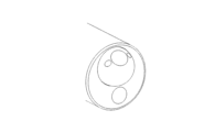
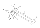
図8A~図8Fは、内視鏡デバイスの遠位先端10の様々な図を概略的に示している。この実施形態では、機械的装置は、カメラ12および照明源14、例えばLEDまたは光ファイバーの遠位端が装着される、ボール18を備える玉継手である。また、図には、作業チャネル16の遠位端が見えている。ボール18は、ケーブルまたは小型電動モータおよびギヤシステムを活性化させることによって、内視鏡デバイスのオペレータが回転させることができ、それによって、これらの図に見られるようにカメラの観察方向が変更される。
Figures 8A-8F schematically show various views of the
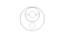
図9A~図9Cは、カメラ12および照明源14が装着された回転式カラー22を備える内視鏡デバイスの遠位先端10の様々な図を概略的に示している。また、遠位先端の遠位面にある第2のカメラ20および照明源14も図中に見られる。カメラ20は、固定された前方視の観察方向を有することができ、またはその観察方向を機械的装置によって変更することができる。内視鏡デバイスのオペレータは、カラーに接続されたケーブルを回転させることによって、または小型電動モータおよびギヤシステムを活性化させることによって、二重矢印24によって示される方向にカラー22を移動させ、それによって、図中に見られるようにカメラの観察方向を変更することができる。
9A-9C schematically show various views of the
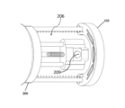
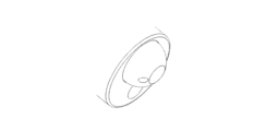
図10A~図12Cは、遠位先端のソケット30内の初期位置から、遠位先端からある距離だけ離れた位置まで位置を移動させることができる、カメラマウント26に装着されたカメラ12および照明源14を備える、内視鏡デバイスの遠位先端10の実施形態の様々な図を概略的に示している。またこれらの図全てにおいて、遠位先端にある第2のカメラ20、照明源14、および作業チャネル16も見えている。
10A-
図10Aは、本明細書で詳細に後述するメカニズムによって活性化されている、ロッド28によって支持されたカメラマウント26を示しており、カメラマウント26がソケット30から遠位先端10の前方の位置へと押し出されている。この実施形態では、カメラ14はカメラマウント26の前面に装着されて、前方視の観察方向が与えられている。図10Bは、ロッド28が遠位側に引っ張られてカメラマウント26をソケット30に引き込んでいる、図10Aの実施形態を示している。
FIG. 10A shows
図11A~図11Cは、カメラ12がカメラマウント26の底部に装着されていること(図11Bを参照)を除いて、図10Aおよび図10Bに示されるものと本質的に同じである、一実施形態を概略的に示している。この実施形態では、カメラ12および20の視野は、遠位先端の前方で互いに重なり合っている。これにより、遠位先端の前方に位置する物体を異なる観察方向から撮像することが可能になる。
11A-11C are essentially the same as those shown in FIGS. 10A and 10B, except that the
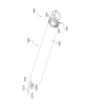
図12A~図12Cでは、ロッド32は、上述の図のロッド28のように直線ではない。ロッド32は、形状記憶材料から作ることができ、または関節部分を備えることができる。これにより、カメラ12を遠位先端から離すことが可能になり、また観察方向を、内視鏡デバイスの挿入チューブの長手方向軸線と比較して軸外にすることが可能になる。
12A-12C,
本明細書に記載する本発明の実施形態は単に例示のためのものである。本発明を実現する他の多くの手法が可能である。例えば、内視鏡デバイスは、内視鏡の遠位先端または挿入チューブに固定的に取り付けられた少なくとも1つのカメラと、内視鏡に固定的に取り付けられたカメラによって得ることができない視野を提供するために、内視鏡デバイスの表面に対して任意の方向に可逆的に延長されるように構成された1つまたは複数のロッドによって、内視鏡の遠位先端または挿入チューブに取り付けられた少なくとも1つのカメラと、を備えてもよい。別の例では、カメラのうちの1つまたは複数、例えば必須ではないが、遠位先端に固定されたカメラ、または伸縮式の1つもしくは複数のロッドによって内視鏡に取り付けられたカメラのうちの1つは、様々な観察方向を提供するために、カメラをパン、チルト、または回転させることができるような手法で装着されてもよい。他の例では、本明細書に記載する構成要素の異なる置換を利用することができ、例えば、図10A~図12Cの可動式カメラ12または固定された第2のカメラ20を、図8A~図8Fのように玉継手に装着されたカメラと入れ替えることができる。
The embodiments of the invention described herein are for illustration only. Many other ways of implementing the invention are possible. For example, an endoscopic device provides at least one camera fixedly attached to the distal tip or insertion tube of an endoscope and a field of view not available with a camera fixedly attached to the endoscope. attached to the distal tip of the endoscope or insertion tube by one or more rods configured to reversibly extend in any direction relative to the surface of the endoscopic device to at least one camera; In another example, one or more of the cameras, such as, but not necessarily, a camera fixed to the distal tip or attached to the endoscope by a telescoping rod or rods. may be mounted in such a way that the camera can be panned, tilted, or rotated to provide various viewing directions. In other examples, different permutations of the components described herein can be utilized, for example, the
本発明の実施形態は、内視鏡デバイスであり、内視鏡デバイスの遠位先端または挿入チューブに固定的に取り付けられた1つもしくは複数のカメラを備える第1のセットのカメラと、内視鏡デバイスの遠位先端または挿入チューブから外側へと可逆的に延長されるように構成された、1つもしくは複数のロッドにそれぞれ装着された第2のセットのカメラとで構成された可視化手段を備え、第1のセットのカメラは、内視鏡デバイスの内部から外側を見る視野を提供し、第2のセットのカメラは、内視鏡デバイスに向かって内側を見る視野を提供する。 An embodiment of the present invention is an endoscopic device comprising one or more cameras fixedly attached to the distal tip or insertion tube of the endoscopic device; a second set of cameras each mounted on one or more rods configured to reversibly extend outwardly from the distal tip of the speculum device or insertion tube. A first set of cameras provides a view looking outward from within the endoscopic device and a second set of cameras provides a view looking inward toward the endoscopic device.
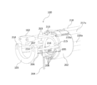
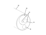
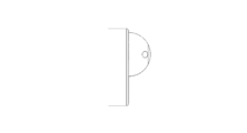
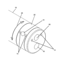
図1は、本発明による、可視化手段を備える内視鏡100の一実施形態の正面図を概略的に示している。図1は、内視鏡100の遠位面の中心にある、前方に面するカメラ101の位置と、この実施形態では光輪104である照明源とを示している。他の実施形態では、照明源は、当該分野で知られている他の任意のタイプのもの、例えばLEDまたは光ファイバーであることができる。内視鏡はまた、図を単純にするために遠位先端に示されていない、作業チャネル、および洗浄またはガス注入用のチャネルなど、他の従来の構成要素を備えてもよい。カメラマウント102は遠位先端の頂部に配置される。カメラマウント102は、後方に面するカメラ(図2Bに図示)と照明源(図には図示なし)とを備える。遠位先端100の下側にはステープラアンビル103が見えている。
Figure 1 schematically shows a front view of an embodiment of an
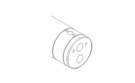
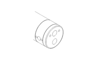
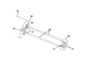
図2Aおよび図2Bは、開放構成にある内視鏡100の遠位端の概略斜視図である。図2Aおよび図2Bには、図には図示しない照明源とともにカメラマウント102に装着される、後方に面する第2のカメラ(図2Bの209)が見えている。この実施形態では、カメラマウント102は、基部202に当接する第1の位置から、基部202から離隔された第2の位置へと遠位側に延長させ、第2の位置から近位側に後退させて第1の位置に戻すことができる、2つのロッド203に取り付けられる。
2A and 2B are schematic perspective views of the distal end of
本発明の一実施形態では、基部202は、専用の内視鏡の一体部品である、特別に構成された遠位先端である。この実施形態では、遠位先端は2つのボアを備え、それらを通してロッド203を遠位側および近位側に摺動させることができる。本発明の別の実施形態では、基部202は、標準的な内視鏡の遠位先端の上を滑動するとともに遠位先端に取り付けられるカラーである。この実施形態では、カラーは2つのボアを備え、それらを通してロッド203を遠位側および近位側に摺動させることができる。この追加の実施形態では、本明細書で後述するように、ロッドおよび電線をカメラマウント102上のカメラおよび照明手段まで移動させる操作ワイヤと、内視鏡の挿入チューブの外部に配置される信号線とを被覆するのに、エラストマー性のシース(図7を参照)が使用される。
In one embodiment of the invention,
伸縮式カメラロッド203は、カメラマウント102を基部202から離すように遠位側に、またそれに向かって近位側に移動させるように構成される。カメラロッド203の運動は、ロッド203の近位端に取り付けられた、ケーブル、ロッド、または他の機械的手段(図示なし)によって制御される。単純にするため、ロッドを横方向に移動させる当該分野で知られている任意の装置を、以下、ワイヤと呼ぶ。ワイヤは、ワイヤが遠位側に押されたときにカメラロッド203を遠位側に移動させるのに十分な固さのものである。基部202が内視鏡の一体部品である実施形態では、ワイヤは、内視鏡の挿入チューブのチャネルを貫通してハンドルまで至り、そこでワイヤの近位端が、カメラロッド203を延長し後退させるように構成されたメカニズムに取り付けられる。基部202が内視鏡上に追加される実施形態では、ワイヤは、シースによって内視鏡の挿入軸に接して保持されたチューブ217aおよび217bを貫通し、内視鏡の近位端に配置された専用の制御ボックスまで至る。
Telescoping
アンビル103およびステープルカートリッジ205で構成されたステープル留めデバイスは、基部202上に配置される。カートリッジ205およびアンビル103の設計は、本特許出願の出願人に対するWO2007/141776に既に記載されている。アンビル103は、遠位側に延長させて開放構成(図2Aに図示)を得ることができる、または近位側に後退させて閉止構成(図1に図示)を得ることができる、伸縮式ロッド207に装着される。ロッド207の運動は、ロッド203に関して本明細書で上述したものと類似の、機械式、空圧式、または油圧式装置によって制御される。基部202が内視鏡の一体部品である実施形態では、ロッド207の移動を制御するワイヤは、内視鏡の挿入チューブのチャネルを貫通してハンドルまで至り、そこでワイヤの近位端が、ロッド207を延長し後退させるように構成されたメカニズムに取り付けられる。基部202が内視鏡に追加される実施形態では、ワイヤは、追加のシースによって封止されたチューブ220aおよび220bを貫通する。アンビル103を後退させると、即ちロッド207を近位側に移動させると、基部202に固定的に取り付けられた位置合わせピン215がアンビル103の位置合わせ開口部214に入って、アンビルがカートリッジ205と完璧に位置合わせされる。他の実施形態では、超音波または光センサシステムなどの装置を、位置合わせピン215および開口部214の代わりに使用して、アンビルとカートリッジとの位置合わせを得て検証することができる。
A stapling device consisting of
ステープラのこの設計では、ステープラカートリッジ205は、医療用ステープラで従来見出されるものなど、ステープルを動的に排出するカムの装置は備えていない。本発明のステープル留めデバイスでは、本明細書で上述したようにアンビル103を近位側に後退させると、アンビル103の面が、アンビルとカートリッジ300との間にある組織の部分を係合し、その組織の部分をカートリッジ300の遠位面に押し付け、アンビル103を継続して後退させると、カートリッジ205の遠位部分が近位側へと摺動して近位部分に入る。ステープルプッシャもステープルも近位部分の内部では移動せず、ステープルの脚が、カートリッジ205の遠位端にあるスロット208を通ってカートリッジ205の遠位部分から受動的に押し出され、アンビル103の面にある一致する窪み210を係合する。アンビル103の伸縮式ロッド207に取り付けられたワイヤを引っ張り続けることで、ステープルの脚が窪み210の中で丸まり始めるまで、ステープルの脚の長さが次第にスロット208および組織層を通って外に出る。プロセスは、ステープルがカートリッジ205を完全に出て、脚が完全に丸まり、組織層をともにステープル留めするプロセスが完了するまで続く。
In this design of the stapler, the
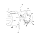
少なくとも1つの組織把持具204を備える組織把持デバイスは、基部202から可逆的に延長されるように構成される。図2Aおよび図2Bに示される実施形態では、把持具204は固いワイヤで作られ、その遠位端はらせん形状に曲げられる。把持手段の他の実施形態は、例えば、鉗子または当該分野で知られている任意の類似の把持器具を含むことができる。把持具204の近位端はワイヤ216に接続され、ワイヤは、内視鏡のハンドル内の、または把持具204の長手方向運動および回転運動を制御する専用の制御ボックス内のメカニズムに接続される。基部202が内視鏡の一体部品である実施形態では、ワイヤ216は内視鏡の挿入チューブ内のチャネルを貫通し、基部202が内視鏡上に追加される実施形態では、ワイヤ216はチューブ218を貫通して内視鏡100の近位端に至る。
A tissue grasping device comprising at least one
図2Aおよび図2Bに示される開放構成では、2本の破線間のギャップとして示される操作空間206が、ロッド207間、およびカートリッジ205とアンビル103との間の空間内に存在する。操作空間206内で、穴の閉鎖またはポリープ除去などの医療処置を行うことができる。ワイヤ216を遠位側に延長させ回転させると、内視鏡100の遠位面の前方に位置する組織(図示なし)に貫入し把持するために、把持具204がらせん運動で前進させられる。組織のしっかりした把持が達成されると、把持具204を後退させ、それによって組織が操作空間206内へと上方かつ後方に引っ張られる。
In the open configuration shown in FIGS. 2A and 2B, an
後方に面するカメラ209によって、前方視のカメラ101によって得られない視点からだけではなく、前方に面するカメラ101の視野が操作空間206内に位置する組織によって完全に遮断されているとき、例えば、端部を互いにステープル留めし、穴を閉鎖するために、穴を取り囲む組織が把持具204によって引き上げられているときも、操作空間206内で実施される処置の継続的な観察が可能になる。
With the rear-facing
図3および図4はそれぞれ、開放構成にある内視鏡100の側面図および下面図を示している。図3では、把持具204は、操作空間206を通って延長されて示されている。図4は、後方に面するカメラ209と操作空間206との間の明確な見通し線を示している。本明細書では1つの把持具のみが例示されているが、組織を掴んで操作空間206に引き込む、2つ以上の把持具を有するECDの実施形態を提供できることが注目される。
3 and 4 show side and bottom views, respectively, of
図5は、内視鏡100の追加の実施形態を概略的に示している。チューブ217a、217b、218、220a、および220bは、シース810の近位端に示されている。把持具204を制御するのに使用されるワイヤ216(図5には図示なし)は、チューブ218を貫通する。同様に、ロッド207の長手方向運動を制御するワイヤが、チューブ220aおよび220bを貫通する。ロッド203の長手方向運動を制御するワイヤは、チューブ217aおよび217bを貫通する。
FIG. 5 schematically illustrates an additional embodiment of
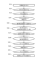
図6Aは、本明細書で上述した内視鏡クロージャデバイス(ECD)の実施形態を使用する、内視鏡クロージャプロセスを説明するフローチャートである。最初のステップ501で、内視鏡100が患者の体内に挿入され、前方に面するカメラ101を使用して、挿入チューブが閉鎖すべき組織の穴の位置へと案内され、ステップ502で、遠位先端が閉鎖すべき穴の上方で穴に対して平行に位置決めされる。ステップ503で、オペレータがワイヤを作動させて、アンビル103およびカメラマウント102を遠位側に移動させることによって、操作空間206が作られる。ステップ504で、オペレータがワイヤ216を作動させて、把持具204を操作空間206を通して延長させ、関心の組織を把持するために回転させる。把持具204が穴の周りの組織をしっかり掴むと、ステップ505で、把持具204および付随する組織が操作空間を通して上方かつ近位側に引っ張られて、閉鎖すべき穴全体がカートリッジ205の遠位端にあるスロット208の上方に来るまで、関心の組織が操作空間を通して引っ張られる。ステップ506で、後方に面するカメラ209を使用して、組織がステープルカートリッジに対して適正位置にあることが確保される。ステップ507で、アンビルをカートリッジに向かって後退させて、組織がアンビルとカートリッジとの間で圧迫される。ステップ508で、本明細書で上述したように、ステープル列がカートリッジから組織を通して排出される。ステップ509で、アンビルを遠位側に移動させて、ステープル留めされた組織が操作空間から解放され、その後、後方に面するカメラ209を使用して、ステープル留め処置が適切に実行されたことが検査され確認される。最後に、ステップ510で、内視鏡100が患者の身体から撤回される。
FIG. 6A is a flow chart describing the endoscope closure process using the embodiments of the endoscope closure device (ECD) described herein above. In a
図6Aのステップの順序は単に例示のために与えられるものである。ステップの他の順序が可能であり、例えば、ステップ502および503を入れ替えて、ECDを穴に対して位置決めする助けとするのに後方に面するカメラを使用するのを可能にすることができる。 The order of steps in FIG. 6A is provided for illustration purposes only. Other sequences of steps are possible, for example, steps 502 and 503 can be interchanged to allow a rear-facing camera to be used to help position the ECD with respect to the hole.
別の実施形態によれば、内視鏡100は、組織を切り取るように適合された切断デバイス、例えばブレードまたは加熱したワイヤを備え、それにより、組織閉鎖を実施することに加えて、組織、例えばポリープを除去することを可能にする。異なる実施形態では、切断デバイスは、アンビルの近位面に装着されるか、カートリッジの遠位面に装着されるか、または内視鏡の作業チャネルを貫通させる別個の器具として実現される。
According to another embodiment,
図6Bは、ポリープまたは腫瘍などの成長部を除去する全層切除(FTR)処置を実施する、内視鏡100の使用を説明するフローチャートである。この図では、内視鏡デバイス100は全層切除デバイス(FTRD)として知られている。最初のステップ511で、内視鏡100が患者の体内に挿入され、前方に面するカメラ101の助けによって、除去すべき成長部の位置へと案内され、ステップ512で、成長部の上方で成長部に対して平行に位置決めされる。ステップ513で、オペレータがワイヤを作動させて、アンビルおよびカメラマウントを遠位側に移動させることによって、操作空間206が作られる。ステップ514で、前方に面するカメラおよび後方に面するカメラの両方を使用して、成長部が操作空間の下方にあるように、内視鏡の位置が調節される。ステップ515で、オペレータがワイヤを作動させて、把持具204を操作空間206を通して延長させ、成長部を把持するために回転させる。把持具204が成長部をしっかり把持した後、ステップ516で、把持具を操作空間を通して後退させて、成長部全体がステープルカートリッジの上方に来て、成長部の下方にある組織の部分がカートリッジ205の遠位端にあるスロット208に対向して配置されるまで、成長部が操作空間を通して引っ張られる。処置のこの時点で、前方に面するカメラ101の視野は成長部によって遮断されるので、次のステップ517で、後方に面するカメラ209を使用して、成長部が適正位置にあることが確保される。ステップ518で、アンビルをカートリッジに向かって後退させて、成長部の下方にある組織がアンビルとカートリッジとの間で圧迫される。ステップ519で、少なくとも1つのステープルが、カートリッジから成長部の下方にある組織を通して排出される。ステップ520で、切断デバイスをオペレータが作動させ、成長部の下方にある組織がステープルラインの上方で切断される。次のステップ521で、アンビルを遠位側に移動させて、ステープル留めされた組織が操作空間から解放され、成長部は把持具に接続されたままにされる。次の最終ステップ522で、成長部が内視鏡100とともに患者の身体から撤回される。
FIG. 6B is a flow chart describing the use of
追加のステップをステップ519と520との間に導入することができる。この追加のステップは、ステープルを発射した後にアンビルを遠位側に移動させて、後方に面するカメラ209を使用して、ステープル留めされた組織の詳細な検査を実施し、続いてアンビルを近位側に移動させてから組織を切断することを含む。
Additional steps can be introduced between
図6Bに示されるステップの順序は単に例示のために提示されるものである。ステップの他の順序が可能であり、例えば、ステップ512および513を入れ替えて、内視鏡を成長部に対して位置決めする助けとするのに後方に面するカメラを使用するのを可能にすることができる。
The order of steps shown in FIG. 6B is presented for illustration purposes only. Other sequences of steps are possible, for example, interchanging
本明細書で上述した内視鏡100の実施形態では、図6Aおよび図6Bに記載したものなどの処置を実施するために、伸縮式アンビルロッド207の間に固定の距離があり、そこを通して成長部および組織を引っ張ることができる。この距離は、内視鏡100の挿入軸の最大径によって決定され、その最大径は、処置が実施されるべき部位に達するために挿入軸が通らなければならない管腔の最小内径によって決定される。したがって、場合によっては、ロッド207間の開口部よりも大きい直径を有する成長部または穴は、ロッド間の操作空間に全体を引き込むことができないので、うまく操作することができない。
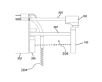
In the embodiments of
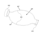
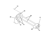
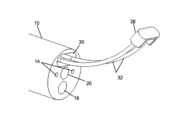
図7(図面の2/11ページを参照)は、ロッド間の限定された距離の問題に対する解決策を提供するように構成されたロッド401によって、基部202に取り付けられたアンビル103の斜視図である。本明細書で上述したロッド207の場合のように、ロッド401の近位端は、内視鏡のハンドルまたは専用ボックスから遠位側および近位側へのアンビルの移動を制御する、ワイヤの遠位端に接続される。これらのワイヤは、内視鏡100の挿入チューブの内部にあるチューブを貫通するか、または追加の実施形態におけるチューブ220aおよび220bを貫通する。ワイヤが近位側に引っ張られると、ロッド401は、直線構成のチューブ内部で拘束された第1の位置にある。ワイヤが遠位側に引っ張られ、チューブを出るにつれて、それらのプレ形状記憶特性によって、基部202の前方で完全に延長されたとき、図7に示される形状を有する第2の位置に達するまで外側に曲がる。
FIG. 7 (see page 2/11 of the drawings) is a perspective view of
ECD100を関心の組織の上方で位置決めし、ロッド401を延長した後、組織は把持具204によって掴まれ、操作空間206に引き込まれる。組織が掴まれ操作空間に引き込まれた後、ロッド401が近位側に後退させられて、チューブ220aおよび220bに引き込まれる。ロッド401がチューブに入ると、ロッドは真っ直ぐにされ、上述したように、組織がステープル留めのためにカートリッジ205とアンビル103との間で最終的に圧迫されるまで、ロッド401が包囲している組織がロッドの間で圧縮される。
After positioning
本発明の実施形態を例示として記載してきたが、本発明は、特許請求の範囲を超えることなく、多くの変形、修正、および適応を含めて実施されてもよいことが理解されるであろう。 Although embodiments of the invention have been described by way of example, it will be appreciated that the invention may be practiced with many variations, modifications and adaptations without exceeding the scope of the claims. .
Claims (13)
(a)前記少なくとも1つのカメラを前記初期位置から、前記遠位先端または前記挿入チューブの上の、中の、もしくはそこから離隔された、1つまたは複数の異なる位置へと移動させること、ならびに
(b)前記少なくとも1つのカメラの観察方向を変更すること、のうちの少なくとも1つを行うように構成されることを特徴とする、内視鏡デバイス。 An endoscopic device comprising an insertion tube, a distal tip, and at least one camera positioned at an initial position on or in said distal tip or said insertion tube, said endoscopic device comprising: a mechanical device activated from the proximal end, the mechanical device comprising:
(a) moving the at least one camera from the initial position to one or more different positions on, in, or spaced from the distal tip or the insertion tube; and (b) changing the viewing direction of the at least one camera.
a)専用の内視鏡の一体部品であり、前記少なくとも1つのロッドを中を通して遠位側および近位側に摺動させることができる少なくとも1つのボアを備える、特別に構成された遠位先端、ならびに
b)内視鏡の前記遠位先端の上を滑動する、前記遠位先端に取り付けられたカラーであって、前記少なくとも1つのロッドを中を通して遠位側および近位側に摺動させることができる少なくとも1つのボアを備える、カラー、のうちの1つである、請求項5に記載の内視鏡デバイス。 The base is
a) a specially configured distal tip that is an integral part of a dedicated endoscope and includes at least one bore through which said at least one rod can be slid distally and proximally; and b) a collar attached to said distal tip that slides over said distal tip of an endoscope, sliding said at least one rod distally and proximally therethrough. 6. The endoscopic device of claim 5, wherein the collar comprises at least one bore capable of
a)請求項8に記載の内視鏡デバイスを患者の体内に挿入し、前記前方に面するカメラを使用して、患者の組織にある閉鎖すべき穴の位置へと前記挿入チューブを案内するステップと、
b)前記前方に面するカメラを使用して、前記内視鏡デバイスの前記遠位先端を閉鎖すべき前記穴の上方で前記穴に対して平行に位置決めするステップと、
c)ワイヤを作動させることで、前記ステープル留めデバイスの前記アンビルおよび前記カメラマウントを遠位側に移動させるステップと、
d)前記少なくとも1つの組織把持具を作動させて延長させ、前記穴の周りの組織をしっかり掴ませるステップと、
e)閉鎖すべき前記穴を取り囲む組織が全て、前記ステープルカートリッジの前記近位部分に格納されたステープルがそこを通って前記ステープルカートリッジの前記遠位部分から排出されるスロットの上方に来るまで、前記組織把持具および付随する組織を上方かつ近位側に引っ張るステップと、
f)前記後方に面するカメラを使用して、前記組織が前記ステープルカートリッジに対して適正に位置決めされていることを確保するステップと、
g)前記アンビルを前記ステープルカートリッジに向かって後退させることによって、前記穴を取り囲む前記組織を前記アンビルと前記ステープルカートリッジとの間で圧迫するステップと、
h)前記アンビルを前記ステープルカートリッジに向かって後退させ続けることによって、ステープル列を前記ステープルカートリッジから前記組織を通して排出するステップと、
i)前記アンビルを遠位側に移動させることによって、ステープル留めされた前記組織を解放し、前記後方に面するカメラを使用して、ステープル留め処置が適切に実行されたことを検査し確認するステップと、
j)前記内視鏡を前記患者の身体から撤回するステップと、を含む方法。 A method of performing an endoscopic closure procedure using the endoscopic device of claim 8, comprising:
a) inserting the endoscopic device of claim 8 into a patient and using the forward-facing camera to guide the insertion tube to the location of the hole in the patient's tissue to be closed; a step;
b) using the forward-facing camera to position the distal tip of the endoscopic device above and parallel to the hole to be closed;
c) actuating a wire to move the anvil and camera mount of the stapling device distally;
d) actuating and extending the at least one tissue grasper to grip tissue around the hole;
e) until all tissue surrounding the hole to be closed is over slots through which staples stored in the proximal portion of the staple cartridge exit from the distal portion of the staple cartridge; pulling the tissue grasper and associated tissue upward and proximal;
f) using the rear-facing camera to ensure that the tissue is properly positioned relative to the staple cartridge;
g) compressing the tissue surrounding the hole between the anvil and the staple cartridge by retracting the anvil toward the staple cartridge;
h) ejecting a row of staples from the staple cartridge through the tissue by continuing to retract the anvil toward the staple cartridge;
i) release the stapled tissue by moving the anvil distally and use the rear-facing camera to inspect and confirm that the stapling procedure was performed properly; a step;
j) withdrawing said endoscope from said patient's body.
a)請求項9または10に記載の内視鏡を患者の体内に挿入し、前記前方に面するカメラを使用して、除去すべき成長部の位置へと前記内視鏡を案内するステップと、
b)前記前方に面するカメラを使用して、前記内視鏡を前記成長部の上方で前記成長部に対して平行に位置決めするステップと、
c)ワイヤを作動させることで、前記アンビルおよび前記カメラマウントを遠位側に移動させるステップと、
d)前記前方に面するカメラおよび前記後方に面するカメラの両方を使用して、前記成長部が前記内視鏡の前記遠位先端の下方かつ前方に適正に位置決めされるように、前記内視鏡の位置を調節するステップと、
e)前記組織把持具を作動させて前記成長部をしっかり把持するステップと、
f)前記把持具を後退させることによって、前記成長部を取り囲む組織の部分が、前記ステープルカートリッジの前記近位部分にあるステープルが前記ステープルカートリッジの前記遠位部分から排出される際に通るスロットに対向して配置されるまで、前記成長部全体を前記ステープルカートリッジの上方へと引っ張るステップと、
g)前記後方に面するカメラを使用して、前記成長部が適正位置にあることを確保するステップと、
h)前記アンビルを前記ステープルカートリッジに向かって後退させることによって、前記成長部を取り囲む組織を前記アンビルと前記ステープルカートリッジとの間で圧迫するステップと、
i)前記アンビルを前記ステープルカートリッジに向かって後退させ続けることによって、少なくとも1つのステープルを前記ステープルカートリッジから前記成長部を取り囲む前記組織を通して排出するステップと、
j)前記切断デバイスを作動させることによって、前記成長部を取り囲む前記組織をステープルラインの下方で切断するステップと、
k)前記アンビルを遠位側に移動させることによって、前記成長部が前記把持具に接続されたままの状態で、ステープル留めされた前記組織を解放するステップと、
l)前記成長部を前記内視鏡とともに前記患者の身体から撤回するステップと、を含む方法。 11. A method of performing a full thickness resection (FTR) procedure to remove growths using the endoscopic device of claim 9 or 10, comprising:
a) inserting an endoscope according to claim 9 or 10 into a patient's body and using said forward-facing camera to guide said endoscope to the location of a growth to be removed; ,
b) positioning the endoscope over and parallel to the outgrowth using the forward-facing camera;
c) actuating a wire to move the anvil and camera mount distally;
d) using both the forward-facing camera and the rearward-facing camera to position the in-growth properly below and forward of the distal tip of the endoscope; adjusting the position of the scope;
e) actuating the tissue grasper to firmly grasp the growth;
f) retracting the grasper causes the portion of the tissue surrounding the growth to enter the slot through which staples in the proximal portion of the staple cartridge are ejected from the distal portion of the staple cartridge; pulling the entire outgrowth up the staple cartridge until it is positioned oppositely;
g) using the rear-facing camera to ensure that the growth is in place;
h) compressing tissue surrounding the growth between the anvil and the staple cartridge by retracting the anvil toward the staple cartridge;
i) ejecting at least one staple from the staple cartridge through the tissue surrounding the growth by continuing to retract the anvil toward the staple cartridge;
j) severing the tissue surrounding the growth below the staple line by actuating the cutting device;
k) releasing the stapled tissue while the outgrowth remains connected to the grasper by moving the anvil distally;
l) withdrawing the outgrowth from the patient's body together with the endoscope.
Applications Claiming Priority (3)
| Application Number | Priority Date | Filing Date | Title |
|---|---|---|---|
| US202062988466P | 2020-03-12 | 2020-03-12 | |
| US62/988,466 | 2020-03-12 | ||
| PCT/IL2021/050245 WO2021181376A1 (en) | 2020-03-12 | 2021-03-07 | Endoscope devices comprising a moveable camera |
Publications (1)
| Publication Number | Publication Date |
|---|---|
| JP2023517618A true JP2023517618A (en) | 2023-04-26 |
Family
ID=77671342
Family Applications (1)
| Application Number | Title | Priority Date | Filing Date |
|---|---|---|---|
| JP2022554642A Pending JP2023517618A (en) | 2020-03-12 | 2021-03-07 | Endoscope device with movable camera |
Country Status (6)
| Country | Link |
|---|---|
| US (1) | US20230000328A1 (en) |
| EP (1) | EP4117502A4 (en) |
| JP (1) | JP2023517618A (en) |
| KR (1) | KR20230002380A (en) |
| CN (1) | CN115279246A (en) |
| WO (1) | WO2021181376A1 (en) |
Families Citing this family (9)
| Publication number | Priority date | Publication date | Assignee | Title |
|---|---|---|---|---|
| US20230000495A1 (en) * | 2021-06-30 | 2023-01-05 | Covidien Lp | Circular stapling device with tissue grasping members |
| US12586226B2 (en) | 2021-07-13 | 2026-03-24 | General Electric Company | Method for inspecting an object |
| US12602808B2 (en) | 2021-07-13 | 2026-04-14 | General Electric Company | Method for inspecting an object |
| US12610116B2 (en) * | 2022-11-11 | 2026-04-21 | General Electric Company | Inspection systems and methods employing directional light for enhanced imaging |
| US12596076B2 (en) | 2022-11-11 | 2026-04-07 | General Electric Company | Inspection systems and methods employing different wavelength directional light for enhanced imaging |
| US12495214B2 (en) | 2023-03-15 | 2025-12-09 | General Electric Company | Pulse illumination imaging of a target element |
| DE102023126150A1 (en) * | 2023-09-26 | 2025-03-27 | Karl Storz Se & Co. Kg | Resectoscope device, resectoscope, resection system and imaging procedure |
| US12593131B2 (en) | 2023-09-05 | 2026-03-31 | General Electric Company | Velocity matching imaging of a target element |
| CN117204944A (en) * | 2023-11-07 | 2023-12-12 | 上海宇度医学科技股份有限公司 | An endoscope with an electric cutter |
Family Cites Families (9)
| Publication number | Priority date | Publication date | Assignee | Title |
|---|---|---|---|---|
| US6277064B1 (en) * | 1997-12-30 | 2001-08-21 | Inbae Yoon | Surgical instrument with rotatably mounted offset endoscope |
| US6478210B2 (en) * | 2000-10-25 | 2002-11-12 | Scimed Life Systems, Inc. | Method and device for full thickness resectioning of an organ |
| JP5435957B2 (en) * | 2006-01-23 | 2014-03-05 | アヴァンティス メディカル システムズ インコーポレイテッド | Endoscope |
| IL176133A0 (en) * | 2006-06-05 | 2006-10-05 | Medigus Ltd | Stapler |
| KR101150350B1 (en) * | 2011-12-26 | 2012-06-08 | 윤치순 | 3-dimensional endoscopic surgery apparratus |
| US20130284792A1 (en) * | 2012-04-26 | 2013-10-31 | Covidien Lp | Surgical Stapling Device Including A Camera |
| US9986899B2 (en) * | 2013-03-28 | 2018-06-05 | Endochoice, Inc. | Manifold for a multiple viewing elements endoscope |
| US20190082940A1 (en) * | 2013-08-31 | 2019-03-21 | Morena Medical Applications Ltd. | Endoscope with shared working channel |
| JP6930062B2 (en) * | 2015-05-12 | 2021-09-01 | レビー、エイブラハム | Dynamic field endoscope |
-
2021
- 2021-03-07 JP JP2022554642A patent/JP2023517618A/en active Pending
- 2021-03-07 EP EP21768612.0A patent/EP4117502A4/en not_active Withdrawn
- 2021-03-07 KR KR1020227035049A patent/KR20230002380A/en not_active Withdrawn
- 2021-03-07 WO PCT/IL2021/050245 patent/WO2021181376A1/en not_active Ceased
- 2021-03-07 CN CN202180020613.XA patent/CN115279246A/en active Pending
-
2022
- 2022-09-08 US US17/930,495 patent/US20230000328A1/en not_active Abandoned
Also Published As
| Publication number | Publication date |
|---|---|
| WO2021181376A1 (en) | 2021-09-16 |
| EP4117502A4 (en) | 2024-03-13 |
| EP4117502A1 (en) | 2023-01-18 |
| US20230000328A1 (en) | 2023-01-05 |
| CN115279246A (en) | 2022-11-01 |
| KR20230002380A (en) | 2023-01-05 |
Similar Documents
| Publication | Publication Date | Title |
|---|---|---|
| JP2023517618A (en) | Endoscope device with movable camera | |
| JP5407036B2 (en) | Treatment endoscope | |
| US10292693B2 (en) | Devices for introducing multiple instruments and methods of use | |
| US9649015B2 (en) | Treatment tool for endoscope | |
| CN101489491B (en) | Deployment system for introducing surgical instruments into a patient | |
| US8480700B2 (en) | Full thickness resection device | |
| JP7518252B2 (en) | Apparatus and method for retracting tissue | |
| JP6427109B2 (en) | Bending treatment tool | |
| JP2014519873A (en) | device | |
| US20250352204A1 (en) | Stapler apparatus and methods for use | |
| US20210093163A1 (en) | Endoscope with integrated tissue acquisition capability | |
| US12376880B2 (en) | Medical systems, devices, and related methods | |
| US20240050319A1 (en) | Medical device with integrated instrument and related methods | |
| JP7798980B2 (en) | Endoscopic tool stabilization and related methods of use | |
| US20230056943A1 (en) | Stapler apparatus and methods for use | |
| US9549661B2 (en) | Medical device actuation systems and related methods of use | |
| KR101750628B1 (en) | An apparatus for surgery comprising a surgical arm attached to the endoscope and a surgery system comprising thereof | |
| US20220095888A1 (en) | Medical systems, devices, and related methods | |
| US20210068637A1 (en) | Endoscope and channel tube | |
| KR102172603B1 (en) | Endoscopic instrument and polyp retrieving instrument of attached to endoscopic instrument | |
| JP2002282202A (en) | Intracavitary lighting device | |
| US20210059659A1 (en) | Devices and methods for closure of openings in tissue | |
| CN118119346A (en) | Scalable devices and systems |