JP2023183731A - Work machine - Google Patents
Work machine Download PDFInfo
- Publication number
- JP2023183731A JP2023183731A JP2022097397A JP2022097397A JP2023183731A JP 2023183731 A JP2023183731 A JP 2023183731A JP 2022097397 A JP2022097397 A JP 2022097397A JP 2022097397 A JP2022097397 A JP 2022097397A JP 2023183731 A JP2023183731 A JP 2023183731A
- Authority
- JP
- Japan
- Prior art keywords
- electric motor
- control unit
- trigger lever
- battery pack
- chainsaw
- Prior art date
- Legal status (The legal status is an assumption and is not a legal conclusion. Google has not performed a legal analysis and makes no representation as to the accuracy of the status listed.)
- Pending
Links
- 239000003921 oil Substances 0.000 claims description 48
- 230000005484 gravity Effects 0.000 claims description 39
- 230000005540 biological transmission Effects 0.000 claims description 26
- 239000007769 metal material Substances 0.000 claims description 23
- 239000010687 lubricating oil Substances 0.000 claims description 13
- 230000001050 lubricating effect Effects 0.000 claims description 4
- 238000005516 engineering process Methods 0.000 abstract description 2
- 239000000463 material Substances 0.000 description 23
- 238000001816 cooling Methods 0.000 description 19
- 230000000694 effects Effects 0.000 description 8
- 239000004952 Polyamide Substances 0.000 description 6
- 239000003638 chemical reducing agent Substances 0.000 description 6
- 229920001971 elastomer Polymers 0.000 description 6
- 210000003811 finger Anatomy 0.000 description 6
- 239000004033 plastic Substances 0.000 description 6
- 229920002647 polyamide Polymers 0.000 description 6
- 239000005060 rubber Substances 0.000 description 6
- 229920000459 Nitrile rubber Polymers 0.000 description 5
- XEEYBQQBJWHFJM-UHFFFAOYSA-N Iron Chemical compound [Fe] XEEYBQQBJWHFJM-UHFFFAOYSA-N 0.000 description 4
- HBBGRARXTFLTSG-UHFFFAOYSA-N Lithium ion Chemical compound [Li+] HBBGRARXTFLTSG-UHFFFAOYSA-N 0.000 description 4
- 229910052782 aluminium Inorganic materials 0.000 description 4
- XAGFODPZIPBFFR-UHFFFAOYSA-N aluminium Chemical compound [Al] XAGFODPZIPBFFR-UHFFFAOYSA-N 0.000 description 4
- 210000000078 claw Anatomy 0.000 description 4
- 238000005520 cutting process Methods 0.000 description 4
- 239000000945 filler Substances 0.000 description 4
- 229910001416 lithium ion Inorganic materials 0.000 description 4
- 238000005452 bending Methods 0.000 description 2
- 229910052742 iron Inorganic materials 0.000 description 2
- 238000000034 method Methods 0.000 description 2
- 229920000181 Ethylene propylene rubber Polymers 0.000 description 1
- 238000010586 diagram Methods 0.000 description 1
- 230000005489 elastic deformation Effects 0.000 description 1
- 239000000446 fuel Substances 0.000 description 1
- 230000002093 peripheral effect Effects 0.000 description 1
- 239000004417 polycarbonate Substances 0.000 description 1
- 229920000515 polycarbonate Polymers 0.000 description 1
- 238000003825 pressing Methods 0.000 description 1
- 230000001681 protective effect Effects 0.000 description 1
- 238000013138 pruning Methods 0.000 description 1
- 210000003813 thumb Anatomy 0.000 description 1
- 239000002023 wood Substances 0.000 description 1
Images


Classifications
-
- B—PERFORMING OPERATIONS; TRANSPORTING
- B27—WORKING OR PRESERVING WOOD OR SIMILAR MATERIAL; NAILING OR STAPLING MACHINES IN GENERAL
- B27B—SAWS FOR WOOD OR SIMILAR MATERIAL; COMPONENTS OR ACCESSORIES THEREFOR
- B27B17/00—Chain saws; Equipment therefor
- B27B17/02—Chain saws equipped with guide bar
-
- B—PERFORMING OPERATIONS; TRANSPORTING
- B27—WORKING OR PRESERVING WOOD OR SIMILAR MATERIAL; NAILING OR STAPLING MACHINES IN GENERAL
- B27B—SAWS FOR WOOD OR SIMILAR MATERIAL; COMPONENTS OR ACCESSORIES THEREFOR
- B27B17/00—Chain saws; Equipment therefor
- B27B17/0008—Means for carrying the chain saw, e.g. handles
-
- A—HUMAN NECESSITIES
- A01—AGRICULTURE; FORESTRY; ANIMAL HUSBANDRY; HUNTING; TRAPPING; FISHING
- A01G—HORTICULTURE; CULTIVATION OF VEGETABLES, FLOWERS, RICE, FRUIT, VINES, HOPS OR SEAWEED; FORESTRY; WATERING
- A01G3/00—Cutting implements specially adapted for horticultural purposes; Delimbing standing trees
- A01G3/08—Other tools for pruning, branching or delimbing standing trees
- A01G3/085—Motor-driven saws for pruning or branching
- A01G3/086—Chain saws
-
- B—PERFORMING OPERATIONS; TRANSPORTING
- B25—HAND TOOLS; PORTABLE POWER-DRIVEN TOOLS; MANIPULATORS
- B25F—COMBINATION OR MULTI-PURPOSE TOOLS NOT OTHERWISE PROVIDED FOR; DETAILS OR COMPONENTS OF PORTABLE POWER-DRIVEN TOOLS NOT PARTICULARLY RELATED TO THE OPERATIONS PERFORMED AND NOT OTHERWISE PROVIDED FOR
- B25F5/00—Details or components of portable power-driven tools not particularly related to the operations performed and not otherwise provided for
- B25F5/02—Construction of casings, bodies or handles
-
- B—PERFORMING OPERATIONS; TRANSPORTING
- B27—WORKING OR PRESERVING WOOD OR SIMILAR MATERIAL; NAILING OR STAPLING MACHINES IN GENERAL
- B27B—SAWS FOR WOOD OR SIMILAR MATERIAL; COMPONENTS OR ACCESSORIES THEREFOR
- B27B17/00—Chain saws; Equipment therefor
- B27B17/12—Lubricating devices specially designed for chain saws
-
- B—PERFORMING OPERATIONS; TRANSPORTING
- B27—WORKING OR PRESERVING WOOD OR SIMILAR MATERIAL; NAILING OR STAPLING MACHINES IN GENERAL
- B27B—SAWS FOR WOOD OR SIMILAR MATERIAL; COMPONENTS OR ACCESSORIES THEREFOR
- B27B17/00—Chain saws; Equipment therefor
- B27B17/08—Drives or gearings; Devices for swivelling or tilting the chain saw
- B27B17/086—Angle drives
Abstract
Description
本明細書で開示する技術は、作業機に関する。 The technology disclosed herein relates to a work machine.
特許文献1には、前後方向に長手方向を有する作業部と、前記作業部を駆動する電動モータと、前記電動モータを制御する制御ユニットと、前記作業部の後方で前記作業部を保持するとともに、前記電動モータおよび前記制御ユニットを収容するハウジング本体と、前記ハウジング本体から延びており、ユーザの一方の手によって把持されるグリップと、を含むハウジングと、前記ハウジングに取り付けられ、前記制御ユニットを介して前記電動モータに電力を供給可能な電池パックと、前記グリップに設けられており、ユーザの手指で前記グリップ側に引かれることによって、前記電動モータを作動するトリガレバーと、を備える作業機が開示されている。前記制御ユニットの前端は、前記トリガレバーの前端よりも前方に配置されている。 Patent Document 1 discloses a working part having a longitudinal direction in the front-rear direction, an electric motor that drives the working part, a control unit that controls the electric motor, and a control unit that holds the working part behind the working part. , a housing including a housing body housing the electric motor and the control unit; and a grip extending from the housing body and gripped by one hand of a user; A work machine comprising: a battery pack capable of supplying power to the electric motor through the battery pack; and a trigger lever provided on the grip and actuating the electric motor when pulled toward the grip by a user's finger. is disclosed. A front end of the control unit is disposed further forward than a front end of the trigger lever.
特許文献1のような作業機では、ユーザはグリップを把持した状態で作業機の姿勢を変えようとすることがある。この時、ユーザにとって作業機の姿勢を変えづらいと、ユーザは快適に作業を行うことができない可能性がある。本明細書では、作業機の取り回し性能を向上することが可能な技術を提供する。なお、本明細書では、「ユーザにとっての作業機の姿勢の変えやすさ」を「作業機の取り回し性能」と呼ぶことがある。 In a work machine such as that disclosed in Patent Document 1, a user may attempt to change the posture of the work machine while holding the grip. At this time, if it is difficult for the user to change the posture of the work machine, the user may not be able to work comfortably. This specification provides a technique that can improve the handling performance of a work machine. Note that in this specification, "the ease with which the user can change the posture of the working machine" may be referred to as "maneuvering performance of the working machine".
本明細書が開示する作業機は、前後方向に長手方向を有する作業部と、前記作業部を駆動する電動モータと、前記電動モータを制御する制御ユニットと、前記作業部の後方で前記作業部を保持するとともに、前記電動モータおよび前記制御ユニットを収容するハウジング本体と、前記ハウジング本体から延びており、ユーザの一方の手によって把持されるグリップと、を含むハウジングと、前記ハウジングに取り付けられ、前記制御ユニットを介して前記電動モータに電力を供給可能な電池パックと、前記グリップに設けられており、ユーザの手指で前記グリップ側に引かれることによって、前記電動モータを作動するトリガレバーと、を備えている。前記制御ユニットの前端は、前記トリガレバーの後端よりも後方に配置されている。 The working machine disclosed in this specification includes a working part having a longitudinal direction in the front-rear direction, an electric motor that drives the working part, a control unit that controls the electric motor, and a working part located behind the working part. a housing including a housing body that holds the electric motor and the control unit, and a grip that extends from the housing body and is gripped by one hand of a user; attached to the housing; a battery pack capable of supplying power to the electric motor via the control unit; a trigger lever provided on the grip and actuating the electric motor when pulled toward the grip by a user's finger; It is equipped with A front end of the control unit is arranged rearward than a rear end of the trigger lever.
ユーザが把持するグリップは、ユーザの安全性などに鑑みて、作業部から離れた位置(例えば、作業機の後方)に設けられるのが一般的である。また、作業機全体に対する作業部の重量が比較的大きいことも一般的である。このため、作業機では、トリガレバーの前端よりも前方に重量物(作業部など)が偏りやすくなっており、トリガレバーの前端を支点とした時のモーメントが大きくなりやすい。トリガレバーの前端近傍はユーザが手指を掛ける部分であるため、トリガレバーの前端を支点とした時のモーメントが大きくなると、作業機の取り回し性能は低下してしまう。これに対し、上記の構成によれば、作業機の構成部品の中でも比較的重量の大きい制御ユニットの前端が、トリガレバーの後端よりも後方に配置される。このため、制御ユニットの重量により、トリガレバーの前端を支点とした時のモーメントを低減できる。したがって、作業機の取り回し性能を向上することができる。 In consideration of the user's safety, the grip held by the user is generally provided at a position away from the working section (for example, at the rear of the working machine). Further, it is also common that the weight of the working part is relatively large relative to the entire working machine. For this reason, in a work machine, heavy objects (such as a working part) tend to be biased in front of the front end of the trigger lever, and the moment when the front end of the trigger lever is used as a fulcrum tends to become large. Since the vicinity of the front end of the trigger lever is the part on which the user rests his or her fingers, if the moment when the front end of the trigger lever is used as a fulcrum increases, the maneuverability of the work machine will deteriorate. In contrast, with the above configuration, the front end of the control unit, which is relatively heavy among the components of the working machine, is arranged behind the rear end of the trigger lever. Therefore, due to the weight of the control unit, the moment when the front end of the trigger lever is used as a fulcrum can be reduced. Therefore, the handling performance of the work machine can be improved.
本発明の代表的かつ非限定的な具体例について、図面を参照して以下に詳細に説明する。この詳細な説明は、本発明の好ましい例を実施するための詳細を当業者に示すことを単純に意図しており、本発明の範囲を限定することを意図したものではない。また、開示された追加的な特徴ならびに発明は、さらに改善された作業機を提供するために、他の特徴や発明とは別に、又は共に用いることができる。 Representative and non-limiting specific examples of the present invention will be described in detail below with reference to the drawings. This detailed description is merely intended to provide those skilled in the art with details for implementing the preferred embodiment of the invention, and is not intended to limit the scope of the invention. Additionally, the additional features and inventions disclosed can be used separately or in conjunction with other features and inventions to provide a further improved work implement.
また、以下の詳細な説明で開示される特徴や工程の組み合わせは、最も広い意味において本発明を実施する際に必須のものではなく、特に本発明の代表的な具体例を説明するためにのみ記載されるものである。さらに、以下の代表的な具体例の様々な特徴、ならびに、特許請求の範囲に記載されるものの様々な特徴は、本発明の追加的かつ有用な実施形態を提供するにあたって、ここに記載される具体例のとおりに、あるいは列挙された順番のとおりに組合せなければならないものではない。 Furthermore, the features and combinations of steps disclosed in the following detailed description are not essential to practicing the invention in its broadest sense, and are intended solely for the purpose of specifically illustrating representative embodiments of the invention. shall be described. Moreover, various features of the exemplary embodiments below, as well as those recited in the claims, are described herein in providing additional and useful embodiments of the invention. They do not have to be combined exactly as shown in the specific examples or in the order listed.
本明細書及び/又は特許請求の範囲に記載された全ての特徴は、実施例及び/又は特許請求の範囲に記載された特徴の構成とは別に、出願当初の開示ならびに特許請求の範囲に記載された特定事項に対する限定として、個別に、かつ互いに独立して開示されることを意図するものである。さらに、全ての数値範囲及びグループ又は集団に関する記載は、出願当初の開示ならびに特許請求の範囲に記載された特定事項に対する限定として、それらの中間の構成を開示する意図を持ってなされている。 All features recited in the specification and/or claims are included in the original disclosure and in the claims, independently of the embodiments and/or the features recited in the claims. are intended to be disclosed separately and independently of each other as limitations to the specific matters identified. Furthermore, all references to numerical ranges and groups or populations are intended to be used as limitations on the specific subject matter recited in the original disclosure and claims, and are intended to disclose intermediate configurations thereof.
1つまたはそれ以上の実施形態において、前記電動モータの重心位置は、前記トリガレバーの前記後端よりも後方に配置されていてもよい。 In one or more embodiments, the center of gravity of the electric motor may be located further back than the rear end of the trigger lever.
電動モータも、作業機の構成部品の中では比較的重量の大きい部品である。上記の構成によれば、電動モータの重心位置が、トリガレバーの後端よりも後方に配置される。このため、電動モータの重量により、トリガレバーの前端を支点とした時のモーメントを低減できる。したがって、作業機の取り回し性能をさらに向上することができる。 The electric motor is also a relatively heavy component among the components of the work machine. According to the above configuration, the center of gravity of the electric motor is located behind the rear end of the trigger lever. Therefore, due to the weight of the electric motor, the moment when the front end of the trigger lever is used as a fulcrum can be reduced. Therefore, the handling performance of the work machine can be further improved.
1つまたはそれ以上の実施形態において、前記電動モータの前端は、前記トリガレバーの前端よりも後方に配置されていてもよい。 In one or more embodiments, a front end of the electric motor may be located rearward than a front end of the trigger lever.
上記の構成によれば、電動モータの重量により、トリガレバーの前端を支点とした時のモーメントをさらに低減できる。したがって、作業機の取り回し性能をさらに向上することができる。 According to the above configuration, the moment when the front end of the trigger lever is used as a fulcrum can be further reduced due to the weight of the electric motor. Therefore, the handling performance of the work machine can be further improved.
1つまたはそれ以上の実施形態において、前記電池パックの前端は、前記トリガレバーの前記後端よりも後方に配置されていてもよい。 In one or more embodiments, the front end of the battery pack may be located more rearward than the rear end of the trigger lever.
電池パックも、作業機の構成部品の中では比較的重量の大きい部品である。上記の構成によれば、電池パックの前端が、トリガレバーの後端よりも後方に配置される。このため、電池パックの重量により、トリガレバーの前端を支点とした時のモーメントを低減できる。したがって、作業機の取り回し性能をさらに向上することができる。 The battery pack is also a relatively heavy component among the components of the work machine. According to the above configuration, the front end of the battery pack is arranged behind the rear end of the trigger lever. Therefore, due to the weight of the battery pack, the moment when the front end of the trigger lever is used as a fulcrum can be reduced. Therefore, the handling performance of the work machine can be further improved.
1つまたはそれ以上の実施形態において、前記作業機は、前記ハウジング本体に収容され、前記電動モータからの動力を前記作業部に伝達する動力伝達機構をさらに備えていてもよい。前記動力伝達機構の後端は、前記トリガレバーの前端よりも後方に配置されていてもよい。 In one or more embodiments, the working machine may further include a power transmission mechanism that is housed in the housing body and that transmits power from the electric motor to the working section. A rear end of the power transmission mechanism may be arranged rearward than a front end of the trigger lever.
作業機では、電動モータと作業部の間に動力伝達機構(減速機などを含む)が設けられることがある。動力伝達機構も、作業機の構成部品の中では比較的重量の大きい部品である。上記の構成によれば、動力伝達機構の後端が、トリガレバーの前端よりも後方に配置される。このため、動力伝達機構の後端近傍の重量により、トリガレバーの前端を支点とした時のモーメントを低減できる。したがって、作業機の取り回し性能をさらに向上することができる。 In working machines, a power transmission mechanism (including a speed reducer and the like) is sometimes provided between an electric motor and a working part. The power transmission mechanism is also a relatively heavy component among the components of the work machine. According to the above configuration, the rear end of the power transmission mechanism is arranged behind the front end of the trigger lever. Therefore, the weight near the rear end of the power transmission mechanism can reduce the moment when the front end of the trigger lever is used as a fulcrum. Therefore, the handling performance of the work machine can be further improved.
1つまたはそれ以上の実施形態において、前記制御ユニットは、前記電動モータを制御する制御基板と、前記制御基板を収容するコントローラケースと、を備えていてもよい。前記コントローラケースには、金属材料が用いられていてもよい。 In one or more embodiments, the control unit may include a control board that controls the electric motor, and a controller case that houses the control board. The controller case may be made of a metal material.
作業機では、制御基板の冷却効率を向上するため、コントローラケースに金属材料が用いられることがある。金属材料は比較的比重の大きい材料であるため、コントローラケースに金属材料が用いられると、制御ユニットの重量は増大する。すなわち、制御ユニットの位置が、トリガレバーの前端を支点とした時のモーメントに影響しやすくなる。上記の構成によれば、コントローラケースに金属材料が用いられる。このため、制御基板の冷却効率を向上することができる。さらに上記の構成によれば、制御ユニットの配置によるモーメントの低減効果がより顕著に発揮される。したがって、本願による作業機の取り回し性能の向上効果がより顕著に発揮される。 In working machines, a metal material is sometimes used for the controller case in order to improve the cooling efficiency of the control board. Since metal material has a relatively high specific gravity, if metal material is used for the controller case, the weight of the control unit increases. That is, the position of the control unit tends to affect the moment when the front end of the trigger lever is used as a fulcrum. According to the above configuration, a metal material is used for the controller case. Therefore, the cooling efficiency of the control board can be improved. Furthermore, according to the above configuration, the moment reduction effect due to the arrangement of the control unit is more significantly exhibited. Therefore, the effect of improving the handling performance of the work machine according to the present invention is more significantly exhibited.
1つまたはそれ以上の実施形態において、前記電動モータは、ブラシレスモータであってもよい。前記制御ユニットは、前記電動モータに供給される電流を切り替えるためのスイッチング素子を備えていてもよい。 In one or more embodiments, the electric motor may be a brushless motor. The control unit may include a switching element for switching the current supplied to the electric motor.
一般的に、電動モータがブラシレスモータである場合、複数のスイッチング素子における発熱によって、制御ユニットの発熱量は比較的大きくなる。この場合、制御ユニットを効率的に冷却するため、コントローラケースに金属材料を用いる必要性が高い。また、コントローラケースに金属材料が用いられると、上述の通り、本願による作業機の取り回し性能の向上効果がより顕著に発揮される。上記の構成によれば、電動モータはブラシレスモータであるため、コントローラケースに金属材料が用いられる可能性が高い。したがって、本願による作業機の取り回し性能の向上効果がより顕著に発揮される可能性が高い。 Generally, when the electric motor is a brushless motor, the amount of heat generated by the control unit becomes relatively large due to the heat generated by the plurality of switching elements. In this case, in order to efficiently cool the control unit, it is highly necessary to use a metal material for the controller case. Further, when a metal material is used for the controller case, as described above, the effect of improving the handling performance of the working machine according to the present invention is more significantly exhibited. According to the above configuration, since the electric motor is a brushless motor, there is a high possibility that a metal material will be used for the controller case. Therefore, there is a high possibility that the effect of improving the handling performance of the work machine according to the present invention will be more significantly exhibited.
1つまたはそれ以上の実施形態において、前記作業部は、前記前後方向に延びるガイドバーと、前記ガイドバーの周縁に設けられており、前記電動モータの駆動により前記ガイドバーの周縁を走行するソーチェーンと、を備えていてもよい。前記作業機は、チェーンソーとして機能してもよい。 In one or more embodiments, the working section is provided with a guide bar extending in the front-rear direction and a periphery of the guide bar, and a saw that runs along the periphery of the guide bar by driving the electric motor. It may also include a chain. The working machine may function as a chainsaw.
上記の構成によれば、チェーンソーの取り回し性能を向上することができる。 According to the above configuration, the handling performance of the chainsaw can be improved.
1つまたはそれ以上の実施形態において、前記作業機は、前記ハウジング本体に取り付けられ、前記ソーチェーンを潤滑するための潤滑油を貯留するオイルタンクをさらに備えていてもよい。前記オイルタンクは、前記ハウジング本体の前端近傍に配置されていてもよい。 In one or more embodiments, the working machine may further include an oil tank attached to the housing body and storing lubricating oil for lubricating the saw chain. The oil tank may be arranged near the front end of the housing body.
チェーンソーでは、ソーチェーンを潤滑するために、オイルタンクに貯留された潤滑油をソーチェーン(またはガイドバー)に供給する必要がある。この時、オイルタンクとソーチェーン(またはガイドバー)の距離が離れていると、オイルタンクからソーチェーン(またはガイドバー)までの潤滑油の供給路が長くなり、作業機の大型化につながる可能性がある。これに対し、上記の構成によれば、オイルタンクは、ハウジング本体の前端近傍、すなわち、ソーチェーン(またはガイドバー)の近傍に配置される。このため、潤滑油の供給路を短くすることができ、作業機を小型化できる。 In a chainsaw, in order to lubricate the saw chain, it is necessary to supply lubricating oil stored in an oil tank to the saw chain (or guide bar). At this time, if the oil tank and the saw chain (or guide bar) are far apart, the lubricating oil supply path from the oil tank to the saw chain (or guide bar) will be long, which may lead to an increase in the size of the work equipment. There is sex. On the other hand, according to the above configuration, the oil tank is arranged near the front end of the housing body, that is, near the saw chain (or guide bar). Therefore, the lubricating oil supply path can be shortened, and the working machine can be downsized.
1つまたはそれ以上の実施形態において、前記電動モータは、ステータと、ロータを備えていてもよい。前記作業機は、前記ロータに固定されたモータシャフトをさらに備えていてもよい。前記モータシャフトの軸線は、前後上下方向に広がる平面上に配置されていてもよい。前記制御ユニットは、前記モータシャフトの軸線上に配置されていてもよい。 In one or more embodiments, the electric motor may include a stator and a rotor. The work machine may further include a motor shaft fixed to the rotor. The axis of the motor shaft may be arranged on a plane extending in the front-back and up-down directions. The control unit may be arranged on the axis of the motor shaft.
上記の構成によれば、制御ユニットと電動モータの距離を近づけることができる。このため、制御ユニットと電動モータの間を電気的に接続する導線の距離を小さくすることができる。したがって、作業機を小型化できる。 According to the above configuration, the distance between the control unit and the electric motor can be reduced. Therefore, the distance of the conducting wire that electrically connects the control unit and the electric motor can be reduced. Therefore, the work machine can be downsized.
1つまたはそれ以上の実施形態において、前記軸線から前記制御ユニットの前記前端までの距離は、前記軸線から前記制御ユニットの後端までの距離よりも小さくなっていてもよい。 In one or more embodiments, a distance from the axis to the front end of the control unit may be less than a distance from the axis to a rear end of the control unit.
一般的に、電動モータは、モータシャフトの軸線に沿った略軸対称形状を有する。上記の構成によれば、制御ユニットの前後方向の中心位置を、軸線の径方向に沿って後方にオフセットすることができる。これにより、軸線の径方向において、制御ユニットの中心位置を、電動モータの中心位置に対して後方にオフセットすることができる。このような構成とすることで、制御ユニットと電動モータの間を電気的に接続する導線を、電動モータの後方に配置しやすくなる。電動モータの後方に配置される導線は、トリガレバーの後端よりも後方に配置される。この場合、導線の重量により、トリガレバーの前端を支点とした時のモーメントを低減できる。したがって、作業機の取り回し性能をさらに向上することができる。 Generally, an electric motor has a substantially axially symmetrical shape along the axis of a motor shaft. According to the above configuration, the center position of the control unit in the front-rear direction can be offset rearward along the radial direction of the axis. Thereby, the center position of the control unit can be offset rearward with respect to the center position of the electric motor in the radial direction of the axis. With such a configuration, it becomes easy to arrange the conducting wire that electrically connects the control unit and the electric motor behind the electric motor. The conductive wire placed behind the electric motor is placed behind the rear end of the trigger lever. In this case, the weight of the conducting wire can reduce the moment when the front end of the trigger lever is used as a fulcrum. Therefore, the handling performance of the work machine can be further improved.
1つまたはそれ以上の実施形態において、前記モータシャフトの前記軸線に直交する方向に沿って前方から前記ハウジング本体の内部を見た時、前記制御ユニットと、前記電動モータと、前記オイルタンクと、が略一列に並んでいてもよい。 In one or more embodiments, when the inside of the housing body is viewed from the front along a direction perpendicular to the axis of the motor shaft, the control unit, the electric motor, and the oil tank; may be arranged approximately in a line.
上記の構成によれば、軸線の径方向に関して、ハウジング本体を小型化できる。すなわち、軸線の径方向に関して、作業機を小型化できる。 According to the above configuration, the housing main body can be downsized in the radial direction of the axis. That is, the working machine can be downsized in the radial direction of the axis.
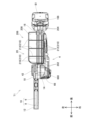
(実施例1)
図1に示すように、本実施例の作業機は、チェーンソーT1である。チェーンソーT1は、主に木材や木の枝等の切断作業に用いられる、いわゆるプルーニングチェーンソーである。チェーンソーT1全体の重量は、大きくとも約2000gと比較的軽量である。これにより、チェーンソーT1は、片手で持ち運び可能となっている。
(Example 1)
As shown in FIG. 1, the work machine of this embodiment is a chainsaw T1. The chainsaw T1 is a so-called pruning chainsaw that is mainly used for cutting wood, tree branches, and the like. The entire weight of the chainsaw T1 is approximately 2000 g at most, which is relatively light. This allows the chainsaw T1 to be carried with one hand.
チェーンソーT1は、ハウジング4と、ガイドバー6と、ソーチェーン8と、ハンドガード20と、電池パックB1を備えている。ガイドバー6は、ハウジング4から前方に向けて突出するようにハウジング4に取り付けられた、細長い板状の部材である。ガイドバー6は、例えば鉄等の金属材料からなる。ソーチェーン8は、相互に連結された複数のカッタ(図示せず)を備えており、ガイドバー6の周縁に沿って取り付けられている。ハウジング4には、略直方体形状の電池パックB1が取り付けられている。チェーンソーT1は、電池パックB1から供給される電力によって、ソーチェーン8をガイドバー6の周縁に沿って走行させる。
The chainsaw T1 includes a
ガイドバー6としては、切断作業の内容に応じて、種々のものを取付可能である。ガイドバー6の先端の曲率半径は、例えば15mmである。本実施例のチェーンソーT1は、ソーチェーン8を、例えば8m/sの速度で、ガイドバー6の周縁に沿って走行する。本明細書では、ガイドバー6とソーチェーン8を総称して「作業部10」と呼ぶことがある。本実施例では、作業部10の重量は、例えば約180gである。また、ハウジング4には、作業部10の一部を覆う作業カバー12が設けられている。このため、ユーザは、作業部10のうち作業カバー12により覆われていない部分を被切断物(例えば、木の枝)に押し当てることで、切断作業を実行する。この際、ユーザがチェーンソーT1に与える荷重は大きくとも20N程度であると想定される。
Various types of
以下の説明では、ガイドバー6の長手方向において、ハウジング4からガイドバー6に向かう方向を前方向とし、ガイドバー6からハウジング4に向かう方向を後方向とする。そして、前後方向に直交する方向であって、作業部10から作業カバー12に向かう方向を上方向とし、作業カバー12から作業部10に向かう方向を下方向とする。そして、前後方向および上下方向に直交する方向を左右方向とする。なお、図1から図15では、図示の簡略化のため、ソーチェーン8をガイドバー6と面一な輪状の部材として図示している。
In the following description, in the longitudinal direction of the
ハウジング4は、ハウジング本体14と、グリップ16と、第1取付部22と、第2取付部24を備えている。ハウジング本体14は、前後方向に対して、前方から後方に向かうにつれて下方から上方に向かうように傾斜した、略直方体形状を有している。ハウジング本体14は、前方において、スプロケットカバー18とともに作業部10を保持している。グリップ16は、ハウジング本体14の前方下部に接続している。グリップ16は、前後方向に対して、前方から後方に向かうにつれて上方から下方に傾斜した、略円筒形状を有している。第1取付部22は、ハウジング4の下方に突出して設けられるとともに、グリップ16の基端近傍に配置されている。第2取付部24は、ハウジング4の下方に突出して設けられるとともに、グリップ16の先端近傍に配置されている。第1取付部22および第2取付部24には、ハンドガード20が取り付けられる。ハウジング4(ハウジング本体14と、グリップ16と、第1取付部22と、第2取付部24)には、ヤング率が100MPaよりも大きい材料が用いられる。本実施例のハウジング4には、例えばポリアミド等のプラスチック材料が用いられている。ポリアミドのヤング率は、周囲の環境により変化することがあるが、少なくとも5000MPaよりは大きいといえる。なお、ユーザの手指が置かれる部分(ハウジング本体14の頭部14aと、グリップ16の周囲)には、例えばニトリルブタジエンゴム等のゴム材料によるコーティングが施されている。
The
電池パックB1は、例えばリチウムイオン電池等の、再充電可能な二次電池を収容している。電池パックB1の出力電圧は、例えば10Vである。電池パックB1の電池容量は、例えば1.5Ahである。電池パックB1の重量は、例えば約215gである。図3に示すように、電池パックB1の下面には、表示部166が設けられている。表示部166は、電池パックB1の電池残量に応じて表示を変化させることで、電池パックB1の電池残量をユーザに報知する。
The battery pack B1 contains a rechargeable secondary battery, such as a lithium ion battery. The output voltage of battery pack B1 is, for example, 10V. The battery capacity of the battery pack B1 is, for example, 1.5 Ah. The weight of the battery pack B1 is, for example, about 215 g. As shown in FIG. 3, a
図2に示すように、グリップ16の先端には、電池パックB1を着脱可能に受け入れるための電池インタフェース160が設けられている。電池パックB1は、電池インタフェース160に対して後方上方から前方下方にスライドさせることで取り付けられる。また、電池インタフェース160は、電池パックB1が備える端子(図示せず)と接続するための接続端子162を備えている。接続端子162は、後述する制御ユニット62(図6参照)およびトリガスイッチ52(図6参照)に電気的に接続されている。電池パックB1が電池インタフェース160に取り付けられると、電池パックB1が備える端子と接続端子162が電気的に接続される。これにより、電池パックB1から制御ユニット62およびトリガスイッチ52への電力供給が許容される。
As shown in FIG. 2, a
図1に示すように、電池パックB1が電池インタフェース160に取り付けられた状態では、電池パックB1とグリップ16の外表面は滑らかに接続している。また、電池パックB1は、電池パックB1に設けられたフック164を押し込んだ状態で、電池インタフェース160に対して前方下方から後方上方にスライドさせることで取り外される。
As shown in FIG. 1, when the battery pack B1 is attached to the
図4に示すように、スプロケットカバー18は、スプロケットカバー本体36と係止部材42を備えている。スプロケットカバー本体36は、スリーブ38を備えている。係止部材42は、係止部材本体44と、ナット46と、爪部48を備えている。スプロケットカバー18の内側では、スプロケット26がハウジング本体14の外側に露出している。スプロケット26には、ガイドバー6からソーチェーン8が架け渡される。また、ガイドバー6には、前後方向に沿って延びる切り欠き6aが形成されている。切り欠き6aには、ハウジング本体14の左側面から突出して固定されたピン28、30およびボルト32が右方から嵌入されている。
As shown in FIG. 4, the
図4に示す状態から、スプロケットカバー本体36のスリーブ38にボルト32を挿入し、スリーブ38を貫通するボルト32に対して係止部材42のナット46を締結することで、ハウジング本体14に対してスプロケットカバー18を取り付けることができる。ボルト32にナット46が締結された状態では、ガイドバー6は、ハウジング本体14とスプロケットカバー18の間に挟み込まれて固定される。ユーザは、ボルト32とナット46を緩めた状態で、ハウジング本体14に対してガイドバー6を前後方向にスライドさせることで、ガイドバー6とスプロケット26の距離を変化させて、ソーチェーン8の張り具合を調整することができる。
From the state shown in FIG. 4, the
ユーザは、係止部材本体44に対して左方に起立させた爪部48をボルト32の軸線周りに回転させることで、ボルト32とナット46を締めたり、緩めたりすることができる。これにより、ユーザは、特段の工具を用いることなく、十分な締め付けトルクでナット46をボルト32に締結することができる。なお図1に示すように、通常時の爪部48は、捩りばね(図示せず)によって、係止部材本体44に沿って寝かせた状態となるように保持されている。
The user can tighten or loosen the
図2に示すように、グリップ16の基端近傍の下面には、ユーザが作業部10を駆動操作するためのトリガレバー50が配置されている。図5に示すように、トリガレバー50は、左右方向に延びる回動軸50a周りに回動可能に、ハウジング4に支持されている。ユーザは、トリガレバー50をグリップ16側に向けて引き上げ操作することができる。また、本明細書では、トリガレバー50のうち、グリップ16の外側に露出している部分の前端を、単に「前端50f」と呼ぶ。トリガレバー50のうち、グリップ16の外側に露出している部分の後端を、単に「後端50r」と呼ぶ。
As shown in FIG. 2, a
ハウジング4の内部には、ユーザによるトリガレバー50の引き上げ操作を検出するトリガスイッチ52が設けられている。トリガスイッチ52は、トリガレバー50の直上に配置されており、グリップ16とハウジング本体14の間に跨っている。トリガスイッチ52は、後述する制御ユニット62(図6参照)に電気的に接続されている。トリガスイッチ52は、トリガレバー50が引き上げ操作されている間、制御ユニット62に対してトリガオン信号を出力する。また、ハウジング4の内部には、ユーザによるトリガレバー50の操作を許可する状態と禁止する状態の間で切り換えるロック部材54がさらに設けられている。ロック部材54は、トリガレバー50の直上であって、トリガスイッチ52の前方に配置されている。ロック部材54は、左右方向に延びる回動軸54a周りに回動可能に、ハウジング4に支持されている。
A
ロック部材54が上方に回動した状態では、ロック部材54がトリガレバー50と機械的に干渉することで、トリガレバー50の上方への回動が禁止される。ロック部材54が下方に回動した状態では、ロック部材54がトリガレバー50と干渉しなくなり、トリガレバー50の上方への回動が許容される。
When the
図1に示すように、ロック部材54は、ハウジング4の左側面に設けられた貫通孔56aを介してハウジング4の外側に突出した左側ロックレバー58aを備えている。図2に示すように、ロック部材54は、ハウジング4の右側面に設けられた貫通孔56bを介してハウジング4の外側に突出した右側ロックレバー58bを備えている。以下では、左側ロックレバー58aと右側ロックレバー58bを総称して「ロックレバー58」と呼ぶ。ユーザは、ロックレバー58を介して、ロック部材54を回動操作することができる。
As shown in FIG. 1, the
トリガレバー50とロック部材54は、捩りバネ60(図5参照)によって互いに連結されている。捩りバネ60は、トリガレバー50を下方に回動する方向に付勢するとともに、ロック部材54を上方に回動する方向に付勢する。このため、ユーザがトリガレバー50から手を離している場合には、捩りバネ60の付勢力によってトリガレバー50は下方に回動した状態となる。また、ユーザがロックレバー58から手を離している場合には、捩りバネ60の付勢力によってロック部材54は上方に回動した状態となる。
The
例えば、ユーザは、チェーンソーT1を使用する際、右手でグリップ16を把持し、左手を頭部14aに添えて、チェーンソーT1を保持する。この状態から、ユーザがロックレバー58を右手の親指で押し下げると、ユーザによるトリガレバー50の操作が許可された状態となり、この状態でユーザがトリガレバー50を右手の人差し指で引き上げ操作することで、作業部10が駆動される。
For example, when using the chainsaw T1, the user holds the chainsaw T1 by gripping the
(ハンドガード20の構成)
図1に示すハンドガード20は、グリップ16を把持するユーザの手を保護するための保護具である。ユーザによる切断作業の実行中(作業部10の駆動中)にソーチェーン8が破断すると、破断したソーチェーン8が、走行時の勢いを保ったままガイドバー6から飛び出すことがある。このような場合に、ハンドガード20は、ガイドバー6から飛び出したソーチェーン8が、グリップ16(図1参照)を把持するユーザの手に接触することを抑制することができる。ハンドガード20には、例えば、ヤング率が1MPaから100MPaまでの範囲内にある材料が用いられる。本実施例のハンドガード20には、例えばニトリルブタジエンゴム等のゴム材料が用いられている。ニトリルブタジエンゴムのヤング率は、周囲の環境により変化することがあるが、1MPaから10MPaまでの範囲内にはあるといえる。
(Configuration of hand guard 20)
The
ハンドガード20は、第1端部202と、第2端部204と、第1端部202と第2端部204の間で連続的に延びるガード本体206を備えている。第1端部202は、左右方向に延びる回動軸22a周りに回動可能に、第1取付部22に取り付けられている。第1端部202は、第1取付部22に取り付けられることで、グリップ16の基端近傍に配置される。また、第2端部204は、左右方向に延びる回動軸24a(図2参照)周りに回動可能に、第2取付部24に取り付けられている。第2端部204は、第2取付部24に取り付けられることで、グリップ16の先端近傍に配置される。
The
ガード本体206は、板状に形成されたプレート部208と、プレート部208の下面から下方に突出した複数のリブ部210(図3参照)を備えている。プレート部208は、上面がグリップ16に対向するように配置されている。本実施例では、プレート部208の厚さ(プレート部208の上面および下面に直交する方向における厚さ)は、例えば約5mmである。
The guard
図3に示すように、チェーンソーT1を下方から見た時、プレート部208は略矩形形状を有している。プレート部208は、ガイドバー6の左面よりも左方において、例えば約29mmの幅を有している。プレート部208は、ガイドバー6の右面よりも右方において、例えば約30mmの幅を有している。また、プレート部208は、グリップ16(図1参照)の左面よりも左方において、例えば約30mmの幅を有している。プレート部208は、グリップ16の右面よりも右方において、例えば約0.5mmの幅を有している。
As shown in FIG. 3, when the chainsaw T1 is viewed from below, the
複数のリブ部210は、プレート部208の下面に沿って前後方向に延びる第1リブ部212と、プレート部208の下面に沿って左右方向に延びる第2リブ部214と、プレート部208の下面の周縁部に沿って延びる第3リブ部216を備えている。第1リブ部212は、左右方向に4つ並べられている。チェーンソーT1を下方から見た時、第1リブ部212のそれぞれは、第1端部202と第2端部204の間を略直線状に延びている。また、第2リブ部214は、前後方向に3つ並べられている。第1リブ部212と、第2リブ部214は、互いに直交する部分において接続している。第2リブ部214は、左端および右端において、第3リブ部216と接続している。
The plurality of
図6に示すように、プレート部208は、基端側から先端側に向かうにつれてグリップ16から離れるように延びる第1延伸部220と、先端側から基端側に向かうにつれてグリップ16から離れるように延びる第2延伸部222と、第1延伸部220と第2延伸部222を接続する屈曲部224から構成されている。第1延伸部220の延伸方向における長さは、第2延伸部222の延伸方向における長さよりも短くなっている。屈曲部224の屈曲角度は、例えば100°である。屈曲部224の曲率半径は、例えば18mmである。これにより、自然状態(ハンドガード20に外力が加わっていない状態)では、ハンドガード20は、グリップ16から見て外側に突き出したような形状となっている。
As shown in FIG. 6, the
上記の説明の通りに構成されたハンドガード20では、ハンドガード20は、ハウジング4よりも弾性変形しやすくなっている。ハンドガード20は、例えば、プレート部208の下面に対向する方向から、5N以下の所定の荷重がかかることで、変形し始めるように構成されている。なお、ここでいう「変形し始める」とは、ハンドガード20の弾性ひずみが1%を上回ることを意味している。このため、ユーザは、比較的小さな荷重をもって、ハンドガード20を変形させることができる。
In the
(チェーンソーT1の内部構造)
図6に示すように、ハウジング本体14の内部には、制御ユニット62と、電動モータ64と、オイルタンク66と、オイルポンプ68と、減速機72と、冷却ファン82が収容されている。
(Internal structure of chainsaw T1)
As shown in FIG. 6, a
図7に示すように、電動モータ64は、インナロータ型のDCブラシレスモータである。電動モータ64は、コイル74が巻回されたステータ76と、ステータ76の内側に配置されており、永久磁石(図示せず)を備えるロータ78と、を備えている。本実施例では、電動モータ64(コイル74と、ステータ76と、ロータ78)の重量は、例えば約180gである。なお、ロータ78には、ステータ76およびロータ78の中央を貫通するように配置されたモータシャフト80が固定されている。このため、電動モータ64は、モータシャフト80を回転駆動するように構成されている。
As shown in FIG. 7, the
冷却ファン82は、ロータ78よりも下方において、モータシャフト80に固定されている。冷却ファン82は、モータシャフト80の回転に伴って回転する。冷却ファン82が回転すると、モータシャフト80の軸線A1(図6参照)に沿って下方から上方に向かう空気の流れが形成される。この時、左側吸気口140(図1参照)および右側吸気口142(図2参照)を通じて、ハウジング4の外部から内部に空気が吸入される。また、左側排気口144(図1参照)および右側排気口146(図2参照)を通じて、ハウジング4の内部から外部に空気が排出される。これにより、冷却ファン82は、電動モータ64の駆動に伴って電動モータ64を冷却することができる。
The cooling
減速機72は、冷却ファン82よりも下方においてモータシャフト80に固定された第1ベベルギヤ72aと、第1ベベルギヤ72aに噛み合う第2ベベルギヤ72bを備えている。第2ベベルギヤ72bは、駆動シャフト84に固定されている。駆動シャフト84は、左右方向に延びる回転軸周りに回転可能に、ハウジング4(図1参照)に支持されている。駆動シャフト84には、第2ベベルギヤ72bの左方において、スプロケット26が固定されている。このため、電動モータ64が駆動すると、モータシャフト80の回転運動が、減速機72、駆動シャフト84、およびスプロケット26を介してソーチェーン8に伝達される。これによってソーチェーン8がスプロケット26とガイドバー6の周りを回転する。
The
図6に示すオイルタンク66は、ソーチェーン8を潤滑するための潤滑油を貯留するためのタンクである。オイルタンク66は、最大約50ccの潤滑油を貯留することができる。オイルタンク66には、オイルタンク66に潤滑油を補充するための給油口(図示せず)が設けられている。給油口には、キャップ660が着脱可能に取り付けられている。オイルタンク66は、ハウジング本体14の前端近傍に配置されている。図2に示すように、オイルタンク66のキャップ660および給油口は、ハウジング本体14の外部に露出している。このため、ユーザは、ハウジング本体14を分解することなく、給油口からキャップ660を取り外して、オイルタンク66への給油を行うことができる。
The
図7に示すように、駆動シャフト84には、第2ベベルギヤ72bの右方において、ウォームギヤ84aが固定されている。ウォームギヤ84aは、オイルポンプ68のウォームホイール68aに噛み合っている。このため、電動モータ64が駆動すると、モータシャフト80の回転運動が、減速機72、駆動シャフト84、ウォームギヤ84a、およびウォームホイール68aを介してオイルポンプ68に伝達される。これによってオイルポンプ68が駆動される。オイルポンプ68が駆動されると、オイルタンク66(図6参照)の内部に配置された吸込部680を介して、潤滑油がオイル供給路682へと吸引される。そして、吐出部684を介して、オイル供給路682からガイドバー6およびソーチェーン8に潤滑油が供給される。
As shown in FIG. 7, a
本明細書では、減速機72と、駆動シャフト84と、ウォームギヤ84aから構成される機構を「動力伝達機構70」と呼ぶことがある。図6に示すように、動力伝達機構70は、ハウジング本体14の中央部分に配置されている。動力伝達機構70は、電動モータ64の前方かつ下方に配置されている。動力伝達機構70は、オイルタンク66よりも後方に配置されている。本実施例では、動力伝達機構70の重量は、例えば約110gである。
In this specification, a mechanism including the
制御ユニット62は、ハウジング本体14の頭部14aの直下に配置されている。制御ユニット62は、電動モータ64の上方かつ後方に配置されている。制御ユニット62の下方であって、電動モータ64の後方には、配線空間Sが形成されている。図示しないが、制御ユニット62や電動モータ64等の各構成部品間を電気的に接続する導線の大部分は、配線空間Sを通じて配線される。
The
制御ユニット62は、複数のスイッチング素子を備えるインバータ回路およびそれぞれのスイッチング素子の動作を制御する制御回路が搭載された制御基板(図示せず)と、制御基板を収容する略直方体形状のコントローラケース620を備えている。コントローラケース620には、例えばアルミニウム等の金属材料が用いられている。本実施例では、制御ユニット62の重量は、例えば約60gである。
The
制御ユニット62は、トリガスイッチ52からトリガオン信号が出力されている間、電池パックB1から供給される直流電力を三相交流電力に変換して、電動モータ64へ供給する。制御ユニット62は、トリガスイッチ52からトリガオン信号が出力されなくなると、電池パックB1から電動モータ64への電力供給を遮断する。また、制御ユニット62は、ソーチェーン8を所定の走行方向に走行させるように、電動モータ64の駆動を制御する。ここでいう所定の走行方向とは、ソーチェーン8が、ガイドバー6の上方では前方に走行し、ガイドバー6の下方では後方に走行するような方向である。
The
(主な構成部品の軸線A1に対する位置関係)
モータシャフト80(図7参照)の軸線A1は、前後上下方向に広がる平面上に配置されている。軸線A1は、上下方向に対して、上方から下方に向かうにつれて後方から前方に向かうように傾斜している。軸線A1の上下方向に対する傾斜角度は、本実施例では41°である。制御ユニット62は、軸線A1上に配置されている。制御ユニット62(コントローラケース620)は、軸線A1に略直交する平面に沿って配置されている。軸線A1から制御ユニット62の前端62f(コントローラケース620の前端に一致)までの距離は、軸線A1から制御ユニット62の後端62r(コントローラケース620の後端に一致)までの距離よりも小さい。また、動力伝達機構70の駆動シャフト84は、軸線A1に略直交するように配置されている。
(Positional relationship of main components with respect to axis A1)
The axis A1 of the motor shaft 80 (see FIG. 7) is arranged on a plane that extends in the front-back and up-down directions. The axis A1 is inclined with respect to the vertical direction from the top to the bottom and from the rear to the front. The angle of inclination of the axis A1 with respect to the vertical direction is 41° in this embodiment. The
図8に示すように、軸線A1に直交する方向に沿って前方からハウジング本体14(図1参照)の内部を見た時、上方から順に、制御ユニット62と、電動モータ64と、冷却ファン82と、動力伝達機構70およびスプロケット26と、オイルタンク66が、略一列に並んで配置されている。軸線A1に直交する方向に沿って前方から見た時、制御ユニット62の重心位置62Gと、電動モータ64の重心位置64Gと、冷却ファン82の重心位置82Gは、それぞれ軸線A1上に配置されている。
As shown in FIG. 8, when the inside of the housing body 14 (see FIG. 1) is viewed from the front along the direction perpendicular to the axis A1, the
軸線A1に直交する方向に沿って前方から見た時、制御ユニット62と、電動モータ64と、冷却ファン82のそれぞれは、略左右対称(軸線A1に関して略線対称)の形状を有している。図示しないが、グリップ16(図1参照)および電池パックB1(図1参照)も同様に、略左右対称(軸線A1に関して略線対称)の形状を有している。また、スプロケット26は、軸線A1よりも左方に配置されている。オイルタンク66と、オイルポンプ68と、第2ベベルギヤ72bと、ウォームギヤ84aは、軸線A1よりも右方に配置されている。
When viewed from the front along the direction perpendicular to the axis A1, the
(主な構成部品のトリガレバー50に対する位置関係)
図6では、トリガレバー50の前端50fを通り、上下方向に延びる直線A2と、トリガレバー50の後端50rを通り、上下方向に延びる直線A3を図示している。
(Positional relationship of main components with respect to trigger lever 50)
FIG. 6 shows a straight line A2 passing through the
制御ユニット62の前端62fは、トリガレバー50の後端50rよりも後方に配置されている。電動モータ64の前端64fは、トリガレバー50の前端50fよりも後方であって、トリガレバー50の後端50rよりも前方に配置されている。動力伝達機構70の後端70r(第1ベベルギヤ72aの後端に一致)は、トリガレバー50の前端50fよりも後方であって、トリガレバー50の後端50rよりも前方に配置されている。電池パックB1の前端B1fは、トリガレバー50の後端50rよりも後方に配置されている。また、制御ユニット62の重心位置62Gは、トリガレバー50の後端50rよりも後方に配置されている。電動モータ64の重心位置64Gは、トリガレバー50の後端50rよりも後方に配置されている。冷却ファン82の重心位置82Gは、トリガレバー50の前端50fよりも後方であって、トリガレバー50の後端50rよりも前方に配置されている。電池パックB1の重心位置BG1は、トリガレバー50の後端50rよりも後方に配置されている。
The
上記の説明の通りに構成されたチェーンソーT1では、チェーンソーT1の重心位置TG1は、ハウジング4の内部であって、直線A2と直線A3の間に配置されている。重心位置TG1は、ロック部材54と重なる位置にあるともいえる。また、直線A2から重心位置TG1までの距離と、直線A3から重心位置TG1までの距離は、略同一となっている。なお、本実施例では、オイルタンク66に満量の潤滑油が貯留された状態、電池パックB1が電池インタフェース160に取り付けられた状態、かつ、その他の構成部品がすべて取り付けられた状態で、重心位置TG1を定めている。
In the chainsaw T1 configured as described above, the center of gravity TG1 of the chainsaw T1 is located inside the
(実施例2)
図9に示すように、本実施例の作業機は、チェーンソーT2である。チェーンソーT2は、電池パックB1の代わりに電池パックB2を備える点を除いて、実施例1のチェーンソーT1と略同様の構成を備えている。以下では、チェーンソーT2とチェーンソーT1の相違点についてのみ説明を行う。
(Example 2)
As shown in FIG. 9, the working machine of this embodiment is a chainsaw T2. The chainsaw T2 has substantially the same configuration as the chainsaw T1 of the first embodiment, except that it includes a battery pack B2 instead of the battery pack B1. Below, only the differences between the chainsaw T2 and the chainsaw T1 will be explained.
電池パックB2は、例えばリチウムイオン電池等の、再充電可能な二次電池を収容している。電池パックB2の出力電圧は、例えば10Vである。電池パックB2の電池容量は、例えば4.0Ahである。電池パックB2の重量は、例えば約375gである。電池パックB2は、電池パックB1と同様に、電池インタフェース160に対して着脱可能に取り付けられる。
Battery pack B2 houses a rechargeable secondary battery, such as a lithium ion battery. The output voltage of battery pack B2 is, for example, 10V. The battery capacity of battery pack B2 is, for example, 4.0 Ah. The weight of the battery pack B2 is, for example, about 375 g. Battery pack B2, like battery pack B1, is detachably attached to
電池パックB2は、電池パックB1(図2参照)と比較して、グリップ16の延在方向における幅が大きくなっている。電池パックB2の左右方向における幅は、電池パックB1と同程度である。電池パックB2の、グリップ16の延在方向および左右方向に直交する方向における幅は、電池パックB1と同程度である。これにより、電池パックB2の体積は、電池パックB1の体積よりも大きくなっている。
The battery pack B2 has a larger width in the extending direction of the
図10に示すように、電池パックB2の前端B2fおよび重心位置BG2は、トリガレバー50の後端50rよりも後方に配置されている。また、チェーンソーT2の重心位置TG2は、ハウジング4の内部であって、直線A2と直線A3の間に配置されている。重心位置TG2は、トリガスイッチ52の前端近傍に位置しているともいえる。また、直線A2から重心位置TG2までの距離は、直線A3から重心位置TG2までの距離よりも、大きくなっている。
As shown in FIG. 10, the front end B2f and center of gravity position BG2 of the battery pack B2 are arranged rearward than the
(実施例3)
図11に示すように、本実施例の作業機は、チェーンソーT3である。チェーンソーT3は、電池パックB1の代わりに電池パックB3を備え、電池インタフェース160の代わりに電池インタフェース360を備える点を除いて、実施例1のチェーンソーT1と略同様の構成を備えている。以下では、チェーンソーT3とチェーンソーT1の相違点についてのみ説明を行う。
(Example 3)
As shown in FIG. 11, the work machine of this embodiment is a chainsaw T3. The chainsaw T3 has substantially the same configuration as the chainsaw T1 of the first embodiment, except that it includes a battery pack B3 instead of the battery pack B1 and a
電池パックB3は、例えばリチウムイオン電池等の、再充電可能な二次電池を収容している。電池パックB3の出力電圧は、例えば18Vである。電池パックB3の電池容量は、例えば2.0Ahである。電池パックB3の重量は、例えば約375gである。電池パックB3のグリップ16の延在方向における幅は、電池パックB1(図2参照)と同程度である。電池パックB3は、電池パックB1と比較して、左右方向における幅が大きくなっている。電池パックB3は、電池パックB1と比較して、グリップ16の延在方向および左右方向に直交する方向における幅が大きくなっている。これにより、電池パックB3の体積は、電池パックB1の体積よりも大きくなっている。
Battery pack B3 contains a rechargeable secondary battery, such as a lithium ion battery. The output voltage of battery pack B3 is, for example, 18V. The battery capacity of the battery pack B3 is, for example, 2.0 Ah. The weight of the battery pack B3 is, for example, about 375 g. The width of the battery pack B3 in the extending direction of the
電池パックB3は、電池インタフェース360に対して後方上方から前方下方にスライドさせることで取り付けられる。また、電池インタフェース360は、電池パックB3が備える端子(図示せず)と接続するための接続端子362を備えている。接続端子362は、制御ユニット62(図12参照)およびトリガスイッチ52(図12参照)に電気的に接続されている。電池パックB3が電池インタフェース360に取り付けられると、電池パックB3が備える端子と接続端子362が電気的に接続される。これにより、電池パックB3から制御ユニット62およびトリガスイッチ52への電力供給が許容される。
The battery pack B3 is attached to the
図12に示すように、電池パックB3が電池インタフェース360に取り付けられた状態では、電池パックB3とグリップ16の外表面は滑らかに接続している。また、電池パックB3は、電池パックB3に設けられたフック364(図11参照)を押し込んだ状態で、電池インタフェース360に対して前方下方から後方上方にスライドさせることで取り外される。
As shown in FIG. 12, when the battery pack B3 is attached to the
電池パックB3の前端B3fおよび重心位置BG3は、トリガレバー50の後端50rよりも後方に配置されている。また、チェーンソーT3の重心位置TG3は、ハウジング4の内部であって、直線A2と直線A3の間に配置されている。重心位置TG3は、トリガスイッチ52の前端近傍に位置しているともいえる。また、直線A2から重心位置TG3までの距離は、直線A3から重心位置TG3までの距離よりも、大きくなっている。なお、チェーンソーT3の重心位置TG3は、実施例2のチェーンソーT2の重心位置TG2と略同一の位置にある。
The front end B3f and the center of gravity position BG3 of the battery pack B3 are arranged rearward than the
(実施例4)
図13に示すように、本実施例の作業機は、チェーンソーT4である。チェーンソーT4は、電池パックB3の代わりに電池パックB4を備える点を除いて、実施例3のチェーンソーT3と略同様の構成を備えている。以下では、チェーンソーT4とチェーンソーT3の相違点についてのみ説明を行う。
(Example 4)
As shown in FIG. 13, the work machine of this embodiment is a chainsaw T4. The chainsaw T4 has substantially the same configuration as the chainsaw T3 of the third embodiment, except that it includes a battery pack B4 instead of the battery pack B3. Below, only the differences between the chainsaw T4 and the chainsaw T3 will be explained.
電池パックB4は、例えばリチウムイオン電池等の、再充電可能な二次電池を収容している。電池パックB4の電圧は、例えば18Vである。電池パックB4の電池容量は、例えば6.0Ahである。電池パックB4の重量は、例えば約670gである。電池パックB4は、電池パックB3と同様に、電池インタフェース360に対して着脱可能に取り付けられる。
Battery pack B4 contains a rechargeable secondary battery, such as a lithium ion battery. The voltage of battery pack B4 is, for example, 18V. The battery capacity of battery pack B4 is, for example, 6.0 Ah. The weight of the battery pack B4 is, for example, about 670 g. Battery pack B4, like battery pack B3, is detachably attached to
電池パックB4は、電池パックB3(図11参照)と比較して、グリップ16の延在方向における幅が大きくなっている。電池パックB4の左右方向における幅は、電池パックB3と同程度である。電池パックB4の、グリップ16の延在方向および左右方向に直交する方向における幅は、電池パックB3と同程度である。これにより、電池パックB4の体積は、電池パックB3の体積よりも大きくなっている。
The battery pack B4 has a larger width in the extending direction of the
図14に示すように、電池パックB4の前端B4fおよび重心位置BG4は、トリガレバー50の後端50rよりも後方に配置されている。また、チェーンソーT4の重心位置TG4は、ハウジング4の内部であって、ハウジング4の内部であって、直線A3よりも後方に配置されている。重心位置TG3は、トリガスイッチ52の後端近傍に位置しているともいえる。
As shown in FIG. 14, the front end B4f and center of gravity position BG4 of the battery pack B4 are arranged rearward than the
以下では、チェーンソーT1と、チェーンソーT2と、チェーンソーT3と、チェーンソーT4を総称して「チェーンソーT」と呼ぶことがある。 Hereinafter, chainsaw T1, chainsaw T2, chainsaw T3, and chainsaw T4 may be collectively referred to as "chainsaw T."
(変形例)
上記の実施例では、作業機が、作業部10としてガイドバー6およびソーチェーン8を備えるチェーンソーTである構成について説明した。別の実施例では、作業機は、作業部10として鋸刃を備えるレシプロソーであってもよい。なお、作業機がレシプロソーである場合には、作業機はオイルタンク66およびオイルポンプ68を備えていなくてもよい。
(Modified example)
In the above embodiment, the working machine is a chainsaw T including a
上記の実施例では、電動モータ64がインナロータ型のDCブラシレスモータである構成について説明した。別の実施例では、電動モータ64は、アウタロータ型のDCブラシレスモータであってもよい。あるいは、電動モータ64は、ブラシ付きモータであってもよいし、他の種類の電動モータであってもよい。
In the above embodiment, the
上記の実施例では、ハウジング4には、ポリアミド等のプラスチック材料が用いられている構成について説明した。別の実施例では、ハウジング4には、ヤング率が100MPaよりも大きい材料であれば、ポリアミド以外のプラスチック材料(例えば、ポリカーボネート)が用いられてもよい。さらに別の実施例では、ハウジング4には、ヤング率が100MPaよりも大きい材料であれば、プラスチック材料以外の材料(例えば、アルミニウム等の金属材料)が用いられてもよい。
In the above embodiment, the
上記の実施例では、ハンドガード20には、ニトリルブタジエンゴム等のゴム材料が用いられている構成について説明した。別の実施例では、ハンドガード20には、ヤング率が1MPaから100MPaまでの範囲内にある材料であれば、ニトリルブタジエンゴム以外のゴム材料(例えば、エチレンプロピレンゴム)が用いられてもよい。
In the above embodiment, the
上記の実施例において、ハンドガード20の第1端部202および第2端部204の少なくとも一方は、対応する第1取付部22および第2取付部24の少なくとも一方に対して、回転不能に取り付けられていてもよい。
In the above embodiment, at least one of the
上記の実施例において、ハンドガード20の複数のリブ部210は、第1リブ部212、第2リブ部214、および第3リブ部216のうち、少なくとも1つを備えていなくてもよい。
In the above embodiment, the plurality of
上記の実施例では、ハンドガード20が、比較的ヤング率の低い材料(ゴム材料)によって形成されることで、ハウジング4よりも弾性変形しやすくなっている構成について説明した。別の実施例では、ハンドガード20は、ハウジング4に対して揺動可能に設けられた、いわゆるスイングドアのような構成としてもよい。この場合、ハンドガード20が障害物に当接した状態で、ハンドガード20に荷重がかかると、ハンドガード20は閉状態から開状態に変形する。さらに別の実施例では、ハンドガード20は、ハウジング4に対して第1位置と第2位置の間で並進可能に設けられる構成としてもよい。この場合、ハンドガード20が障害物に当接した状態で、ハンドガード20に荷重がかかると、ハンドガード20が第1位置と第2位置の間で並進することにより、ハウジング4に対するハンドガード20の位置が変化する。なお、ハンドガード20を弾性変形以外の方法で変形させる場合には、ハンドガード20には、ゴム材料以外の材料(例えば、ポリアミド等のプラスチック材料)が用いられてもよいし、ヤング率が100MPaよりも大きい材料が用いられてもよい。
In the above embodiment, the
上記の実施例において、チェーンソーT(作業機の例)は、動力伝達機構70を備えていなくてもよい。この場合、例えば、スプロケット26に複数の歯が形成されており、スプロケット26の複数の歯が、モータシャフト80に固定された第1ベベルギヤ72aと噛み合っていてもよい。また、オイルポンプ68のウォームホイール68aは、モータシャフト80に固定された第1ベベルギヤ72aと噛み合っていてもよい。
In the above embodiment, the chainsaw T (an example of a working machine) does not need to include the
上記の実施例では、コントローラケース620には、アルミニウム等の金属材料が用いられている構成について説明した。別の実施例では、コントローラケース620には、アルミニウム以外の金属材料(例えば、鉄)が用いられていてもよい。さらに別の実施例では、コントローラケース620には、金属材料以外の材料(例えば、ポリアミド等のプラスチック材料)が用いられてもよい。
In the above embodiment, the
図15に示すように、チェーンソーT1(作業機の例)は、上記の実施例における排気口144、146の代わりに、排気口544を備えていてもよい。排気口544は、ハウジング本体14の頭部14aに設けられている。この場合、冷却ファン82が回転すると、排気口144、146の代わりに、排気口544を通じて、ハウジング4の内部から外部に空気が排出される。この場合も、冷却ファン82は、電動モータ64の駆動に伴って電動モータ64を冷却することができる。なお、上記の構成は、チェーンソーT2、T3、T4において適用されてもよい。
As shown in FIG. 15, the chainsaw T1 (an example of a working machine) may include an
(対応関係)
以上のように、1つまたはそれ以上の実施形態において、チェーンソーT(作業機の例)は、前後方向に長手方向を有する作業部10と、作業部10を駆動する電動モータ64と、電動モータ64を制御する制御ユニット62と、作業部10の後方で作業部10を保持するとともに、電動モータ64および制御ユニット62を収容するハウジング本体14と、ハウジング本体14から延びており、ユーザの一方の手によって把持されるグリップ16と、を含むハウジング4と、ハウジング4に取り付けられ、制御ユニット62を介して電動モータ64に電力を供給可能な電池パックB1(または、電池パックB2、B3、B4)と、グリップ16に設けられており、ユーザの手指でグリップ16側に引かれることによって、電動モータ64を作動するトリガレバー50と、を備えている。制御ユニット62の前端62fは、トリガレバー50の後端50rよりも後方に配置されている。
(correspondence)
As described above, in one or more embodiments, the chainsaw T (an example of a working machine) includes a working
ユーザが把持するグリップ16は、ユーザの安全性などに鑑みて、作業部10から離れた位置(例えば、チェーンソーTの後方)に設けられるのが一般的である。また、チェーンソーT全体に対する作業部10の重量が比較的大きいことも一般的である。このため、チェーンソーTでは、トリガレバー50の前端50fよりも前方に重量物(作業部10など)が偏りやすくなっており、トリガレバー50の前端50fを支点とした時のモーメントが大きくなりやすい。トリガレバー50の前端50f近傍はユーザが把持する部分であるため、トリガレバー50の前端50fを支点とした時のモーメントが大きくなると、チェーンソーTの取り回し性能は低下してしまう。これに対し、上記の構成によれば、チェーンソーTの構成部品の中でも比較的重量の大きい制御ユニット62の前端62fが、トリガレバー50の後端50rよりも後方に配置される。このため、制御ユニット62の重量により、トリガレバー50の前端50fを支点とした時のモーメントを低減できる。したがって、チェーンソーTの取り回し性能を向上することができる。
The
1つまたはそれ以上の実施形態において、電動モータ64の重心位置64Gは、トリガレバー50の後端50rよりも後方に配置されている。
In one or more embodiments, the center of
電動モータ64も、チェーンソーTの構成部品の中では比較的重量の大きい部品である。上記の構成によれば、電動モータ64の重心位置64Gが、トリガレバー50の後端50rよりも後方に配置される。このため、電動モータ64の重量により、トリガレバー50の前端50fを支点とした時のモーメントを低減できる。したがって、チェーンソーTの取り回し性能をさらに向上することができる。
The
1つまたはそれ以上の実施形態において、電動モータ64の前端64fは、トリガレバー50の前端50fよりも後方に配置されている。
In one or more embodiments, the
上記の構成によれば、電動モータ64の重量により、トリガレバー50の前端50fを支点とした時のモーメントをさらに低減できる。したがって、チェーンソーTの取り回し性能をさらに向上することができる。
According to the above configuration, the weight of the
1つまたはそれ以上の実施形態において、電池パックB1の前端B1f(または、電池パックB2の前端B2f、電池パックB3の前端B3f、電池パックB4の前端B4f)は、トリガレバー50の後端50rよりも後方に配置されている。
In one or more embodiments, the front end B1f of the battery pack B1 (or the front end B2f of the battery pack B2, the front end B3f of the battery pack B3, or the front end B4f of the battery pack B4) is closer to the
電池パックB1(または、電池パックB2、B3、B4)も、チェーンソーTの構成部品の中では比較的重量の大きい部品である。上記の構成によれば、電池パックB1の前端B1f(または、電池パックB2の前端B2f、電池パックB3の前端B3f、電池パックB4の前端B4f)が、トリガレバー50の後端50rよりも後方に配置される。このため、電池パックB1(または、電池パックB2、B3、B4)の重量により、トリガレバー50の前端50fを支点とした時のモーメントを低減できる。したがって、チェーンソーTの取り回し性能をさらに向上することができる。
The battery pack B1 (or battery packs B2, B3, B4) is also a relatively heavy component among the components of the chainsaw T. According to the above configuration, the front end B1f of the battery pack B1 (or the front end B2f of the battery pack B2, the front end B3f of the battery pack B3, or the front end B4f of the battery pack B4) is located further rearward than the
1つまたはそれ以上の実施形態において、チェーンソーTは、ハウジング本体14に収容され、電動モータ64からの動力を作業部10に伝達する動力伝達機構70をさらに備えている。動力伝達機構70の後端70rは、トリガレバー50の前端50fよりも後方に配置されている。
In one or more embodiments, the chainsaw T further includes a
チェーンソーTでは、電動モータ64と作業部10の間に動力伝達機構70(減速機72などを含む)が設けられることがある。動力伝達機構70も、チェーンソーTの構成部品の中では比較的重量の大きい部品である。上記の構成によれば、動力伝達機構70の後端70rが、トリガレバー50の前端50fよりも後方に配置される。このため、動力伝達機構70の後端70r近傍の重量により、トリガレバー50の前端50fを支点とした時のモーメントを低減できる。したがって、チェーンソーTの取り回し性能をさらに向上することができる。
In the chainsaw T, a power transmission mechanism 70 (including a
1つまたはそれ以上の実施形態において、制御ユニット62は、電動モータ64を制御する制御基板と、制御基板を収容するコントローラケース620と、を備えている。コントローラケース620には、金属材料が用いられている。
In one or more embodiments,
チェーンソーTでは、制御基板の冷却効率を向上するため、コントローラケース620に金属材料が用いられることがある。金属材料は比較的比重の大きい材料であるため、コントローラケース620に金属材料が用いられると、制御ユニット62の重量は増大する。すなわち、制御ユニット62の位置が、トリガレバー50の前端50fを支点とした時のモーメントに影響しやすくなる。上記の構成によれば、コントローラケース620に金属材料が用いられる。このため、制御基板の冷却効率を向上することができる。さらに上記の構成によれば、制御ユニット62の配置によるモーメントの低減効果がより顕著に発揮される。したがって、本願によるチェーンソーTの取り回し性能の向上効果がより顕著に発揮される。
In the chainsaw T, a metal material is sometimes used for the
1つまたはそれ以上の実施形態において、電動モータ64は、ブラシレスモータである。制御ユニット62は、電動モータ64に供給される電流を切り替えるためのスイッチング素子を備えている。
In one or more embodiments,
一般的に、電動モータ64がブラシレスモータである場合、複数のスイッチング素子における発熱によって、制御ユニット62の発熱量は比較的大きくなる。この場合、制御ユニット62を効率的に冷却するため、コントローラケース620に金属材料を用いる必要性が高い。また、コントローラケース620に金属材料が用いられると、上述の通り、本願によるチェーンソーTの取り回し性能の向上効果がより顕著に発揮される。上記の構成によれば、電動モータ64はブラシレスモータであるため、コントローラケース620に金属材料が用いられる可能性が高い。したがって、本願によるチェーンソーTの取り回し性能の向上効果がより顕著に発揮される可能性が高い。
Generally, when the
1つまたはそれ以上の実施形態において、作業部10は、前後方向に延びるガイドバー6と、ガイドバー6の周縁に設けられており、電動モータ64の駆動によりガイドバー6の周縁を走行するソーチェーン8と、を備えている。作業機は、チェーンソーTとして機能する。
In one or more embodiments, the working
上記の構成によれば、チェーンソーTの取り回し性能を向上することができる。 According to the above configuration, the handling performance of the chainsaw T can be improved.
1つまたはそれ以上の実施形態において、チェーンソーTは、ハウジング本体14に取り付けられ、ソーチェーン8を潤滑するための潤滑油を貯留するオイルタンク66をさらに備えている。オイルタンク66は、ハウジング本体14の前端近傍に配置されている。
In one or more embodiments, the chainsaw T further includes an
チェーンソーTでは、ソーチェーン8を潤滑するために、オイルタンク66に貯留された潤滑油をソーチェーン8(またはガイドバー6)に供給する必要がある。この時、オイルタンク66とソーチェーン8(またはガイドバー6)の距離が離れていると、オイル供給路682(オイルタンクからソーチェーンまたはガイドバーまでの潤滑油の供給路の例)が長くなり、チェーンソーTの大型化につながる可能性がある。これに対し、上記の構成によれば、オイルタンク66は、ハウジング本体14の前端近傍、すなわち、ソーチェーン8(またはガイドバー6)の近傍に配置される。このため、オイル供給路682を短くすることができ、チェーンソーTを小型化できる。
In the chainsaw T, in order to lubricate the
1つまたはそれ以上の実施形態において、電動モータ64は、ステータ76と、ロータ78を備えている。チェーンソーTは、ロータ78に固定されたモータシャフト80をさらに備えている。モータシャフト80の軸線A1は、前後上下方向に広がる平面上に配置されている。制御ユニット62は、モータシャフト80の軸線A1上に配置されている。
In one or more embodiments,
上記の構成によれば、制御ユニット62と電動モータ64の距離を近づけることができる。このため、制御ユニット62と電動モータ64の間を電気的に接続する導線の距離を小さくすることができる。したがって、チェーンソーTを小型化できる。
According to the above configuration, the distance between the
1つまたはそれ以上の実施形態において、軸線A1から制御ユニット62の前端62fまでの距離は、軸線A1から制御ユニット62の後端62rまでの距離よりも小さくなっている。
In one or more embodiments, the distance from axis A1 to the
一般的に、電動モータ64は、モータシャフト80の軸線A1に沿った略軸対称形状を有する。上記の構成によれば、制御ユニット62の前後方向の中心位置を、軸線A1の径方向に沿って後方にオフセットすることができる。これにより、軸線A1の径方向において、制御ユニット62の中心位置を、電動モータ64の中心位置に対して後方にオフセットすることができる。このような構成とすることで、制御ユニット62と電動モータ64の間を電気的に接続する導線を、電動モータ64の後方に配置しやすくなる。すなわち、トリガレバー50に対する導線の位置を、より後方に配置しやすくなる。電動モータ64の後方に配置される導線は、トリガレバー50の後端50rよりも後方に配置される。この場合、導線の重量により、トリガレバー50の前端50fを支点とした時のモーメントを低減できる。したがって、チェーンソーTの取り回し性能をさらに向上することができる。
Generally, the
1つまたはそれ以上の実施形態において、モータシャフト80の軸線A1に直交する方向に沿って前方からハウジング本体14の内部を見た時、制御ユニット62と、電動モータ64と、オイルタンク66と、が略一列に並んでいる。
In one or more embodiments, when looking inside the
上記の構成によれば、軸線A1の径方向に関して、ハウジング本体14を小型化できる。すなわち、軸線A1の径方向に関して、チェーンソーTを小型化できる。
According to the above configuration, the
4 :ハウジング
6 :ガイドバー
6a :切り欠き
8 :ソーチェーン
10 :作業部
12 :作業カバー
14 :ハウジング本体
14a :頭部
16 :グリップ
18 :スプロケットカバー
20 :ハンドガード
22 :第1取付部
22a :回動軸
24 :第2取付部
24a :回動軸
26 :スプロケット
28、30 :ピン
32 :ボルト
36 :スプロケットカバー本体
38 :スリーブ
42 :係止部材
44 :係止部材本体
46 :ナット
48 :爪部
50 :トリガレバー
50a :回動軸
50f :トリガレバーの前端
50r :トリガレバーの後端
52 :トリガスイッチ
54 :ロック部材
54a :回動軸
56a :貫通孔
56b :貫通孔
58a :左側ロックレバー
58b :右側ロックレバー
60 :捩りバネ
62 :制御ユニット
62G :制御ユニットの重心位置
62f :制御ユニットの前端
62r :制御ユニットの後端
64 :電動モータ
64G :電動モータの重心位置
64f :電動モータの前端
66 :オイルタンク
68 :オイルポンプ
68a :ウォームホイール
70 :動力伝達機構
70r :動力伝達機構の後端
72 :減速機
72a :第1ベベルギヤ
72b :第2ベベルギヤ
74 :コイル
76 :ステータ
78 :ロータ
80 :モータシャフト
82 :冷却ファン
82G :冷却ファンの重心位置
84 :駆動シャフト
84a :ウォームギヤ
140 :左側吸気口
142 :右側吸気口
144 :左側排気口
146 :右側排気口
160 :電池インタフェース
162 :接続端子
164 :フック
166 :表示部
202 :第1端部
204 :第2端部
206 :ガード本体
208 :プレート部
210 :リブ部
212 :第1リブ部
214 :第2リブ部
216 :第3リブ部
220 :第1延伸部
222 :第2延伸部
224 :屈曲部
360 :電池インタフェース
362 :接続端子
364 :フック
544 :排気口
620 :コントローラケース
660 :キャップ
680 :吸込部
682 :オイル供給路
684 :吐出部
B1、B2、B3、B4 :電池パック
B1f、B2f、B3f、B4f :電池パックの前端
BG1、BG2、BG3、BG4 :電池パックの重心位置
S :配線空間
T1、T2、T3、T4 :チェーンソー
TG1、TG2、TG3、TG4 :チェーンソーの重心位置
4: Housing 6: Guide bar 6a: Notch 8: Saw chain 10: Working part 12: Working cover 14: Housing body 14a: Head 16: Grip 18: Sprocket cover 20: Hand guard 22: First mounting part 22a: Rotating shaft 24: Second mounting part 24a: Rotating shaft 26: Sprockets 28, 30: Pin 32: Bolt 36: Sprocket cover body 38: Sleeve 42: Locking member 44: Locking member body 46: Nut 48: Claw Part 50: Trigger lever 50a: Rotation shaft 50f: Front end 50r of trigger lever: Rear end 52 of trigger lever: Trigger switch 54: Lock member 54a: Rotation shaft 56a: Through hole 56b: Through hole 58a: Left side lock lever 58b : Right side lock lever 60 : Torsion spring 62 : Control unit 62G : Control unit center of gravity position 62f : Control unit front end 62r : Control unit rear end 64 : Electric motor 64G : Electric motor gravity center position 64f : Electric motor front end 66 : Oil tank 68 : Oil pump 68a : Worm wheel 70 : Power transmission mechanism 70r : Rear end 72 of power transmission mechanism : Reducer 72a : First bevel gear 72b : Second bevel gear 74 : Coil 76 : Stator 78 : Rotor 80 : Motor Shaft 82: Cooling fan 82G: Cooling fan center of gravity position 84: Drive shaft 84a: Worm gear 140: Left side intake port 142: Right side intake port 144: Left side exhaust port 146: Right side exhaust port 160: Battery interface 162: Connection terminal 164: Hook 166: Display portion 202: First end portion 204: Second end portion 206: Guard body 208: Plate portion 210: Rib portion 212: First rib portion 214: Second rib portion 216: Third rib portion 220: First Extended section 222: Second extended section 224: Bent section 360: Battery interface 362: Connection terminal 364: Hook 544: Exhaust port 620: Controller case 660: Cap 680: Suction section 682: Oil supply path 684: Discharge section B1, B2 , B3, B4: Battery pack B1f, B2f, B3f, B4f: Front end of battery pack BG1, BG2, BG3, BG4: Center of gravity position of battery pack S: Wiring space T1, T2, T3, T4: Chainsaw TG1, TG2, TG3 , TG4: Chainsaw center of gravity position
Claims (9)
前記作業部を駆動する電動モータと、
前記電動モータを制御する制御ユニットと、
前記作業部の後方で前記作業部を保持するとともに、前記電動モータおよび前記制御ユニットを収容するハウジング本体と、前記ハウジング本体から延びており、ユーザの一方の手によって把持されるグリップと、を含むハウジングと、
前記ハウジングに取り付けられ、前記制御ユニットを介して前記電動モータに電力を供給可能な電池パックと、
前記グリップに設けられており、ユーザの手指で前記グリップ側に引かれることによって、前記電動モータを作動するトリガレバーと、を備えており、
前記制御ユニットの前端は、前記トリガレバーの後端よりも後方に配置されている、作業機。 a working part having a longitudinal direction in the front-rear direction;
an electric motor that drives the working part;
a control unit that controls the electric motor;
A housing body that holds the working part behind the working part and houses the electric motor and the control unit; and a grip that extends from the housing main body and is held by one hand of the user. housing and
a battery pack attached to the housing and capable of supplying power to the electric motor via the control unit;
a trigger lever provided on the grip and actuating the electric motor when pulled toward the grip by a user's finger;
In the working machine, a front end of the control unit is arranged rearward than a rear end of the trigger lever.
前記動力伝達機構の後端は、前記トリガレバーの前端よりも後方に配置されている、請求項1から4の何れか一項の作業機。 further comprising a power transmission mechanism housed in the housing body and transmitting power from the electric motor to the working part,
The working machine according to any one of claims 1 to 4, wherein a rear end of the power transmission mechanism is arranged rearward than a front end of the trigger lever.
前記コントローラケースには、金属材料が用いられている、請求項1から5の何れか一項の作業機。 The control unit includes a control board that controls the electric motor, and a controller case that houses the control board,
The working machine according to any one of claims 1 to 5, wherein a metal material is used for the controller case.
前記制御ユニットは、前記電動モータに供給される電流を切り替えるためのスイッチング素子を備えている、請求項1から6の何れか一項の作業機。 The electric motor is a brushless motor,
The working machine according to any one of claims 1 to 6, wherein the control unit includes a switching element for switching the current supplied to the electric motor.
チェーンソーとして機能する、請求項1から7の何れか一項の作業機。 The working section includes a guide bar extending in the front-rear direction, and a saw chain that is provided on the periphery of the guide bar and runs on the periphery of the guide bar by being driven by the electric motor,
The working machine according to any one of claims 1 to 7, which functions as a chainsaw.
前記オイルタンクは、前記ハウジング本体の前端近傍に配置されている、請求項8の作業機。
further comprising an oil tank attached to the housing body and storing lubricating oil for lubricating the saw chain,
The working machine according to claim 8, wherein the oil tank is located near a front end of the housing body.
Priority Applications (4)
| Application Number | Priority Date | Filing Date | Title |
|---|---|---|---|
| JP2022097397A JP2023183731A (en) | 2022-06-16 | 2022-06-16 | Work machine |
| DE102023114773.0A DE102023114773A1 (en) | 2022-06-16 | 2023-06-06 | WORKING MACHINE |
| US18/331,480 US20230405861A1 (en) | 2022-06-16 | 2023-06-08 | Working machine |
| CN202310709555.2A CN117243009A (en) | 2022-06-16 | 2023-06-15 | Work machine |
Applications Claiming Priority (1)
| Application Number | Priority Date | Filing Date | Title |
|---|---|---|---|
| JP2022097397A JP2023183731A (en) | 2022-06-16 | 2022-06-16 | Work machine |
Publications (1)
| Publication Number | Publication Date |
|---|---|
| JP2023183731A true JP2023183731A (en) | 2023-12-28 |
Family
ID=88974999
Family Applications (1)
| Application Number | Title | Priority Date | Filing Date |
|---|---|---|---|
| JP2022097397A Pending JP2023183731A (en) | 2022-06-16 | 2022-06-16 | Work machine |
Country Status (4)
| Country | Link |
|---|---|
| US (1) | US20230405861A1 (en) |
| JP (1) | JP2023183731A (en) |
| CN (1) | CN117243009A (en) |
| DE (1) | DE102023114773A1 (en) |
-
2022
- 2022-06-16 JP JP2022097397A patent/JP2023183731A/en active Pending
-
2023
- 2023-06-06 DE DE102023114773.0A patent/DE102023114773A1/en active Pending
- 2023-06-08 US US18/331,480 patent/US20230405861A1/en active Pending
- 2023-06-15 CN CN202310709555.2A patent/CN117243009A/en active Pending
Also Published As
| Publication number | Publication date |
|---|---|
| CN117243009A (en) | 2023-12-19 |
| US20230405861A1 (en) | 2023-12-21 |
| DE102023114773A1 (en) | 2023-12-21 |
Similar Documents
| Publication | Publication Date | Title |
|---|---|---|
| US20150165640A1 (en) | Battery Pack Operated Hand-Held Power Tool | |
| US10322518B2 (en) | Chainsaw | |
| JP5979364B2 (en) | Portable blower | |
| US11844317B2 (en) | Hedge trimmer | |
| EP2763816B1 (en) | Battery operated handheld power tool | |
| US10220457B2 (en) | Cutting device | |
| JP6681226B2 (en) | Chainsaw | |
| CN108064575A (en) | Hand-held with cutting accessory can carry cutter device | |
| JP2013521136A (en) | Battery powered power tools | |
| JP2019134693A (en) | Hedge trimmer | |
| US20140083729A1 (en) | Power tools | |
| US11559916B2 (en) | Electric working machine | |
| JP2023183731A (en) | Work machine | |
| US20200306847A1 (en) | Electric power work device | |
| JP2023183728A (en) | Cutting tool | |
| US20230211519A1 (en) | High power compact cordless chainsaw | |
| CN218604329U (en) | Hand-held chain saw | |
| US11141874B2 (en) | Electric-power-driven working device | |
| US11540442B2 (en) | Working machine | |
| JP2014172118A (en) | Electric power tool | |
| CN217621052U (en) | Portable chain saw | |
| JP5977386B2 (en) | Battery powered power tools | |
| US20230271345A1 (en) | Handheld battery powered chainsaw | |
| JP6990087B2 (en) | Chainsaw | |
| JP6982459B2 (en) | Chainsaw |