JP2023183205A - Rotary electric machine and vehicle driving device with the same - Google Patents
Rotary electric machine and vehicle driving device with the same Download PDFInfo
- Publication number
- JP2023183205A JP2023183205A JP2022096714A JP2022096714A JP2023183205A JP 2023183205 A JP2023183205 A JP 2023183205A JP 2022096714 A JP2022096714 A JP 2022096714A JP 2022096714 A JP2022096714 A JP 2022096714A JP 2023183205 A JP2023183205 A JP 2023183205A
- Authority
- JP
- Japan
- Prior art keywords
- flow path
- rotor
- shaft
- electric machine
- end plate
- Prior art date
- Legal status (The legal status is an assumption and is not a legal conclusion. Google has not performed a legal analysis and makes no representation as to the accuracy of the status listed.)
- Pending
Links
- 230000002093 peripheral effect Effects 0.000 claims abstract description 5
- 239000003507 refrigerant Substances 0.000 claims description 56
- 238000011144 upstream manufacturing Methods 0.000 claims description 7
- 239000007787 solid Substances 0.000 claims description 2
- 239000003921 oil Substances 0.000 description 39
- 238000003780 insertion Methods 0.000 description 17
- 230000037431 insertion Effects 0.000 description 17
- 238000001816 cooling Methods 0.000 description 12
- 239000010687 lubricating oil Substances 0.000 description 8
- 238000000034 method Methods 0.000 description 6
- 238000010586 diagram Methods 0.000 description 5
- 230000000149 penetrating effect Effects 0.000 description 4
- 230000000694 effects Effects 0.000 description 3
- 238000004891 communication Methods 0.000 description 2
- 239000007858 starting material Substances 0.000 description 2
- 229910000831 Steel Inorganic materials 0.000 description 1
- 239000002826 coolant Substances 0.000 description 1
- 230000007423 decrease Effects 0.000 description 1
- 238000005516 engineering process Methods 0.000 description 1
- 238000010030 laminating Methods 0.000 description 1
- 238000012986 modification Methods 0.000 description 1
- 230000004048 modification Effects 0.000 description 1
- 230000008929 regeneration Effects 0.000 description 1
- 238000011069 regeneration method Methods 0.000 description 1
- 239000010959 steel Substances 0.000 description 1
Images


Classifications
-
- H—ELECTRICITY
- H02—GENERATION; CONVERSION OR DISTRIBUTION OF ELECTRIC POWER
- H02K—DYNAMO-ELECTRIC MACHINES
- H02K1/00—Details of the magnetic circuit
- H02K1/06—Details of the magnetic circuit characterised by the shape, form or construction
- H02K1/22—Rotating parts of the magnetic circuit
- H02K1/32—Rotating parts of the magnetic circuit with channels or ducts for flow of cooling medium
-
- H—ELECTRICITY
- H02—GENERATION; CONVERSION OR DISTRIBUTION OF ELECTRIC POWER
- H02K—DYNAMO-ELECTRIC MACHINES
- H02K9/00—Arrangements for cooling or ventilating
- H02K9/19—Arrangements for cooling or ventilating for machines with closed casing and closed-circuit cooling using a liquid cooling medium, e.g. oil
Landscapes
- Engineering & Computer Science (AREA)
- Power Engineering (AREA)
- Motor Or Generator Cooling System (AREA)
- Iron Core Of Rotating Electric Machines (AREA)
Abstract
Description
本発明は、回転電機及びこれを備えた車両駆動装置に関する。 The present invention relates to a rotating electric machine and a vehicle drive device equipped with the same.
回転電機を冷却する技術として、例えば特許文献1乃至3に記載の技術がある。特許文献1では、シャフトの中心部に油孔を設け、シャフトの外周側に延びた供給孔を油孔に貫通させている。シャフトに組み込まれたロータには、軸方向に貫通して延びた冷却用油路と、冷却用油路の端部に冷却用油路の開口を覆うレシーバを設けている。そして、ロータが回転すると、供給孔から大気開放して吐出された潤滑油をレシーバで受け、冷却用油路に潤滑油を流してロータを冷却した後、冷却用油路から潤滑油を吐出させ、ステータのコイルエンドを冷却するようにしている。 As a technique for cooling a rotating electric machine, there are techniques described in Patent Documents 1 to 3, for example. In Patent Document 1, an oil hole is provided in the center of the shaft, and a supply hole extending toward the outer circumferential side of the shaft is passed through the oil hole. The rotor built into the shaft is provided with a cooling oil passage that extends through it in the axial direction, and a receiver that covers the opening of the cooling oil passage at the end of the cooling oil passage. When the rotor rotates, the receiver receives the lubricating oil discharged from the supply hole to the atmosphere, cools the rotor by flowing the lubricating oil into the cooling oil passage, and then discharges the lubricating oil from the cooling oil passage. , to cool the stator coil end.
特許文献2では、ロータコアに軸方向に貫通したオイル通路を形成している。ロータコアの一方の端部には、オイル通路に連通するオイル供給孔と、コイルにオイルを突出するオイル排出孔とを形成したエンドプレートを備えられている。オイル通路の断面積は、オイル流れの上流側より下流側の方が大きくなるようにしている。ロータコアの他方の端部には、断面積が拡大したオイル通路と連通するオイル排出孔を備えたエンドプレートが備えられている。そして、オイル排出孔から吐出されるオイルでコイルを冷却すると共に、オイル通路を流れるオイルでロータを冷却するようにしている。
In
特許文献3では、回転軸に、回転軸の径方向外側に向かって貫通し、シャフト流路と連通する孔を形成している。回転コアの軸方向端部には、エンドプレートを備え、このエンドプレートに溝を形成し、エンドプレートの壁面と回転コアに端面とで冷媒通路を形成している。この冷媒通路はシャフトの孔と連通させている。冷媒通路の途中には第1排出孔を設け、冷媒通路の終端には第2排出孔を設けている。そして、シャフト流路、孔、冷媒通路を流れたオイルを第1排出孔及び第2排出孔から吐出し、コイルエンドを冷却するようにしている。
In
例えば、車両駆動用に用いる回転電機では、ロータの回転数が低く、大きなトルクを得る場合には、ステータコイルに流れる電流が大きくなりステータコイルが発熱するので、ステータコイルを冷却する必要がある。一方、ロータの回転数が高い場合には、ロータにおいて渦電流損失が増加して発熱するので、磁石を配置したロータを冷却する必要がある。 For example, in a rotating electric machine used for driving a vehicle, when the rotor has a low rotational speed and a large torque is to be obtained, the current flowing through the stator coil becomes large and the stator coil generates heat, so the stator coil needs to be cooled. On the other hand, when the rotational speed of the rotor is high, eddy current loss increases in the rotor and heat is generated, so it is necessary to cool the rotor in which the magnets are arranged.
特許文献1に記載の技術においては、ロータが回転し、遠心力によって供給孔から吐出された潤滑油をレシーバで受け、冷却用油路に潤滑油を流してロータを冷却した後、冷却用油路から潤滑油を吐出させ、ステータのコイルエンドを冷却するようにしているが、供給孔から吐出された潤滑油は大気開放されるので、ロータの回転数が増加した場合であっても、遠心力を利用して冷却用油路を流れる潤滑油の流量を増加することができない。このため、特許文献1に記載の技術では、ロータの回転数増加の応じて十分にロータに配置された磁石を冷却することができないという課題がある。 In the technology described in Patent Document 1, a rotor rotates, a receiver receives lubricating oil discharged from a supply hole by centrifugal force, cools the rotor by flowing the lubricating oil into a cooling oil passage, and then cools the rotor. The lubricating oil is discharged from the supply hole to cool the stator coil end, but since the lubricating oil discharged from the supply hole is released to the atmosphere, even if the rotor speed increases, the centrifugal It is not possible to increase the flow rate of lubricating oil flowing through the cooling oil passage using force. For this reason, the technique described in Patent Document 1 has a problem in that the magnets disposed on the rotor cannot be sufficiently cooled as the rotational speed of the rotor increases.
特許文献2に記載の技術においては、オイル通路の断面積がオイル流れの上流側より下流側の方が大きくなるようにしているので、大気開放状態となり、ロータの回転数が増加した場合であっても、遠心力を利用してオイル通路を流れるオイルの流量を増加することができない。このため、特許文献2に記載の技術では、ロータの回転数増加の応じて十分にロータに配置された磁石を冷却することができないという課題がある。
In the technique described in
特許文献3に記載の技術においては、回転コアの軸方向に冷媒が流れる流路が形成されていないため、ロータに配置された磁石を冷却することが困難だった。
In the technique described in
本発明の目的は、ロータの回転数に応じてステータコイル及びロータの磁石を冷却することができる回転電機及びこれを備えた車両駆動装置を提供することにある。 An object of the present invention is to provide a rotating electric machine that can cool a stator coil and a rotor magnet according to the rotational speed of the rotor, and a vehicle drive system equipped with the same.
前記目的を達成するために本発明は、ロータコア内に磁石が配置されたロータと、前記ロータの外径側に配置されたステータと、を備えた回転電機であって、前記ロータの内周側にはロータシャフトが設けられ、前記ロータシャフトの内部には冷媒が流通するシャフト流路が設けられ、前記ロータは、前記ロータシャフトの径方向外側に延在すると共に径方向外側に向かって開口した第1吐出口を有する第1流路と、前記ロータシャフトの径方向外側に延在し、前記ロータコアの内部を軸方向に延在した後、径方向外側に延在すると共に径方向外側に向かって開口した第2吐出口を有する第2流路と、を有し、前記第1流路と前記第2流路は前記シャフト流路に接続され、前記第2吐出口は、前記第1吐出口よりも径方向外側に配置されたことを特徴とする。 In order to achieve the above object, the present invention provides a rotating electric machine including a rotor in which magnets are disposed in a rotor core, and a stator disposed on the outer diameter side of the rotor, the stator being disposed on the inner circumference side of the rotor. is provided with a rotor shaft, a shaft passage through which a refrigerant flows is provided inside the rotor shaft, and the rotor extends radially outwardly of the rotor shaft and opens radially outwardly. a first flow passage having a first discharge port; a second flow path having a second discharge port opened by the shaft, the first flow path and the second flow path are connected to the shaft flow path, and the second discharge port is connected to the first discharge port. It is characterized by being arranged radially outward from the outlet.
本発明によれば、ロータの回転数に応じてステータコイル及びロータの磁石を冷却することができる回転電機及びこれを備えた車両駆動装置を提供することができる。 According to the present invention, it is possible to provide a rotating electrical machine that can cool a stator coil and a rotor magnet according to the rotational speed of the rotor, and a vehicle drive device equipped with the same.
以下、本発明の実施例について添付の図面を参照しつつ説明する。同様の構成要素には同様の符号を付し、同様の説明は繰り返さない。 Embodiments of the present invention will be described below with reference to the accompanying drawings. Similar components are given the same reference numerals, and similar descriptions will not be repeated.
本発明の各種の構成要素は必ずしも個々に独立した存在である必要はなく、一の構成要素が複数の部材から成ること、複数の構成要素が一の部材から成ること、或る構成要素が別の構成要素の一部であること、或る構成要素の一部と他の構成要素の一部とが重複すること、などを許容する。 The various components of the present invention do not necessarily have to exist independently, and one component may be made up of multiple members, multiple components may be made of one member, or a certain component may be different from each other. It is allowed that a part of a certain component overlaps with a part of another component, etc.
図1は、本発明の実施例1に係る電動車両の概略構成図である。図1において、車体1には、車輪2を駆動するための車両駆動装置3が搭載されている。車両駆動装置3は、回転電機、インバータ等の機器が一体化された駆動ユニットである。
FIG. 1 is a schematic configuration diagram of an electric vehicle according to a first embodiment of the present invention. In FIG. 1 , a
車両駆動装置3には、配管7を介してオイルクーラー4が接続されている。配管7には、第1冷媒を圧送する冷媒ポンプ8が備えられ、車両駆動装置3内の機器に冷媒を流し、これらの機器を冷却する。また、オイルクーラー4には、配管5を介してチラー6が接続され、オイルクーラー4、配管5、チラー6内を第2冷媒が流れる。オイルクーラー4では熱交換が行われ、昇温した第1冷媒が第2冷媒によって冷却される。第2冷媒は、配管5に備えられたポンプ9で圧送されてチラー6に送られる。チラー6では、車両が走行する際の走行風により、昇温した第2冷媒が冷却される。冷却された冷媒は、再びオイルクーラー4に送られる。
An
図2は、本発明の実施例1に係る車両駆動装置を冷却するシステムの概略構成図である。 FIG. 2 is a schematic configuration diagram of a system for cooling a vehicle drive device according to Embodiment 1 of the present invention.
図中、矢印にて示すように、車両駆動装置3が駆動力を伝える側を「負荷側」、その反対側を「反負荷側」、上方向を「上部・上側」、下方向を「下部・下側」と定義する。また、シャフトに沿う方向を「軸方向」、ロータシャフトの周回りを「周方向」、シャフトを中心としたときの動径方向(半径方向)を「径方向」、水平線に対して直交する方向を鉛直方向と定義する。
As shown by arrows in the figure, the side where the
車両駆動装置3には、回転電機100と、回転電機100の駆動力を伝達する減速機200と、図示しないインバータを備えている。
The
回転電機100は、ロータ110と、ロータ110の外径側に配置されたステータ140とを備えている。ロータ110及びステータ140は、ハウジング101内に収容されている。
The rotating
ロータ110の内周側には、軸受150,151,152にて回転可能に軸支されたロータシャフト111を備えている。ロータシャフト111の負荷側には、減速機200を構成する駆動キヤ201と、駆動ギヤ201と噛み合い、駆動ギヤ201に駆動力が伝達される従動ギヤ202と、従動ギヤ202に備えられた従動ギヤシャフト203と、従動ギヤシャフト203を軸支する軸受204,205を備えている。
A
ステータ140は、ステータコアに形成されたスロットに挿入される複数のスタータコイル141を備えている。
ロータシャフト111の内部は中空となっており、冷媒が流通するシャフト流路120が形成されている。シャフト流路を流れる冷媒は、ステータコイル141及びロータ110を冷却した後、回転電機100の下部に配置されたオイルパン154に落下する。オイルパン154に落下し集められた冷媒は、冷媒ポンプ8にて圧送され、オイルクーラー4、シャフト流路120へと送られる。そして、ステータコイル141及びロータ110を冷却した後、再びオイルパン154に落下する。本実施例では、このように冷媒を循環させ、ステータコイル141及びロータ110を冷却する。
The inside of the
次に、ステータコイル141及びロータ110を冷却する詳細構造について説明する。
Next, a detailed structure for cooling the
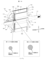
図3は、反負荷側から見たロータ110の分解斜視図である。図4は、負荷側から見たロータ110の分解斜視図である。図5Aは、第1端板及び第3端板を、第2端板及び第4端板側と対面する側から見た平面図である。図5Bは、第1端板及び第3端板を、ロータコアと対面する側から見た平面図である。図6は、ロータを軸方向と直交する方向に切断した断面図である。
FIG. 3 is an exploded perspective view of the
ロータ110は、複数の鋼板が積層されて構成されたロータコア112と、ロータコア112の一方の軸方向端部(反負荷側)に配置された第1端板113と、第1端板113の一方の軸方向外側(反負荷側)に配置された第2端板114と、ロータコア112の他方の軸方向端部(負荷側)に配置された第3端板115と、第3端板115の他方の軸方向外側(負荷側)に配置された第4端板116とを備えている。第1端板113は、第2端板114とロータコア112とにより挟まれるように配置され、第3端板115は、第4端板116とロータコア112とにより挟まれるように配置されている。
The
ロータシャフト111の外周面には、シャフト流路120と連通する第1シャフト流路孔121と、シャフト流路120と連通すると共に第1シャフト流路孔121に隣接して配置された第2シャフト流路孔122と、シャフト流路120と連通する第3シャフト流路孔123と、シャフト流路120と連通すると共に第3シャフト流路孔123に隣接して配置された第4シャフト流路孔124とが備えられている。
On the outer peripheral surface of the
第1シャフト流路孔121と第2シャフト流路孔122は、ロータシャフト111の周方向において同じ位置に配置されており、第3シャフト流路孔123と第4シャフト流路孔124は、ロータシャフト111の周方向において同じ位置に配置されている。第1シャフト流路孔121(第2シャフト流路孔122)と第3シャフト流路孔123(第4シャフト流路孔124)は、ロータシャフト111の周方向においてずらして配置されている。また、第1シャフト流路孔121~第4シャフト流路孔124は、ロータシャフト111の周方向において複数備えられている。
The first
第1端板113の中央部には、ロータシャフト111が挿入される軸方向に貫通した挿入孔113aが形成されている。
An
第1端板113の外側(第2端板114側)の面には、挿入孔113aから径方向外側に向かって放射状に伸びた複数の第1溝部131が形成されている。
A plurality of
第1端板113の内側(ロータコア112側)の面には、挿入孔113aから径方向外側に向かって放射状に伸びた複数の第2溝部132が形成されている。
A plurality of
また、第1端板113には、径方向外側に向かって突出した複数の突出部113bが形成されている。第1端板113の内側(ロータコア112側)の突出部113bの面には、径方向外側に向かって放射状に伸びた複数の第6溝部136が形成されている。
Further, the
第1端板113はロータシャフト111に形成された第1シャフト流路孔121と第2シャフト流路孔122と重なる位置に配置される。そして、第1溝部131は第1シャフト流路孔121と連通させ、第2溝部132は第2シャフト流路孔122と連通させる。
The
第1端板113が第2端板114に接すると、第1溝部131が覆われ、冷媒が流れる第1流路131aが形成される。すなわち、第1溝部131は、第1端板113と第2端板114とによって挟まれて形成される。第1流路131aは、径方向において挿入孔113aから径方向外側まで貫通するように形成されている。
When the
第1端板113がロータコア112に接すると、第2溝部132が覆われ、冷媒が流れる反負荷側第2流路132a(第2流路)が形成される。また、第1端板113がロータコア112に接すると、第6溝部136が覆われ、冷媒が流れる反負荷側第4流路136a(第4流路)が形成される。すなわち、第2流路の一部である反負荷側第2流路132aと、第4流路の一部である反負荷側第4流路136aは、第1端板113とロータコア112とによって挟まれて形成される。
When the
反負荷側第2流路132a(第2流路)は、径方向内側が挿入孔113aと貫通しているが、径方向外側は堰止め部132sで堰き止められている(図5B)。そして、反負荷側第2流路132a(第2流路)の径方向外側端部132eは、ロータコア流路130と接続される。また、反負荷側第4流路136a(第4流路)は、径方向外側が貫通しているが、径方向内側は堰き止められている。そして、反負荷側第4流路136a(第4流路)の径方向内側端部136eはロータコア流路130と接続される。
The anti-load side second flow
第2端板114には、ロータシャフト111が挿入される挿入孔114aと、第1流路131aの第1吐出口となる切欠き部114bと、突出部113bが嵌合すると共に、第4吐出口となる嵌合切欠き部114cが形成されている。
In the
本実施例では、第1端板113、第2端板114、ロータコア112を組合わせことにより、第1流路131a、反負荷側第2流路132a(第2流路)、反負荷側第4流路136a(第4流路)が形成され、これらをロータシャフト111と組み合わせることにより、第1流路131aと第1シャフト流路孔121とが連通し、反負荷側第2流路132a(第2流路)と第2シャフト流路孔122が連通する。
In this embodiment, by combining the
第3端板115の中央部には、ロータシャフト111が挿入される軸方向に貫通した挿入孔115aが形成されている。
An
第3端板115の外側(第4端板116側)の面には、挿入孔115aから径方向外側に向かって放射状に伸びた複数の第3溝部133が形成されている。
A plurality of
第3端板115の内側(ロータコア112側)の面には、挿入孔115aから径方向外側に向かって放射状に伸びた複数の第4溝部134が形成されている。
A plurality of
また、第3端板115には、径方向外側に向かって突出した複数の突出部115bが形成されている。第3端板115の内側(ロータコア112側)の突出部115bの面には、径方向外側に向かって放射状に伸びた複数の第5溝部135が形成されている。
Further, the
第3端板115はロータシャフト111に形成された第3シャフト流路孔123と第4シャフト流路孔124と重なる位置に配置される。そして、第3溝部133は第3シャフト流路孔123と連通させ、第4溝部134は第4シャフト流路孔124と連通させる。
The
第3端板115が第4端板116に接すると、第3溝部133が覆われ、冷媒が流れる第3流路133aが形成される。すなわち、第3溝部133は、第3端板115と第4端板116とによって挟まれて形成される。第3流路133aは、径方向において挿入孔113aから径方向外側まで貫通するように形成されている。
When the
第3端板115がロータコア112に接すると、第4溝部134が覆われ、冷媒が流れる負荷側第4流路134a(第4流路)が形成される。また、第3端板115がロータコア112に接すると、第5溝部135が覆われ、冷媒が流れる負荷側第2流路135a(第2流路)が形成される。すなわち、第4流路の一部である負荷側第4流路134aと、第2流路の一部である負荷側第2流路135aは、第3端板115とロータコア112とによって挟まれて形成される。
When the
負荷側第4流路134a(第4流路)は、径方向内側が挿入孔115aと貫通しているが、径方向外側は堰止め部134sで堰き止められている(図5B)。そして、負荷側第4流路134a(第2流路)の径方向外側端部134eは、ロータコア流路130と接続される。また、負荷側第2流路135a(第2流路)は、径方向外側が貫通しているが、径方向内側は堰き止められている。そして、負荷側第2流路135a(第2流路)の径方向内側端部135eはロータコア流路130と接続される。
The load-side
第4端板116には、ロータシャフト111が挿入される挿入孔116aと、第3流路133aの第3吐出口となる切欠き部116bと、突出部115bが嵌合すると共に、第2吐出口となる嵌合切欠き部116cが形成されている。
In the
本実施例では、第3端板115、第4端板116、ロータコア112を組合わせることにより、第3流路133aと負荷側第4流路134a(第4流路)が形成され、これらをロータシャフト111と組み合わせることにより、第3流路133aと第3シャフト流路孔123とが連通し、負荷側第4流路134a(第4流路)と第4シャフト流路孔124が連通する。
In this embodiment, by combining the
また、本実施例は、第1流路および第2流路のシャフト流路120との接続部は、ロータシャフト111の一方にあり、第3流路および第4流路のシャフト流路120との接続部は、ロータシャフト111の他方にある。
Further, in this embodiment, the connection portions of the first flow path and the second flow path with the
次にロータコア112について図3~図6を用いて説明する。ロータコア112には、複数の永久磁石117(磁石)が配置されている。永久磁石117は、周方向においてN極とS極が交互に配置されている。また、1つの極に配置される永久磁石117は分割されている。
Next, the
ロータコア112には、ロータシャフト111が挿入される軸方向に貫通した挿入孔112aと、冷媒が流れる第2流路及び第4流路の一部を構成する軸方向に貫通した複数のロータコア流路130(ロータコア流路130a~130h)が形成されている。複数のロータコア流路130a~130hは、磁極対称性若しくは磁極対対称性を保つように配置されている。本実施例では、複数のロータコア流路130a~130hは、周方向において45°の間隔で配置されている。本実施例によれば、第2流路、第4流路を構成する複数のロータコア流路130a~130hを、磁極対称性若しくは磁極対対称性を保つように配置しているので、力行と回生でモータ特性に差異が出ることを抑制することができる。
The
複数のロータコア流路130のうち、ロータコア流路130a~130dはそれぞれ、第1端板113に形成された径方向外側端部132eの位置において反負荷側第2流路132a(第2流路)と連通し、ロータコア流路130e~130hはそれぞれ第1端板113に形成された径方向内側端部136eの位置において反負荷側第4流路136a(第4流路)と連通している。すなわち、ロータコア流路130a~130dは第2流路となり、ロータコア流路130e~130hは第4流路となる
また、複数のロータコア流路130のうち、ロータコア流路130a~130dはそれぞれ、第3端板115に形成された径方向内側端部135eの位置において負荷側第2流路135a(第2流路)と連通し、ロータコア流路130e~130hはそれぞれ第3端板115に形成された径方向外側端部134eの位置において負荷側第4流路134a(第4流路)と連通している。
Among the plurality of rotor core flow passages 130, rotor
本実施例の第2流路は、反負荷側第2流路132aによってロータシャフト111の径方向外側に延在してロータコア流路130a~130dに接続し、ロータコア流路130a~130dによってロータコア112の内部を軸方向に延在した後、負荷側第2流路135aに接続し径方向外側に延在すると共に径方向外側に向かって開口した第2吐出口を有している。
The second flow path of this embodiment extends radially outward of the
同様に、本実施例の第4流路は、負荷側第4流路134aによってロータシャフト111の径方向外側に延在してロータコア流路130e~130hに接続し、ロータコア流路130e~130hによってロータコア112の内部を軸方向に延在した後、反負荷側第4流路136aに接続し径方向外側に延在すると共に径方向外側に向かって開口した第4吐出口を有している。
Similarly, the fourth flow path of this embodiment extends radially outward of the
次に、ロータ110における冷媒の流れについて説明する。図7は、本発明の実施例1に係るロータ110を軸方向に沿って切断した断面斜視図である。図8は、ロータ110を軸方向に沿って切断した上半分の断面図である。
Next, the flow of refrigerant in
ロータシャフト111は、軸方向の一端(反負荷側)が開口し、他端(負荷側)が中実となっている。ロータシャフト111の一端の開口には、オイルクーラー4を介して冷媒ポンプ8が接続される(図2)。ロータ110が回転すると、シャフト流路120に流入した冷媒の一部は、第1シャフト流路孔121、第2シャフト流路孔122から吐出される。
The
第1シャフト流路孔121から径方向外側に向かって吐出された冷媒は、第1流路131aを通り、切欠き部114b(第1吐出口)から吐出される。切欠き部114bから吐出された冷媒は、ステータコイル141に当たり、ステータコイル141を冷却する。
The refrigerant discharged radially outward from the first
第2シャフト流路孔122から径方向外側に向かって吐出された冷媒は、第2流路を形成する反負荷側第2流路132a、ロータコア流路130(130a,130c,130e,130g)、負荷側第2流路135aを通り、嵌合切欠き部116c(第2吐出口)から吐出される。嵌合切欠き部116cから吐出された冷媒は、ステータコイル141に当たり、ステータコイル141を冷却する。また、第2流路を流れる冷媒は、ロータコア112の内部を流れるので、ロータコア112に配置された永久磁石117を冷却する。
The refrigerant discharged radially outward from the second shaft flow path hole 122 includes an anti-load side second flow
同様に、第3シャフト流路孔123から径方向外側に向かって吐出された冷媒は、第3流路133aを通り、切欠き部116b(第3吐出口)から吐出される。切欠き部116bから吐出された冷媒は、ステータコイル141に当たり、ステータコイル141を冷却する。
Similarly, the refrigerant discharged radially outward from the third
第4シャフト流路孔124から径方向外側に向かって吐出された冷媒は、第4流路を形成する負荷側第4流路134a、ロータコア流路130(130b,130d,130f,130h)、反負荷側第4流路136aを通り、嵌合切欠き部114c(第4吐出口)から吐出される。嵌合切欠き部114cから吐出された冷媒は、ステータコイル141に当たり、ステータコイル141を冷却する。また、第4流路を流れる冷媒は、ロータコア112の内部を流れるので、ロータコア112に配置された永久磁石117を冷却する。
The refrigerant discharged radially outward from the fourth
第2流路を形成するロータコア流路130a~130dの流れと、第4流路形成するロータコア流路130e~130hとは、軸方向流れが対向し、周方向において互い違いになるように配置されている。
The flow in the rotor
第1流路と第2流路、第3流路と第4流路は、それぞれ周方向に等間隔に複数(4つずつ)配置されている。また、第1流路と第2流路の数は、軸方向の一方と他方で同一であり、第3流路と第4流路の数は、軸方向の他方と一方で同一である。 A plurality of first channels, a second channel, and a plurality of third channels and fourth channels are arranged at equal intervals in the circumferential direction (four each). Further, the numbers of the first flow passages and the second flow passages are the same on one side and the other side in the axial direction, and the numbers of the third flow passages and the fourth flow passages are the same on one side and the other side in the axial direction.
さらに、本実施例では、第1流路と第3流路は、軸方向から見て重ならないように配置し、周方向において45°ずらして配置している。同様に第2流路と第4流路は、軸方向から見て重ならないように配置し、周方向において45°ずらして配置している。このように配置することにより、ロータの周方向の重量バランスを均一化することができ、ロータ回転時の偏心を抑制することができる。 Furthermore, in this embodiment, the first flow path and the third flow path are arranged so as not to overlap when viewed from the axial direction, and are arranged at a 45° offset in the circumferential direction. Similarly, the second flow path and the fourth flow path are arranged so as not to overlap when viewed from the axial direction, and are arranged at a 45° offset in the circumferential direction. By arranging the rotor in this manner, the weight balance in the circumferential direction of the rotor can be made uniform, and eccentricity during rotation of the rotor can be suppressed.
車両等の駆動用として使用される回転電機は負荷に応じて回転数が変化する。低速回転時には大きなモータトルクが必要となるためステータコイルに流れる電流が大きくなり、ステータコイルの発熱量が増加する。一方、高速回転時には渦電流損失が増加し永久磁石の温度が上昇する。すなわち、回転電機は、低速回転時には主にステータコイルを冷却し、高速回転時には主に永久磁石を冷却することが好ましい。 The rotational speed of a rotating electrical machine used to drive a vehicle or the like changes depending on the load. Since a large motor torque is required during low speed rotation, the current flowing through the stator coil increases, and the amount of heat generated by the stator coil increases. On the other hand, during high-speed rotation, eddy current loss increases and the temperature of the permanent magnet increases. That is, it is preferable that the rotating electrical machine mainly cools the stator coil during low-speed rotation, and mainly cools the permanent magnets during high-speed rotation.
本実施例では、第2流路の吐出口となる嵌合切欠き部116c(第2吐出口)が第1流路の吐出口となる切欠き部114b(第1吐出口)よりも径方向外側に配置されている。すなわち、嵌合切欠き部116c(第2吐出口)の吐出位置γ02は、切欠き部114b(第1吐出口)の吐出位置γ01より大きい(γ02>γ01)。
In this embodiment, the
本実施例では、嵌合切欠き部116c(第2吐出口)は切欠き部114b(第1吐出口)よりも径方向外側に配置されているので、第1流路に比べ第2流路の流路抵抗が大きくなる。ロータ110を回転させると、流路が冷媒で満たされ、切欠き部114b(第1吐出口)と嵌合切欠き部116c(第2吐出口)から冷媒が吐出されるが、ロータ110の回転数が低い場合(低速回転)には、ロータ110の回転による遠心力が小さいので、流路抵抗が小さい切欠き部114b(第1吐出口)からの冷媒吐出量が増加する。
In this embodiment, the
一方、ロータ110の回転数が高い場合(高速回転)には、切欠き部114b(第1吐出口)よりも径方向外側に配置されている嵌合切欠き部116c(第2吐出口)での冷媒に働く遠心力が大きくなるので、第1流路を流れる冷媒よりも第2流路(反負荷側第2流路132a、ロータコア流路130a~130e、負荷側第2流路135a)を流れる冷媒が増加する。
On the other hand, when the rotation speed of the
図9は、回転数の変化に応じた第1流路と第2流路の流量の関係を示す図である。図9において、第1流路の吐出量と第2流路の吐出量の合計が全体の吐出量となる。図9に示すように、回転数が増加すると第1流路からの吐出量が減少する。一方、回転数が増加すると第2流路からの吐出量が増加する。このように、本実施例では、回転数に応じて第1流路と第2流路からの吐出量が変化する。 FIG. 9 is a diagram showing the relationship between the flow rates of the first flow path and the second flow path according to changes in the rotation speed. In FIG. 9, the total discharge amount is the sum of the discharge amount of the first flow path and the discharge amount of the second flow path. As shown in FIG. 9, as the rotational speed increases, the discharge amount from the first flow path decreases. On the other hand, as the rotational speed increases, the amount of discharge from the second flow path increases. In this way, in this embodiment, the discharge amount from the first flow path and the second flow path changes depending on the rotation speed.
本実施例によれば、ロータの回転数が低い場合には、第1流路を流れる冷媒を多くし発熱量が大きくなるステータコイルを主に冷却でき、ロータの回転数が高い場合には、第2流路を流れる冷媒を多くし渦電流損失増加によって温度上昇する永久磁石を主に冷却することができる。 According to this embodiment, when the rotation speed of the rotor is low, the refrigerant flowing through the first flow path can be increased to mainly cool the stator coil, which generates a large amount of heat, and when the rotation speed of the rotor is high, By increasing the amount of refrigerant flowing through the second flow path, it is possible to mainly cool the permanent magnet whose temperature increases due to increased eddy current loss.
また、本実施例によれば、第1流路と第2流路はそれぞれ独立してシャフト流路120と連通するようにしているので、第2流路の冷媒に働く遠心力による遠心ポンプ効果が第2流路のみに働くため、高速回転時の遠心ポンプ効果による第2流路の流量増加を一層向上することができる。
Further, according to this embodiment, since the first flow path and the second flow path are each independently communicated with the
なお、説明は省略するが、切欠き部(第3吐出口)116bと嵌合切欠き部(第4吐出口)114cの関係についても、切欠き部114b(第1吐出口)と嵌合切欠き部116c(第2吐出口)の関係と同じである。
Although the description is omitted, the relationship between the notch portion (third discharge port) 116b and the fitting notch portion (fourth discharge port) 114c is also similar to that between the
本発明の実施例2について図10を用いて説明する。実施例1と共通する構成については同じ符号を付し、その詳細な説明は省略する。図10は、本発明の実施例2に係るロータを軸方向と直交する方向に切断した断面図である。 Example 2 of the present invention will be described using FIG. 10. Components that are common to those in the first embodiment are given the same reference numerals, and detailed description thereof will be omitted. FIG. 10 is a cross-sectional view of a rotor according to a second embodiment of the present invention, taken in a direction perpendicular to the axial direction.
実施例1では、複数のロータコア流路130a~130hが磁極対称性若しくは磁極対対称性を保つように配置したが、実施例2では、複数のロータコア流路130a~130hが磁極対称性若しくは磁極対対称性を保たないように配置している。
In the first embodiment, the plurality of rotor
本実施例によれば、第2流路を構成するロータコア流路130a~130d、第4流路を構成するロータコア流路130e~130hが磁極対称性もしくは磁極対対称性を保たないように設けることで、ロータ形状の対称性に対応する円環振動モードの振幅を小さくでき、振動・騒音を抑制することができる。
According to this embodiment, the rotor
本発明の実施例3について図11を用いて説明する。実施例1と共通する構成については同じ符号を付し、その詳細な説明は省略する。図11は、本発明の実施例3に係るロータ110を軸方向に沿って切断した上半分の断面図である。
Example 3 of the present invention will be described using FIG. 11. Components that are common to those in the first embodiment are given the same reference numerals, and detailed description thereof will be omitted. FIG. 11 is a cross-sectional view of the upper half of the
実施例1では、第1流路と反負荷側第2流路132a(第2流路)はそれぞれ独立させてシャフト流路120に連通させるようにしていたが、実施例3では、第1流路と反負荷側第2流路132a(第2流路)のシャフト流路120への接続部を共有している。
In the first embodiment, the first flow path and the second counter-load
ロータシャフト111の外周面には、シャフト流路120と連通する第2シャフト流路孔122と、シャフト流路120と連通する第4シャフト流路孔124とが備えられている。反負荷側第2流路132a(第2流路)と第2シャフト流路孔122が連通する。
The outer peripheral surface of the
反負荷側第2流路132a(第2流路)には、分岐流路137の一端が接続されており、分岐流路137の他端が第1流路131aに接続されている。
One end of a
第2シャフト流路孔122から吐出した冷媒は、反負荷側第2流路132a(第2流路)を流れると共に、分岐流路137で分岐されて第1流路131aに流入し第1流路131aを流れる。以降の冷媒の流れは実施例1と同様であるので説明は省略する。
The refrigerant discharged from the second shaft flow path hole 122 flows through the
本実施例によれば、第1流路と第2流路のシャフト流路への連通部を共有化しているので、流路構造を簡略できる。 According to this embodiment, since the first flow path and the second flow path share a communication portion with the shaft flow path, the flow path structure can be simplified.
なお、説明は省略するが第3流路と第4流路のシャフト流路への接続も同様であり、シャフト流路への連通部を共有化している。 Note that, although the explanation will be omitted, the connection of the third flow path and the fourth flow path to the shaft flow path is also the same, and the communication portion to the shaft flow path is shared.
本発明の実施例4について図12を用いて説明する。実施例1と共通する構成については同じ符号を付し、その詳細な説明は省略する。図12は、本発明の実施例4に係るロータ110を軸方向に沿って切断した断面斜視図である。
Example 4 of the present invention will be described using FIG. 12. Components that are common to those in the first embodiment are given the same reference numerals, and detailed description thereof will be omitted. FIG. 12 is a cross-sectional perspective view taken along the axial direction of the
実施例4では、第2流路を形成する反負荷側第2流路132aと負荷側第2流路135aの流路断面積を異ならせている。第2流路の上流側に位置する反負荷側第2流路132aの流路断面積(上流側流路断面積Su)は、下流側に位置する負荷側第2流路135aの流路断面積(下流側流路断面積Sd)以上としている。
In Example 4, the cross-sectional areas of the anti-load side second flow
本実施例によれば、流路断面積を上流側より下流側の方が小さくすることによって、流路内部へ吐出口から大気が侵入することにより冷媒に働く遠心力が作る圧力差が減少することを抑制できるため、高速回転時の第2流路の流量増加効果をより一層向上することができる。 According to this embodiment, by making the cross-sectional area of the flow path smaller on the downstream side than on the upstream side, air enters the inside of the flow path from the discharge port, thereby reducing the pressure difference created by the centrifugal force acting on the refrigerant. Since this can be suppressed, the effect of increasing the flow rate of the second flow path during high-speed rotation can be further improved.
なお、本実施例では、第2流路について説明したが、第1流路、第3流路、第4流路についても同様に構成しても良い。 Although the second flow path has been described in this embodiment, the first flow path, third flow path, and fourth flow path may be configured in the same manner.
本発明の実施例5について図13を用いて説明する。実施例1と共通する構成については同じ符号を付し、その詳細な説明は省略する。図13は、本発明の実施例5に係るロータ110を軸方向に沿って切断した断面斜視図である。
Example 5 of the present invention will be described using FIG. 13. Components that are common to those in the first embodiment are given the same reference numerals, and detailed description thereof will be omitted. FIG. 13 is a cross-sectional perspective view taken along the axial direction of a
実施例5では、第1流路131aと、第2流路を形成する反負荷側第2流路132aの流路断面積を異ならせている。第1流路131aの流路断面積S1は、第2流路の上流側に位置する反負荷側第2流路132aの流路断面積(第2流路の断面積S2)以上としている。
In the fifth embodiment, the cross-sectional area of the
本実施例によれば、第1流路の流路断面積を第2流路の流路断面積以上にすることによって、第1流路の流路抵抗を小さくし、低速回転時の第1流路の流量比を増大できるため、低速回転時のステータコイルの冷却性能を向上することができる。 According to this embodiment, by making the cross-sectional area of the first flow path greater than or equal to the cross-sectional area of the second flow path, the flow resistance of the first flow path is reduced, and the Since the flow rate ratio of the flow path can be increased, the cooling performance of the stator coil during low speed rotation can be improved.
本発明の実施例6について図14を用いて説明する。実施例1と共通する構成については同じ符号を付し、その詳細な説明は省略する。図14は、本発明の実施例6に係るロータ110を軸方向に沿って切断した断面斜視図である。
Example 6 of the present invention will be described using FIG. 14. Components that are common to those in the first embodiment are given the same reference numerals, and detailed description thereof will be omitted. FIG. 14 is a cross-sectional perspective view taken along the axial direction of a
実施例6では、第1シャフト流路孔121と、第2シャフト流路孔122の断面積を異ならせている。第1シャフト流路孔121の断面積Si1は、第2シャフト流路孔122の断面積Si2以下としている。
In the sixth embodiment, the first
本実施例によれば、第1流路の入口断面積を第2流路の入口断面積より小さくすることで、高速回転時に主要な圧力損失となる入口圧力損失を第1流路より第2流路の方が小さくすることができるため、高速回転時の第2の流路の流量比を増大することができる。 According to this embodiment, by making the inlet cross-sectional area of the first flow path smaller than the inlet cross-sectional area of the second flow path, the inlet pressure loss, which is the main pressure loss during high-speed rotation, is reduced from the first flow path to the second flow path. Since the flow path can be made smaller, the flow rate ratio of the second flow path during high-speed rotation can be increased.
なお、本発明は、上述した実施例に限定するものではなく、様々な変形例が含まれる。上述した実施例は本発明を分かり易く説明するために詳細に説明したものであり、必ずしも説明した全ての構成を備えるものに限定するものではない。 Note that the present invention is not limited to the embodiments described above, and includes various modifications. The embodiments described above are described in detail to explain the present invention in an easy-to-understand manner, and the present invention is not necessarily limited to those having all the configurations described.
1…車体、2…車輪、3…車両駆動装置、4…オイルクーラー、5…配管、6…チラー、7…配管、8…冷媒ポンプ、100…回転電機、101…ハウジング、110…ロータ、111…ロータシャフト、112…ロータコア、113…第1端板、113a…挿入孔、114…第2端板、114a…挿入孔、114b…切欠き部(第1吐出口)、114c…嵌合切欠き部(第4吐出口)、115…第3端板、115a…挿入孔、115b…突出部、116…第4端板、116a…挿入孔、116b…切欠き部(第3吐出口)、116c…嵌合切欠き部(第2吐出口)、117…永久磁石、120…シャフト流路、121…第1シャフト流路孔、122…第2シャフト流路孔、123…第3シャフト流路孔、124…第4シャフト流路孔、130,130a~130h…ロータコア流路、131…第1溝部、131a…第1流路、132…第2溝部、132a…反負荷側第2流路(第2流路)、132s…堰止め部、132e…径方向外側端部、133…第3溝部、133a…第3流路、134…第4溝部、134a…負荷側第4流路(第4流路)、134s…堰止め部、134e…径方向外側端部、135…第5溝部
135a…負荷側第2流路(第2流路)、135e…径方向内側端部、136…第6溝部、136a…反負荷側第4流路(第4流路)、136e…径方向内側端部、137…分岐流路、140…ステータ、141…スタータコイル、150,151,152…軸受、154…オイルパン、200…減速機、201…駆動キヤ、202…従動ギヤ、203…従動ギヤシャフト、204,205…軸受
DESCRIPTION OF SYMBOLS 1... Vehicle body, 2... Wheel, 3... Vehicle drive system, 4... Oil cooler, 5... Piping, 6... Chiller, 7... Piping, 8... Refrigerant pump, 100... Rotating electric machine, 101... Housing, 110... Rotor, 111 ...Rotor shaft, 112...Rotor core, 113...First end plate, 113a...Insertion hole, 114...Second end plate, 114a...Insertion hole, 114b...Notch (first discharge port), 114c...Fitting notch (fourth outlet), 115... third end plate, 115a... insertion hole, 115b... protrusion, 116... fourth end plate, 116a... insertion hole, 116b... notch (third outlet), 116c... Fitting notch (second discharge port), 117... Permanent magnet, 120... Shaft channel, 121... First shaft channel hole, 122... Second shaft channel hole, 123... Third shaft channel hole, 124 ... Fourth shaft passage hole, 130, 130a to 130h... Rotor core passage, 131... First groove, 131a... First passage, 132... Second groove, 132a... Counter-load side second passage (
Claims (16)
前記ロータの内周側にはロータシャフトが設けられ、前記ロータシャフトの内部には冷媒が流通するシャフト流路が設けられ、
前記ロータは、
前記ロータシャフトの径方向外側に延在すると共に径方向外側に向かって開口した第1吐出口を有する第1流路と、
前記ロータシャフトの径方向外側に延在し、前記ロータコアの内部を軸方向に延在した後、径方向外側に延在すると共に径方向外側に向かって開口した第2吐出口を有する第2流路と、を有し、
前記第1流路と前記第2流路は前記シャフト流路に接続され、
前記第2吐出口は、前記第1吐出口よりも径方向外側に配置されたことを特徴とする回転電機。 A rotating electric machine comprising a rotor in which a magnet is disposed in a rotor core, and a stator disposed on an outer diameter side of the rotor,
A rotor shaft is provided on the inner peripheral side of the rotor, and a shaft flow path through which a refrigerant flows is provided inside the rotor shaft,
The rotor is
a first flow path extending radially outward of the rotor shaft and having a first discharge port opening radially outward;
a second flow extending radially outwardly of the rotor shaft, extending axially inside the rotor core, and having a second discharge port extending radially outwardly and opening radially outwardly; has a road and a
the first flow path and the second flow path are connected to the shaft flow path;
The rotating electric machine, wherein the second discharge port is arranged radially outward from the first discharge port.
前記第1流路および前記第2流路はそれぞれ周方向に等間隔に複数備えられたことを特徴とする回転電機。 In claim 1,
A rotating electric machine characterized in that a plurality of the first flow passages and the second flow passages are provided at equal intervals in the circumferential direction.
前記第1流路および前記第2流路の数は同一であることを特徴とする回転電機。 In claim 1,
A rotating electric machine, wherein the first flow path and the second flow path are the same in number.
前記ロータは、
前記ロータシャフトの径方向外側に延在すると共に径方向外側に向かって開口した第3吐出口を有する第3流路と、
前記ロータコアの内部を軸方向に延在した後、径方向外側に延在すると共に径方向外側に向かって開口した第4吐出口を有する第4流路と、を有し、
前記第3流路と前記第4流路は前記シャフト流路に接続され、
前記第4吐出口は、前記第3吐出口よりも径方向外側に設けられ、
前記第1流路および前記第2流路の前記シャフト流路との接続部は、前記ロータシャフトの一方にあり、前記第3流路および前記第4流路の前記シャフト流路との接続部は、前記ロータシャフトの他方にあることを特徴とする回転電機。 In claim 1,
The rotor is
a third flow path extending radially outwardly of the rotor shaft and having a third outlet opening radially outwardly;
a fourth flow path extending axially inside the rotor core, extending radially outward, and having a fourth outlet opening radially outward;
The third flow path and the fourth flow path are connected to the shaft flow path,
The fourth discharge port is provided radially outward from the third discharge port,
Connection portions of the first flow path and the second flow path with the shaft flow path are located on one side of the rotor shaft, and connection portions of the third flow path and the fourth flow path with the shaft flow path are located on one side of the rotor shaft. is located on the other side of the rotor shaft.
前記第2流路の軸方向の流れ方向と、前記第4流路の軸方向の流れ方向は、互いが対向することを特徴とする回転電機。 In claim 4,
The rotating electrical machine is characterized in that the axial flow direction of the second flow path and the axial flow direction of the fourth flow path are opposite to each other.
前記第2流路は、磁極対称性もしくは磁極対対称性を保つように配置したことを特徴とする回転電機。 In claim 1,
A rotating electric machine, wherein the second flow path is arranged so as to maintain magnetic pole symmetry or magnetic pole pair symmetry.
前記第2流路は、磁極対称性もしくは磁極対対称性を保たないように配置したことを特徴とする回転電機。 In claim 1,
A rotating electrical machine, wherein the second flow path is arranged so as not to maintain magnetic pole symmetry or magnetic pole pair symmetry.
前記第1流路と前記第2流路は、それぞれ独立して前記シャフト流路と連通することを特徴とする回転電機。 In claim 1,
A rotating electrical machine, wherein the first flow path and the second flow path each independently communicate with the shaft flow path.
前記第1流路と前記第2流路は、前記シャフト流路への接続部を共有することを特徴とする回転電機。 In claim 1,
The rotating electric machine, wherein the first flow path and the second flow path share a connection portion to the shaft flow path.
前記第2流路の上流側流路断面積は下流側流路断面積以上としたことを特徴とする回転電機。 In claim 1,
A rotating electric machine characterized in that an upstream cross-sectional area of the second flow path is greater than or equal to a downstream cross-sectional area.
前記第1流路の流路断面積は、前記第2流路の流路断面積以上としたことを特徴とする回転電機。 In claim 1,
A rotating electric machine, wherein a cross-sectional area of the first flow path is greater than or equal to a cross-sectional area of the second flow path.
前記ロータシャフトには、前記第1流路と連通する第1シャフト流路孔と、前記第2流路と連通する第2シャフト流路孔が備えられ、
前記第1シャフト流路孔の断面積は、前記第2シャフト流路孔の断面積以下としたことを特徴とする回転電機。 In claim 1,
The rotor shaft is provided with a first shaft passage hole communicating with the first passage and a second shaft passage hole communicating with the second passage,
A rotating electric machine characterized in that a cross-sectional area of the first shaft passage hole is less than or equal to a cross-sectional area of the second shaft passage hole.
前記ロータコアの一方の軸方向外側に配置された第1端板と、前記第1端板の一方の軸方向外側に配置された第2端板とを備え、
前記第1流路および前記第2流路の一部は、前記第1端板と前記第2端板、前記第1端板と前記ロータコアとによって挟まれて形成されたことを特徴とする回転電機。 In claim 1,
a first end plate disposed on one axial outer side of the rotor core; and a second end plate disposed on one axial outer side of the first end plate,
A part of the first flow path and the second flow path are formed by being sandwiched between the first end plate and the second end plate, and the first end plate and the rotor core. Electric machine.
前記ロータシャフトは、軸方向の一端が開口し、他端が中実であることを特徴とする回転電機。 In claim 1,
A rotating electrical machine, wherein the rotor shaft is open at one end in the axial direction and solid at the other end.
前記ロータシャフトの一端の開口には、冷媒ポンプが接続されることを特徴とする回転電機。 In claim 14,
A rotating electric machine, wherein a refrigerant pump is connected to an opening at one end of the rotor shaft.
請求項1乃至15のいずれか1項に記載された回転電機を備えたことを特徴とする車両駆動装置。 A vehicle drive device that drives a vehicle,
A vehicle drive device comprising the rotating electric machine according to claim 1 .
Priority Applications (2)
| Application Number | Priority Date | Filing Date | Title |
|---|---|---|---|
| JP2022096714A JP2023183205A (en) | 2022-06-15 | 2022-06-15 | Rotary electric machine and vehicle driving device with the same |
| PCT/JP2023/008776 WO2023243161A1 (en) | 2022-06-15 | 2023-03-08 | Rotating electrical machine and vehicle drive device equipped with same |
Applications Claiming Priority (1)
| Application Number | Priority Date | Filing Date | Title |
|---|---|---|---|
| JP2022096714A JP2023183205A (en) | 2022-06-15 | 2022-06-15 | Rotary electric machine and vehicle driving device with the same |
Publications (1)
| Publication Number | Publication Date |
|---|---|
| JP2023183205A true JP2023183205A (en) | 2023-12-27 |
Family
ID=89192673
Family Applications (1)
| Application Number | Title | Priority Date | Filing Date |
|---|---|---|---|
| JP2022096714A Pending JP2023183205A (en) | 2022-06-15 | 2022-06-15 | Rotary electric machine and vehicle driving device with the same |
Country Status (2)
| Country | Link |
|---|---|
| JP (1) | JP2023183205A (en) |
| WO (1) | WO2023243161A1 (en) |
Family Cites Families (3)
| Publication number | Priority date | Publication date | Assignee | Title |
|---|---|---|---|---|
| JP5392101B2 (en) * | 2010-01-08 | 2014-01-22 | トヨタ自動車株式会社 | Motor cooling structure |
| JP2019187063A (en) * | 2018-04-09 | 2019-10-24 | 日産自動車株式会社 | Rotary electric machine |
| CN111884428B (en) * | 2020-06-28 | 2021-10-22 | 华为技术有限公司 | Motor, motor cooling system and electric vehicle |
-
2022
- 2022-06-15 JP JP2022096714A patent/JP2023183205A/en active Pending
-
2023
- 2023-03-08 WO PCT/JP2023/008776 patent/WO2023243161A1/en unknown
Also Published As
| Publication number | Publication date |
|---|---|
| WO2023243161A1 (en) | 2023-12-21 |
Similar Documents
| Publication | Publication Date | Title |
|---|---|---|
| JP5734765B2 (en) | Cooling structure of rotating electric machine | |
| JP4492745B2 (en) | Rotating electric machine | |
| JP2016073163A (en) | Operational method of rotary electric machine | |
| CN106100186A (en) | Electric rotating machine | |
| WO2013136405A1 (en) | Rotating electrical machine | |
| KR101303469B1 (en) | Cooling structure of generator motor, and generator motor | |
| JP2018014857A (en) | Cooling structure of electric motor | |
| US20200227978A1 (en) | Rotary electric machine | |
| JP6085267B2 (en) | Rotating electric machine | |
| CN115224879A (en) | Rotor cooling assembly and method for interior of permanent magnet motor | |
| JP2012095381A (en) | Cooling device for rotating electric machine for vehicle | |
| WO2023243161A1 (en) | Rotating electrical machine and vehicle drive device equipped with same | |
| JP2020162338A (en) | Rotary electric machine | |
| JP5710886B2 (en) | Rotating electric machine | |
| EP4246775A1 (en) | Rotor, motor, and electric vehicle | |
| CN215009955U (en) | Motor cooling structure and motor | |
| JP6332876B2 (en) | Rotating electric machine rotor and method of manufacturing rotating electric machine rotor | |
| JP3675363B2 (en) | Rotating electric machine | |
| CN102906971A (en) | Lubricating structure for generator motor, and generator motor | |
| KR20220045317A (en) | Oil recovery structure for cooling motor | |
| WO2023132093A1 (en) | Rotary electrical machine and vehicle driving device equipped with rotary electrical machine | |
| JP2020022232A (en) | Cooling structure for interior of stator core | |
| JP2019134573A (en) | Stator of rotary electric machine | |
| WO2024053058A1 (en) | Rotary electric machine | |
| JP7425023B2 (en) | motor |