JP2023166301A - Truck berth and working method - Google Patents
Truck berth and working method Download PDFInfo
- Publication number
- JP2023166301A JP2023166301A JP2022077274A JP2022077274A JP2023166301A JP 2023166301 A JP2023166301 A JP 2023166301A JP 2022077274 A JP2022077274 A JP 2022077274A JP 2022077274 A JP2022077274 A JP 2022077274A JP 2023166301 A JP2023166301 A JP 2023166301A
- Authority
- JP
- Japan
- Prior art keywords
- truck
- platform
- pair
- connecting means
- berth
- Prior art date
- Legal status (The legal status is an assumption and is not a legal conclusion. Google has not performed a legal analysis and makes no representation as to the accuracy of the status listed.)
- Pending
Links
Images

Landscapes
- Refuge Islands, Traffic Blockers, Or Guard Fence (AREA)
- Auxiliary Methods And Devices For Loading And Unloading (AREA)
Abstract
Description
本発明は、トラックの駐車スペースと荷物の積み降ろしエリアであるプラットフォームとを有するトラックバースの構造及びトラックバースにおける作業方法に関する。 The present invention relates to a structure of a truck berth having a parking space for trucks and a platform serving as a loading/unloading area for cargo, and a method of working at the truck berth.
一般に、トラックバースにおいて荷物の積み降ろしをする際、図22に示すように、トラック20の荷台開口部をプラットフォーム10側に向けて停車し、トラックのテールゲートリフター21を経由して荷物の積み降ろしを行う。 Generally, when loading and unloading cargo at a truck berth, as shown in FIG. I do.
このとき、荷物の積み降ろし作業の際にテールゲートリフターから作業者や荷物が転落する事故が数多く発生している。この問題に対して、たとえば、厚生労働省ではテールゲートリフターに転落防止用の安全柵を設けること(以下、「安全柵方式」ともいう。)を推奨している。(非特許文献1参照。)
At this time, many accidents occur in which workers and cargo fall from the tailgate lifter during loading and unloading operations. To address this problem, the Ministry of Health, Labor and Welfare, for example, recommends installing a safety fence on the tailgate lifter to prevent falls (hereinafter also referred to as the "safety fence method"). (See Non-Patent
また、特許文献1では、プラットフォーム側にテールゲートリフターを収容する空間を設けたT字型構造体が提案されている。
Further,
しかしながら、非特許文献1の技術では、テールゲートリフターとプラットフォームとの間に安全柵の無い隙間が生じるため、テールゲートリフターからプラットフォームへ移る際に、その隙間から足を踏み外したり転落したりする危険性がある。また、テールゲートリフターに安全柵を装備していないトラックについては従来と同様の危険性が存在する。一方、特許文献1の技術は、プラットフォーム下部にテールゲートリフターを収納して、トラック荷台開口部をプラットフォームに近接させて荷物の積み降ろしをするため非特許文献1に記載のテールゲートリフターに安全柵を設ける方法に比べて、より安全な作業が期待できるものの、T字型構造体を構築する必要があるためコストがかかる。
However, in the technology of Non-Patent
本発明はかかる従来の事情に対処してなされたものであり、倉庫での荷物の積み降ろし作業の際に、トラックのテールゲートリフターやプラットフォームからの転落を効果的に防止して、より安全な作業を低コストで実現することのできるトラックバース及び作業方法を提供することを目的とする。 The present invention was made in response to such conventional circumstances, and effectively prevents falls from the tailgate lifter or platform of a truck during loading and unloading work in a warehouse, thereby making it safer. It is an object of the present invention to provide a truck berth and a working method that can realize work at low cost.
上記目的を達成するため、本発明に係るトラックバースは、トラックの荷台から荷物の積み降ろしを行うプラットフォームを有するトラックバースであって、
前記プラットフォームの側面に沿って取り付けられた一対の支柱を備え、
当該一対の支柱の夫々は、前記トラックの荷台内部の両側面上に水平方向に延設されたレールの掛止穴と夫々連結手段によって連結させるための掛止穴を有し、前記トラックの着車位置に該トラックの荷台の幅と略同一の間隔で前記プラットフォームの上面から夫々鉛直方向に延出していることを特徴とする。
In order to achieve the above object, a truck berth according to the present invention is a truck berth having a platform for loading and unloading cargo from the bed of a truck, comprising:
a pair of struts attached along the sides of the platform;
Each of the pair of supports has a latching hole for connecting with a latching hole of a rail extending horizontally on both sides of the inside of the loading bed of the truck, and the latching hole is connected to the latching hole of a rail extending horizontally on both sides of the inside of the loading bed of the truck. It is characterized by extending vertically from the upper surface of the platform at intervals substantially equal to the width of the truck bed at the vehicle position.
本発明では、トラックの荷台両側面のレールとプラットフォーム側とを直接連結手段(例えばベルト)で繋ぐための支柱をプラットフォーム側に設ける。これにより、テールゲートリフターに安全柵を備えないトラックに対しても安全に荷物の積み降ろし作業ができるトラックバースを提供することができる。特にテールゲートリフターの安全柵では、プラットフォームに荷物を移動させる際に、テールゲートリフターからプラットフォームへ移るタイミングで安全柵によるガードが無くなるので、所謂回り込みによる転落事故が発生する可能性がある。これを回避するためには、テールゲートリフターがプラットフォームに十分に近接するようにトラックを駐車させる必要がある。また、如何に近接させても、回り込みの転落事故を防止することが困難であるが、本発明では、プラットフォーム側支柱とトラック荷台との間で連結手段(ベルト)を張るので、安全柵方式に比べてトラック駐車時の駐車位置の精度は要求されず、また回り込みによる転落事故の発生を低減させることができる。 In the present invention, struts are provided on the platform side for directly connecting the rails on both sides of the truck bed and the platform side using a connecting means (for example, a belt). Thereby, it is possible to provide a truck berth that allows cargo to be safely loaded and unloaded even for trucks that do not have a safety fence on the tailgate lifter. In particular, with the safety fence of the tailgate lifter, when moving cargo to the platform, the guard by the safety fence is lost at the timing of moving from the tailgate lifter to the platform, so there is a possibility of a fall accident due to so-called detouring. To avoid this, the truck must be parked so that the tailgate lifter is close enough to the platform. In addition, no matter how close they are, it is difficult to prevent falling accidents due to detours, but in the present invention, a connecting means (belt) is stretched between the platform side support and the truck bed, so a safety fence method is not possible. In comparison, when parking a truck, the accuracy of the parking position is not required, and the occurrence of falling accidents due to detours can be reduced.
また本発明では、前記プラットフォームの側面には、上面が前記プラットフォームの上面と略面一になるように、前記トラックのテールゲートリフターの左右両端を夫々着座させるための突起部を備え、
前記一対の支柱は、夫々前記突起部の外側両側面と前記プラットフォームの側面とで形成される角部に取り付けられていることを特徴とする。
Further, in the present invention, the side surface of the platform is provided with protrusions for seating both left and right ends of the tailgate lifter of the truck, respectively, so that the upper surface is substantially flush with the upper surface of the platform;
The pair of support columns are each attached to a corner formed by both outer side surfaces of the protrusion and a side surface of the platform.
この突起部により、荷物の積み降ろし作業時にトラックのテールゲートリフターを安定してセットすることができ、またテールゲートリフターとプラットフォームとの段差を常に小さくすることができる。さらに一対の支柱をプラットフォーム側面のみでなく突起部の外側両側面にも接するように夫々取り付けることにより、支柱を安定的に固定させることができる。 This protrusion allows the tailgate lifter of the truck to be set stably during loading and unloading work, and also allows the height difference between the tailgate lifter and the platform to be kept small. Further, by attaching the pair of support columns so as to contact not only the side surfaces of the platform but also both outer side surfaces of the protrusion, the support columns can be stably fixed.
なお、突起部は、トラック荷台の右側用、左側用それぞれに分けて設けるようにしてもよい。また、この左右一対の突起部の間にドックレベラーを設けることにより、テールゲートリフターとプラットフォームの間の隙間や段差を解消して、より安全な作業環境を実現することができる。 Note that the protrusions may be provided separately for the right side and the left side of the truck bed. Furthermore, by providing a dock leveler between the pair of left and right protrusions, it is possible to eliminate gaps and steps between the tailgate lifter and the platform, creating a safer working environment.
より好ましくは、作業を行わないエリア(非着車エリア)の互いに隣接する支柱間は第2の連結手段(例えば鋼製チェーン)を取り付けるようにするとよい。これにより、常にプラットフォームからの転落を効果的に防止することができ、さらに安全な積み降ろし作業が可能になる。 More preferably, a second connection means (for example, a steel chain) is attached between adjacent pillars in an area where work is not performed (non-arrival area). This effectively prevents falls from the platform at all times and allows for safer loading and unloading operations.
また、本発明に係る作業方法は、上記のトラックバースにおけるトラックの荷物積み降ろし前の作業方法であって、
トラックの着車時には、両端に夫々第1掛止部と第2掛止部を有する前記連結手段の前記第1掛止部を前記一対の支柱の掛止穴に夫々取り付ける支柱側連結手段取付段階と、その後前記連結手段の前記第2掛止部を前記トラックの荷台内部の両側面上に水平方向に延設されたレールの掛止穴に夫々取り付けるトラック側連結手段取付段階とを実施することを特徴とする。
Further, the working method according to the present invention is a working method before loading and unloading cargo on a truck at the truck berth, comprising:
When the truck arrives, a step of attaching the first hook of the connecting means having a first hook and a second hook at both ends to the hook holes of the pair of columns, respectively. and then a truck-side connecting means mounting step of respectively attaching the second latching portions of the connecting means to latching holes of rails extending horizontally on both sides of the interior of the truck bed. It is characterized by
好ましくは、プラットフォームに取り付けた支柱と支柱との間を第2の連結手段で繋ぐようにすると良い。特に、複数の着車エリアを有するプラットフォームにおいて、作業を行う着車エリアのみ第2の連結手段をはずし、着車エリアではない領域および作業を行わない着車エリアについては隣接する支柱同士を第2の連結手段で繋ぐことにより一連の荷物の積み降ろし作業においてプラットフォームからの転落を防止して、安全性の高い作業を可能にする。 Preferably, the second connecting means connects the columns attached to the platform. In particular, in a platform with multiple landing areas, the second connecting means is removed only in the landing area where work is to be performed, and in areas other than the landing area and landing areas where work is not performed, adjacent columns are By connecting with the connecting means, it is possible to prevent falls from the platform during a series of loading and unloading operations, making it possible to perform highly safe operations.
本発明によれば、トラックの荷室とプラットフォームに取り付けた支柱とを連結手段で繋ぐことにより、その間にあるテールゲートリフターからの転落を防止することができる。また、プラットフォームに取り付けた支柱と支柱との間をチェーンで繋ぐことにより、プラットフォームからの転落を防止することができる。 According to the present invention, by connecting the luggage compartment of the truck and the column attached to the platform with the connecting means, it is possible to prevent the truck from falling from the tailgate lifter located therebetween. Furthermore, by connecting the supports attached to the platform with a chain, it is possible to prevent the user from falling off the platform.
以下に本発明の第1の実施の形態を図面を参照しながら説明する。
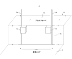
図1において、本実施の形態によるトラックバースには、2つの当たり止めゴム(以下、「突起部」という。)11a,11bをその外側両端の距離がトラックの車幅と同程度か若干長くなる位置でプラットフォーム10の側面10bに取り付ける。突起部11a,11bの上面はプラットフォーム上面10aと略面一となっている。
A first embodiment of the present invention will be described below with reference to the drawings.
In FIG. 1, the truck berth according to the present embodiment has two stopper rubbers (hereinafter referred to as "protrusions") 11a and 11b whose distance between their outer ends is about the same or slightly longer than the width of the truck. It is attached to the
この1対の突起部11a,11bの外側両端とプラットフォーム側面10bとで形成される角辺に沿って、夫々支柱12a,12bがプラットフォーム10aから鉛直上方向に延出して取り付けられている。
支柱12a,12bには図2に示す構造のベルト(第1の連結手段)30と、図3に示す構造の鋼製チェーン(第2の連結手段)40,40aが掛止可能になっている。ちなみに鋼製チェーン40と鋼製チェーン40aは長さが異なるのみで同じ構造を有している。ベルト30は、支柱12(12a,12b)に掛止するための金具(第1掛止部)32と、トラック荷台の両サイドに夫々設けられたレール(トラックレール)に掛止するための金具(第2掛止部)33を夫々の端に備えている。鋼製チェーン40,40aは、支柱12(12a,12b)に掛止するための金具(第1掛止部)32を両端に備えている。
A belt (first connecting means) 30 having the structure shown in FIG. 2 and steel chains (second connecting means) 40, 40a having the structure shown in FIG. 3 can be hung on the
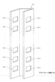
支柱12(12a,12b)には、図10に示すように夫々第1掛止部32を引っ掛けるための穴(第1被掛止部)12-1(12-1a,12-1b)が複数設けられている。 The pillars 12 (12a, 12b) have a plurality of holes (first hooked parts) 12-1 (12-1a, 12-1b) for hooking the first hooking parts 32, respectively. It is provided.
また、トラックレール22には、図4に示すように夫々第2掛止部33を引っ掛けるための穴(第2被掛止部)22-1が複数設けられている。なお図4では、ベルト30や鋼製チェーン40,40aの図示を省略している。 Further, the track rail 22 is provided with a plurality of holes (second hooked portions) 22-1 for hooking the second hook portions 33, respectively, as shown in FIG. Note that in FIG. 4, illustration of the belt 30 and steel chains 40, 40a is omitted.
<突起部の構成>
図12に示すように、突起部11a,11bは、夫々プラットフォーム側面10bにアンカーボルト等で取り付けられる金属ベース(11-1a,11-1b)と、当該金属ベースに取り付けらる当たり止めゴム(11-2a,11-2b)から構成される。金属ベースはプラットフォーム上面10aと略面一になるように取り付けられ、あたり止めゴムは、それよりもトラックテールゲートリフターの厚さ分だけ低い位置に取り付けられる。テールゲートリフターは突起部11a,11bの当たり止めゴム上に着座する。テールゲートリフターが当たり止めゴムに着座したときに、テールゲートリフターの上面は、プラットフォーム上面10aと略面一になる。
<Configuration of protrusion>
As shown in FIG. 12, the
<支柱の取り付け方法>
支柱12a,12bは、突起部11a,11bの外側両端に沿って、プラットフォーム側面10bにアンカーボルト等で取り付けられる。なお、支柱の取り付け方は、これに限らず例えば、突起部11a,11bの金属ベース側面に取り付けるようにしてもよい。支柱12(12a,12b)は、図10に示すように、断面コの字型で少なくとも対向する両側面には、複数の掛止穴12-1(12-1a,12-1b)を備える。支柱12(12a,12b)の中央面にはプラットフォーム側面10bに取り付けるための穴(図示せず)が設けられており、この穴を通してプラットフォーム側面10bあるいは突起部11a,11bの側面にボルトナット等の締結手段によって取り付けられる。支柱12(12a,12b)としてスチール製中量棚(耐荷重300kg)を用いることができる。なお、支柱12の対向する両側面の掛止穴は同じ位置(高さ)に設けられている。支柱12は、プラットフォーム上面10aから鉛直方向に突出しているが、その突出部分のプラットフォーム上面からの高さは1200mm程度あるいはそれ以上であるのが好ましい。また、プラットフォーム上面10aから少なくとも1100mm±50mm程度の位置、および550mm±50mm程度の位置に掛止穴12-1が設けられているのが安全な作業を実現する上で好ましい。
<How to install the prop>
The
<ベルト30の構成>
図2に示すように、ベルト30は、ベルト本体31と、第1掛止部32と、第2掛止部33を備える。第2掛止部33は、リング34を介して、ベルト本体31に取り付けられている。ベルト本体31は玉掛作業用のスリングベルト(繊維スリングを含む。)など、耐荷重性能の高いベルトを用いることができる。
<Configuration of belt 30>
As shown in FIG. 2, the belt 30 includes a belt main body 31, a first hook portion 32, and a second hook portion 33. The second hook portion 33 is attached to the belt body 31 via a ring 34. As the belt main body 31, a belt with high load-bearing performance, such as a sling belt (including a fiber sling) for sling work, can be used.
ベルト30を支柱12a,12bに取り付ける部分には、支柱12a,12bの掛止穴、およびリング34に掛止可能な部品を第1掛止部32として用いる。一方、ベルト30をトラックレール22に取り付ける部分には、トラックレールへの掛止用の専用部品を第2掛止部33として用いる。このように特にトラックレール側の掛止部を取り替え可能にすることにより、着車するトラックのトラックレールのタイプに合わせた適切な掛止部33をベルト本体31に取り付けて使用することができる。
At the portion where the belt 30 is attached to the
<鋼製チェーン40,40aの構成>
図3に示すように、構成チェーン40,40aは、チェーン本体41と両端に第1掛止部32を備えて構成される。鋼製チェーン40は、非着車エリアにおいて隣合う支柱12間を繋ぐために用いられ、鋼製チェーン40aは、着車エリアにおいて一方の支柱12に繋がれたベルト30の解放端と、他方の支柱12とを繋ぐために用いられる。
<Configuration of steel chains 40, 40a>
As shown in FIG. 3, the constituent chains 40, 40a include a chain body 41 and first hooks 32 at both ends. The steel chain 40 is used to connect
図5は、着車エリアを挟む支柱12a,12bへのベルト30,鋼製チェーン40,40aの取り付け状態を示す図である。この図に示すように、支柱12a,12bの着車エリア側には複数のベルト30が繋がれる。さらに一方の支柱(図5では支柱12a)には、ベルト30の掛止位置と同じ位置あるいは近傍の位置に鋼製チェーン40aが繋がれる。支柱12a,12bの非着車エリア側には、鋼製チェーン40が隣接する支柱との間で繋がれる。
FIG. 5 is a diagram showing how the belt 30 and steel chains 40, 40a are attached to the
<作業方法の説明>
非着車エリアの隣合う支柱間は常時鋼製チェーン40で接続しておく。着車エリアについては、荷物の積み降ろし作業のないときは、図6に示すように、鋼製チェーン40aの第1掛止部32を他方の支柱に繋がるベルト30のリング34に掛けることにより、ベルト30と鋼製チェーン40aを一体として支柱12a,12b間に張る。これにより、非作業時におけるプラットフォームからの不慮の転落事故を防止することができる。
<Explanation of work method>
Adjacent columns in the non-arrival area are always connected with a steel chain 40. Regarding the arrival area, when there is no cargo loading/unloading work, as shown in FIG. A belt 30 and a steel chain 40a are integrally stretched between the
次にトラック着車時の作業手順について説明する。
(1)作業開始前は図6の接続状態にあるので、まず着車エリアの支柱12a,12b間の鋼製チェーン40aとこれに繋がるベルト30とを切り離して図5の状態にする。
(2)トラックは荷台の開閉扉をプラットフォーム側に向けて着車し、テールゲートリフターを突起部11a,11b上に着座させる。
(3)その後、ベルト30の他端(第2掛止部33)をトラック荷室内のトラックレール22の掛止穴に取り付ける。
上記(1)~(3)の手順のうち、(1)と(2)の順番を変えてもよい。
Next, we will explain the work procedure when the truck arrives.
(1) Before starting the work, the connection state is as shown in FIG. 6, so first, the steel chain 40a between the
(2) The truck arrives with the loading door facing the platform, and the tailgate lifter is seated on the
(3) After that, the other end of the belt 30 (second hooking portion 33) is attached to the hooking hole of the truck rail 22 in the truck compartment.
Among the steps (1) to (3) above, the order of (1) and (2) may be changed.
以上の手順により、荷物の積み降ろし作業時は、図7に示すように、トラックの荷台を開いた状態で、荷台、テールゲート、プラットフォームの全域にかけてベルト30、および鋼製チェーン40を間断無く張り、作業中の転落事故を防止することができる。 With the above procedure, when loading and unloading cargo, the belt 30 and steel chain 40 are stretched continuously over the entire area of the truck bed, tailgate, and platform with the truck bed open, as shown in Figure 7. , it is possible to prevent falling accidents during work.
荷物の積み降ろし作業後は、全てのベルト30をトラックレールから切り離し、支柱12aの鋼製チェーン40aと支柱12bのベルト30とを連結することによって、再び図6の状態に戻す。
After loading and unloading the cargo, all the belts 30 are separated from the track rails, and the steel chain 40a of the
以上、一つの着車エリアについて説明したが、図1に示した突起部11a,11bと支柱12a、12bとを一組として、同一プラットフォームの側面10bに複数組の突起部11a,11bと支柱12a、12bを設けることができる。これにより、プラットフォーム上で複数の積み降ろし作業が可能となり、複数の作業を同時に行っても安全性を担保することができる。
Although one landing area has been described above, if the
次に図7に基づいて、ベルト30や鋼製チェーン40,40aの支柱への取付高さ等について説明する。
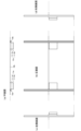
図7は、トラックレール22がトラック荷台の左右両側面に夫々上下2段に設けられている例である。この場合、左右夫々上段のトラックレール22からのベルト30は、支柱12のうち、プラットフォームからの高さ1100mm程度の位置にある掛止穴に取り付け、下段のトラックレール22からのベルト30は、支柱12のうち、プラットフォームからの高さ550mm程度の位置にある掛止穴に取り付ける。この位置に取り付けることにより、作業性を阻害することなくプラットフォームからの転落を効果的に防止することができる。このとき、支柱間を繋ぐ鋼製チェーン40は、支柱12においてベルト30が取り付けられた掛止穴と対向する掛止穴に取り付けるのが好ましい。
Next, based on FIG. 7, the mounting height of the belt 30 and steel chains 40, 40a to the pillars will be explained.
FIG. 7 shows an example in which track rails 22 are provided in two stages, upper and lower, on both left and right sides of a truck bed. In this case, the belts 30 from the upper track rails 22 on the left and right sides are attached to the retaining holes located at a height of about 1100 mm from the platform in the
トラックレール22がトラック荷台の左右両側面に夫々一段のみ設けられている場合は、それぞれのトラックレール22から、プラットフォームからの高さ1100mm程度の位置にある掛止穴12-1に取り付けるのが好ましい。支柱12に掛止穴(より具体的には2つの上下隣接する穴で形成される被掛止部)を、例えば100mm程度の間隔で設けておけば、トラックレール22が片側3段以上の場合も含めて、作業状態に合わせて適宜適切な高さにベルト30あるいは鋼製チェーン40を取り付けることができる。
If the track rails 22 are provided in only one stage on each of the left and right sides of the truck bed, it is preferable to attach them to the latching holes 12-1 located at a height of about 1100 mm from the platform from each track rail 22. . If the
ベルト30の長さは、トラックのテールゲートの奥行き+トラックレールの荷台開口部付近の掛止穴までの長さに、着車の際の誤差等を考慮して若干のマージンを加えた値にするのが好ましい。鋼製チェーン40aの長さは、支柱12a,12bの間隔とベルト30の長さから決定することができる。鋼製チェーン40の長さは、非着車エリアの支柱間隔に基づいて決定することができる。
The length of the belt 30 is the depth of the truck's tailgate + the length to the latch hole near the loading platform opening of the truck rail, plus a slight margin to account for errors when landing, etc. It is preferable to do so. The length of the steel chain 40a can be determined from the distance between the
(他の実施例1)
図8に示すように、プラットフォーム10の突起部11a,11b間にドックレベラー13を設けるようにしてもよい。これにより、図9に示すように、トラックのテールゲートリフターとプラットフォーム間の隙間を効果的に塞ぎ、より安全な積み降ろし作業が可能になる。
(Other Example 1)
As shown in FIG. 8, a
(他の実施例2)
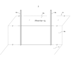
上記の説明において、着車エリアにおいて一対の突起部11(11a,11b)を、プラットフォーム側面に取り付けることとしたが、図11に示すように、この突起部11(11a,11b)を設けなくても従来に比べて優れた転落防止効果を奏する。この場合は、支柱12(12a,12b)をトラック着車時の荷台の両側面位置に対応するプラットフォーム側面の位置に当該荷台の幅と略同一の間隔をもって鉛直方向に取り付ける。その他の取り付け方は図1を用いて説明したとおりである。
(Other Example 2)
In the above explanation, a pair of protrusions 11 (11a, 11b) were attached to the side surface of the platform in the landing area, but as shown in FIG. It also has a superior fall prevention effect compared to conventional methods. In this case, the struts 12 (12a, 12b) are vertically attached at positions on the side surfaces of the platform corresponding to the positions on both sides of the loading platform when the truck arrives, with an interval approximately equal to the width of the loading platform. Other attachment methods are as described using FIG. 1.
なお、突起部11を設ける場合は、一対の突起部11a,11bを一体として、一つの四角柱形状で構成することもできる。この場合は、図8に示すような、突起部11a,11b間にドックレベラー13を設けることはできないが、テールゲートリフターを安定して着座させることができるという効果を奏する。
In addition, when the protrusion part 11 is provided, the pair of
(他の実施例3)
プラットフォーム10には、その側面の上部全体に亘って断面が蒲鉾(半円)状の当たり止めゴム113を装着するようにしても良い。本実施例では、この場合の支柱12(12a,12b)の取り付け方について説明する。
(Other Example 3)
A stopper rubber 113 having a semicircular cross section may be attached to the
この場合、図13に示すように、トラック着車位置の荷台両外側に当たる位置の当たり止めゴム11の一部を、鉛直方向に支柱12の幅で切断する。切断箇所を符号19で示す。すなわち、プラットフォーム側面10bに支柱12を立設する際に支柱12が当たる部分のみを切断して、プラットフォーム側面10bを露出させる。
In this case, as shown in FIG. 13, a portion of the stopper rubber 11 at a position corresponding to both outer sides of the loading platform at the truck arrival position is cut vertically to the width of the
図14に示すように、断面コの字型の支柱12の中央面を露出したプラットフォームの側面10bの略全体に亘って鉛直方向に当接させる。そして、支柱12の中央面の少なくともプラットフォーム側面10bの上部、下部の2箇所を図15に示すアンカーボルト71で固定する。
As shown in FIG. 14, the center surface of the
このようにして設置された支柱12には、図16に示すように、上述した適切な高さ位置にベルト(連結手段)30や鋼製チェーン(第2の連結手段)40が掛けられる。この使用方法は上述したとおりである。
As shown in FIG. 16, a belt (coupling means) 30 and a steel chain (second coupling means) 40 are hung on the
<本実施形態の効果>
以上、本実施の形態によれば、荷物の積み降ろし作業の際の人や物の転落を防止して、安全な作業を低コストで実現することができる。
特に、本実施の形態の構成は、主な工事はプラットフォーム側面と両突起部の外側角に金属製の支柱を取り付けるのみなので、現状支柱の無いトラックバースでも簡単な工事で支柱を取り付けることができ、また容易に取り外すことができる。さらに退去の際等の原状復帰工事も容易に行うことができる。
<Effects of this embodiment>
As described above, according to the present embodiment, it is possible to prevent people and objects from falling during loading and unloading work, and to realize safe work at low cost.
In particular, with the configuration of this embodiment, the main work is only to attach metal supports to the side surfaces of the platform and the outer corners of both protrusions, so supports can be installed with simple work even on truck berths that currently do not have supports. , and can also be easily removed. Furthermore, work to restore the building to its original state when moving out can be easily carried out.
本実施の形態は、輸送時の荷崩れ防止のために、荷物を固定して運ぶときに使用するトラックレールを荷物の積み降ろしの際にも有効に利用するものである。このトラックレールは、多数の掛止穴を有し荷台内両側に夫々水平方向に延在する。そして、荷物の積み降ろし作業の際は、プラットフォームの支柱側に先にベルトの一端を掛けた後に、トラックレールの掛止穴にベルトの他端を掛けるので、トラックの大きさやテールゲートリフターの長さ、あるいは停車位置に拘らず、強度の高いベルトを常に適度な緊張状態で張ることができる。このため、ベルトの取り付け後は、プラットフォームとトラック荷台の間にあるテールゲートリフターを挟んでベルトが安全性の高い手すりの役割を担い、作業者や荷物の転落を効果的に防止することができる。 In this embodiment, in order to prevent the cargo from collapsing during transportation, the track rails used to securely transport the cargo are also effectively used when loading and unloading the cargo. This track rail has a large number of latching holes and extends horizontally on both sides of the loading platform. When loading and unloading cargo, one end of the belt is first hung on the support side of the platform, and then the other end of the belt is hung on the hooking hole of the track rail. The high-strength belt can always be tensioned at an appropriate level, regardless of the vehicle's speed or the vehicle's stopping position. Therefore, after the belt is installed, the belt acts as a highly safe handrail by sandwiching the tailgate lifter between the platform and the truck bed, effectively preventing workers and cargo from falling. .
本実施の形態では、断面コの字型の支柱12a,12bの中央面をプラットフォーム側面10bに当接して取り付けて、当該支柱の対向面のうち一方の面の掛止穴をベルト30(連結手段)の取り付け用に用い、他方の面の掛止穴を鋼製チェーン40(第2の連結手段)の取り付け用に用いる。これにより、ベルト30と鋼製チェーン40、あるいは鋼製チェーン40同士が互いに干渉せず、夫々適切な高さに取り付けることができる。
In this embodiment, the center surfaces of the
また、本実施の形態では、非作業時は、着車エリアの支柱間を一本の鋼製チェーンで繋ぐのではなく、ベルト30と鋼製チェーン40aとを連結させて繋ぐ構成としている。荷物の積み降ろし作業時は、鋼製チェーン40aは不使用状態となるが、一本の鋼製チェーン40で繋いだ場合に比べて長さが短いので、作業の邪魔にならず、より安全な作業が可能となる。 Furthermore, in this embodiment, when the vehicle is not in operation, the supports in the landing area are not connected by a single steel chain, but are connected by a belt 30 and a steel chain 40a. When loading and unloading cargo, the steel chain 40a is not used, but its length is shorter than when connected with a single steel chain 40, so it does not interfere with the work and is safer. Work becomes possible.
次に本発明の第2の実施の形態について説明する。
第1の実施の形態では、所謂垂直タイプのプラットフォームについて一対の支柱12(12a,12b)を設ける場合について説明したが、本実施の形態では特許文献1に記載されているような、トラック着車時にテールゲートリフターをプラットフォーム下部の空洞内に収納するタイプ(所謂突き出しタイプ)のプラットフォームに支柱を設ける場合について説明する。
Next, a second embodiment of the present invention will be described.
In the first embodiment, a case where a pair of support columns 12 (12a, 12b) are provided for a so-called vertical type platform has been described, but in this embodiment, a truck landing platform as described in
垂直タイプのプラットフォームに対して支柱を取り付ける場合、図17(a)に示すように、プラットフォームの側面に支柱を2箇所以上で止めることができるが、突き出しタイプでは、図17(b)に示すように支柱の固定箇所が限られているため、支柱が不安定になりやすい。ここで、符号10cは、プラットフォーム10の突き出し部を示す。
When attaching a support to a vertical type platform, the support can be fixed at two or more places on the side of the platform as shown in Figure 17(a), but with a protruding type, the support can be fixed at two or more places as shown in Figure 17(b). Because there are only a limited number of places where the pillars can be fixed, the pillars tend to become unstable. Here, the reference numeral 10c indicates a protruding portion of the
以下、この問題に対処して、支柱を簡便に安定的に設置する方法について図18を参照しながら説明する。なお、本実施の形態では、断面コの字型の支柱12に代えて、断面円型の単管パイプの支柱60を用いる。ここで支柱60は、第1の実施の形態と同様に着車エリアの左右両側に夫々設けられるため、必要により、夫々の側を示す添え字a,bを付して符号60a、60bというように表す。他の要素についても同様である。図20に本実施の形態で用いる部品の一覧を示す。
Hereinafter, a method for easily and stably installing a support column to deal with this problem will be described with reference to FIG. 18. In this embodiment, instead of the
支柱60を立設するために、突き出しタイプのプラットフォームに対して、まず縦固定用の単管パイプ50をプラットフォーム空洞部内に固定する。 In order to erect the support column 60, a single pipe 50 for vertical fixation is first fixed in the platform cavity of the protruding type platform.
固定の仕方は、単管パイプ50の上側をプラットフォーム突き出し部10cの天井部に固定ベース52で固定する一方、単管パイプ50の下側は、着車部底面(以下、単に「底面」という)2との間にミニジャッキ53を固定して適度な強度で単管パイプ50をプラットフォーム突き出し部10cの天上と底面2との間に固定する。
The method of fixing is that the upper side of the single pipe 50 is fixed to the ceiling of the platform protruding part 10c with the fixing base 52, while the lower side of the single pipe 50 is fixed to the bottom surface of the landing section (hereinafter simply referred to as "bottom surface"). A mini jack 53 is fixed between the two and the single pipe 50 is fixed with appropriate strength between the top and the
また底面2にパイプスタンド56を固定し、当該パイプスタンド2上に単管パイプ型の支柱60を立設する。そして、この支柱60と、縦固定用の単管パイプ50との間を水平方向に横固定用の単管パイプ51を設置する。この設置のしかたは、図18に示すように、支柱60側には、T型パイプジョイント(例えば、DCクロームチーズ回転止ネジネジ付)55、縦固定用の単管パイプ50側側にはクランプ54を用いて固定することができる。空洞内の2箇所以上でこの横固定用の単管パイプ51を用いて固定することによって支柱60を安定して立設することができる。第1の実施の形態と同様に、この支柱60は着車エリアの、トラックの荷台幅に合わせて左右一対を一組として立設される。したがって、上記の設置作業は一対の支柱60(60a.60b)の夫々について実施する。
Further, a pipe stand 56 is fixed to the
図18では、緩衝用にプラットフォームの突き出し部10cに沿って水平に蒲鉾状の当たり止めゴム(突起部)11を取り付けた状態で支柱60を設置している。勿論、当たり止めゴム11を設けずに支柱60を設置したり、当たり止めゴム11に支柱60の幅で切り込みを入れて、プラットフォーム突き出し部10cに近接させて支柱60を設置したりするなど適宜変更して実施してもよい。 In FIG. 18, the support 60 is installed with a semi-cylindrical stopper rubber (protrusion) 11 horizontally attached along the protrusion 10c of the platform for cushioning purposes. Of course, modifications may be made as appropriate, such as installing the support 60 without providing the stop rubber 11, or making a cut in the stop rubber 11 with the width of the support 60, and installing the support 60 close to the platform protrusion 10c. It may also be carried out.
このようにして設置された単管パイプ型の支柱60(60a,60b)には、ベルト(連結手段)30や鋼製チェーン(第2の連結手段)40を張るため、図19に示すように、第1の実施の形態で述べた適切な高さ位置に単管金具62(62a,62b)が装着される。また支柱60(60a,60b)の上部には端末キャップ61(61a,61b)が装着される。 In order to stretch the belt (connection means) 30 and steel chain (second connection means) 40 to the monotube pipe-type supports 60 (60a, 60b) installed in this way, as shown in FIG. The single pipe fittings 62 (62a, 62b) are installed at the appropriate height positions described in the first embodiment. Furthermore, a terminal cap 61 (61a, 61b) is attached to the upper part of the support column 60 (60a, 60b).
各単管金具62は、2箇所にベルト30や鋼製チェーン40の掛止部32を掛止するための金具(被掛止部)62-1を備えている。この単管金具62の被掛止部62-1に、着車エリアにはベルト30を掛け、着車エリア以外には、鋼製チェーン40を掛ける。 Each single tube fitting 62 is provided with metal fittings (latched portions) 62-1 at two locations for hooking the hooking portion 32 of the belt 30 or the steel chain 40. A belt 30 is hung on the hooked part 62-1 of the single pipe fitting 62 in the landing area, and a steel chain 40 is hung in the area other than the landing area.
単管金具62の被掛止部62-1は、両方、あるいは一方がネジ式になっており、ネジを締めることにより単管金具62の内側にネジの先が突出して支柱60を締め付けて固定されるようになっている。 Both or one of the hooked parts 62-1 of the single pipe fitting 62 is threaded, and when the screws are tightened, the tip of the screw protrudes inside the single pipe fitting 62, and the support column 60 is tightened and fixed. It is now possible to do so.
このように構成されたトラックバースにおける荷物の積み降ろし作業は、第1の実施の形態と同様である。作業時のベルトや鋼製チェーンの掛止状態を図21に示す。 Loading and unloading operations on the truck berth configured in this manner are similar to those in the first embodiment. Figure 21 shows how the belt and steel chain are latched during work.
<本実施形態の効果>
以上、本実施の形態によれば、突き出しタイプのプラットフォームに対しても、簡便に支柱の立設、およびベルトを張ることができ、作業エリアでは、トラックと支柱間でベルとを張り、非作業エリアではチェーンを張ることにより、荷物の積み降ろし作業時の転落を防止して安全な作業が可能になる。
<Effects of this embodiment>
As described above, according to this embodiment, supports can be easily erected and belts can be tensioned even on a protruding type platform. Chains are placed in the area to prevent falls during loading and unloading operations, allowing for safe work.
本発明は上述した実施の形態に限定されず、その要旨を逸脱しない範囲で種々変形して実現することができる。例えば、トラック荷台内の荷物を固定させるための、両端に第2掛止部33を備える収納ベルトの一端に第1掛止部32を共に取り付けて、プラットフォームへの着車時にこの収納ベルトの第1掛止部を支柱12,60に掛け、他端の掛止部33をトラックレールに掛けるようにしてもよい。
The present invention is not limited to the embodiments described above, and can be implemented with various modifications without departing from the gist thereof. For example, the first hooking portion 32 may be attached to one end of a storage belt having second hooking portions 33 at both ends for securing cargo in the truck bed, and the One hooking portion may be hung on the
また各実施の形態、実施例で述べた構成は単独であるいは組み合わせて実現することができる。 Furthermore, the configurations described in each embodiment and example can be implemented alone or in combination.
1 トラックバース
11(11a,11b) 突起部
12(12a,12b),60(60a,60b) 支柱
13 ドックレベラー
20 トラック(車両)
21 テールゲートリフター
22 トラックレール
30 ベルト(連結手段、第1の連結手段)
31 ベルト本体
32 第1掛止部
33 第2掛止部
40,40a 鋼製チェーン(第2の連結手段)
50 単管パイプ
51 単管パイプ
52 固定ベース
53 ミニジャッキ
54 クランプ
56 パイプスタンド
61 端末キャップ
62 単管金具(被掛止部)
71 アンカーボルト
1 Truck berth 11 (11a, 11b) Protrusion 12 (12a, 12b), 60 (60a, 60b)
21 Tailgate lifter 22 Track rail 30 Belt (connection means, first connection means)
31 Belt body 32 First hooking part 33 Second hooking part 40, 40a Steel chain (second connection means)
50 Single pipe 51 Single pipe 52 Fixed base 53 Mini jack 54 Clamp 56 Pipe stand 61 Terminal cap 62 Single pipe fitting (latched part)
71 Anchor bolt
Claims (6)
着車部床面側から前記プラットフォームの側面に沿って鉛直方向に取り付けられた一対の支柱を備え、
当該一対の支柱の夫々は、前記トラックの荷台内部の両側面上に水平方向に延設されたトラックレールの被掛止部と夫々連結手段によって連結させるための被掛止部を有し、前記トラックの着車位置に該トラックの荷台の幅と略同一の間隔で前記プラットフォームの上面の高さよりも上方に延出していることを特徴とするトラックバース。 A truck berth having a platform for loading and unloading cargo from a truck bed,
A pair of columns are installed vertically along the side surface of the platform from the floor side of the landing section,
Each of the pair of struts has a hooked portion that is connected to a hooked portion of a track rail extending horizontally on both sides of the inside of the truck bed by a connecting means, and A truck berth, characterized in that the truck berth extends above the height of the top surface of the platform at an interval substantially equal to the width of the truck bed at the landing position of the truck.
前記一対の支柱は、夫々前記突起部の外側両側面と前記プラットフォームの側面とで形成される角部に取り付けられていることを特徴とする請求項1に記載のトラックバース。 The side surface of the platform is provided with protrusions for seating the left and right ends of the tailgate lifter of the truck, respectively, so that the upper surface is substantially flush with the upper surface of the platform;
The truck berth according to claim 1, wherein the pair of support columns are each attached to a corner formed by both outer side surfaces of the protrusion and a side surface of the platform.
前記突き出し部の天井面と、前記着車部床面との間で鉛直方向に固定される第一の支持手段と、
前記第一の指示手段と、前記支柱との間で水平方向に固定される一又は二以上の第二の指示手段と、
を備えたことを特徴とする請求項1に記載のトラックバース。 The platform has a protrusion that can accommodate a tailgate lifter of the truck,
a first support means fixed in the vertical direction between the ceiling surface of the protruding part and the floor surface of the landing part;
one or more second indicating means fixed in the horizontal direction between the first indicating means and the support;
The truck berth according to claim 1, further comprising:
前記支柱は、略同一の高さ位置に2つの被掛止部を有し、一方の被掛止部は、前記連結手段を掛止させるためのものであり、他方の被掛止部は、隣接する他の組の支柱の被掛止部との間で第2の連結手段を掛止させるためのものであることを特徴とする請求項1に記載のトラックバース。 The platform includes a plurality of sets of supports, with the pair of supports as one set,
The support column has two latched parts at approximately the same height position, one latched part is for latching the connecting means, and the other latched part is 2. The truck berth according to claim 1, wherein the second connecting means is adapted to be latched to a latched portion of another set of adjacent struts.
前記複数の連結手段の前記第1掛止部を前記一対の支柱の被掛止部に夫々掛止させる支柱側連結手段取付段階と、
駐車されたトラックのテールゲートリフターを前記プラットフォームの上面と略同一の高さにセットする段階と、
その後、前記複数の連結手段の前記第2掛止部を、前記トラックの荷台内部両側面の前記トラックレールの被掛止部に夫々掛止させるトラック側連結手段取付段階と、
を含むことを特徴とする作業方法。 In the truck berth according to claim 1, a method of work before loading and unloading cargo on a truck using a plurality of the connecting means each having a first hooking portion and a second hooking portion at both ends, the method comprising:
a step of attaching the first hooking portions of the plurality of connecting means to the hooked portions of the pair of columns;
setting a tailgate lifter of a parked truck at approximately the same height as the top of the platform;
Thereafter, a step of attaching the second hooking portions of the plurality of coupling means to the hooked portions of the track rail on both sides of the inside of the truck bed;
A working method characterized by including.
前記複数の連結手段の前記第1掛止部を前記一対の支柱の被掛止部に夫々掛止させる支柱側連結手段取付段階と、
トラックの荷台をプラットフォームに近接させて着車させる段階と、
その後、前記複数の連結手段の前記第2掛止部を、前記トラックの荷台内部両側面の前記トラックレールの被掛止部に夫々掛止させるトラック側連結手段取付段階と、
作業を行わないエリアの互いに隣接する前記支柱間を第2の連結手段で繋ぐ段階と、
を含むことを特徴とする作業方法。 In the truck berth according to claim 4, a method of working before loading and unloading cargo on a truck using a plurality of the connecting means each having a first hooking portion and a second hooking portion at both ends,
a step of attaching the first hooking portions of the plurality of connecting means to the hooked portions of the pair of columns;
landing the truck with the bed of the truck in close proximity to the platform;
Thereafter, a step of attaching the second hooking portions of the plurality of coupling means to the hooked portions of the track rail on both sides of the inside of the truck bed;
connecting the adjacent pillars in an area where no work is to be performed using a second connecting means;
A working method characterized by including.
Priority Applications (1)
| Application Number | Priority Date | Filing Date | Title |
|---|---|---|---|
| JP2022077274A JP2023166301A (en) | 2022-05-09 | 2022-05-09 | Truck berth and working method |
Applications Claiming Priority (1)
| Application Number | Priority Date | Filing Date | Title |
|---|---|---|---|
| JP2022077274A JP2023166301A (en) | 2022-05-09 | 2022-05-09 | Truck berth and working method |
Publications (1)
| Publication Number | Publication Date |
|---|---|
| JP2023166301A true JP2023166301A (en) | 2023-11-21 |
Family
ID=88836713
Family Applications (1)
| Application Number | Title | Priority Date | Filing Date |
|---|---|---|---|
| JP2022077274A Pending JP2023166301A (en) | 2022-05-09 | 2022-05-09 | Truck berth and working method |
Country Status (1)
| Country | Link |
|---|---|
| JP (1) | JP2023166301A (en) |
Citations (3)
| Publication number | Priority date | Publication date | Assignee | Title |
|---|---|---|---|---|
| JPH0416741U (en) * | 1990-05-31 | 1992-02-12 | ||
| JPH0544934U (en) * | 1991-11-19 | 1993-06-15 | 川鉄運輸株式会社 | Safety device for cargo handling work |
| JP2020138833A (en) * | 2019-02-27 | 2020-09-03 | 株式会社竹中工務店 | Truck berth structure |
-
2022
- 2022-05-09 JP JP2022077274A patent/JP2023166301A/en active Pending
Patent Citations (3)
| Publication number | Priority date | Publication date | Assignee | Title |
|---|---|---|---|---|
| JPH0416741U (en) * | 1990-05-31 | 1992-02-12 | ||
| JPH0544934U (en) * | 1991-11-19 | 1993-06-15 | 川鉄運輸株式会社 | Safety device for cargo handling work |
| JP2020138833A (en) * | 2019-02-27 | 2020-09-03 | 株式会社竹中工務店 | Truck berth structure |
Similar Documents
| Publication | Publication Date | Title |
|---|---|---|
| JP6227153B2 (en) | Ceiling unit and elevator car with ceiling unit | |
| US20150060202A1 (en) | Handrail assembly for a trailer | |
| US7000733B2 (en) | Work platform | |
| JP2023166301A (en) | Truck berth and working method | |
| CN104602995A (en) | Overhead conveyor with self-supporting load-carrying frame | |
| JP6048996B1 (en) | Superstructure of a ship for transportation of vehicles and the like, and a ship for transportation of vehicles equipped with the same | |
| US10730661B2 (en) | Cargo pallet with extruded slot | |
| MXPA03000249A (en) | Tri-level railcar. | |
| JPH08324453A (en) | Vehicle heavy loading structure | |
| JP2017214732A (en) | Tool for preventing falling of stepladder | |
| JP4653479B2 (en) | Loading platform steps | |
| JP5756479B2 (en) | Ladder equipment for railway vehicles | |
| KR20150115137A (en) | Lashing bridge for container ship | |
| JP6679046B2 (en) | Cargo structure and vehicle | |
| KR200447642Y1 (en) | Base rail for container | |
| JP5009969B2 (en) | STANCE HOLDING STRUCTURE, STANCE HOLDING HOUSING, AND VEHICLE HAVING THE HOUSING | |
| RU2016141080A (en) | VEHICLE, AT LEAST, WITH TWO FOUND ON THE VEHICLE CONTAINERS, AND ALSO WAY TO LOAD CONTAINERS | |
| US3195944A (en) | Vehicle wall bracing means | |
| JP7582105B2 (en) | Goods handling equipment | |
| JP7764245B2 (en) | Retractable fastening device for portable work equipment | |
| RU217164U1 (en) | Body of a covered freight wagon | |
| KR200477405Y1 (en) | Lashing bridge | |
| JP2008201208A (en) | Lashing rail for floor of truck loading space | |
| JP6751315B2 (en) | Transportation platform with scaffolding | |
| JP4724153B2 (en) | Storage space remodeling method for elevator type multi-story parking system |
Legal Events
| Date | Code | Title | Description |
|---|---|---|---|
| A621 | Written request for application examination |
Free format text: JAPANESE INTERMEDIATE CODE: A621 Effective date: 20250122 |
|
| A977 | Report on retrieval |
Free format text: JAPANESE INTERMEDIATE CODE: A971007 Effective date: 20251016 |
|
| A131 | Notification of reasons for refusal |
Free format text: JAPANESE INTERMEDIATE CODE: A131 Effective date: 20251028 |
|
| A521 | Request for written amendment filed |
Free format text: JAPANESE INTERMEDIATE CODE: A523 Effective date: 20251106 |
|
| A01 | Written decision to grant a patent or to grant a registration (utility model) |
Free format text: JAPANESE INTERMEDIATE CODE: A01 Effective date: 20260203 |