JP2023158366A - production management system - Google Patents
production management system Download PDFInfo
- Publication number
- JP2023158366A JP2023158366A JP2022068162A JP2022068162A JP2023158366A JP 2023158366 A JP2023158366 A JP 2023158366A JP 2022068162 A JP2022068162 A JP 2022068162A JP 2022068162 A JP2022068162 A JP 2022068162A JP 2023158366 A JP2023158366 A JP 2023158366A
- Authority
- JP
- Japan
- Prior art keywords
- information
- program
- manufacturing
- display screen
- analysis information
- Prior art date
- Legal status (The legal status is an assumption and is not a legal conclusion. Google has not performed a legal analysis and makes no representation as to the accuracy of the status listed.)
- Granted
Links
Images


Landscapes
- Management, Administration, Business Operations System, And Electronic Commerce (AREA)
- General Factory Administration (AREA)
Abstract
Description
本発明は、製造工場において製品の製造管理を行う生産管理システムに関する。 The present invention relates to a production management system that manages the manufacturing of products in a manufacturing factory.
原材料を加工して製品を製造する製造工場において、加工装置や検査装置などの製造装置の駆動制御を行うPLC(Programmable Logic Controller)が知られている(例えば、特許文献1参照)。このPLCは、駆動制御に関する情報を付属のディスプレイに表示し、また付属のメモリに蓄積する。駆動制御に関する情報は、製造経時情報やエラー情報などである。製造経時情報は、製造装置に電源が投入されているか否かや、待機状態であるか否かや、稼働状態であるか否かや、稼働開始時からの製造個数などの情報である。エラー情報は、エラーの種別を示すエラーコードなどである。 BACKGROUND ART In manufacturing factories that process raw materials to manufacture products, PLCs (Programmable Logic Controllers) that control the drive of manufacturing equipment such as processing equipment and inspection equipment are known (for example, see Patent Document 1). This PLC displays information regarding drive control on an attached display and also stores it in an attached memory. Information regarding drive control includes manufacturing time information, error information, and the like. The manufacturing time information includes information such as whether the manufacturing device is powered on, whether it is in a standby state, whether it is in an operating state, and the number of products manufactured since the start of operation. The error information includes an error code indicating the type of error.
また、駆動制御に関する情報をデータベースに保存するシステムが知られている(例えば、特許文献2参照)。 Furthermore, a system is known that stores information regarding drive control in a database (for example, see Patent Document 2).
製造工場において一般に、製造効率向上のため、生産管理を行う生産管理システムの構築が望まれている。しかしながらPLCは、複数のPLCが取得した情報を統括して管理する生産管理システムの機能は有していない。 Generally, in manufacturing factories, it is desired to construct a production management system for controlling production in order to improve manufacturing efficiency. However, the PLC does not have the function of a production management system that collectively manages information acquired by multiple PLCs.
本発明は、前述された事情に鑑みてなされたものであり、その目的は、PLCが取得した情報を統括してリアルタイムで表示可能であり、かつ当該情報を統括して解析し、解析情報を生成可能な生産管理システムを提供することである。 The present invention has been made in view of the above-mentioned circumstances, and its purpose is to be able to centrally display information acquired by a PLC in real time, and to centrally analyze the information and generate analysis information. The objective is to provide a production management system that can generate
(1) 本発明に係る生産管理システムは、装置ID、製造経時情報、及びエラー情報を少なくとも含む元情報を定期的に取得する複数のコントローラと、第1プログラム、第2プログラム、及び第3プログラムを実装する管理装置と、元情報データベース及び解析情報データベースを記憶するメモリと、端末装置と、を備える。上記コントローラ、上記管理装置、及び上記端末装置は、通信ネットワークを通じて通信可能である。上記第1プログラムは、上記元情報を上記コントローラから取得して上記元情報データベースに登録させる元情報登録処理を実行する。上記第2プログラムは、上記元情報を定期的に取得してリアルタイム表示画面データを定期的に生成する生成処理と、上記リアルタイム表示画面データを上記端末装置に定期的に送信する第1送信処理と、を実行する。上記第3プログラムは、上記エラー情報が示すエラーの発生日時を上記元情報データベースから取得するエラー情報取得処理と、上記装置ID及び上記発生日時を対応付けた解析情報を生成する解析情報生成処理と、上記解析情報を上記解析情報データベースに登録させる解析情報登録処理と、を実行する。 (1) The production management system according to the present invention includes a plurality of controllers that periodically acquire original information including at least device ID, manufacturing elapsed information, and error information, and a first program, a second program, and a third program. A management device that implements the above, a memory that stores an original information database and an analysis information database, and a terminal device. The controller, the management device, and the terminal device are capable of communicating through a communication network. The first program executes a source information registration process that acquires the source information from the controller and registers the source information in the source information database. The second program includes a generation process that periodically acquires the source information and periodically generates real-time display screen data, and a first transmission process that periodically transmits the real-time display screen data to the terminal device. , execute. The third program includes an error information acquisition process that acquires the date and time of occurrence of the error indicated by the error information from the source information database, and an analysis information generation process that generates analysis information that associates the device ID and the date and time of occurrence. , an analysis information registration process for registering the analysis information in the analysis information database.
各コントローラは、元情報を、数十m秒や数百m秒や数秒などの時間間隔で定期的に取得或いは生成する。第1プログラムは、各コントローラから元情報をそれぞれ取得して元情報データベースに登録する。第2プログラムは、各コントローラから製造経時情報をそれぞれ取得し、取得した各製造経時情報を端末装置に定期的に送信し、端末装置のディスプレイにリアルタイム表示画面を一括で表示する。第3プログラムは、元情報データベースからエラー情報を取得して解析情報を生成する。第3プログラムは、生成した解析情報を解析情報データベースに登録する。すなわち、本発明に係る生産管理システムは、コントローラが取得した情報を統括してリアルタイムで表示可能であり、かつ当該情報を統括して解析し、解析情報を生成することができる。 Each controller periodically acquires or generates original information at time intervals such as tens of milliseconds, hundreds of milliseconds, or several seconds. The first program acquires original information from each controller and registers it in the original information database. The second program acquires manufacturing elapsed information from each controller, periodically transmits the acquired manufacturing elapsed information to the terminal device, and displays a real-time display screen on the display of the terminal device all at once. The third program acquires error information from the original information database and generates analysis information. The third program registers the generated analysis information in the analysis information database. That is, the production management system according to the present invention can centrally display the information acquired by the controller in real time, and can centrally analyze the information and generate analysis information.
(2) 本発明に係る生産管理システムは、上記解析情報データベースから上記解析情報を取得して、上記端末装置に送信するための解析情報表示画面データを生成する第4プログラムをさらに備えていてもよい。 (2) The production management system according to the present invention may further include a fourth program that acquires the analysis information from the analysis information database and generates analysis information display screen data to be transmitted to the terminal device. good.
例えば第2プログラムが解析情報表示画面データを生成する場合、解析情報表示画面データの生成が遅延したり当該生成に不具合が生じたりした場合に、端末装置における製造経時情報のリアルタイム表示にも支障が生じるおそれがある。第4プログラムが解析情報表示画面データを生成するから、製造経時情報のリアルタイム表示に支障を及ぼすことなく、解析情報を端末装置に表示させることができる。 For example, when the second program generates analysis information display screen data, if the generation of the analysis information display screen data is delayed or a problem occurs, the real-time display of manufacturing elapsed information on the terminal device may also be affected. There is a risk that this may occur. Since the fourth program generates the analysis information display screen data, the analysis information can be displayed on the terminal device without interfering with the real-time display of the manufacturing elapsed information.
(3) 上記メモリは、製品IDと上記装置IDと製造予定とを少なくとも対応付けた製造予定データベースをさらに記憶し、上記解析情報生成処理は、上記製造予定データベースから上記装置ID及び製造予定を取得する製造予定取得処理と、上記解析情報及び上記製造予定に基づいて、上記製品IDと、上記装置IDと、上記エラー情報と、エラー発生日時と、上記製造予定とを対応付けた上記解析情報を生成する処理と、を含んでいてもよい。 (3) The memory further stores a manufacturing schedule database in which at least the product ID, the device ID, and the manufacturing schedule are associated with each other, and the analysis information generation process acquires the device ID and the manufacturing schedule from the manufacturing schedule database. and the analysis information that associates the product ID, the device ID, the error information, the date and time of error occurrence, and the manufacturing schedule based on the analysis information and the manufacturing schedule. It may also include a process of generating.
解析情報は、製造予定と、元情報のエラー情報とに基づいて生成される。したがって、より詳細な解析情報の生成が可能となる。 The analysis information is generated based on the manufacturing schedule and error information of the original information. Therefore, more detailed analysis information can be generated.
(4) 上記メモリは、1日ごとの上記製造経時情報の集計である集計情報が登録される集計データベースをさらに記憶していてもよい。上記第2プログラムは、上記集計情報に基づいて集計表示画面データを生成する集計表示画面データ生成処理と、上記集計表示画面データを上記端末装置に送信する第2送信処理と、をさらに実行する。 (4) The memory may further store a tally database in which tally information that is a tally of the manufacturing time information for each day is registered. The second program further executes a total display screen data generation process that generates total display screen data based on the total information, and a second transmission process that transmits the total display screen data to the terminal device.
第2プログラムにより、1日ごとに集計した集計表示画面を端末装置に表示することができる。 The second program allows a daily total to be displayed on the terminal device.
(5) 上記リアルタイム表示画面データが示すリアルタイム表示画面は、複数の装置アイコンを含み、上記第2プログラムは、上記装置アイコンが選択されたことに基づいて、選択された当該装置アイコンと対応付けられた上記装置ID、及び上記解析情報表示画面データの生成を指示する情報を上記第4プログラムに受け渡す指示処理をさらに実行してもよい。 (5) The real-time display screen indicated by the real-time display screen data includes a plurality of device icons, and the second program is associated with the selected device icon based on the selection of the device icon. An instruction process may be further executed in which the device ID and information instructing generation of the analysis information display screen data are passed to the fourth program.
リアルタイム表示画面において、管理担当者等によって装置アイコンが選択されると、選択された装置アイコンが示す装置について、エラーの発生日時を示す解析情報表示画面が表示される。すなわち、管理担当者等は、エラーの発生日時などの詳細を装置ごとに確認することができる。 When a device icon is selected by a person in charge of management or the like on the real-time display screen, an analysis information display screen showing the date and time of occurrence of an error is displayed for the device indicated by the selected device icon. That is, a person in charge of management or the like can check details such as the date and time of error occurrence for each device.
(6) 上記元情報データベースをRAMに展開して当該元情報データベースへのアクセスを行うサーバであって、1つの上記製造経時情報に1つのキーを設定して当該元情報データベースに登録するサーバをさらに備えていてもよい。 (6) A server that expands the source information database to RAM and accesses the source information database, and that sets one key for one piece of the manufacturing time information and registers it in the source information database. You may also have more.
上記構成のサーバは、いわゆるRedis(登録商標)サーバである。Redisサーバを用いることにより、元情報データベースへの元情報の登録及び元情報データベースからの解析用情報の読み出しを高速で行うことができる。 The server with the above configuration is a so-called Redis (registered trademark) server. By using the Redis server, it is possible to register source information in the source information database and read analysis information from the source information database at high speed.
(7) 上記解析情報表示画面データは、上記端末装置が実装するブラウザによって表示されるWebページデータであってもよい。 (7) The analysis information display screen data may be web page data displayed by a browser installed in the terminal device.
本発明に係る生産管理システムは、製造経時情報をリアルタイムで表示可能であり、かつデータベースへの情報の登録及び解析情報の生成を支障なく実行することができる。 The production management system according to the present invention can display manufacturing elapsed information in real time, and can register information in a database and generate analysis information without any problems.
以下、本発明の好ましい実施形態が、適宜図面が参照されつつ説明される。なお、本実施の形態は、本発明に係る生産管理システムの一態様にすぎず、本発明の要旨を変更しない範囲で実施態様が変更されてもよいことは言うまでもない。例えば、後述する各処理の実行順序は、本発明の要旨を変更しない範囲で適宜変更され得る。或いは、後述の処理の一部は、本発明の要旨を変更しない範囲で適宜省略され得る。 Preferred embodiments of the present invention will be described below with appropriate reference to the drawings. Note that this embodiment is only one aspect of the production management system according to the present invention, and it goes without saying that the embodiment may be modified without changing the gist of the present invention. For example, the execution order of each process described below may be changed as appropriate without changing the gist of the present invention. Alternatively, some of the processes described below may be omitted as appropriate without changing the gist of the present invention.
図1は、本発明の一実施形態に係る生産管理システム10の構成を示す構成図である。また、図1は、生産管理システム10を構成する管理装置60、第1サーバ70、第2サーバ80、及び端末装置90の機能を示す機能ブロック図でもある。
FIG. 1 is a configuration diagram showing the configuration of a
生産管理システム10は、製造工場20において生産管理に用いられるシステムである。生産管理とは、製造工場20において製品の製造を行う者や製造の管理を行う者(以下、「管理担当者等」と記載する)が、製造装置30の稼働状況や、現在製造している製品の種別や、製造予定の製品の種別や、製造個数や、歩留まり等を把握することを意味する。管理担当者等は、生産管理システム10を用いて現在の製造状況を把握し、また、過去の製造履歴から問題点を把握して現況の改善を行ったり、現在の製造状況及び過去の製造履歴に基づいて今後の製造予定を計画したりする。
The
本実施形態では、本社工場21及び地方工場22の2つの製造工場20において生産管理に用いられる生産管理システム10が説明される。もっとも、生産管理システム10は、1つ或いは3つ以上の製造工場20における生産管理に用いられてもよい。
In this embodiment, a
図2は、製造工場20の1階に設置される各製造装置30の配置を示す配置図である。製造装置30は、加工装置31やクーラント装置32や仕上装置33や洗浄装置34などである。図2には示されていないが、製造装置30には、検査装置35(図1参照)も含まれる。
FIG. 2 is a layout diagram showing the arrangement of each
製造工場20は、階層や壁などによって複数のエリア40に区画されている。同一目的の製造装置30が各エリア40にそれぞれ設置される。同一目的とは、例えば「加工」や「クーラント」や「仕上」や「検査」などである。図2が示す例では、製造工場20の1階は、「円筒」エリア41、「クーラント」エリア42、「幅・外径」エリア43、「内径」エリア44、「仕上」エリア45、及び「洗浄」エリア46の6つのエリア40に仕切られている。
The
「円筒」エリア41は、例えば原材料を円筒部材に加工することを目的とするエリアである。「クーラント」エリア42は、円筒部材の冷却を目的とするエリアである。「幅・外径」エリア43は、例えば円筒部材の外側部分における穴あけや折り曲げや切断などの加工を目的とするエリアである。「内径」エリア44は、例えば円筒部材の内側部分における穴あけや折り曲げや切断などの加工を目的とするエリアである。「仕上」エリア45は、加工後の部材(製品)の研磨などの仕上げを目的とするエリアである。「洗浄」エリア46は、仕上げ後の製品の洗浄を目的とするエリアである。
The "cylindrical"
図2が示す例では、原材料を円筒部材に加工する4台の加工装置31が「円筒」エリア41に配置されている。また、冷却を行う1台のクーラント装置32が「クーラント」エリア42に配置されている。また、円筒部材の外側部分の加工を行う2台の加工装置31が「幅・外径」エリア43に配置されている。また、円筒部材の内側部分の加工を行う9台の加工装置31が「内径」エリア44に配置されている。また、仕上げを行う2台の仕上装置33が「仕上」エリア45に配置されている。また、製品の洗浄を行う1台の洗浄装置34が「洗浄」エリア46に配置されている。なお、図2には示されていないが、製品の検査を行う検査装置35(図1参照)が製造工場20における他のエリア(不図示)に配置されている。
In the example shown in FIG. 2, four
原材料は、「円筒」エリア41、「クーラント」エリア42、「外径・幅」エリア43、「内径」エリア44にフォークリフトやコンベア等によって順に運ばれ、各エリア41、42、43、44おいて加工等がされた後、「仕上」エリア45に搬送される。製品は、「仕上」エリア45で研磨などの仕上げがされた後、「洗浄」エリア46に搬送されて洗浄される。洗浄後、製品は不図示の「検査」エリアに搬送されて寸法測定などの検査を行われる。
The raw materials are transported in order by a forklift, a conveyor, etc. to a "cylindrical"
図1が示すように、生産管理システム10は、PLC(Programmable Logic Controller)50、管理装置60、第1サーバ70、第2サーバ80、及び端末装置90を備える。
As shown in FIG. 1, the
PLC50、管理装置60、第1サーバ70、第2サーバ80、及び端末装置90は、有線或いは無線によって通信ネットワーク11に接続されている。通信ネットワーク11は、LAN(Local Area Network)やWAN(Wide Area Network)やインターネットなどである。図1が示す例では、本社工場21及び地方工場22にそれぞれLANが付設され、各LAN同士がインターネットを通じて相互に接続されている。なお、図1では、LANとインターネットとを接続するルータなどのゲートウェイ装置や通信制御を行うスイッチングハブなどの図示が省略されている。
The
管理装置60は、例えばTCP/IPの通信プロトコルを用いて第1サーバ70や第2サーバ80や端末装置90と相互に通信を行う。なお、管理装置60、第1サーバ70、第2サーバ80、及び端末装置91は本社工場21に設置されており、管理装置60は、LANやWANを通じて第1サーバ70、第2サーバ80、及び端末装置90と相互に通信を行う。一方、端末装置92は地方工場22に設置され、端末装置93は、携帯可能なモバイル端末である。端末装置92、93は、HTTPリクエストを送信し、HTTPリクエストに対する応答であるHTTPレスポンスを受信することにより、管理装置60と相互に通信を行う。
The
PLC50は、製造装置30の駆動制御を行うとともに、駆動制御を行う製造装置30を識別する装置IDや製造経時情報やエラー情報などを所定のサンプリング期間で定期的に取得して蓄積する装置である。製造経時情報は、例えば製造装置30への電力の供給の有無や、電力供給後における製品の処理個数(製造数量)や、段取り替えに要した時間や、測定情報などを示す情報である。段取り替えに要する時間とは、付属部品の取り替えなど、一の種類の製品の加工や検査に対応する状態から他の種類の製品の加工や検査に対応する状態に移行するために必要な時間である。測定情報は、製造装置30が検査装置である場合に、製品の各部の寸法等を測定して得られた情報である。エラー情報は、例えば製造装置30に生じた不具合に応じたエラーコードなどである。例えば、PLC50は、製造装置30が有するシリンダやモータなどが意図せず停止した場合などに、対応する所定のエラーコードを取得或いは生成する。
The
PLC50は、製造装置30に予め内蔵されていてもよいし、製造装置30に後付けされていてもよい。また、PLC50は、1つの製造装置30の駆動制御を行ってもよいし、複数の製造装置30の駆動制御を行ってもよい。図1に示す例では、1つのPLC50が1つの製造装置30に付設されている。PLC50は、特許請求の範囲に記載された「コントローラ」に相当する。
The
PLC50は、定期的に取得する製造経時情報やエラー情報を表示するディスプレイ(不図示)と、当該情報及び装置IDを記憶する付設メモリ(不図示)を有している。付設メモリは、例えば3日分の製造経時情報やエラー情報等を記憶可能な記憶容量を有している。要するに、PLC50は、数日分の製造経時情報やエラー情報を蓄積可能であるが、1月などの長期間の製造経時情報やエラー情報を蓄積することはできない。PLC50は、例えば、新たに取得した製造経時情報やエラー情報を一番古い製造経時情報やエラー情報に上書きすることによって製造経時情報を更新する。
The
PLC50は、取得した装置IDや製造経時情報やエラー情報を取得日時と対応付けて元情報として管理装置60に定期的に送信する。例えば、PLC50は、数百m秒から数秒のサンプリング周期で製造経時情報やエラー情報を取得し、取得した複数の製造経時情報やエラー情報を数秒から十数秒の間隔でまとめて送信する。なお、PLC50が送信する元情報は取得日時を有していなくてもよい。その場合、例えば管理装置60において元情報を受信した日時が元情報に付されてもよい。
The
管理装置60は、サーバやパーソナルコンピュータなどである。管理装置60は、中央演算処理装置であるCPU61と、メモリ62と、通信インタフェース63とを備える。通信インタフェース63は、LAN(登録商標)ケーブルなどによって通信ネットワーク11と有線接続され、或いはWi-Fi(登録商標)などの無線LANによって通信ネットワーク11と無線接続される。
The
メモリ62は、RAMやROMやハードディスクメモリやEEPROMやUSB(登録商標)メモリなどである。メモリ62は、第1プログラム64、第2プログラム65、第3プログラム66、第4プログラム67、オペレーティングシステムであるOS68、及び製造予定データベースを記憶する。なお、図1では、「データベース」は「DB」に省略されている。メモリ62は、特許請求の範囲に記載された「メモリ」に相当する。
The
第1プログラム64は、PLC50が送信した元情報を第1サーバ70に送信して元情報データベース(図3(B)参照)に登録するためのプログラムである。
The
第2プログラム65は、PLC50が送信した元情報を端末装置90のディスプレイ107にリアルタイムで表示し、かつ集計データを集計データベース(図4(B)参照)に登録するためのプログラムである。
The
第3プログラム66は、PLC50が送信した元情報に基づいて解析情報を生成し、当該解析情報を解析情報データベース(図4(A)参照)に登録するためのプログラムである。
The
第4プログラム67は、上記解析情報を端末装置90のディスプレイ107に表示するためのプログラムである。
The
第1プログラム64、第2プログラム65、及び第3プログラム66のプログラム言語は、例えばパイソン(Python)である。第4プログラム67は、ウェブページデータを作成するプログラム或いは作成されるウェブページデータ自体である。ウェブページデータは、例えばHTMLで記述される。当該HTMLは、CSSやJavaScriptを含んでいてもよい。
The programming language of the
OS68は、Windows(登録商標)やmacOS(登録商標)やLinux(登録商標)やUnix(登録商標)やChromeOS(登録商標)やiOS(登録商標)などである。OS68は、通信を行うDLL(Dynamic Link Library)や表示を行うDLLなどの種々のDLLを有している。
The
図3(A)は、メモリ62が記憶する製造予定データベースの一例を示す。製造予定データベースは、例えばEXCEL(登録商標)やACCESS(登録商標)で作成される。
FIG. 3A shows an example of a manufacturing schedule database stored in the
製造予定データベースは、工程コード、工場識別情報、商品コード、製造予定数量、使用予定装置、開始予定日時、及び終了予定日時が対応付けて登録されるデータベースである。具体的には、製造予定データベースは、複数のレコード(行)及び複数のカラム(列)を有している。一の製造予定に対して一のレコードが製造予定データベースに登録される。各カラム(列)は、上記「工程コード」、「工場識別情報」、「商品コード」、「製造予定数量」、「使用予定装置」、「開始予定日時」、及び「終了予定日時」のいずれかの項目を付されている。 The manufacturing schedule database is a database in which process codes, factory identification information, product codes, scheduled manufacturing quantities, equipment scheduled to be used, scheduled start dates and times, and scheduled end dates and times are registered in association with each other. Specifically, the manufacturing schedule database has multiple records (rows) and multiple columns (columns). One record is registered in the manufacturing schedule database for one manufacturing schedule. Each column is one of the above "Process code", "Factory identification information", "Product code", "Planned production quantity", "Scheduled equipment used", "Scheduled start date and time", and "Scheduled end date and time". The following items are attached.
項目「工程コード」に対応するカラムの各フィールドは、製造予定(レコード)を識別する識別情報として工程コードが登録される。工程コードは、例えばロット番号である。図示例では、工程コードとして「202111-A001」や「202111-A002」や「202111-B001」が登録されている。 In each field of the column corresponding to the item "process code", a process code is registered as identification information for identifying a manufacturing schedule (record). The process code is, for example, a lot number. In the illustrated example, "202111-A001", "202111-A002", and "202111-B001" are registered as process codes.
項目「工場識別情報」に対応するカラムの各フィールドは、製造工場20を個々に識別する工場識別情報が登録される。図示例では、本社工場を示す「001」や地方工場を示す「002」が登録されている。
In each field of the column corresponding to the item "factory identification information", factory identification information that individually identifies the
項目「商品コード」に対応するカラムの各フィールドは、製品の種別を識別する識別情報として商品コードが登録される。図示例では、商品コードとして「A000002」や「B000005」や「C000002」が登録されている。商品コードは、商品名であってもよい。商品コードは、特許請求の範囲に記載された「製品ID」に相当する。 In each field of the column corresponding to the item "product code", a product code is registered as identification information for identifying the type of product. In the illustrated example, "A000002", "B000005", and "C000002" are registered as product codes. The product code may be a product name. The product code corresponds to the "product ID" described in the claims.
項目「製造予定数量」に対応するカラムの各フィールドは、各製造予定においてそれぞれ製造される商品の予定の個数が登録される。図示例では、製造予定数量として「2500」や「1500」や「2000」が登録されている。 In each field of the column corresponding to the item "planned manufacturing quantity", the planned number of products to be manufactured in each manufacturing schedule is registered. In the illustrated example, "2500", "1500", and "2000" are registered as the planned production quantity.
項目「使用予定装置」に対応するカラムの各フィールドは、各製造予定においてそれぞれ使用される製造装置30の装置IDが登録される。図示例では、使用予定装置として「A01」や「B02」や「C05」等の装置IDが登録されている。なお、1つの製造予定において、「円筒」加工を行う製造装置30や「外径・幅」加工を行う製造装置30や「内径」加工を行う製造装置30や「仕上」を行う製造装置30など、複数の製造装置30を登録することができる。
In each field of the column corresponding to the item "device to be used", the device ID of the
項目「開始予定日時」に対応するカラムの各フィールドは、各製造装置30においてそれぞれ製造を開始する予定の日時が登録される。図示例では、開始予定日時として「2021.11.01 10:15」や「2021.11.01 15:00」や「2021.11.01 13:30」が登録されている。
In each field of the column corresponding to the item "scheduled start date and time", the date and time when each
項目「終了予定日時」に対応するカラムの各フィールドは、各製造装置30においてそれぞれ製造を終了する予定の日時が登録される。図示例では、終了予定日時として「2021.11.03 18:00」や「2021.11.02 9:15」や「2021.11.03 11:00」が登録されている。
In each field of the column corresponding to the item "scheduled end date and time", the date and time when each
製造予定データベースにおける新たなレコードの登録、すなわち新たな製造予定の登録は、管理担当者等によって行われる。管理担当者等は、受注における注文書に記載された商品名や注文数量や納品日等に基づいて製造予定を計画(立案)し、製造予定データベースに登録する。なお、第1プログラム64や第2プログラム65、或いは不図示のプログラムが注文書や他の製造予定に基づいて新たな製造予定を自動で生成して製造予定データベースに登録してもよい。
Registration of a new record in the manufacturing schedule database, that is, registration of a new manufacturing schedule, is performed by a management person or the like. A person in charge of management or the like plans (drafts) a manufacturing schedule based on the product name, order quantity, delivery date, etc. written in the order form for receiving the order, and registers it in the manufacturing schedule database. Note that the
図3(A)に示された製造予定データベースは一例であって、製造予定データベースは、図3(A)に示された項目以外の項目を付されたカラム(列)を有していてもよいし、図3(A)に示された項目を付されたカラム(列)の一部を有していなくてもよい。また、製造予定データベースは、後述のメモリ72やメモリ74やメモリ82やメモリ84に記憶されていてもよい。
The manufacturing schedule database shown in FIG. 3(A) is an example, and the manufacturing schedule database may have columns with items other than those shown in FIG. 3(A). Alternatively, some of the columns labeled with the items shown in FIG. 3(A) may not be included. Further, the manufacturing schedule database may be stored in a
図1が示すように、第1サーバ70は、中央演算処理装置であるCPU71、メモリ72、及び通信インタフェース73を有している。
As shown in FIG. 1, the
メモリ72は、RAMやROMやハードディスクメモリやEEPROMやUSB(登録商標)メモリなどである。メモリ72は、オペレーティングシステムである不図示のOS及び第1サーバプログラム75を記憶している。このOSは、OS68と同様にWindows(登録商標)等である。メモリ72は、特許請求の範囲に記載された「メモリ」に相当する。
The
第1サーバ70は、例えば本社のサーバルームに設置された社内サーバである。第1サーバ70は、URLを公開するWebサーバであってもよい。
The
第1サーバ70は、いわゆるRedis(登録商標)サーバである。Redisサーバとは、メモリ上で動作するキーバリューストア型のデータベースを運用するサーバを意味する。Redisサーバでは、データベースに登録された全ての情報をメモリ(RAM)に展開して処理(読み出し/書き込み)することにより、データベースへの高速のアクセスを可能とする。また、Redisサーバは、1つの情報に1つのキーを設定して登録を行うキーバリューストア型のデータベースを運用する。すなわち、Redisサーバでは、種々のデータ形式の情報をデータベースに登録することができる。
The
メモリ74が第1サーバ70と接続されている。メモリ74は、ハードディスクであってもよいし、ストレージサーバであってもよい。また、メモリ74は、メモリ72の一部であってもよい。メモリ74は、特許請求の範囲に記載された「メモリ」に相当する。
A
メモリ74は、元情報データベース及び解析情報データベースを記憶する。元情報データベースは、第1サーバ70の第1サーバプログラム75によってメモリ72(RAM)上に展開されてアクセスされる。すなわち、元情報データベースでは、情報の高速読出及び高速書込が可能である。なお、解析情報データベースも、第1サーバ70の第1サーバプログラム75によってメモリ72(RAM)上に展開されてアクセスされてもよい。
The
元情報データベースは、PLC50が送信した元情報を登録するデータベースである。元情報データベースへの元情報の登録は、第1プログラム64及び第1サーバプログラム75によって行われる。
The original information database is a database in which original information transmitted by the
図3(B)は、元情報データベースの一例を示す。元情報データベースは、例えばEXCEL(登録商標)やACCESS(登録商標)によって作成される。 FIG. 3(B) shows an example of the original information database. The original information database is created using, for example, EXCEL (registered trademark) or ACCESS (registered trademark).
元情報データベースは、装置ID、工程コード、商品コード、及び製造経時情報が対応付けて登録されるデータベースである。元情報データベースにおける各レコードは、装置IDや工程コードによって個々に識別される。すなわち、装置IDで個々に識別される製造装置30ごと、及び工程コードで個々に識別される製造ロットごとに製造経時情報が登録される。
The original information database is a database in which device IDs, process codes, product codes, and manufacturing elapsed information are registered in association with each other. Each record in the source information database is individually identified by a device ID or a process code. That is, manufacturing elapsed information is registered for each
元情報データベースは、複数のレコード(行)及び複数のカラム(列)を有している。各カラム(列)は、「装置ID」、「工程コード」、「商品コード」、「製造経時情報」のいずれかの項目をそれぞれ付されている。 The original information database has multiple records (rows) and multiple columns (columns). Each column is assigned one of the following items: "apparatus ID," "process code," "product code," and "manufacturing time information."
項目「装置ID」に対応するカラム(列)の各フィールドは、製造装置30に付された識別情報である装置IDが登録される。図示例では、「A01」が登録されている。
In each field of the column corresponding to the item "device ID", a device ID, which is identification information attached to the
項目「工程コード」に対応するカラム(列)の各フィールドは、製造ロットを識別する識別情報である工程コードが登録される。元情報データベースに登録される各サブレコードは、この工程コードによって個々に識別される。図示例では、「202111A-001」が登録されている。 In each field of the column corresponding to the item "process code", a process code, which is identification information for identifying a manufacturing lot, is registered. Each sub-record registered in the source information database is individually identified by this process code. In the illustrated example, “202111A-001” is registered.
項目「商品コード」に対応するカラム(列)の各フィールドは、製品を識別する識別情報である商品コードが登録される。図示例では、「A000001」が登録されている。 In each field of the column corresponding to the item "product code", a product code, which is identification information for identifying a product, is registered. In the illustrated example, "A000001" is registered.
項目「製造経時情報」は、複数のサブカラム(サブ列)を有している。複数のサブカラムは、「日時」、「エラーフラグ」、「エラーコード」、「電源フラグ」、「稼働フラグ」、及び「製造数量」のいずれかの項目をそれぞれ付されている。 The item "manufacturing time information" has a plurality of subcolumns (subcolumns). Each of the plurality of sub-columns is assigned one of the following items: "Date and Time", "Error Flag", "Error Code", "Power Supply Flag", "Operation Flag", and "Manufacturing Quantity".
項目「日時」に対応するサブカラム(サブ列)の各フィールドは、PLC50が元情報を送信した日時或いは管理装置60が元情報を受信した日時が登録される。
In each field of the subcolumn corresponding to the item "date and time", the date and time when the
項目「エラーフラグ」に対応するサブカラム(サブ列)の各フィールドは、PLC50が送信した元情報に含まれるエラーフラグが登録される。エラーフラグは、エラー(異常)が発生したか否かを示す情報である。例えば、「ON」のエラーフラグは、エラーが発生したことを示し、「OFF」のエラーフラグは、エラーが発生していないことを示す。
In each field of the subcolumn (subcolumn) corresponding to the item "error flag", an error flag included in the original information transmitted by the
項目「エラーコード」に対応するサブカラム(サブ列)の各フィールドは、PLC50が送信した元情報に含まれるエラーコードが登録される。
In each field of the subcolumn (subcolumn) corresponding to the item "error code", an error code included in the original information transmitted by the
エラーコードは、発生したエラー(異常)の種別を示す情報である。エラーの種別は、例えば、「エア圧異常」や「非常停止」や「リーク検査連続NG」や「レーザ検査連続NG」などである。なお、エラーコードとエラーの種別とを対応付けた対応テーブルがメモリ62などに予め記憶される。
The error code is information indicating the type of error (abnormality) that has occurred. The types of errors include, for example, "air pressure abnormality", "emergency stop", "continuous leak test failure", "continuous laser test failure", etc. Note that a correspondence table that associates error codes with error types is stored in advance in the
項目「電源フラグ」に対応するサブカラム(サブ列)の各フィールドは、PLC50が送信した元情報に含まれる電源フラグが登録される。電源フラグは、製造装置30に電力が供給されているか否かを示す情報である。例えば、「ON」の電源フラグは、製造装置30に電力が供給されていることを示し、「OFF」の電源フラグは、製造装置30に電力が供給されていないことを示す。
In each field of the subcolumn (subcolumn) corresponding to the item "power supply flag", the power supply flag included in the original information transmitted by the
項目「稼働フラグ」に対応するサブカラム(サブ列)の各フィールドは、PLC50が送信した元情報に含まれる稼働フラグが登録される。稼働フラグは、製造装置30が稼働していて製品(商品)の製造や検査等を行っている状態であるか否かを示す情報である。例えば、「ON」の稼働フラグは、製造装置30が製品の製造や検査等を行っている状態であることを示し、「OFF」の稼働フラグは、製造装置30が製品の製造や検査等を行っていない状態であることを示す。
In each field of the subcolumn corresponding to the item "operation flag", the operation flag included in the original information transmitted by the
例えば、製造装置30に電力が供給されているが、製造する製品を変更するための準備期間中(エラーが発生していない)の場合、項目「電源フラグ」に「ON」が登録され、項目「稼働フラグ」に「OFF」が登録され、項目「エラーフラグ」に「OFF」が登録される。また、製造装置30に電力が供給されているが、エラーが発生して非常停止されている場合、項目「電源フラグ」に「ON」が登録され、項目「稼働フラグ」に「OFF」が登録され、項目「エラーフラグ」に「ON」が登録される。すなわち、項目「電源フラグ」や項目「稼働フラグ」や項目「エラーフラグ」などに登録される情報に基づいて、製造装置30がどのような状態であるかが解析可能である。管理装置60に実装された第3プログラム66は、元情報データベースに登録されたこれらの情報に基づいて製造装置30の状態を特定し、またエラーの種別や発生日時や解消日時やエラー状態であった期間等を特定し、特定した情報を解析情報として解析情報データベース(図4(A))に登録する。すなわち、元情報が解析されて解析データベースに登録される。なお、図3(B)に示された元情報データベースは一例であって、元情報データベースは、図に示された項目以外の項目が付されたカラム(列)を有していてもよいし、図に示された項目が付されたカラムの一部を有していなくてもよい。
For example, if power is being supplied to the
図4(A)は、解析情報データベースの一例を示す。解析情報データベースは、例えばEXCEL(登録商標)やACCESS(登録商標)で作成される。 FIG. 4(A) shows an example of the analysis information database. The analysis information database is created using, for example, EXCEL (registered trademark) or ACCESS (registered trademark).
解析情報データベースへの解析情報の登録は、第3プログラム66及び第1サーバプログラム75によって行われる。
Registration of analysis information in the analysis information database is performed by the
解析情報データベースは、装置ID、工程コード、商品コード、及び解析情報が対応付けて登録されるデータベースである。解析情報データベースにおける各レコードは、装置IDによって個々に識別される。すなわち、装置IDで個々に識別される製造装置30ごとに解析情報が登録される。また、解析情報データベースにおける各レコードは、商品コードによっても個々に識別される。すなわち、製造ロットごとに解析情報が登録される。
The analysis information database is a database in which device IDs, process codes, product codes, and analysis information are registered in association with each other. Each record in the analysis information database is individually identified by a device ID. That is, analysis information is registered for each
解析情報データベースは、複数のレコード(行)及び複数のカラム(列)を有している。各カラム(列)は、「装置ID」、「工程コード」、「商品コード」、「解析情報」のいずれかの項目をそれぞれ付されている。項目「装置ID」、項目「工程コード」、及び項目「商品コード」については、上記元情報データベースの項目「装置ID」、項目「工程コード」、及び項目「商品コード」と同じである。 The analysis information database has multiple records (rows) and multiple columns (columns). Each column is assigned one of the following items: "apparatus ID," "process code," "product code," and "analysis information." The item "apparatus ID", the item "process code", and the item "product code" are the same as the item "apparatus ID", the item "process code", and the item "product code" in the source information database.
項目「解析情報」は、複数のサブカラム(サブ列)を有している。複数のサブカラムは、「日付」、「状態」、「エラー種別」、「始点時刻」、「終点時刻」、及び「期間」のいずれかの項目をそれぞれ付されている。 The item "analysis information" has a plurality of subcolumns (subcolumns). Each of the plurality of subcolumns is labeled with one of the following items: "Date", "Status", "Error Type", "Start Point Time", "End Point Time", and "Period".
項目「日付」に対応するサブカラム(サブ列)の各フィールドは、日付が登録される。図示例では、「2021.11.01」が登録されている。 A date is registered in each field of a subcolumn corresponding to the item "date". In the illustrated example, "2021.11.01" is registered.
項目「状態」に対応するサブカラム(サブ列)の各フィールドは、製造装置30の状態を示す「停止」、「準備」、「稼働」、「異常停止」などが登録される。「停止」は、製造装置30に電力が供給されていない状態を示す。「準備」は、一の製品の製造から他の製品の製造に切り替えるための準備中であることを示す。「稼働」は、製造装置30が製品を製造や検査等を行っている状態を示す。「異常停止」は、「エア圧異常」や「非常停止」や「リーク検査連続NG」や「レーザ検査連続NG」などのエラーが発生して製品の製造や検査等が停止している状態を示す。
In each field of the subcolumn corresponding to the item "Status", "stop", "preparation", "operation", "abnormal stop", etc. indicating the state of the
項目「エラー種別」に対応するサブカラム(サブ列)の各フィールドは、発生したエラーの種別が登録される。エラーの種別は、「エア圧異常」や「非常停止」や「リーク検査連続NG」や「レーザ検査連続NG」などである。なお、項目「状態」が「異常停止」であるサブレコードに対応するフィールドにのみ「エラー種別」が登録され、項目「停止」や項目「準備期間」や項目「稼働」に対応するサブレコードのフィールドには「-」や「無し」などが登録される。 In each field of the subcolumn corresponding to the item "error type", the type of error that has occurred is registered. The types of errors include "air pressure abnormality", "emergency stop", "continuous leak test NG", "continuous laser test NG", etc. Note that the "Error type" is registered only in the field corresponding to the subrecord whose "Status" is "Abnormal stop", and the "Error type" is registered only in the field corresponding to the subrecord whose "Status" is "Abnormal stop". “-”, “none”, etc. are registered in the field.
項目「始点時刻」に対応するサブカラム(サブ列)の各フィールドは「時刻」が登録される。登録された「時刻」は、製造装置30が停止状態、準備状態、稼働状態、異常停止状態等になった時の時刻を示す。
“Time” is registered in each field of the subcolumn (subcolumn) corresponding to the item “start point time”. The registered "time" indicates the time when the
項目「終点時刻」に対応するサブカラム(サブ列)の各フィールドは「時刻」が登録される。登録された「時刻」は、製造装置30が停止状態、準備状態、稼働状態、異常停止状態等から他の状態に移行した時の時刻を示す。
“Time” is registered in each field of the subcolumn (subcolumn) corresponding to the item “end point time”. The registered "time" indicates the time when the
項目「期間」に対応するサブカラム(サブ列)の各フィールドは「期間」が登録される。登録された「期間」は、製造装置30が停止状態、準備状態、稼働状態、異常停止状態等であった期間を示す。図示例では、「30分」や「2時間42分」等が登録されている。なお、図示例では、登録される「期間」は「分単位」であるが、登録される期間は「秒単位」であってもよい。
“Period” is registered in each field of the subcolumn corresponding to the item “Period”. The registered "period" indicates a period during which the
図1が示す第2サーバ80は、例えば本社のサーバルームに設置された社内サーバである。第2サーバ80は、URLを公開するWebサーバであってもよい。
The
第2サーバ80は、中央演算処理装置であるCPU81、メモリ82、及び通信インタフェース83を有している。メモリ82は、RAMやROMやハードディスクメモリやEEPROMやUSB(登録商標)メモリなどである。メモリ82は、オペレーティングシステムである不図示のOS及び第2サーバプログラム85を記憶している。このOSは、OS68と同様にWindows(登録商標)等である。
The
メモリ84が第2サーバ80と接続されている。メモリ84は、ハードディスクであってもよいし、ストレージサーバであってもよい。また、メモリ84は、メモリ82の一部であってもよい。メモリ82、84は、特許請求の範囲に記載された「メモリ」に相当する。
A
メモリ84は、集計データベースを記憶している。集計データベースは、製造装置30が製造した製品の1日ごとの個数(製造数量)等が登録されるデータベースである。集計データベースへの集計情報の登録は、第2プログラム65及び第2サーバプログラム85によって行われる。
図4(B)は、集計データベースの一例を示す。集計データベースは、例えばEXCEL(登録商標)やACCESS(登録商標)で作成される。 FIG. 4(B) shows an example of a total database. The total database is created using, for example, EXCEL (registered trademark) or ACCESS (registered trademark).
集計データベースは、日付、工場識別情報、装置ID、商品コード、稼働時間、生産数量、目標達成率(%)、稼働割合(%)、電源ON時間、及び電源OFF時間が対応付けて登録されるデータベースである。すなわち、日付ごと、製造工場ごと、製造装置30ごと、及び製品ごとに、稼働時間、生産数量、目標達成率(%)、稼働割合(%)、電源ON時間、及び電源OFF時間が集計データベースに登録される。
The summary database is registered in association with date, factory identification information, equipment ID, product code, operating time, production quantity, target achievement rate (%), operating ratio (%), power ON time, and power OFF time. It is a database. In other words, the operating time, production quantity, target achievement rate (%), operating ratio (%), power ON time, and power OFF time are stored in a summary database for each date, manufacturing factory,
集計データベースは、複数のレコード(行)及び複数のカラム(列)を有している。各カラム(列)は、「日付」、「工場識別情報」、「装置ID」、「商品コード」、「稼働時間」、「生産数量」、「目標達成率(%)」、「稼働割合(%)」、「電源ON時間」、「電源OFF時間」のいずれかの項目をそれぞれ付されている。項目「日付」、項目「工場識別情報」、項目「装置ID」、及び項目「商品コード」については、上記解析情報データベースや製造予定データベースで説明された項目「日付」、項目「工場識別情報」、項目「装置ID」、及び項目「商品コード」と同じである。 The summary database has multiple records (rows) and multiple columns (columns). Each column is "Date", "Factory identification information", "Equipment ID", "Product code", "Operating time", "Production quantity", "Target achievement rate (%)", "Operating ratio ( %),” “power ON time,” and “power OFF time.” Regarding the item "Date", the item "Factory identification information", the item "Device ID", and the item "Product code", the item "Date" and the item "Factory identification information" explained in the above analysis information database and manufacturing schedule database. , the item "device ID", and the item "product code".
項目「稼働時間」及び項目「生産数量」が付された各カラムは、3つのサブカラム(サブ列)をそれぞれ有している。項目「稼働時間」及び項目「生産数量」が有する複数のサブカラムは、「日中」、「夜間」、及び「合計」のいずれかの項目をそれぞれ付されている。項目「稼働時間」のサブ項目「日中」に対応するサブカラム(サブ列)の各フィールドは、日中の稼働時間が登録される。日中とは、例えば8:00から20:00までの時間(12時間)である。項目「稼働時間」のサブ項目「夜間」に対応するサブカラム(サブ列)の各フィールドは、夜間の稼働時間が登録される。夜間とは、例えば20:00から翌日の8:00までの時間(12時間)である。項目「稼働時間」のサブ項目「合計」に対応するサブカラム(サブ列)の各フィールドは、日中及び夜間における稼働時間の合計値が登録される。項目「生産数量」のサブ項目「日中」に対応するサブカラム(サブ列)の各フィールドは、日中の生産数量が登録される。項目「生産数量」のサブ項目「夜間」に対応するサブカラム(サブ列)の各フィールドは、夜間の生産数量が登録される。項目「生産数量」のサブ項目「合計」に対応するサブカラム(サブ列)の各フィールドは、日中及び夜間における生産数量の合計値が登録される。 Each column to which the item "operating time" and the item "production quantity" are attached has three subcolumns (subcolumns). A plurality of sub-columns included in the item "operating hours" and the item "production quantity" are each assigned one of the following items: "daytime", "nighttime", and "total". Daytime operating hours are registered in each field of the subcolumn corresponding to the subitem "daytime" of the item "working hours." Daytime is, for example, the time from 8:00 to 20:00 (12 hours). Nighttime operating hours are registered in each field of a subcolumn corresponding to the subitem "nighttime" of the item "working hours." Nighttime is, for example, the time (12 hours) from 20:00 to 8:00 the next day. In each field of the subcolumn corresponding to the subitem "total" of the item "working time", the total value of the working time during the day and night is registered. In each field of the sub-column (sub-column) corresponding to the sub-item "daytime" of the item "production quantity", the production quantity during the day is registered. In each field of the sub-column (sub-column) corresponding to the sub-item "nighttime" of the item "production quantity", the nighttime production quantity is registered. In each field of the subcolumn (subcolumn) corresponding to the subitem "total" of the item "production quantity", the total value of the production quantity during the day and night is registered.
項目「目標達成率(%)」に対応するサブカラム(サブ列)の各フィールドは、製造予定数量に対する現在の製造数量の割合(%)で示される目標達成率が登録される。目標達成率(%)は、PLC50が送信した元情報に含まれる製造数量を、製造予定データベースに登録された製造予定数量で除して100を乗じることによって算出される。
In each field of the subcolumn corresponding to the item "target achievement rate (%)", the target achievement rate indicated by the ratio (%) of the current production quantity to the planned production quantity is registered. The target achievement rate (%) is calculated by dividing the manufacturing quantity included in the original information transmitted by the
項目「稼働割合(%)」が付されたカラムは、2つのサブカラム(サブ列)を有している。2つのサブカラム(サブ列)は、「日中」及び「夜間」のいずれかのサブ項目をそれぞれ付されている。項目「稼働割合(%)」のサブ項目「日中」に対応するサブカラム(サブ列)の各フィールドは、日中において製造装置30が稼働していた割合(%)で示される稼働割合が登録される。稼働割合は、元情報に基づいて算出された日中の稼働時間を12時間(半日)で除して100を乗じることによって算出される。項目「稼働割合(%)」のサブ項目「夜間」に対応するサブカラム(サブ列)の各フィールドは、夜間において製造装置30が稼働していた割合(%)で示される稼働割合が登録される。稼働割合は、元情報に基づいて算出された夜間の稼働時間を12時間(半日)で除して100を乗じることによって算出される。
The column to which the item "operating rate (%)" is attached has two subcolumns (subcolumns). The two sub-columns (sub-columns) are each assigned one of the sub-items "daytime" and "nighttime". In each field of the sub-column corresponding to the sub-item "daytime" of the item "operation rate (%)", the operation rate indicated by the rate (%) at which the
項目「電源ON時間」が付されたカラム(列)の各フィールドは、製造装置30において電源が投入されていた時間の合計値が登録される。電源が投入されていた時間は、例えば稼働時間及び待機時間の合計値である。項目「電源OFF時間」が付されたカラム(列)の各フィールドは、製造装置30において電源が投入されていなかった時間の合計値が登録される。
In each field of the column to which the item "power ON time" is attached, the total value of the time during which the power was turned on in the
図1が示すように、端末装置90である端末装置91、92、93が通信ネットワーク11に接続されている。端末装置91は、本社工場21に設置されたパーソナルコンピュータである。端末装置91は、例えば有線或いは無線LANを通じて管理装置60と通信可能に接続されている。端末装置92は、地方工場22に設置されたパーソナルコンピュータである。端末装置92は、例えば有線或いは無線LAN及びインターネットを通じて管理装置60と接続されている。端末装置93は、例えば本社工場21や地方工場22で使用されるスマートフォンやタブレット等のモバイル端末である。端末装置93は、例えば移動体通信網及びインターネットを通じて管理装置60と接続されている。
As shown in FIG. 1,
端末装置91及び端末装置92の構成は同じである。端末装置91、92は、中央演算処理装置であるCPU101、メモリ102、及び通信インタフェース103を備えている。なお、図1では、端末装置92が有するCPU101、メモリ102、及び通信インタフェース103の図示が省略されている。
The configurations of the
メモリ102は、RAMやROMやハードディスクメモリやEEPROMやUSB(登録商標)メモリなどである。メモリ102は、端末プログラム104、ブラウザ105、及びOS106を記憶している。OS106は、オペレーティングシステムであり、OS68と同様にWindows(登録商標)等である。
The
ブラウザ105は、グーグルクローム(登録商標)や、ファイヤーフォックス(登録商標)や、マイクロソフトエッジ(登録商標)や、インターネットエクスプローラ(登録商標)等である。ブラウザ105は、例えば第4プログラム67が生成したWebページデータが示すWebページをOS106を通じてディスプレイ107に表示させる。
The
端末プログラム104は、リアルタイム表示画面をディスプレイ107に表示させるプログラムである。端末プログラム104は、ブラウザ105とは別のアプリケーションプログラムであってもよいし、ブラウザ105のプラグインプログラムであってもよいし、ブラウザ105自体であってもよい。端末プログラム104がブラウザ105のプラグインプログラムである場合、例えば管理担当者等が端末装置90のブラウザ105を起動してサーバ70、80或いは管理装置60等が公開するURLにアクセスすることによって端末プログラム104が端末装置90に実装される。
The
また、端末プログラム104は、製造予定を製造予定データベースに登録する機能を有していてもよい。例えば端末プログラム104は、管理担当者等が端末装置90に入力した製造予定を受け付け、受け付けた製造予定を指示とともに管理装置60に送信する。当該指示は、例えばコマンドである。管理装置60のOS68或いは第2プログラム65は、受信した指示にしたがって、製造予定を製造予定データベースに登録する。なお、製造予定を製造予定データベースに登録する管理プログラムが第2プログラム65とは別に管理装置60に実装されていてもよい。
Further, the
ディスプレイ107及び入力装置108が端末装置91、92に接続されている。入力装置108は、キーボード及びマウスや、音声入力用のマイクロフォンなどである。
A display 107 and an input device 108 are connected to
端末装置93はタブレットなどであって、端末装置91、92と同様のCPU101及びメモリ102と、ディスプレイ及びタッチセンサ(入力装置)からなるタッチパネル109とを備えている。
The
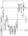
図5から図9は、管理装置60に実装されたプログラム64、65、66、67、サーバ70、80に実装されたサーバプログラム75、85、及び端末装置90に実装された端末プログラム104等の各プログラムが実行する処理を示すフローチャートである。すなわち、図5から図9には、生産管理システム10において行われる処理が示されている。具体的には、図5は、製造予定、元情報、及び解析情報をデータベースに登録する処理を示すフローチャートである。図6は、リアルタイム表示画面を表示させる処理を示すフローチャートである。図7は、集計表示画面を表示させる処理を示すフローチャートである。図8は、解析情報表示画面を表示させる処理を示すフローチャートである。図9は、今期累計表示画面を表示させる処理を示すフローチャートである。
5 to 9 show the
また、図10及び図11は、端末装置90のディスプレイ107或いはタッチパネル109に表示されるリアルタイム表示画面の一部をそれぞれ示す図である。なお、図11は、図10におけるリアルタイム表示画面のスクロールバーを操作することによって表示される部分である。
Further, FIGS. 10 and 11 are diagrams showing a part of the real-time display screen displayed on the display 107 or
図12は、端末装置90のディスプレイ107或いはタッチパネル109に表示される集計表示画面を示す図である。図13は、端末装置90のディスプレイ107或いはタッチパネル109に表示される解析情報表示画面を示す図である。図14は、端末装置90のディスプレイ107或いはタッチパネル109に表示される今期累計表示画面を示す図である。
FIG. 12 is a diagram showing a total display screen displayed on the display 107 or
以下、図5から図14が参照されて生産管理システム10において実行される処理が説明される。
Hereinafter, the processes executed in the
管理担当者等は、入力装置108やタッチパネル109を用いて端末装置90に製造予定を入力する。端末装置90は、入力された製造予定を管理装置60に送信する。図5が示すように、管理装置60の第2プログラム65或いは上記管理プログラムは、管理装置60が製造予定を受信したことに基づいて(S11:Yes)、製造予定を製造予定データベースに登録する(S12)。第2プログラム65或いは上記管理プログラムは、管理装置60が製造予定を受信しない場合(S11:No)、ステップS12の処理をスキップする。
A person in charge of management or the like inputs the manufacturing schedule into the
一方、PLC50は、製造経時情報を取得し、当該製造経時情報を上記付設メモリに保存するとともに(S31)、製造経時情報に装置ID及び取得日時を付して元情報として管理装置60に送信する(S32)。PLC50は、終了と判断するまで(S33:No)、所定の時間間隔(サンプリング間隔)でステップS31、S32の処理を繰り返し実行する。PLC50は、例えば電源がオフとされたことに基づいて、或いは終了指示が入力されたことに基づいて終了と判断し(S33:Yes)、処理を終了する(エンド)。
On the other hand, the
管理装置60は、PLC50が送信した元情報を受信する(S32)。管理装置60の第1プログラム64は、受信した元情報を登録要求とともに第1サーバ70に送信する(S14)。当該登録要求は、例えばコマンドである。ステップS14の処理は、特許請求の範囲に記載された「元情報登録処理」に相当する。
The
第1サーバ70は、管理装置60が送信した元情報及び登録要求を受信する(S14)。第1サーバ70の第1サーバプログラム75は、受信した登録要求にしたがって、元情報を元情報データベースに登録する(S15)。
The
一方、管理装置60の第3プログラム66は、元情報の解析を行って解析情報を生成するため、製造予定を製造予定データベースから読み出す(S21)。第3プログラム66は、読み出した製造予定から、解析の対象とする製造装置30を示す装置ID及び工程コードを特定し、特定した装置ID及び工程コードを含む解析用情報の要求を第1サーバ70に送信する(S22)。当該要求は、例えばコマンドである。ステップS21の処理は、特許請求の範囲に記載された「製造予定取得処理」に相当する。
On the other hand, the
第1サーバ70は、管理装置60が送信した要求を受信する(S22)。第1サーバ70の第1サーバプログラム75は、受信した要求に含まれる装置ID及び工程コードと一致する装置ID及び工程コードを有するレコードを元情報データベース(図3(B)参照)において特定し、特定したレコードに含まれる製造経時情報を読み出す(S23)。第1サーバプログラム75は、読み出した製造経時情報(元情報)と、レコードの特定に用いた装置ID及び工程コードとを含む解析用情報を、ステップS22で受信した要求の応答として管理装置60に返信する(S24)。
The
なお、第1サーバ70が返信する解析用情報に含まれる製造経時情報は、上記サンプリング周期ごとに取得される全ての製造経時情報であってもよいし、当該全ての製造経時情報からいくつかの製造経時情報を間引いた間引き後の製造経時情報であってもよい。
Note that the manufacturing time information included in the analysis information returned by the
管理装置60は、第1サーバ70が返信した解析用情報を受信する(S24)。管理装置60の第3プログラム66は、受信した解析用情報に基づいて上記解析情報(図4(A))を生成する(S25)。具体的には、第3プログラム66は、製造経時情報に含まれる各フラグに基づいて製造装置30の状態を特定し、製造経時情報に含まれるエラーコードに基づいてエラー種別を特定し、製造経時情報に含まれる日時に基づいて始点時刻や終点時刻や期間や日付を特定する。第3プログラム66が解析用情報の要求を送信して(S22)解析用情報を受信するステップS24の処理は、特許請求の範囲に記載された「エラー情報取得処理」に相当する。解析用情報が有する製造経時情報の「日時」は、特許請求の範囲に記載された「エラーの発生日時」に相当する。ステップS25の処理は、特許請求の範囲に記載された「解析情報生成処理」に相当する。
The
管理装置60の第3プログラム66は、生成した解析情報及び装置IDを含む登録要求を第1サーバ70に送信する(S26)。当該登録要求は、例えば、含まれる解析情報を解析情報データベースに登録することを指示するコマンドである。ステップS26の処理は、特許請求の範囲に記載された「解析情報登録処理」に相当する。
The
なお、解析用情報の要求の送信(S21)及び解析情報の登録要求の送信(S26)は、第3プログラム66に代えて第1プログラム64が行ってもよい。すなわち、第1サーバ70との通信は、第1プログラム64が一括で行ってもよい。その場合、例えば第3プログラム66がOS68を通じて解析用情報の要求の送信(S21)及び解析情報の登録要求の送信(S26)を第1プログラム64に指示する。
Note that the sending of the request for analysis information (S21) and the sending of the request for registering analysis information (S26) may be performed by the
第1サーバ70は、解析情報を含む上記登録要求を受信する(S26)。第1サーバ70の第1サーバプログラム75は、受信した登録要求にしたがって、解析情報データベースに新たなレコードを生成し、解析情報を登録する(S27)。
The
一方、管理装置60の第2プログラム65は、ステップS32において管理装置60が受信した元情報に基づいて稼働時間や生産数量や目標達成率や稼働割合等を算出し、集計データベースに登録する(S28)。
On the other hand, the
次に、図6に基づいて、端末装置90のディスプレイ107やタッチパネル109にリアルタイム表示画面を表示させる処理について説明がされる。
Next, based on FIG. 6, a process for displaying a real-time display screen on the display 107 or
管理担当者等は、端末装置90において端末プログラム104を起動させる。管理担当者等は、例えば端末プログラム104がディスプレイ107やタッチパネル109に表示させたホーム画面(不図示)において、リアルタイム表示画面の表示を指示するアイコンを選択する。
A person in charge of management or the like starts the
端末プログラム104は、リアルタイム表示画面の表示を指示するアイコンの選択を受け付けたことに応じて(S41)、リアルタイム表示画面データの要求を管理装置60に送信する(S42)。当該要求は、例えば工場の種類(本社工場或いは地方工場)を示す工場識別情報と、画面の種類(リアルタイム表示画面)を示す画面識別情報を含むコマンドである。
In response to receiving the selection of the icon instructing the display of the real-time display screen (S41), the
管理装置60は、リアルタイム表示画面データの要求を受信する(S42)。管理装置60の第2プログラム65は、当該要求に含まれる工場識別情報と一致する工場識別情報を有するレコードを製造予定データベース(図3(A)参照)において特定し、特定したレコードの情報(製造予定)を読み出す(S43)。第2プログラム65は、読み出した製造予定と、ステップS32(図5参照)において受信した元情報とに基づいて、リアルタイム表示画面データを生成する(S44)。リアルタイム表示画面データは、図10及び図11に示すリアルタイム表示画面をディスプレイ107やタッチパネル109に表示させるための画面データである。
The
図10及び図11が示すように、リアルタイム表示画面は、複数の装置アイコン120を備える。一の装置アイコン120は、一の製造装置30に対応しており、当該製造装置30の名称である製造装置名を有している。図10及び図11が示す例では、製造装置名は、「A01」や「集中クーラント」や「B02」や「C04」や「D02」や「洗浄機」などである。なお、「A01」や「B02」や「C04」や「D02」は、上記装置IDであってもよい。
As shown in FIGS. 10 and 11, the real-time display screen includes a plurality of device icons 120. One device icon 120 corresponds to one
リアルタイム表示画面は、複数の表示エリア130に、線等によって仕切られている。一の表示エリア130は、一のエリア40(図2参照)に対応している。具体的には、表示エリア131(130)は「円筒」エリア41に対応している。表示エリア132(130)は「クーラント」エリア42に対応している。表示エリア133(130)は「幅・外径」エリア43に対応している。表示エリア134(130)は「内径」エリア44に対応している。表示エリア135(130)は「仕上」エリア45に対応している。表示エリア136(130)は「洗浄機」エリア46に対応している。各表示エリア130は、製造工場20における各エリア40の配置位置と同じ配置位置でリアルタイム表示画面内に配置されている。
The real-time display screen is partitioned into a plurality of display areas 130 by lines or the like. One display area 130 corresponds to one area 40 (see FIG. 2). Specifically, the display area 131 (130) corresponds to the "cylindrical"
「円筒」を示す名称オブジェクト123が表示エリア131に配置されている。「クーラント」を示す名称オブジェクト124が表示エリア132に配置されている。「幅・外径」を示す名称オブジェクト125が表示エリア133に配置されている。「内径」を示す名称オブジェクト126が表示エリア134に配置されている。「仕上」を示す名称オブジェクト127が表示エリア135に配置されている。「洗浄機」を示す名称オブジェクト128が表示エリア136に配置されている。名称オブジェクト123、124、125、126、127、128は、各表示エリア130がどの表示エリアであるかを管理担当者等に認識させる。
A
装置アイコン120は、各表示エリア130にそれぞれ配置されている。装置アイコン120は、付された製造装置名が示す製造装置30が製造工場20内で配置されたエリア40及び位置に対応する表示エリア130及び位置に配置されている。図10が示す例では、製造装置名「A01」を付された装置アイコン120は、表示エリア131の左上に配置されている。そして、装置ID「A01」を有する製造装置30(図2参照)は、表示エリア131に対応する「円筒」エリア41の左上に配置されている。
The device icons 120 are arranged in each display area 130, respectively. The device icon 120 is placed in the display area 130 and position corresponding to the
リアルタイム表示画面を視認した管理担当者等は、装置アイコン120が表示された位置により、装置アイコン120に対応する製造装置30を直感的に認識することができる。また、確認したい製造装置30に対応する装置アイコン120を、多数の装置アイコン120のなかから容易に探し出すことができる。すなわち、管理担当者等は、製造状況の確認を素早くかつ的確に行うことができる。
A person in charge of management who visually checks the real-time display screen can intuitively recognize the
装置アイコン120は、製造装置名に加え、元情報及び製造予定の一部の情報を有する。図10が示す例では、元情報の一部の情報は、現在製造(加工や検査等)を行っている製品の名称(商品コード)、稼働時間、及び現在までの製造数量であり、製造予定の一部の情報は、製造予定数量である。図10において製造装置名「A01」を有する装置アイコン120では、現在製造を行っている製品の名称は「A000003」であり、次に製造する製品の名称は「C000020」であり、稼働時間は「4:51:15」であり、現在までの製造数量は「911」であり、製造予定数量は「3187」である。 The device icon 120 includes original information and some information about the manufacturing schedule in addition to the manufacturing device name. In the example shown in Figure 10, some of the information in the original information is the name (product code) of the product currently being manufactured (processing, inspection, etc.), operating time, and the manufacturing quantity to date, and the manufacturing schedule. Some of the information is the planned production quantity. In FIG. 10, in the equipment icon 120 with the manufacturing equipment name "A01", the name of the product currently being manufactured is "A000003", the name of the product to be manufactured next is "C000020", and the operating time is " 4:51:15'', the production quantity to date is ``911'', and the planned production quantity is ``3187''.
また、装置アイコン120は、元情報及び製造予定に基づく情報を有する。図10が示す例では、元情報及び製造予定に基づく情報は、目標達成率(%)である。目標達成率(%)は、現在までの製造数量を製造予定数量で除して100を乗じた値(%表示)である。図10において製造装置名「A01」を有する装置アイコン120では、目標達成率(%)は「28.6%」である。なお、装置アイコン120は、図10が示す情報の他、他の元情報や製造予定やその他の情報を有していてもよい。 Further, the device icon 120 has information based on original information and a manufacturing schedule. In the example shown in FIG. 10, the information based on the original information and the manufacturing schedule is the target achievement rate (%). The target achievement rate (%) is the value (expressed as a %) obtained by dividing the production quantity to date by the planned production quantity and multiplying it by 100. In FIG. 10, the target achievement rate (%) of the device icon 120 having the manufacturing device name “A01” is “28.6%”. In addition to the information shown in FIG. 10, the device icon 120 may include other source information, manufacturing schedule, and other information.
装置アイコン120が有する稼働時間や現在までの製造数量は、上記製造経時情報である。すなわち、装置アイコン120は、製造装置30の現在の状況をリアルタイムで表示するオブジェクトである。そして、複数の装置アイコン120を有するリアルタイム表示画面は、製造工場20における全ての製造装置30の現在の状況を一括して表示する。
The operating time and the current production quantity that the device icon 120 has are the above-mentioned manufacturing elapsed information. That is, the device icon 120 is an object that displays the current status of the
また、装置アイコン120は、集計表示画面(図12参照)の表示を管理担当者等が指示するためのオブジェクトでもある。装置アイコン120が選択されることにより、集計表示画面がポップアップ表示される。「ポップアップ表示」とは、リアルタイム表示画面とは別のウインドウに表示されることを意味する。 The device icon 120 is also an object used by a management person or the like to instruct display of the total display screen (see FIG. 12). When the device icon 120 is selected, a total display screen pops up. "Pop-up display" means displaying in a window separate from the real-time display screen.
リアルタイム表示画面は、表示切替アイコン140をさらに備える。表示切替アイコン140は、リアルタイム表示画面と今期累計表示画面(図14参照)との間で表示を切り替える指示を管理担当者等が入力するためのオブジェクトである。 The real-time display screen further includes a display switching icon 140. The display switching icon 140 is an object for a management person or the like to input an instruction to switch the display between the real-time display screen and the current period cumulative display screen (see FIG. 14).
また、リアルタイム表示画面は、業務終了アイコン141をさらに備える。業務終了アイコン141は、リアルタイム表示画面の表示を終了させる指示を端末装置90に入力するためのオブジェクトである。
Further, the real-time display screen further includes a task completion icon 141. The task end icon 141 is an object for inputting an instruction to the
第2プログラム65によるリアルタイム表示画面データの生成(S44)について詳しく説明がされる。第2プログラム65は、リアルタイム表示画面データを生成するためのフォーマットデータを予め有する。フォーマットデータは、第2プログラム65の一部であってもよいし、第2プログラム65とは別にメモリ62に記憶されていてもよい。また、当該フォーマットデータは、リアルタイム表示画面を示す上記画面識別情報と対応付けられている。
Generation of real-time display screen data (S44) by the
フォーマットデータは、製品の名称、稼働時間、現在までの製造数量、製造予定数量、及び目標達成率(%)の1つがそれぞれ入力される複数の入力フィールドを有する。第2プログラム65は、ステップS43で読み出した製造予定及びステップS32で受信した元情報と、製造予定及び元情報から算出した目標達成率(%)とを上記入力フィールドに入力してリアルタイム表示画面データを生成する。なお、フォーマットデータは、製品の名称等を引数とし、リアルタイム表示画面データを戻り値とする関数であってもよいし、インスタンスとしてリアルタイム表示画面データを生成するクラスであってもよい。すなわち、フォーマットデータは、リアルタイム表示画面データを生成するための元となるデータであればよい。
The format data has a plurality of input fields into which one of the product name, operating time, current production quantity, planned production quantity, and target achievement rate (%) is input. The
管理装置60の第2プログラム65は、生成したリアルタイム表示画面データを、ステップS42で受信した要求の応答として、端末装置90に返信する(S45)。
The
端末装置90は、管理装置60が返信したリアルタイム表示画面データを受信する(S45)。端末装置90の端末プログラム104は、受信したリアルタイム表示画面データが示すリアルタイム表示画面をディスプレイ107或いはタッチパネル109に表示させる(S46)。例えば、端末プログラム104は、リアルタイム表示画面データを示すファイルパスを含むコマンドをOS106に入力することによって、リアルタイム表示画面をディスプレイ107或いはタッチパネル109に表示させる。
The
端末プログラム104は、例えばリアルタイム表示画面データの要求(S42)を管理装置60に定期的に送信し、リアルタイム表示画面を定期的に更新する。或いは、管理装置60の第2プログラム65は、リアルタイム表示画面データの要求を受けたことに基づいて、端末装置90から停止要求がされるまで、端末装置90にリアルタイム表示画面データを定期的に送信してもよい。
The
なお、上記フォーマットデータは、端末装置90のメモリ102に記憶されていてもよい。その場合、第2プログラム65は、ステップS43で読み出した製造予定及びステップS32(図5参照)で受信した元情報と、製造予定及び元情報から算出した目標達成率(%)とを端末装置90に送信する。端末装置90の端末プログラム104は、受信した元情報、製造予定、及び目標達成率(%)を上記フォーマットデータに入力してリアルタイム表示画面データを生成してディスプレイ107或いはタッチパネル109に表示させる。
Note that the above format data may be stored in the
管理装置60のプログラム64、65、66、67は、終了指示が入力されるまで(S49:No)、S11(図5参照)以降の処理を繰り返し実行する。終了指示は、例えば休業日前やメンテナンス前において行われる。プログラム64、65、66、67は、終了指示が入力されたと判断すると(S49:Yes)、処理を終了する(エンド)。第2プログラム65が繰り返し実行するステップS44の処理は、特許請求の範囲に記載された「生成処理」に相当する。第2プログラム65が繰り返し実行するステップS45の処理は、特許請求の範囲に記載された「第1送信処理」に相当する。
The
同様に、第1サーバ70の第1サーバプログラム75は、終了指示が入力されるまで、或いは第1サーバ70の電源がオフにされるまで(S50:No)、S15(図5参照)以降の処理を繰り返し実行する。終了指示は、例えば休業日前やメンテナンス前において行われる。第1サーバプログラム75は、終了指示が入力されたと判断すると(S50:Yes)、処理を終了する(エンド)。
Similarly, the
次に、管理担当者等がリアルタイム表示画面(図10参照)において装置アイコン120を選択して集計表示画面(図12参照)がポップアップ表示される場合の処理について説明がされる。 Next, a description will be given of a process when a management person or the like selects the device icon 120 on the real-time display screen (see FIG. 10) and a total display screen (see FIG. 12) is displayed as a pop-up.
端末装置90の端末プログラム104は、リアルタイム表示画面(図10参照)において装置アイコン120や表示切替アイコン140が選択されたか否かを判断する(S47)。端末プログラム104は、アイコン120、140が選択されていないと判断すると(S47:No)、終了指示が入力されたか否かを判断する(S51)。終了指示は、業務終了アイコン141が選択され、或いはリアルタイム表示画面の右上の「×」が選択されたことによって端末装置90に入力される。端末プログラム104は、終了指示が入力されていないと判断すると(S51:No)、ステップS42以降の処理を繰り返し実行する。すなわち、端末プログラム104は、リアルタイム表示画面を更新表示する。端末プログラム104は、終了指示が入力されたと判断すると(S51:Yes)、処理を終了する(エンド)。
The
端末装置90の端末プログラム104は、ステップS47においてアイコン120、140が選択されたと判断すると(S47:Yes)、選択されたアイコンが装置アイコン120であるか表示切替アイコン140であるかを判断する(S48)。端末プログラム104は、選択されたアイコンが装置アイコン120であると判断すると(S48:装置アイコン)、集計表示画面(図12参照)をディスプレイ107或いはタッチパネル109にポップアップ表示させる処理(図7参照)を実行する。
When the
図12が示す集計表示画面は、概ね集計データベース(図4(B)参照)と同様の表である。集計表示画面は、複数の行及び複数の列を有している。当該複数の列は、集計データベースと同様の項目「日付」や項目「稼働時間」等を付されている。集計表示画面の各行は、「2021/10/25」などの日付によって相互に識別される。すなわち、各行は、管理担当者等が指定した装置アイコン120に表示された「A01」等の製造装置名を有する製造装置30が、「2021/10/25」等が示す各日付において、日中の稼働時間や夜間の稼働時間や合計の稼働時間や日中の製造数量や夜間の製造数量や合計の製造数量や目標達成率等を示す。
The total display screen shown in FIG. 12 is a table similar to the total database (see FIG. 4(B)). The total display screen has multiple rows and multiple columns. The plurality of columns are labeled with items such as "date" and "operating hours" similar to those in the aggregation database. Each row of the total display screen is mutually identified by a date such as "2021/10/25". In other words, each row indicates that the
以下では、項目「稼働割合 日中・夜間」など、集計データベース(図4(B)参照)に示されていない項目について説明する。 Below, items that are not shown in the aggregate database (see FIG. 4(B)), such as the item "operation ratio daytime/nighttime", will be explained.
項目「稼働割合 日中・夜間」が付された列は、2つのサブ列を有している。一方のサブ列の各フィールドには、日中の全時間に対する稼働時間の割合(%)が表示される。他方のサブ列の各フィールドは、夜間の全時間に対する稼働時間の割合(%)が表示される。 The column with the item "Occupancy ratio daytime/nighttime" has two sub-columns. Each field in one sub-column displays the ratio (%) of operating time to the total time during the day. Each field in the other sub-column displays the ratio (%) of operating time to the total nighttime hours.
項目「異常停止累積時間」が付された列の各フィールドには、エラーによって製造装置30の正常な稼働が停止されていた時間、すなわち異常停止していた時間の総計が表示される。項目「通常停止累積時間」が付された列の各フィールドには、例えば一の製品の製造から他の製品の製造に切り替えるための準備等によって製造が停止されている時間の総計が表示される。項目「異常発生回数」が付された列の各フィールドには、その日にエラー(異常)が発生した回数が表示される。項目「初回生産時間」が付された列の各フィールドには、例えば製造開始からウォーミングアップ時間を含めて最初の製品が製造されるまでに要した時間が表示される。項目「サイクルタイム(秒)」が付された列の各フィールドには、1つの製品の製造に要する時間が表示される。
Each field in the column labeled with the item "cumulative abnormal stop time" displays the total amount of time during which the normal operation of the
集計表示画面は、「グラフ」アイコン142及び「閉じる」アイコン143をさらに備える。「グラフ」アイコン142は、解析情報表示画面(図13参照)を表示させる指示を受け付けるオブジェクトである。「閉じる」アイコン143は、集計表示画面を閉じる指示を受け付けるオブジェクトである。なお、集計表示画面を閉じる指示は、集計表示画面の右上の「×」によって受け付けてもよい。 The total display screen further includes a "graph" icon 142 and a "close" icon 143. The "graph" icon 142 is an object that accepts an instruction to display an analysis information display screen (see FIG. 13). The “close” icon 143 is an object that accepts an instruction to close the total display screen. Note that the instruction to close the tally display screen may be accepted by clicking the "x" in the upper right corner of the tally display screen.
図7が参照されて、端末装置90の端末プログラム104が上記集計表示画面を端末装置90のディスプレイ107或いはタッチパネル109に表示させる処理について説明がされる。
With reference to FIG. 7, a process in which the
まず、端末プログラム104は、集計表示画面データの要求を管理装置60に送信する(S52)。当該要求は、例えば集計表示画面データの返信を指示するコマンドである。当該コマンドは、管理担当者等が選択した装置アイコン120に対応する装置IDと、画面の種類(集計表示画面)を示す画面識別情報と、工場識別情報とを含む。
First, the
管理装置60は、端末装置90が送信した上記要求を受信する(S52)。管理装置60の第2プログラム65は、受信した要求に含まれる装置ID及び工場識別情報を含む登録情報の返信要求を第2サーバ80に送信する(S54)。当該要求は、例えば装置ID及び工場識別情報を含むコマンドである。
The
第2サーバ80の第2サーバプログラム85は、受信した返信要求に含まれる装置ID及び工場識別情報と一致する装置ID及び工場識別情報を有するレコードを集計データベース(図4(B)参照)において特定し、特定したレコードが有する情報(登録情報)を読み出す(S55)。第2サーバプログラム85は、読み出した登録情報を管理装置60に返信する(S56)。
The
管理装置60は、第2サーバ80が返信した登録情報を受信する(S56)。管理装置60の第2プログラム65は、受信した登録情報を、上記画面識別情報が示すフォーマットデータの入力フィールドに入力し、集計表示画面データを生成する(S57)。第2プログラム65は、生成した集計表示画面データを、ステップS52で受信した要求の応答として端末装置90に返信する(S58)。ステップS57の処理は、特許請求の範囲に記載された「集計表示画面データ生成処理」に相当する。ステップS58の処理は、特許請求の範囲に記載された「第2送信処理」に相当する。
The
なお、上記フォーマットデータは、端末装置90のメモリ102に記憶されていてもよい。その場合、第2プログラム65は、ステップS43で読み出した登録情報を、ステップS53で受信した要求の応答として端末装置90に返信する。端末装置90の端末プログラム104は、受信した登録情報を上記フォーマットデータに入力して集計表示画面を生成する。
Note that the above format data may be stored in the
端末装置90は、管理装置60が返信した集計表示画面データを受信する(S58)。端末装置90の端末プログラム104は、受信した集計表示画面データをディスプレイ107或いはタッチパネル109に入力し、集計表示画面をポップアップ表示させる(S59)。
The
次に、管理担当者等が集計表示画面(図12参照)においてグラフアイコン142或いは閉じるアイコン143を選択した場合の処理について説明がされる。 Next, a description will be given of the processing when the administrator or the like selects the graph icon 142 or the close icon 143 on the total display screen (see FIG. 12).
端末装置90の端末プログラム104は、集計表示画面においてグラフアイコン142或いは閉じるアイコン143が選択されたか否かを判断する(S60)。端末プログラム104は、アイコン142、143が選択されるまで(S60:No)、集計表示画面を継続して表示する(S59)。なお、閉じるアイコン143の選択には、集計表示画面の右上の「×」の選択も含まれるものとする。端末プログラム104は、アイコン142、或いはアイコン143が選択されたと判断すると(S60:Yes)、選択されたアイコンが閉じるアイコン143(或いは「×」)が選択されたかグラフアイコン142が選択されたかを判断する(S61)。端末プログラム104は、閉じるアイコン143(或いは「×」)が選択されたと判断すると、集計表示画面(図12参照)を閉じ(S62)、リアルタイム表示画面を表示させるステップS42以降の処理(図6参照)を実行する。なお、端末プログラム104は、集計表示画面を閉じることを指示するコマンドをOS106に入力することによって集計表示画面を閉じる。
The
端末装置90の端末プログラム104は、ステップS61において、グラフアイコン142が選択されたと判断すると(S61:グラフ)、解析情報表示画面(図13)を表示させる処理(図8参照)を実行する。
When the
図13が示す解析情報表示画面は、管理担当者等が指定した製造装置30について解析情報をグラフで表示する画面である。解析情報表示画面は、製造装置名を示す装置名オブジェクト144と、年月オブジェクト145と、グラフ146とを有する。装置名オブジェクト144が表示する製造装置名は、リアルタイム表示画面(図10参照)において管理担当者等が選択した装置アイコン120が有する製造装置名と同一である。年月オブジェクト145は、現在の年及び月を表示する。図示例では、年月オブジェクト145は、2021年10月を示す「2021/10」である。
The analysis information display screen shown in FIG. 13 is a screen that displays analysis information in the form of a graph regarding the
グラフ146は、縦軸147、横軸148、及び複数のバー149を有する。縦軸147は、年月オブジェクト145が示す月における各日付を示す。図示例では、10月26日が「10-26」で示され、10月25日が「10-25」で示されている。横軸148は、時間を示す。図13における横軸の左端の「0」は0時を示し、「1」は1時を示し、「23」は23時を示し、「23」の右隣りの「0」は翌日の0時を示す。 Graph 146 has a vertical axis 147, a horizontal axis 148, and a plurality of bars 149. The vertical axis 147 indicates each date in the month indicated by the year/month object 145. In the illustrated example, October 26th is shown as "10-26" and October 25th is shown as "10-25". A horizontal axis 148 indicates time. "0" at the left end of the horizontal axis in FIG. 13 indicates 0 o'clock, "1" indicates 1 o'clock, "23" indicates 23 o'clock, and "0" to the right of "23" indicates 0 o'clock the next day. shows.
「10-26」等の各日付に対してそれぞれ1つのバー149が表示されている。すなわち、一のバー149は、一の日付における解析情報を示している。また、バー149は、停止状態を示す部分、準備状態を示す部分、稼働状態を示す部分、異常停止状態を示す部分等の複数の部分を有する。各部分は、色やハッチングなどによって相互に識別可能とされている。停止状態、準備状態、稼働状態、及び異常停止状態は、解析情報データベース(図4(A)参照)の解析情報における項目「状態」に登録される状態に一致する情報である。図4(A)に示す例では、項目「状態」に異常停止が登録されたレコードにおいて、項目「始点時刻」に対応するフィールドに「13:12」が登録されており、項目「終点時刻」に対応するフィールドに「13:43」が登録されており、項目「期間」に対応するフィールドに「31分」が登録されている。その場合、図13が示す解析情報表示画面において、バー149における異常停止状態を示す部分の一方の端(左端)は、横軸が示す時間が13時12分である所に位置し、他方の端(右端)は、横軸が示す時間が13時43分である所に位置する。そして、上記異常停止状態を示す部分の長さは、期間「31分」に対応する長さとなる。 One bar 149 is displayed for each date such as "10-26". That is, one bar 149 indicates analysis information on one date. Moreover, the bar 149 has a plurality of parts, such as a part showing a stopped state, a part showing a preparation state, a part showing an operating state, and a part showing an abnormal stop state. Each part is mutually distinguishable by color, hatching, etc. The stop state, preparation state, operating state, and abnormal stop state are information that match the states registered in the item "state" in the analysis information of the analysis information database (see FIG. 4(A)). In the example shown in FIG. 4(A), in a record in which abnormal stop is registered in the item "Status", "13:12" is registered in the field corresponding to the item "Starting point time", and "13:12" is registered in the field corresponding to the item "Starting point time", and "13:12" is registered in the field corresponding to the item "Starting point time". "13:43" is registered in the field corresponding to the item "period", and "31 minutes" is registered in the field corresponding to the item "period". In that case, in the analysis information display screen shown in FIG. 13, one end (left end) of the part of the bar 149 indicating the abnormal stop state is located at the time indicated by the horizontal axis, which is 13:12, and the other end is located at the time indicated by the horizontal axis, 13:12. The end (right end) is located where the time indicated by the horizontal axis is 13:43. The length of the portion indicating the abnormal stop state is the length corresponding to the period "31 minutes".
以下、端末装置90のディスプレイ107或いはタッチパネル109に解析情報表示画面が表示される処理について、図8が参照されて説明がされる。
The process of displaying the analysis information display screen on the display 107 or
端末装置90の端末プログラム104は、解析情報表示表示画面データの要求を管理装置60に送信する(S71)。当該要求は、例えば解析情報表示画面データの返信を指示するコマンドである。当該コマンドは、管理担当者等が選択した装置アイコン120に対応する装置IDと、解析情報表示画面を示す画面識別情報とを含む。
The
管理装置60は、端末装置90が送信した上記要求を受信する(S71)。管理装置60の第2プログラム65は、当該要求を受信したことに基づいて、第4プログラム67を起動させ、解析情報表示画面データの生成を指示する(S72)。例えば、第2プログラム65は、第4プログラム67を示す第4プログラムID、自己を示す第2プログラムID、装置ID、及び画面識別情報を含むコマンドをOS68に入力する。OS68は、第4プログラムIDが示す第4プログラム67を起動させるとともに、第4プログラム67に上記装置ID、上記画面識別情報、及び第2プログラムIDを受け渡す。ステップS72の処理は、特許請求の範囲に記載された「指示処理」に相当する。解析情報画面を示す画面識別情報は、特許請求の範囲に記載された「解析情報表示画面データの生成を指示する情報」に相当する。
The
起動された第4プログラム67は、受け渡された装置IDが示す製造装置30について、画面識別情報が示す解析情報表示画面データを生成する。
The activated
詳しく説明すると、第4プログラム67は、解析情報の返信要求を第1サーバ70に送信する(S73)。当該返信要求は、例えば上記装置IDを含むコマンドである。
To explain in detail, the
第1サーバ70は、管理装置60が送信した返信要求を受信する(S73)。第1サーバ70の第1サーバプログラム75は、受信した返信要求に含まれる装置IDと一致する装置IDを有するレコードを解析情報データベース(図4(A)参照)において特定する。そして、第1サーバプログラム75は、特定したレコードが有する解析情報を読み出す(S74)。第1サーバプログラム75は、読み出した解析情報を、ステップS73で受信した返信要求に対する応答として管理装置60に返信する(S75)。
The
管理装置60は、第1サーバ70が返信した解析情報を受信する(S75)。管理装置60の第4プログラム67は、解析情報表示画面データを生成するためのフォーマットデータであって、解析情報表示画面を示す画面識別情報と対応付けられたフォーマットデータを予め有する。当該フォーマットデータは、CSS及びJavascriptを含むhtml形式のデータであって、製造装置名や解析情報(図4(A)参照)が入力される入力フィールドを有している。すなわち、解析情報表示画面(図13参照)は、いわゆるWebページである。第4プログラム67は、ステップS75で受信した解析情報を上記フォーマットデータの入力フィールドに入力し、解析情報表示画面データを生成する(S76)。このフォーマットデータは、上記関数やクラスであってもよい。
The
管理装置60の第4プログラム67は、生成した解析情報表示画面データを示すファイルパス及び第2プログラムIDをOS68に返す。OS68は、第2プログラムIDが示す第2プログラム65に上記ファイルパスを受け渡す。第2プログラム65は、受け渡されたファイルパスが示す解析情報表示画面データを、ステップS71で受信した要求の応答として返信する(S77)。すなわち、端末装置90との通信は、第2プログラム65が一括して行う。
The
なお、第4プログラム67が第1サーバ70に解析情報の要求を送信して解析情報を取得する例が説明されたが、第1サーバ70への解析情報の要求の送信は、第3プログラム66が行ってもよい。すなわち、第1サーバ70との通信は、第3プログラム66が一括して行ってもよい。その場合、解析情報表示画面データの要求を受信した第2プログラム65は(S71)、解析情報表示画面を示す画面識別情報を第3プログラム66に受け渡す。第3プログラム66は、受け渡された画面識別情報を含む解析情報の要求を第1サーバ70に送信し(S74)、第1サーバ70が返信した解析情報を受信する(S75)。第3プログラム66は、受信した解析情報を示すファイルパスを第2プログラム65に受け渡す。第2プログラム65は、第4プログラム67をOS68を通じて起動させ、受け渡されたファイルパス、画面識別情報、及び第2プログラムIDを第4プログラム67に受け渡す。そして、第2プログラム66は、第4プログラム67が生成した解析情報表示画面データを示すファイルパスをOS68を通じて第4プログラム67から受け取る。
Although an example has been described in which the
また、第2プログラム65が端末装置90に解析情報表示画面データを返信する例が説明されたが、第4プログラム67が解析情報表示画面データを端末装置90に直接返信してもよい。例えば、端末プログラム104が送信した解析情報表示画面データ(Webページデータ)の要求を第4プログラム67が受け付けて当該解析情報表示画面データ(Webページデータ)を生成し、端末装置90に返信してもよい。すなわち、第4プログラム67にも端末装置90と通信を行う機能が実装されていてもよい。
Further, although an example has been described in which the
端末装置90は、管理装置60が返信した解析情報表示画面データを受信する(S77)。端末装置90の端末プログラム104は、受信した解析情報表示画面データをディスプレイ107或いはタッチパネル109にポップアップ表示させることを、OS106を通じてブラウザ105に指示する。ブラウザ105は、解析情報表示画面データをディスプレイ107或いはタッチパネル109にポップアップ表示させる(S78)。なお、端末プログラム104がブラウザ105のプラグインプログラムである場合、端末プログラム104は、解析情報表示画面データをディスプレイ107或いはタッチパネル109にポップアップ表示させる指示(コマンド)をOS106に直接入力する。
The
端末装置90の端末プログラム104は、終了指示が入力されたか否かを判断する(S79)。終了指示は、例えば画面右上の「×」によって入力される。端末プログラム104は、終了指示が入力されるまで(S79:No)、解析情報表示画面をディスプレイ107或いはタッチパネル109に表示させる(S78)。端末プログラム104は、終了指示が入力されたことに基づいて(S79:Yes)、解析情報表示画面を閉じ(S80)、集計表示画面を表示させるステップS59以降の処理(図7参照)を実行する。
The
次に、管理担当者等がリアルタイム表示画面(図10参照)において表示切替アイコン140を選択することによって表示される今期累計表示画面(図14参照)、及び今期累計表示画面を表示させる処理について説明がされる。 Next, we will explain the current term cumulative display screen (see Figure 14), which is displayed when the administrator etc. selects the display switching icon 140 on the real-time display screen (see Figure 10), and the process of displaying the current term cumulative display screen. is done.
図14が示すように、今期累計表示画面は、リアルタイム表示画面(図10参照)と同一のレイアウトを有する画面である。今期累計表示画面は、リアルタイム表示画面における装置アイコン120に代えて装置アイコン121を有する。装置アイコン121の配置位置や形状は装置アイコン120と同一である。装置アイコン121は、装置アイコン120とは異なり、現在の製造状況ではなく、今期の累計を表示する。 As shown in FIG. 14, the current period cumulative display screen is a screen having the same layout as the real-time display screen (see FIG. 10). The current term cumulative display screen has a device icon 121 instead of the device icon 120 on the real-time display screen. The arrangement position and shape of the device icon 121 are the same as those of the device icon 120. The device icon 121 differs from the device icon 120 in that it displays not the current manufacturing status but the cumulative total for the current period.
詳しく説明すると、装置アイコン121は、現在製造(加工や検査等)を行っている製品の名称、今期累計稼働時間、今期累計製造数量、今期製造予定数量、及び今期目標達成率(%)を有している。今期累計稼働時間は、四半期や半期などの所定の期間(今期)における稼働時間の累計である。今期累計製造数量は、当該所定の期間における製造数量の累計である。今期製造予定数量は、当該所定の期間における製造予定数量の累計である。今期目標達成率(%)は、今期製造数量を今期製造予定数量で除して100を乗じた値(%表示)である。図14において製造装置名「A01」を有する装置アイコン121では、現在製造を行っている製品の名称は「A000003」であり、今期累計稼働時間は「1153:16:57」であり、今期累計製造数量は「175521」であり、今期製造予定数量は「369692」であり、今期目標達成率(%)は「47.5%」である。なお、装置アイコン121は、今期累計稼働時間、今期累計製造数量、今期製造予定数量、及び今期目標達成率(%)以外の情報を有していてもよい。 To explain in detail, the equipment icon 121 includes the name of the product currently being manufactured (processing, inspection, etc.), the cumulative operating time of this fiscal year, the cumulative manufacturing quantity of this fiscal year, the planned manufacturing quantity of this fiscal year, and the target achievement rate (%) of this fiscal year. are doing. The current term's cumulative operating hours are the cumulative operating hours in a predetermined period (current term) such as a quarter or a half-year. The cumulative production quantity for the current period is the cumulative production quantity for the predetermined period. The planned production quantity for the current period is the cumulative total of the planned production quantity for the predetermined period. The current term target achievement rate (%) is the value (expressed as a %) obtained by dividing the current term's production quantity by the current term's planned production quantity and multiplying it by 100. In the equipment icon 121 with the manufacturing equipment name "A01" in FIG. 14, the name of the product currently being manufactured is "A000003", the cumulative operating time of the current period is "1153:16:57", and the cumulative manufacturing time of the current period is "1153:16:57". The quantity is "175,521", the planned production quantity for this term is "369,692", and the target achievement rate (%) for this term is "47.5%". Note that the device icon 121 may have information other than the cumulative operating time of this term, the cumulative production quantity of this term, the planned production quantity of this term, and the target achievement rate (%) of this term.
装置アイコン121が有する今期稼働時間や今期製造数量は、上記製造経時情報である。すなわち、装置アイコン121は、製造装置30における今期の稼働状況を表示する表示オブジェクトである。なお、装置アイコン121が選択された場合は、装置アイコン120が選択された場合と同様に、集計表示画面(図12参照)が端末装置90のディスプレイ107或いはタッチパネル109に表示される。
The current period operating time and current period production quantity that the device icon 121 has are the above-mentioned manufacturing elapsed information. That is, the device icon 121 is a display object that displays the operating status of the
次に、今期累計表示画面を表示させる処理について説明がされる。図6が示すように、端末装置90の端末プログラム104は、リアルタイム表示画面(図10参照)において管理担当者等によって選択されたアイコンが表示切替アイコン140であると判断すると(S48:切替アイコン)、図9が示す処理を実行する。まず、端末プログラム104は、累計表示画面データの要求を管理装置60に送信する(S81)。当該要求は、例えば今期累計表示画面を示す画面識別情報及び上記工場識別情報を含むコマンドである。
Next, the process of displaying the current term cumulative display screen will be explained. As shown in FIG. 6, when the
管理装置60は、端末装置90が送信した要求を受信する(S81)。管理装置60の第2プログラム65は、受信した要求に今期累計表示画面を示す画面識別情報が含まれることに基づいて、製造予定の返信要求を第2サーバ80に送信する(S82)。当該返信要求は、例えば要求する情報の種別及び工場識別情報を含むコマンドである。
The
第2サーバ80は、製造予定の返信要求を受信する(S82)。第2サーバ80の第2サーバプログラム85は、受信した返信要求に含まれる工場識別情報と一致する工場識別情報を有するレコードを集計データベース(図4(B))において特定し、特定したレコードが有する情報を読み出す。第2サーバプログラム85は、読み出した情報に基づいて、製造装置30ごとに、今期累計稼働時間及び今期累計製造数量を算出して取得する(S83)。なお、集計データベースに予め算出された今期累計稼働時間及び今期累計製造数量が登録されている場合は、第2サーバプログラム85は、今期累計稼働時間及び今期累計製造数量を集計データベースから読み出して取得する(S83)。なお、図9のステップS83では、今期累計稼働時間及び今期累計製造数量をまとめて集計情報と記載している。この集計情報は、今期累計稼働時間及び今期累計製造数量を算出するための算出用情報であってもよい。その場合、今期累計稼働時間及び今期累計製造数量は、集計情報に基づいて管理装置60の第2プログラム65によって算出される。
The
第2サーバ80の第2サーバプログラム85は、取得した集計情報を、ステップS82で受信した返信要求の応答として管理装置60に返信する(S84)。管理装置60は、第2サーバ80が返信した集計情報を受信する(S84)。
The
管理装置60の第2プログラム65は、ステップS81で受信した要求に含まれる工場識別情報と一致する工場識別情報を有するレコードを製造予定データベースにおいて特定する。そして、第2プログラム65は、特定したレコードから情報を読み出し、読み出した情報に基づいて、製造装置30ごとに、今期製造予定数量を算出して取得する(S85)。なお、製造予定データベースに今期製造予定数量が予め登録されている場合、第2プログラム65は、今期製造予定数量を製造予定データベースから読み出して取得する(S85)。
The
管理装置60の第2プログラム65は、取得した今期累計製造数量及び今期製造予定数量に基づいて、製造装置30ごとに、上記今期目標達成率(%)を算出する(S86)。第2プログラム65は、取得した今期累計稼働時間、今期累計製造数量、今期製造予定数量、及び今期目標達成率(%)に基づいて、今期累計表示画面データを生成する(S87)。
The
詳しく説明すると、管理装置60の第2プログラム65は、今期累計表示画面データを生成するためのフォーマットデータを予め有する。当該フォーマットデータは、今期累計稼働時間、今期累計製造数量、今期製造予定数量、及び今期目標達成率(%)等を入力する入力フィールドを有する。第2プログラム65は、当該フォーマットデータの各入力フィールドに今期累計稼働時間、今期累計製造数量、今期製造予定数量、及び今期目標達成率(%)を入力して今期累計表示画面データを生成する。なお、当該フォーマットデータは、上記関数やクラスであってもよい。
To explain in detail, the
管理装置60の第2プログラム65は、生成した今期累計表示画面データを、ステップS81で受信した返信要求の応答として、端末装置90に返信する(S88)。
The
端末装置90は、管理装置60が返信した今期累計表示画面データを受信する(S88)。端末装置90の端末プログラム104は、受信した今期累計表示画面データをディスプレイ107或いはタッチパネル109に入力し、今期累計表示画面をディスプレイ107或いはタッチパネル109に表示させる(S89)。
The
端末装置90の端末プログラム104は、終了指示が入力されたか否かを判断する(S90)。終了指示は、業務終了アイコン141が選択され、或いは今期累計表示画面の右上の「×」が選択されたことによって端末装置90に入力される。端末プログラム104は、終了指示が入力されたと判断すると(S90:Yes)、処理を終了する(エンド)。端末プログラム104は、終了指示が入力されていないと判断すると(S90:No)、表示切替アイコン140が選択されたか否かを判断する(S91)。端末プログラム104は、表示切替アイコン140が選択されていないと判断すると(S91:No)、ステップS81以降の処理を再度実行する。すなわち、今期累計表示画面が所定の時間間隔で更新表示される。端末プログラム104は、表示切替アイコン140が選択されたと判断すると(S91:Yes)、リアルタイム表示画面を更新表示するためのステップS42(図6参照)以降の処理を再度実行する。
The
[実施形態の作用効果] [Operations and effects of embodiment]
本実施形態では、第2プログラム65により、PLC50が取得した元情報を統括してリアルタイムで端末装置90に表示可能であり、かつ第1プログラム64及び第3プログラム66により、元情報を統括して解析して解析情報を生成することができる。
In this embodiment, the
例えば第2プログラム65が解析情報表示画面データを生成する場合、解析情報表示画面データの生成が遅延したり当該生成に不具合が生じたりした場合に、端末装置90における製造経時情報のリアルタイム表示にも支障が生じるおそれがある。本実施形態では、第4プログラム67が解析情報表示画面データを生成するから、製造経時情報のリアルタイム表示に支障を及ぼすことなく、解析情報を端末装置90に表示させることができる。
For example, when the
本実施形態では、解析情報表示画面(図13参照)において表示される解析情報は、製造予定データベースに登録された情報(製造予定)と、元情報データベースに登録された製造経時情報とに基づいて生成される。したがって、製造経時情報のみによって解析情報を生成するよりも詳細な解析情報を生成することができる。 In this embodiment, the analysis information displayed on the analysis information display screen (see FIG. 13) is based on the information (manufacturing schedule) registered in the manufacturing schedule database and the manufacturing elapsed information registered in the original information database. generated. Therefore, more detailed analysis information can be generated than when analysis information is generated only based on manufacturing elapsed information.
本実施形態では、第2プログラム65により、1日ごとに集計した集計データを有する集計表示画面を端末装置90に表示させることができる。
In this embodiment, the
リアルタイム表示画面において、管理担当者等によって装置アイコン120が選択されると、選択された装置アイコン120が示す製造装置30について、エラーの発生日時を示す解析情報表示画面が表示される。したがって、管理担当者等は、エラーの発生日時などの詳細を製造装置30ごとに確認することができる。
When a device icon 120 is selected by a person in charge of management or the like on the real-time display screen, an analysis information display screen showing the date and time of occurrence of an error is displayed for the
本実施形態では、第1サーバ70としてRedisサーバを用いることにより、元情報データベースへの元情報の登録及び元情報データベースからの解析用情報の読み出しを高速で行うことができる。
In this embodiment, by using a Redis server as the
本実施形態では、解析情報表示画面がWebページであるから、ブラウザ105などの既存のプログラムやシステムを利用して解析情報表示画面を端末装置90に容易にポップアップ表示させることができる。
In this embodiment, since the analysis information display screen is a Web page, the analysis information display screen can be easily displayed as a pop-up on the
[変形例] [Modified example]
上述の実施形態では、管理を行う管理装置60が1つの装置である例が説明された。もっとも、管理装置60は、複数の装置で構成されていてもよい。そして、プログラム64、65、66、67は、複数の装置に分散して実装されていてもよい。
In the embodiments described above, an example has been described in which the
10・・・生産管理システム
11・・・通信ネットワーク
20・・・製造工場
30・・・製造装置
50・・・PLC
60・・・管理装置
62、72、74、82、84、102・・・メモリ
64・・・第1プログラム
65・・・第2プログラム
66・・・第3プログラム
67・・・第4プログラム
70・・・第1サーバ
75・・・第1サーバプログラム
80・・・第2サーバ
85・・・第2サーバプログラム
90・・・端末装置
104・・・端末プログラム
120・・・装置アイコン
121・・・装置アイコン
10...
60...
Claims (7)
第1プログラム、第2プログラム、及び第3プログラムを実装する管理装置と、
元情報データベース及び解析情報データベースを記憶するメモリと、
端末装置と、を備え、
上記コントローラ、上記管理装置、及び上記端末装置は、通信ネットワークを通じて通信可能であり、
上記第1プログラムは、
上記元情報を上記コントローラから取得して上記元情報データベースに登録させる元情報登録処理を実行し、
上記第2プログラムは、
上記元情報を定期的に取得してリアルタイム表示画面データを定期的に生成する生成処理と、
上記リアルタイム表示画面データを上記端末装置に定期的に送信する第1送信処理と、を実行し、
上記第3プログラムは、
上記エラー情報が示すエラーの発生日時を上記元情報データベースから取得するエラー情報取得処理と、
上記装置ID及び上記発生日時を対応付けた解析情報を生成する解析情報生成処理と、
上記解析情報を上記解析情報データベースに登録させる解析情報登録処理と、を実行する、生産管理システム。 a plurality of controllers that periodically acquire original information including at least device ID, manufacturing elapsed information, and error information;
a management device that implements a first program, a second program, and a third program;
a memory for storing a source information database and an analysis information database;
comprising a terminal device;
The controller, the management device, and the terminal device are capable of communicating through a communication network,
The first program above is
Executing a source information registration process that acquires the source information from the controller and registers it in the source information database;
The second program above is
A generation process that periodically acquires the above source information and periodically generates real-time display screen data;
a first transmission process of periodically transmitting the real-time display screen data to the terminal device;
The third program above is
an error information acquisition process that acquires the date and time of occurrence of the error indicated by the error information from the source information database;
an analysis information generation process that generates analysis information in which the device ID and the date and time of occurrence are associated with each other;
A production management system that executes analysis information registration processing for registering the analysis information in the analysis information database.
上記解析情報生成処理は、
上記製造予定データベースから上記装置ID及び製造予定を取得する製造予定取得処理と、
上記解析情報及び上記製造予定に基づいて、上記製品IDと、上記装置IDと、上記エラー情報と、エラー発生日時と、上記製造予定とを対応付けた上記解析情報を生成する処理と、を含む、請求項1または2に記載の生産管理システム。 The memory further stores a manufacturing schedule database in which at least a product ID, the device ID, and a manufacturing schedule are associated with each other,
The above analysis information generation process is
a manufacturing schedule acquisition process that acquires the device ID and manufacturing schedule from the manufacturing schedule database;
a process of generating, based on the analysis information and the manufacturing schedule, the analysis information in which the product ID, the device ID, the error information, the date and time of error occurrence, and the manufacturing schedule are associated with each other; , The production management system according to claim 1 or 2.
上記第2プログラムは、
上記集計情報に基づいて集計表示画面データを生成する集計表示画面データ生成処理と、
上記集計表示画面データを上記端末装置に送信する第2送信処理と、をさらに実行する、請求項1から3のいずれかに記載の生産管理システム。 The memory further stores a tally database in which tally information that is a tally of the manufacturing time information for each day is registered;
The second program above is
a tally display screen data generation process that generates tally display screen data based on the tally information;
The production management system according to any one of claims 1 to 3, further executing a second transmission process of transmitting the total display screen data to the terminal device.
上記第2プログラムは、
上記装置アイコンが選択されたことに基づいて、選択された当該装置アイコンと対応付けられた上記装置ID、及び上記解析情報表示画面データの生成を指示する情報を上記第4プログラムに受け渡す指示処理をさらに実行する、請求項2に記載の生産管理システム。 The real-time display screen shown by the above-mentioned real-time display screen data includes multiple device icons,
The second program above is
Based on the selection of the device icon, an instruction process for passing the device ID associated with the selected device icon and information instructing generation of the analysis information display screen data to the fourth program. The production management system according to claim 2, further performing:
3. The production management system according to claim 2, wherein the analysis information display screen data is web page data displayed by a browser installed in the terminal device.
Priority Applications (1)
| Application Number | Priority Date | Filing Date | Title |
|---|---|---|---|
| JP2022068162A JP7812510B2 (en) | 2022-04-18 | 2022-04-18 | Production Management System |
Applications Claiming Priority (1)
| Application Number | Priority Date | Filing Date | Title |
|---|---|---|---|
| JP2022068162A JP7812510B2 (en) | 2022-04-18 | 2022-04-18 | Production Management System |
Publications (2)
| Publication Number | Publication Date |
|---|---|
| JP2023158366A true JP2023158366A (en) | 2023-10-30 |
| JP7812510B2 JP7812510B2 (en) | 2026-02-10 |
Family
ID=88509300
Family Applications (1)
| Application Number | Title | Priority Date | Filing Date |
|---|---|---|---|
| JP2022068162A Active JP7812510B2 (en) | 2022-04-18 | 2022-04-18 | Production Management System |
Country Status (1)
| Country | Link |
|---|---|
| JP (1) | JP7812510B2 (en) |
Cited By (1)
| Publication number | Priority date | Publication date | Assignee | Title |
|---|---|---|---|---|
| CN118101428A (en) * | 2024-04-24 | 2024-05-28 | 浪潮云信息技术股份公司 | A redis chain replication fault detection and repair method and device |
Citations (6)
| Publication number | Priority date | Publication date | Assignee | Title |
|---|---|---|---|---|
| JP2003005816A (en) * | 2001-06-22 | 2003-01-08 | Toshiba Electronic Engineering Corp | Method for accumulating equipment operating state data and system thereof |
| JP2004164023A (en) * | 2002-11-08 | 2004-06-10 | Toshiba Mach Co Ltd | Device, system, method, and program for supporting management, and recording medium with the program recorded thereon |
| JP2012160056A (en) * | 2011-02-01 | 2012-08-23 | Denso Corp | Manufacturing line monitoring system |
| JP2017102668A (en) * | 2015-12-01 | 2017-06-08 | オムロン株式会社 | Management system and management program |
| US20170263104A1 (en) * | 2016-03-10 | 2017-09-14 | Boe Technology Group Co., Ltd. | Production equipment monitoring method and system |
| WO2020240937A1 (en) * | 2019-05-29 | 2020-12-03 | 新東工業株式会社 | Information processing system, gateway, server, and information processing method |
-
2022
- 2022-04-18 JP JP2022068162A patent/JP7812510B2/en active Active
Patent Citations (9)
| Publication number | Priority date | Publication date | Assignee | Title |
|---|---|---|---|---|
| JP2003005816A (en) * | 2001-06-22 | 2003-01-08 | Toshiba Electronic Engineering Corp | Method for accumulating equipment operating state data and system thereof |
| JP2004164023A (en) * | 2002-11-08 | 2004-06-10 | Toshiba Mach Co Ltd | Device, system, method, and program for supporting management, and recording medium with the program recorded thereon |
| JP3946618B2 (en) * | 2002-11-08 | 2007-07-18 | 東芝機械株式会社 | MANAGEMENT SUPPORT DEVICE, ITS SYSTEM, ITS METHOD, ITS PROGRAM, AND RECORDING MEDIUM CONTAINING THE PROGRAM |
| JP2012160056A (en) * | 2011-02-01 | 2012-08-23 | Denso Corp | Manufacturing line monitoring system |
| JP5601231B2 (en) * | 2011-02-01 | 2014-10-08 | 株式会社デンソー | Production line monitoring system |
| JP2017102668A (en) * | 2015-12-01 | 2017-06-08 | オムロン株式会社 | Management system and management program |
| JP6540481B2 (en) * | 2015-12-01 | 2019-07-10 | オムロン株式会社 | Management system and management program |
| US20170263104A1 (en) * | 2016-03-10 | 2017-09-14 | Boe Technology Group Co., Ltd. | Production equipment monitoring method and system |
| WO2020240937A1 (en) * | 2019-05-29 | 2020-12-03 | 新東工業株式会社 | Information processing system, gateway, server, and information processing method |
Cited By (1)
| Publication number | Priority date | Publication date | Assignee | Title |
|---|---|---|---|---|
| CN118101428A (en) * | 2024-04-24 | 2024-05-28 | 浪潮云信息技术股份公司 | A redis chain replication fault detection and repair method and device |
Also Published As
| Publication number | Publication date |
|---|---|
| JP7812510B2 (en) | 2026-02-10 |
Similar Documents
| Publication | Publication Date | Title |
|---|---|---|
| US11675344B2 (en) | Systems and methods for maintaining equipment in an industrial automation environment | |
| US12461513B2 (en) | Visualization system | |
| US6006171A (en) | Dynamic maintenance management system | |
| EP3751373B1 (en) | Predictive troubleshooting for abnormal plant operations | |
| US6539271B2 (en) | Quality management system with human-machine interface for industrial automation | |
| US20080098007A1 (en) | Distributed Traceability Management System | |
| DE102004036300A1 (en) | Economic description in a process control system | |
| US20030023408A1 (en) | System for collecting and storing information | |
| JP6702180B2 (en) | Maintenance management device, maintenance management method, maintenance management program, and recording medium | |
| JP6597579B2 (en) | Device asset management apparatus, device asset management method, device asset management program, and recording medium | |
| CN101833329A (en) | Asset optimization reporting in the process plant | |
| US10235447B2 (en) | Method and system for co-operative intelligent HMIs for effective process operations | |
| US20180181923A1 (en) | Maintenance management device, maintenance management method, and non-transitory computer readable storage medium | |
| Poór et al. | Predictive maintenance as an intelligent service in Industry 4.0. | |
| JP7812510B2 (en) | Production Management System | |
| CN114626954A (en) | Intelligent manufacturing cooperative system | |
| US20080027976A1 (en) | Process Management System and Computer Readable Recording Medium | |
| KR102409863B1 (en) | Method, server and program for providing robot prevention and prediction measure service | |
| DE112021008103T5 (en) | INCIDENT ASSISTANCE DEVICE AND INCIDENT MANAGEMENT SYSTEM | |
| JP2002073158A (en) | Remote monitoring/diagnosing system | |
| JP7812511B2 (en) | Production Management System | |
| US11675347B2 (en) | Industrial machine monitoring device | |
| Ngukhiew et al. | Real Time Production Status Monitoring System | |
| EP1873601A1 (en) | Processing management system | |
| EP3633476A1 (en) | Method and device for transmitting machine information to a service device |
Legal Events
| Date | Code | Title | Description |
|---|---|---|---|
| A621 | Written request for application examination |
Free format text: JAPANESE INTERMEDIATE CODE: A621 Effective date: 20250314 |
|
| A977 | Report on retrieval |
Free format text: JAPANESE INTERMEDIATE CODE: A971007 Effective date: 20251128 |
|
| A131 | Notification of reasons for refusal |
Free format text: JAPANESE INTERMEDIATE CODE: A131 Effective date: 20251216 |
|
| A521 | Request for written amendment filed |
Free format text: JAPANESE INTERMEDIATE CODE: A523 Effective date: 20260109 |
|
| TRDD | Decision of grant or rejection written | ||
| A01 | Written decision to grant a patent or to grant a registration (utility model) |
Free format text: JAPANESE INTERMEDIATE CODE: A01 Effective date: 20260120 |
|
| A61 | First payment of annual fees (during grant procedure) |
Free format text: JAPANESE INTERMEDIATE CODE: A61 Effective date: 20260120 |
|
| R150 | Certificate of patent or registration of utility model |
Ref document number: 7812510 Country of ref document: JP Free format text: JAPANESE INTERMEDIATE CODE: R150 |