JP2023123731A - Medicine sorting device - Google Patents
Medicine sorting device Download PDFInfo
- Publication number
- JP2023123731A JP2023123731A JP2023106073A JP2023106073A JP2023123731A JP 2023123731 A JP2023123731 A JP 2023123731A JP 2023106073 A JP2023106073 A JP 2023106073A JP 2023106073 A JP2023106073 A JP 2023106073A JP 2023123731 A JP2023123731 A JP 2023123731A
- Authority
- JP
- Japan
- Prior art keywords
- medicine
- returned
- drug
- unit
- storage
- Prior art date
- Legal status (The legal status is an assumption and is not a legal conclusion. Google has not performed a legal analysis and makes no representation as to the accuracy of the status listed.)
- Granted
Links
- 239000003814 drug Substances 0.000 title claims abstract description 2159
- 229940079593 drug Drugs 0.000 title claims abstract description 622
- 238000003860 storage Methods 0.000 claims abstract description 574
- 238000012545 processing Methods 0.000 claims abstract description 136
- 238000012546 transfer Methods 0.000 claims description 67
- 230000007246 mechanism Effects 0.000 claims description 42
- 238000003384 imaging method Methods 0.000 claims description 38
- 230000032258 transport Effects 0.000 claims description 4
- 238000001179 sorption measurement Methods 0.000 description 138
- 238000000034 method Methods 0.000 description 100
- 239000003708 ampul Substances 0.000 description 90
- 239000011347 resin Substances 0.000 description 54
- 229920005989 resin Polymers 0.000 description 54
- 238000010586 diagram Methods 0.000 description 38
- 238000001514 detection method Methods 0.000 description 35
- 238000005286 illumination Methods 0.000 description 35
- 238000004458 analytical method Methods 0.000 description 34
- 230000003287 optical effect Effects 0.000 description 24
- 230000036544 posture Effects 0.000 description 21
- 238000004364 calculation method Methods 0.000 description 20
- 230000006870 function Effects 0.000 description 20
- 238000002360 preparation method Methods 0.000 description 12
- 238000003708 edge detection Methods 0.000 description 10
- 230000002093 peripheral effect Effects 0.000 description 10
- 238000013459 approach Methods 0.000 description 8
- 230000001965 increasing effect Effects 0.000 description 7
- 230000005484 gravity Effects 0.000 description 6
- 239000000463 material Substances 0.000 description 6
- 230000007723 transport mechanism Effects 0.000 description 6
- 230000003028 elevating effect Effects 0.000 description 5
- 230000000052 comparative effect Effects 0.000 description 4
- 238000012790 confirmation Methods 0.000 description 4
- 238000013016 damping Methods 0.000 description 4
- 230000007423 decrease Effects 0.000 description 4
- 239000000284 extract Substances 0.000 description 4
- 238000002483 medication Methods 0.000 description 4
- 238000003825 pressing Methods 0.000 description 4
- 239000000126 substance Substances 0.000 description 4
- 238000003197 gene knockdown Methods 0.000 description 3
- 238000007726 management method Methods 0.000 description 3
- 238000006243 chemical reaction Methods 0.000 description 2
- 238000007596 consolidation process Methods 0.000 description 2
- 230000003247 decreasing effect Effects 0.000 description 2
- 230000001934 delay Effects 0.000 description 2
- 238000003795 desorption Methods 0.000 description 2
- 238000006073 displacement reaction Methods 0.000 description 2
- 230000000694 effects Effects 0.000 description 2
- 230000002452 interceptive effect Effects 0.000 description 2
- 230000001678 irradiating effect Effects 0.000 description 2
- 230000009191 jumping Effects 0.000 description 2
- 239000012466 permeate Substances 0.000 description 2
- 239000011295 pitch Substances 0.000 description 2
- 238000011084 recovery Methods 0.000 description 2
- 238000005096 rolling process Methods 0.000 description 2
Images


Classifications
-
- A—HUMAN NECESSITIES
- A61—MEDICAL OR VETERINARY SCIENCE; HYGIENE
- A61J—CONTAINERS SPECIALLY ADAPTED FOR MEDICAL OR PHARMACEUTICAL PURPOSES; DEVICES OR METHODS SPECIALLY ADAPTED FOR BRINGING PHARMACEUTICAL PRODUCTS INTO PARTICULAR PHYSICAL OR ADMINISTERING FORMS; DEVICES FOR ADMINISTERING FOOD OR MEDICINES ORALLY; BABY COMFORTERS; DEVICES FOR RECEIVING SPITTLE
- A61J3/00—Devices or methods specially adapted for bringing pharmaceutical products into particular physical or administering forms
-
- A—HUMAN NECESSITIES
- A61—MEDICAL OR VETERINARY SCIENCE; HYGIENE
- A61J—CONTAINERS SPECIALLY ADAPTED FOR MEDICAL OR PHARMACEUTICAL PURPOSES; DEVICES OR METHODS SPECIALLY ADAPTED FOR BRINGING PHARMACEUTICAL PRODUCTS INTO PARTICULAR PHYSICAL OR ADMINISTERING FORMS; DEVICES FOR ADMINISTERING FOOD OR MEDICINES ORALLY; BABY COMFORTERS; DEVICES FOR RECEIVING SPITTLE
- A61J1/00—Containers specially adapted for medical or pharmaceutical purposes
- A61J1/05—Containers specially adapted for medical or pharmaceutical purposes for collecting, storing or administering blood, plasma or medical fluids ; Infusion or perfusion containers
- A61J1/06—Ampoules or carpules
-
- A—HUMAN NECESSITIES
- A61—MEDICAL OR VETERINARY SCIENCE; HYGIENE
- A61J—CONTAINERS SPECIALLY ADAPTED FOR MEDICAL OR PHARMACEUTICAL PURPOSES; DEVICES OR METHODS SPECIALLY ADAPTED FOR BRINGING PHARMACEUTICAL PRODUCTS INTO PARTICULAR PHYSICAL OR ADMINISTERING FORMS; DEVICES FOR ADMINISTERING FOOD OR MEDICINES ORALLY; BABY COMFORTERS; DEVICES FOR RECEIVING SPITTLE
- A61J7/00—Devices for administering medicines orally, e.g. spoons; Pill counting devices; Arrangements for time indication or reminder for taking medicine
- A61J7/0069—Trays for holding or distributing medicines
-
- F—MECHANICAL ENGINEERING; LIGHTING; HEATING; WEAPONS; BLASTING
- F21—LIGHTING
- F21V—FUNCTIONAL FEATURES OR DETAILS OF LIGHTING DEVICES OR SYSTEMS THEREOF; STRUCTURAL COMBINATIONS OF LIGHTING DEVICES WITH OTHER ARTICLES, NOT OTHERWISE PROVIDED FOR
- F21V33/00—Structural combinations of lighting devices with other articles, not otherwise provided for
- F21V33/0064—Health, life-saving or fire-fighting equipment
-
- G—PHYSICS
- G06—COMPUTING; CALCULATING OR COUNTING
- G06K—GRAPHICAL DATA READING; PRESENTATION OF DATA; RECORD CARRIERS; HANDLING RECORD CARRIERS
- G06K19/00—Record carriers for use with machines and with at least a part designed to carry digital markings
- G06K19/06—Record carriers for use with machines and with at least a part designed to carry digital markings characterised by the kind of the digital marking, e.g. shape, nature, code
- G06K19/06009—Record carriers for use with machines and with at least a part designed to carry digital markings characterised by the kind of the digital marking, e.g. shape, nature, code with optically detectable marking
- G06K19/06018—Record carriers for use with machines and with at least a part designed to carry digital markings characterised by the kind of the digital marking, e.g. shape, nature, code with optically detectable marking one-dimensional coding
- G06K19/06028—Record carriers for use with machines and with at least a part designed to carry digital markings characterised by the kind of the digital marking, e.g. shape, nature, code with optically detectable marking one-dimensional coding using bar codes
-
- G—PHYSICS
- G06—COMPUTING; CALCULATING OR COUNTING
- G06K—GRAPHICAL DATA READING; PRESENTATION OF DATA; RECORD CARRIERS; HANDLING RECORD CARRIERS
- G06K7/00—Methods or arrangements for sensing record carriers, e.g. for reading patterns
- G06K7/10—Methods or arrangements for sensing record carriers, e.g. for reading patterns by electromagnetic radiation, e.g. optical sensing; by corpuscular radiation
- G06K7/10544—Methods or arrangements for sensing record carriers, e.g. for reading patterns by electromagnetic radiation, e.g. optical sensing; by corpuscular radiation by scanning of the records by radiation in the optical part of the electromagnetic spectrum
- G06K7/10712—Fixed beam scanning
- G06K7/10722—Photodetector array or CCD scanning
- G06K7/10732—Light sources
-
- G—PHYSICS
- G06—COMPUTING; CALCULATING OR COUNTING
- G06K—GRAPHICAL DATA READING; PRESENTATION OF DATA; RECORD CARRIERS; HANDLING RECORD CARRIERS
- G06K7/00—Methods or arrangements for sensing record carriers, e.g. for reading patterns
- G06K7/10—Methods or arrangements for sensing record carriers, e.g. for reading patterns by electromagnetic radiation, e.g. optical sensing; by corpuscular radiation
- G06K7/14—Methods or arrangements for sensing record carriers, e.g. for reading patterns by electromagnetic radiation, e.g. optical sensing; by corpuscular radiation using light without selection of wavelength, e.g. sensing reflected white light
- G06K7/1404—Methods for optical code recognition
- G06K7/1408—Methods for optical code recognition the method being specifically adapted for the type of code
- G06K7/1413—1D bar codes
-
- G—PHYSICS
- G06—COMPUTING; CALCULATING OR COUNTING
- G06Q—INFORMATION AND COMMUNICATION TECHNOLOGY [ICT] SPECIALLY ADAPTED FOR ADMINISTRATIVE, COMMERCIAL, FINANCIAL, MANAGERIAL OR SUPERVISORY PURPOSES; SYSTEMS OR METHODS SPECIALLY ADAPTED FOR ADMINISTRATIVE, COMMERCIAL, FINANCIAL, MANAGERIAL OR SUPERVISORY PURPOSES, NOT OTHERWISE PROVIDED FOR
- G06Q10/00—Administration; Management
- G06Q10/08—Logistics, e.g. warehousing, loading or distribution; Inventory or stock management
- G06Q10/087—Inventory or stock management, e.g. order filling, procurement or balancing against orders
-
- G—PHYSICS
- G06—COMPUTING; CALCULATING OR COUNTING
- G06V—IMAGE OR VIDEO RECOGNITION OR UNDERSTANDING
- G06V10/00—Arrangements for image or video recognition or understanding
- G06V10/40—Extraction of image or video features
- G06V10/46—Descriptors for shape, contour or point-related descriptors, e.g. scale invariant feature transform [SIFT] or bags of words [BoW]; Salient regional features
-
- G—PHYSICS
- G07—CHECKING-DEVICES
- G07F—COIN-FREED OR LIKE APPARATUS
- G07F11/00—Coin-freed apparatus for dispensing, or the like, discrete articles
- G07F11/46—Coin-freed apparatus for dispensing, or the like, discrete articles from movable storage containers or supports
- G07F11/60—Coin-freed apparatus for dispensing, or the like, discrete articles from movable storage containers or supports the storage containers or supports being rectilinearly movable
-
- G—PHYSICS
- G07—CHECKING-DEVICES
- G07F—COIN-FREED OR LIKE APPARATUS
- G07F17/00—Coin-freed apparatus for hiring articles; Coin-freed facilities or services
- G07F17/0092—Coin-freed apparatus for hiring articles; Coin-freed facilities or services for assembling and dispensing of pharmaceutical articles
-
- G—PHYSICS
- G07—CHECKING-DEVICES
- G07F—COIN-FREED OR LIKE APPARATUS
- G07F9/00—Details other than those peculiar to special kinds or types of apparatus
- G07F9/002—Vending machines being part of a centrally controlled network of vending machines
-
- H—ELECTRICITY
- H04—ELECTRIC COMMUNICATION TECHNIQUE
- H04N—PICTORIAL COMMUNICATION, e.g. TELEVISION
- H04N23/00—Cameras or camera modules comprising electronic image sensors; Control thereof
- H04N23/56—Cameras or camera modules comprising electronic image sensors; Control thereof provided with illuminating means
-
- A—HUMAN NECESSITIES
- A61—MEDICAL OR VETERINARY SCIENCE; HYGIENE
- A61J—CONTAINERS SPECIALLY ADAPTED FOR MEDICAL OR PHARMACEUTICAL PURPOSES; DEVICES OR METHODS SPECIALLY ADAPTED FOR BRINGING PHARMACEUTICAL PRODUCTS INTO PARTICULAR PHYSICAL OR ADMINISTERING FORMS; DEVICES FOR ADMINISTERING FOOD OR MEDICINES ORALLY; BABY COMFORTERS; DEVICES FOR RECEIVING SPITTLE
- A61J2205/00—General identification or selection means
- A61J2205/10—Bar codes
-
- A—HUMAN NECESSITIES
- A61—MEDICAL OR VETERINARY SCIENCE; HYGIENE
- A61J—CONTAINERS SPECIALLY ADAPTED FOR MEDICAL OR PHARMACEUTICAL PURPOSES; DEVICES OR METHODS SPECIALLY ADAPTED FOR BRINGING PHARMACEUTICAL PRODUCTS INTO PARTICULAR PHYSICAL OR ADMINISTERING FORMS; DEVICES FOR ADMINISTERING FOOD OR MEDICINES ORALLY; BABY COMFORTERS; DEVICES FOR RECEIVING SPITTLE
- A61J2205/00—General identification or selection means
- A61J2205/40—General identification or selection means by shape or form, e.g. by using shape recognition
Abstract
Description
本発明は、薬剤仕分装置に関する。 The present invention relates to a drug sorting device.
患者に処方された薬剤が、処方変更等の理由により医療機関内の薬剤処方を管理する部
署に返却される場合がある(返品薬剤)。特許文献1には、返品薬剤の処理作業の効率化
と、この作業におけるヒューマンエラー防止のための、返品薬剤を自動的に認識して格納
する返品薬剤仕分装置を開示している。
A drug prescribed to a patient may be returned to a department that manages drug prescription within a medical institution due to a prescription change or the like (returned drug).
一般に、返品薬剤は、種類、形状、大きさ、使用期限等の性状が種々異なる。しかし、
特許文献1に開示されたものを含め、従来の返品薬剤仕分装置では、性状が種々異なる返
品薬剤をその後の払出作業の効率等の要因を考慮した高い自由度を確保して格納すること
について、特段の考慮が払われていない。より具体的には、性状が種々異なる返品薬剤を
、例えば処方情報に応じた自由な払い出しが可能となるように、高い自由度を確保して格
納することについて、特段の考慮が払われていない。
In general, returned medicines have various properties such as type, shape, size, expiration date, and the like. but,
Regarding the conventional returned medicine sorting apparatus, including the one disclosed in
また、特許文献1の返品薬剤仕分装置は、返品薬剤の画像を撮影し、その輪郭を解析す
ることにより返品薬剤の位置を検出する。そして、検出した位置に基づいて返品薬剤を吸
着して移送し、格納場所に自動的に返却する。しかし、移送すべき返品薬剤の位置等を認
識する際、返品薬剤同士が接触している場合や部分的に重なり合っている場合、その輪郭
が不明瞭となり、1つの薬剤の位置を正確に検出できない場合がある。
Further, the returned-medicine sorting apparatus of
さらに、特許文献1の装置では、返品薬剤を格納する返品薬収納部を備えている。返品
薬収納部は返品薬剤の種類毎に区分された複数の収納カセットを有しており、返品薬収納
部から引き出された収納カセットに、返品薬剤が仕分けされて格納されるようになってい
る。このため、特許文献1の装置では、返品薬剤の種類毎に収納カセットを必要とするた
め、多数の収納カセットを必要とする。さらに、返品薬剤を格納するときに収納カセット
を返品薬収納部から引き出すためのスペースを必要とする。この結果、返品薬収納部が大
型化してしまう。一方、従来のアンプル払出装置の格納部は、薬種毎に専用のカセットが
備えられ、薬剤師により取り出されて蓋を開けて1本ずつ収納されるという運用がなされ
ている。このため、カセットごとに収容容器、蓋、排出機構が搭載されるため、1つのカ
セットが大型され、それが何種も搭載されるため、さらに大型化されている。
Furthermore, the apparatus of
そこで、本発明の第1の課題は、種類、形状、大きさ、使用期限等の性状が種々異なり
、かつ非整列状態で供給された薬剤を、自動的に認識して高い自由度を確保して格納する
ことである。
Therefore, the first object of the present invention is to automatically recognize medicines of various properties such as types, shapes, sizes, expiration dates, etc., and supplied in a non-aligned state to ensure a high degree of freedom. to store it.
また、本発明の第2の課題は、薬剤同士が接触している場合や部分的に重なり合ってい
る場合でも、正確に1つの薬剤の位置を検出できる薬剤仕分装置を提供することである。
A second object of the present invention is to provide a drug sorting apparatus that can accurately detect the position of one drug even when the drugs are in contact with each other or partially overlapped.
さらに、本発明の第3の課題は、薬剤を仕分けして格納する格納部を、コンパクト化す
ることである。
Furthermore, a third object of the present invention is to make a storage section for sorting and storing medicines compact.
第1の課題を解決するための本発明の第1の態様は、薬剤の向き及び姿勢と、形状、大
きさ、種類、使用期限のような薬剤の性状とを認識することが可能な認識部と、少なくと
も前記認識部で認識された薬剤の大きさに応じて格納時に前記薬剤について設定される格
納領域と、前記薬剤の識別情報とを関連付けて前記薬剤を配置し、それによって前記薬剤
を取出可能に格納する格納部と、前記認識部で認識された前記薬剤の性状に基づいて前記
薬剤が取り扱い対象であるか否かを判定可能な判定処理部と、を有する、薬剤仕分装置を
提供する。
A first aspect of the present invention for solving the first problem is a recognition unit capable of recognizing the direction and posture of a drug and properties of the drug such as shape, size, type, and expiration date. and storing the medicine by associating the storage area set for the medicine at the time of storage according to the size of the medicine recognized at least by the recognition unit and the identification information of the medicine, thereby retrieving the medicine. and a determination processing unit capable of determining whether or not the medicine is to be handled based on the properties of the medicine recognized by the recognition unit. .
認識部は、薬剤の向き、姿勢、及び性状(種類、形状、大きさ、使用期限等を含む)を
認識する。格納部には、少なくとも認識部で認識された大きさに応じて格納時に設定され
る格納範囲と、個々の薬剤の識別情報とを関連付けて、薬剤が個別に配置される。格納部
に格納された薬剤は個別に取出可能である。従って、薬剤の向き、姿勢、及び性状を自動
的に認識し、例えば処方情報に応じた自由な払い出しが可能であるような、高い自由度を
確保して格納することができる。
The recognition unit recognizes the orientation, posture, and properties (including type, shape, size, expiry date, etc.) of the medicine. In the storage unit, the medicines are individually arranged by associating the storage range set at the time of storage according to at least the size recognized by the recognition unit and the identification information of each medicine. Medicines stored in the storage can be taken out individually. Therefore, it is possible to automatically recognize the orientation, posture, and properties of the drug, and to store the drug with a high degree of freedom, such as enabling free dispensing according to the prescription information.
また、本発明の別の態様は、薬剤の向き及び姿勢と、形状、大きさ、種類、使用期限の
ような薬剤の性状とを認識することが可能な認識部を有し、前記認識部は、前記薬剤を撮
影する撮影部、前記撮影部によって撮影された画像に基づいて、前記薬剤の形状及び大き
さの情報を取得する第1薬剤情報取得部、前記薬剤のラベルを読み取るラベル読取部、及
び前記ラベル読取部の読み取り結果に基づいて、前記薬剤の種類及び使用期限の情報を取
得する第2薬剤情報取得部を備え、前記第1薬剤情報取得部によって取得された前記薬剤
の形状及び大きさが取り扱い対象の薬剤の形状及び大きさである場合に、前記撮影部から
前記ラベル読取部に前記薬剤を搬送する薬剤搬送部をさらに有する、薬剤仕分装置を提供
する。
Further, another aspect of the present invention has a recognition unit capable of recognizing the orientation and posture of the medicine and properties of the medicine such as shape, size, type, expiration date, and the recognition unit an imaging unit that images the drug; a first drug information acquisition unit that acquires information on the shape and size of the drug based on the image captured by the imaging unit; a label reading unit that reads the label of the drug; and a second drug information acquiring unit that acquires information on the type and expiration date of the drug based on the reading result of the label reading unit, wherein the shape and size of the drug acquired by the first drug information acquiring unit Provided is a medicine sorting device further comprising a medicine conveying part for conveying the medicine from the photographing part to the label reading part when the shape and size of the medicine to be handled are the same.
上記第2の課題を解決するための本発明の第2の態様は、薬剤を撮影する撮影部と、撮
影部により撮影した画像を2値化処理して2値化画像を生成する2値化処理部と、2値化
画像に基づいて薬剤の少なくとも向きを認識する第1認識処理機能を有する認識処理部と
を有する認識部と、格納時に個々の薬剤について設定される格納領域と、薬剤の識別情報
とを関連付けて薬剤を配置し、それによって薬剤を取出可能に格納する格納部とを備え、
第1認識処理機能により認識された薬剤を格納対象薬品とすることを特徴とする薬剤仕分
装置を提供する。
A second aspect of the present invention for solving the above-mentioned second problem is an imaging unit for imaging a drug, and binarization for generating a binarized image by performing binarization processing on the image captured by the imaging unit. a recognition unit having a processing unit; a recognition processing unit having a first recognition processing function for recognizing at least the direction of a drug based on a binarized image; a storage area set for each drug at the time of storage; a storage unit for disposing the drug in association with the identification information, thereby removably storing the drug;
Provided is a medicine sorting device characterized by taking medicines recognized by a first recognition processing function as medicines to be stored.
認識処理部は、撮影部で撮影した画像から作成した2値化画像に基づいて、姿勢と、形
状及び大きさのような薬剤の性状を認識する第2認識処理機能をさらに有し、格納部は、
少なくとも第2認識処理機能で認識された大きさに応じて、格納時に個々の薬剤について
設定される格納領域と、薬剤の識別情報とを関連付けて薬剤を配置し、それによって薬剤
を取出可能に格納してもよい。
The recognition processing unit further has a second recognition processing function of recognizing the properties of the medicine such as the posture and the shape and size based on the binarized image created from the image captured by the imaging unit. teeth,
According to at least the size recognized by the second recognition processing function, the drug is arranged by associating the storage area set for each drug at the time of storage with the identification information of the drug, thereby removably storing the drug. You may
この薬剤仕分装置によれば、閾値を変更した複数の2値化画像に基づいて薬剤の位置等
を、段階的に閾値を変えて検出しているため、薬剤同士が接触している場合や部分的に重
なり合っている場合でも、正確に1つの薬剤の位置を検出できる。薬剤の容器は一般に略
円柱状であり、位置を検出する際、寝た姿勢で倒れている。倒れている薬剤は、上方から
の照明光によって、円柱形状のより高い部分がより高い輝度値を有する。従って、平面視
の2値化画像上では、2値化処理を行う閾値によって円柱形状の高い部分に細長い照り返
し領域(照返領域)を形成する。この照返領域に基づいて位置等を検出することで、薬剤
同士が接触しているか、又は重なり合っている場合のように1つの薬剤の輪郭が不明瞭で
ある場合でも正確に1つの薬剤の位置等を検出できる。
According to this medicine sorting apparatus, the positions of medicines and the like are detected by changing the thresholds in stages based on a plurality of binarized images with different thresholds. It is possible to detect the position of exactly one drug even when they are substantially overlapped. A drug container is generally cylindrical and lies down in a lying position when the position is detected. The lying medicine has a higher luminance value in the higher part of the cylinder shape due to illumination light from above. Therefore, on a binarized image in a plan view, a long and narrow reflection area (illumination area) is formed in a high columnar portion by a threshold for binarization processing. By detecting the position or the like based on this reflection area, even if the outline of one drug is unclear, such as when the drugs are in contact with each other or overlap each other, the position of one drug can be detected accurately. etc. can be detected.
上記第3の課題を解決するための本発明の第3の態様は、薬剤の向き及び姿勢と、形状
、大きさ、種類、使用期限のような前記薬剤の性状とを認識することが可能な認識部と、
多段配置されて、それぞれに前記薬剤を取り出し可能に収容する複数の格納容器を有する
格納部と、前記多段配置された前記格納容器間の間隔を通して、前記薬剤を前記格納容器
に対して移送する移送部と、前記格納部及び前記移送部を制御して、前記薬剤が格納され
る格納領域と個々の前記薬剤の識別情報とを関連付けて前記薬剤を前記認識部から前記格
納領域が設定された前記格納容器に移送して格納する格納運転と、処方指示に基づいて前
記薬剤を前記格納部から払い出す払い出し運転と、を実行可能な運転制御部とを備える、
薬剤仕分装置を提供する。
A third aspect of the present invention for solving the third problem is capable of recognizing the orientation and posture of a drug, and the properties of the drug such as its shape, size, type, and expiry date. a recognition unit;
A storage unit having a plurality of storage containers arranged in multiple stages to removably store the drug, and a transfer for transferring the drug to the storage containers through the spaces between the storage containers arranged in multiple stages. and the storing unit and the transporting unit to associate the storage area in which the medicine is stored with the identification information of each of the medicines, and retrieve the medicine from the recognition unit. An operation control unit capable of executing a storage operation of transferring and storing the drug to a storage container and a dispensing operation of dispensing the drug from the storage unit based on a prescription instruction,
A drug sorting device is provided.
好ましくは、前記運転制御部は、少なくとも前記認識部で認識された前記薬剤の大きさ
に応じて前記格納領域を前記格納容器に設定する。
Preferably, the operation control unit sets the storage area in the storage container according to at least the size of the drug recognized by the recognition unit.
好ましくは、前記格納部は、前記間隔を形成するための間隔形成機構をさらに備えてお
り、前記格納容器は、上下に多段配置されており、前記間隔形成機構は、上下に前記間隔
を開ける。
Preferably, the storage section further includes an interval forming mechanism for forming the interval, the storage containers are arranged in multiple stages vertically, and the interval forming mechanism vertically creates the interval.
本薬剤仕分装置によれば、格納容器に多段配置された複数の格納容器は、間隔形成機構
で上下に間隔を開けることができる。そして、該間隔を通して、返品薬剤を格納容器に移
送できるので、格納容器を引き出すことを必要としない。したがって、格納部は、格納容
器を引き出すためのスペースを必要としない。
According to this drug sorting apparatus, a plurality of storage containers arranged in multiple stages in the storage container can be vertically spaced by the spacing mechanism. It is then through the gap that the returned medication can be transferred to the containment vessel without the need to withdraw the containment vessel. Therefore, the containment does not require space for extracting the containment.
また、格納容器上において、薬剤が格納される格納領域と種類とを関連付けて格納でき
るので、各格納容器上に様々な薬剤を格納することができる。これにより、格納容器を各
薬剤の種類に応じて準備する必要がなく、必要とされる格納容器の個数の増大を抑制でき
る。また、本装置では、移送部が格納容器から薬剤を出し入れし、そのため、格納容器に
蓋も排出機構も必要としない。しかも、格納容器を多段配置することで、上側の格納容器
が下側の格納容器の蓋としての機能を奏し、格納容器は、高さが薬剤の径方向の高さに対
応したコンパクトに構成できる。したがって、格納部をコンパクト化できる。
Moreover, since the type of medicine can be stored in association with the storage area in which the medicine is stored in the storage container, various medicines can be stored in each storage container. As a result, there is no need to prepare storage containers according to the type of each medicine, and an increase in the number of required storage containers can be suppressed. Also, in the present device, the transfer section moves the drug in and out of the containment vessel, so that the containment vessel does not require a lid or an ejection mechanism. Moreover, by arranging the storage containers in multiple stages, the upper storage container functions as a lid for the lower storage container, and the storage container can be configured compactly so that the height corresponds to the height of the medicine in the radial direction. . Therefore, the storage section can be made compact.
また、本発明の別の態様は、薬剤の向き及び姿勢と、形状、大きさ、種類、使用期限の
ような前記薬剤の性状とを認識することが可能であって、第1バーコードリーダを有する
、認識部と、多段配置されて、それぞれに前記薬剤を取り出し可能に収容する複数の格納
容器を有する格納部と、前記多段配置された前記格納容器間の間隔を通して、前記薬剤を
前記格納容器に対して移送することが可能であって、第2バーコードリーダを有する、移
送部と、前記認識部、前記格納部及び前記移送部を制御して、処方情報に基づいて、前記
格納容器に格納されている個々の前記薬剤に関連付けられた薬種、格納領域、及び使用期
限情報から払い出す前記薬剤を決定し、前記第1バーコードリーダ又は前記第2バーコー
ドリーダにより取得した前記払い出す前記薬剤の薬種情報と処方情報に基づく薬種情報と
が合致した場合に前記薬剤を払い出す払い出し運転をさらに実行する、薬剤仕分装置を提
供する。
Another aspect of the present invention is capable of recognizing the orientation and posture of a drug and properties of the drug such as shape, size, type, expiration date, and a first barcode reader. a recognition unit; a storage unit having a plurality of storage containers arranged in multiple stages and each containing a plurality of storage containers for removably storing the medicine; and controlling a transfer unit having a second barcode reader, the recognition unit, the storage unit, and the transfer unit, and based on the prescription information, to the storage container The medicine to be dispensed is determined from the medicine type, storage area, and expiration date information associated with each stored medicine, and the medicine to be dispensed acquired by the first barcode reader or the second barcode reader Provided is a drug sorting device that further executes a dispensing operation for dispensing the drug when drug type information on the drug matches drug type information based on prescription information.
好ましくは、前記運転制御部は、処方情報に基づいて、払出対象の前記薬剤のうち、使
用期限が最も早いものを、払い出す前記薬剤として決定する。
Preferably, the operation control unit determines the drug with the earliest expiry date among the drugs to be dispensed as the drug to be dispensed, based on the prescription information.
本薬剤仕分装置によれば、処方情報に基づいて払い出しを行う際には、払出対象の薬剤
のバーコードを照合することで、間違いのない払出作業を実施できる。また、払出対象の
薬剤のうち使用期限が最も早いものを払い出すので、効率的な払出作業を実施できる。
According to this medicine sorting device, when dispensing based on prescription information, by collating the bar code of the medicine to be dispensed, it is possible to carry out the dispensing work without any mistakes. In addition, since the medicine with the earliest expiry date among the medicines to be dispensed is dispensed, efficient dispensing work can be carried out.
本発明の第1の態様によれば、薬剤の向き及び姿勢と、形状、大きさ、種類、使用期限
のような性状とを自動的に認識し、例えば処方情報に応じた自由な払い出しが可能である
ような、高い自由度を確保して薬剤を格納できる。
According to the first aspect of the present invention, it is possible to automatically recognize the direction and posture of a drug and properties such as shape, size, type, and expiry date, and to freely dispense, for example, according to prescription information. The drug can be stored with a high degree of freedom secured.
また、本発明の第2の態様によれば、閾値を変更した複数の2値化画像に基づいて位置
検出しているため、薬剤同士が接触している場合や部分的に重なり合っている場合でも、
正確に1つの薬剤の位置を検出できる。
Further, according to the second aspect of the present invention, position detection is performed based on a plurality of binarized images with different thresholds, so even if the drugs are in contact with each other or partially overlap, ,
Exactly one drug location can be detected.
さらに、本発明の第3の態様によれば、薬剤を仕分けして格納する格納部を、コンパク
ト化できる。また、作業者が薬種や使用期限等の薬剤管理に必要な情報を気にせずに格納
できることを実現したものである。
Furthermore, according to the 3rd aspect of this invention, the storage part which sorts and stores a medicine can be made compact. In addition, it is realized that the operator can store information necessary for drug management such as drug type and expiration date without worrying about it.
(装置の概要)
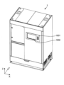
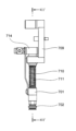
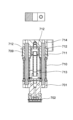
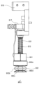
以下、返品薬を仕分けして格納する返品薬剤供給装置1を例として、本発明の一実施形
態を説明する。図1から図6は、本発明の実施形態に係る返品薬剤供給装置(薬剤仕分装
置)1を示す。返品薬剤供給装置1は、受入部100、昇降部200、認識部300、非
格納薬剤配置部400、格納部500、及び払出部600を備える。また、返品薬剤供給
装置1は、直交型ロボット700、スカラー型ロボット800、及びサポートトレー90
0(移送用容器)を備える。さらに、返品薬剤供給装置1は、図1に模式的に示す制御装
置1000を備える。制御装置1000は、図4に図示する制御盤1001(ディスプレ
イ1002を備える)からの入力、センサやカメラからの入力等に基づいて、返品薬剤供
給装置1の動作を統括的に制御する。
(Apparatus overview)
Hereinafter, one embodiment of the present invention will be described by taking as an example a returned-goods
0 (transport container). Furthermore, the returned-goods
返品薬剤供給装置1の主な機能の概要は、以下の通りである。返品薬剤供給装置1は、
例えばアンプル2A、バイアル2B、樹脂アンプル2Cである返品薬剤2(図8参照)の
形状、大きさ(長さL1と直径ないし幅W)、種類、使用期限のような性状を認識する。
本実施形態では、返品薬剤2には、種類、使用期限等に関する情報を含む文字情報やバー
コードが印刷されたラベル3が貼り付けられている。返品薬剤供給装置1は、ラベル3に
表示されたこれらの情報を読み取る。また、返品薬剤供給装置1は、認識後の返品薬剤2
をその返品薬剤2の識別情報(1個1個の返品薬剤2に付与されたユニークな情報)と関
連付けて一時的に格納し、処方データ(例えば電子カルテシステムである上位のシステム
(HIS: Hospital Information System)から受信する。)に基づいて、払い出しを行う。
格納時には、格納される返品薬剤2の大きさに応じて格納領域が設定される。返品薬剤2
の格納は、設定された格納領域に配置され、かつ払出時に個別の返品薬剤2を取出可能と
なる態様で行われる。さらに、返品薬剤供給装置1は、使用期限が過ぎている返品薬剤2
を排出する。
An overview of the main functions of the returned-goods
For example, the shape, size (length L1 and diameter or width W), type, expiration date, etc. of the returned drug 2 (see FIG. 8), which are
In this embodiment, the returned
is temporarily stored in association with the identification information of the returned medicine 2 (unique information given to each returned medicine 2), and prescription data (e.g., upper system (HIS: Hospital Payment is made based on the information received from the Information System).
At the time of storage, the storage area is set according to the size of the returned
is stored in a set storage area, and is performed in such a manner that individual returned
to discharge.
なお、本明細書で言う「薬剤」は、図8に示すように容器に収容された薬品を意味する
。したがって、「薬剤の形状及び大きさ」は、容器の形状及び大きさを意味し、「薬剤の
種類、使用期限などの情報」は、容器に収容された薬品の種類、使用期限などの情報を意
味する。また、実際には、「使用期限」の用語に代わって、「有効期限」の用語が使用さ
れる場合がある。ただ、これらの用語は実質的には同義である。そこで、本明細書では、
混乱を回避するために、「有効期限」を用いずに、「使用期限」のみを使用する。
The term "drug" as used herein means a drug contained in a container as shown in FIG. Therefore, "the shape and size of the drug" means the shape and size of the container, and "information such as the type and expiration date of the drug" refers to information such as the type and expiration date of the drug contained in the container. means. Also, in practice, the term “expiration date” may be used instead of the term “use date”. However, these terms are substantially synonymous. Therefore, in this specification,
To avoid confusion, do not use "expiration date", just "use by".
(受入部)
図1から図3に示すように、受入部100は、返品薬剤供給装置1を正面から見て左上
手前側に配置されている。
(Receiving department)
As shown in FIGS. 1 to 3, the receiving
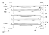
図7を併せて参照すると、受入部100は、水平方向(図においてX方向)に互いに対
向して配置された固定のラック部材101を備える。ラック部材101には、複数の返品
トレー(受入容器)4を多段配置された状態で保持するための、複数対のレール溝101
a,101aが設けられている。
Also referring to FIG. 7, the receiving
a, 101a are provided.
図8及び図9を参照すると、返品トレー4は、図において上方が開口したトレー本体4
aと、トレー本体4aの上端縁に設けられたフランジ状部4bとを備える。図8に示すよ
うに、返品トレー4に収容されている返品薬剤2(例えばアンプル2A、バイアル2B、
樹脂アンプル2C)は、形状、大きさ(長さL1と幅W)、種類、使用期限のような性状
が異なっている。また、返品トレー4に収容されている返品薬剤2の向きと姿勢は揃えら
れておらず、互いに異なる。つまり、返品トレー4に収容されている返品薬剤2は、非整
列状態である。ここで返品薬剤2の向きは、図においてXY平面において返品薬剤2の長
手方向(返品薬剤2の軸線A)が延びる方向をいう。返品薬剤2についての向きという用
語は、返品薬剤2の軸線Aが延びる向きに加え、返品薬剤2の先端2aと基端2bの向い
ている方向を含む場合がある。ただし、返品トレー4に収容されている返品薬剤2の形状
、大きさ、種類、使用期限のような性状が統一されていてもよい。また、返品トレー4に
収容されている返品薬剤2の向き及び姿勢が揃えられていてもよい。返品トレー4中の返
品薬剤2は、互いに部分的に重なり合っていてもよい。
Referring to FIGS. 8 and 9, the
and a flange-
The
図7に示すように、ラック部材101に設けられたレール溝101a,101aにより
、返品トレー4のフランジ状部4bが支持されている。レール溝101a,101aは、
ラック部材101の図においてY方向手前側の端面から奥側の端面まで貫通するように設
けられている。そのため、医療従業者のような作業者は、返品薬剤供給装置1の正面側か
ら、返品トレー4をレール溝101a,101aに対して出し入れできる。また、後述す
る昇降部200は、返品薬剤供給装置1の背面側から返品トレー4をレール溝101a,
101aに対して出し入れできる。
As shown in FIG. 7, the
In the drawing of the
101a.
受入部100は、図7において右側のラック部材101に設けられた動作準備ボタン1
02を備える。動作準備ボタン102は、収納する返品トレー4に対して1つずつ設けら
れている。作業者が返品トレー4を受入部100に収納後、対応する動作準備ボタン10
2を押下することで、制御装置1000により昇降部200は、押下された動作準備ボタ
ン102に対応する返品トレー4を引き出すことができる状態となる。即ち、作業者が返
品トレー4を受入部100に収納した場合でも、動作準備ボタン102が押下されない限
り、昇降部200は対応する返品トレー4を受入部100から移送しない。これに代えて
、返品トレー4が受入部100に収納されたことを自動的に検知するためのセンサを設置
してもよい。このセンサは、例えば重量センサであってもよい。これにより、制御装置1
000は、このセンサの出力に基づいて、昇降部200に返品トレー4を引き出す動作を
開始させることができる。
Receiving
02. One
2, the
000 can cause the
(昇降部)
図1から図3に示すように、昇降部200は、返品薬剤供給装置1を正面から見て左奥
に配置されている。
(lifting part)
As shown in FIGS. 1 to 3, the
図10を併せて参照すると、昇降部200は、Z方向に延びる固定の直動ガイド201
と、直動ガイド201に沿って昇降するキャリッジ202と、キャリッジ202に搭載さ
れたテーブル203を備える。テーブル203は底部203aと、底部203aに左右に
設けられた側部203b,203bと、底部203aの奥側(Y方向の奥側)に設けられ
た端部203cとを備える。テーブル203は手前側(Y方向の手前側)が開放している
。側部203b,203bには、レール溝204,204が設けられている。レール溝2
04,204により、返品トレー4のフランジ状部4bが支持され、それによってテーブ
ル203に返品トレー4が保持される。
Also referring to FIG. 10, the
, a
04 and 204 support the flange-
引き続き図10を参照すると、底部203aには返品薬剤供給装置1の奥行方向(Y方
向)に延びる固定の直動ガイド205が設けられている。また、この直動ガイド205に
沿って水平移動するキャリッジ206に、フック207の基端側が固定されている。
Continuing with FIG. 10, a fixed direct-acting
昇降部200は、受入部100から1個の返品トレー4を取り出して、後述する認識部
300と同様の高さ位置(図1において符号Hで概念的に示す)まで降下させることがで
きる(返品トレー取出動作)。また、昇降部200は、認識部300と同様の高さ位置H
から返品トレー4を受入部100に戻すことができる(返品トレー戻し動作)。
The elevating
return
返品トレー取出動作について説明すると、まず、テーブル203(キャリッジ202)
が、取り出し対象の返品トレー4が保持されている受入部100のレール溝101a,1
01aよりも少し低い位置まで上昇する。次に、フック207(キャリッジ206)が、
テーブル203の端部203c側から前進移動(Y方向手前側へ移動)する。続いて、テ
ーブル203が少し上昇し、その結果、返品トレー4のフランジ状部4b(図において奥
側の部分)とトレー本体4aとの間の隙間に、フック207が進入する。その後、フック
207が、テーブル203の端部203cへ後退移動(Y方向奥側へ移動)する。このフ
ック207の後退移動により、フランジ状部4bがレール溝204に引き込まれ、返品ト
レー4が受入部100からテーブル203に移載される。最後に、テーブル203(キャ
リッジ202)が符号H(図1)で示す位置まで降下する。
First, the table 203 (carriage 202)
However, the
It rises to a position slightly lower than 01a. Next, the hook 207 (carriage 206)
It moves forward from the
返品トレー戻し動作について説明すると、まず、テーブル203(キャリッジ202)
が符号Hで示す高さ位置から、返品トレー4を戻すレール溝101a,101a(返品ト
レー4を保持していない)に対応する高さまで上昇する。次に、その後、フック207(
キャリッジ206)が、テーブル203の端部203c側から前進移動(Y方向手前側へ
移動)する。その結果、フック207によって押された返品トレー4のフランジ状部4b
は、レール溝204,204から抜け出て、受入部100のレール溝101a,101a
に進入する。その後、テーブル203が少し降下し、それによってフック207は返品ト
レー4のフランジ状部4b(図において奥側の部分)とトレー本体4aとの間の隙間から
下方に抜け出る。最後に、フック207が、テーブル203の端部203c側に後退移動
する。
To explain the returned goods tray return operation, first, the table 203 (carriage 202)
rises from the height indicated by symbol H to a height corresponding to the
The carriage 206) advances from the
escapes from the
enter the After that, the table 203 is lowered slightly, whereby the
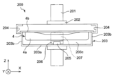
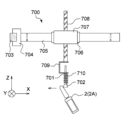
(直交型ロボット)
図11から図12Dを参照すると、直交型ロボット700(第1吸着部)は、図示しな
い真空源から吸込管713(図12A~図12D)を通じて供給される真空により返品薬
剤2を解放可能に吸着する吸着ノズル701を備える。吸着ノズル701の先端には、ゴ
ム製の吸着パッド702が取り付けられている。図1から図3を併せて参照すると、吸着
ノズル701が返品薬剤2を吸着保持し、又は吸着保持した返品薬剤2を吸着解除により
離すことができる範囲が、昇降部200(前述の高さ位置Hにあるときの返品トレー4)
の全範囲と、認識部300及び非格納薬剤配置部400を含むように、直交型ロボット7
00は構成されている。
(orthogonal robot)
11 to 12D, the orthogonal robot 700 (first adsorption unit) releasably adsorbs the returned
, the
00 is configured.
直交型ロボット700(吸着ノズル701)は、昇降部200のテーブル203(高さ
位置H)に保持された返品トレー4から返品薬剤2を吸着保持して取り出し、認識部30
0が備える後述の仮置き部(第1認識部)301に移送できる。また、直交型ロボット7
00は仮置き部301から返品薬剤2を吸着保持して取り出し、認識部300が備える後
述のラベル読取部(第2認識部)302に移送できる。さらに、直交型ロボット700は
、ラベル読取部302から返品薬剤2を吸着保持して取り出し、非格納薬剤配置部400
に移送できる。
The orthogonal robot 700 (suction nozzle 701 ) sucks and holds the returned
0 can be transferred to a temporary placement unit (first recognition unit) 301, which will be described later. In addition, the
00 can suck and hold the returned
can be transferred to
直交型ロボット700は、受入部100よりも下方側で返品薬剤供給装置1の奥行き方
向(Y方向)に延びる固定のY軸ビーム703と、このY軸ビーム703に沿って移動す
るキャリッジ704とを備える。キャリッジ704には、返品薬剤供給装置1の幅方向(
X方向)に延びるX軸ビーム705が固定されている。また、X軸ビーム705上を移動
するキャリッジ706が設けられ、このキャリッジ706にヘッド707が搭載されてい
る。ヘッド707にはボール螺子機構により昇降する昇降ロッド708が設けられている
。昇降ロッド708がZ軸周りに回転することにより、吸着ノズル701もZ軸周りに回
転できる。
The
An
図12A~Dを参照すると、ブラケット709と吸着ノズル701の間には、2つのば
ね710が介装されており、各ばね710の中心には、軸棒711がそれぞれ配置されて
いる。ブラケット709には下端に3つの貫通孔712が並んで設けられている。2つの
軸棒711は3つの貫通孔712のうち両端にある2つの貫通孔712を貫通し、ブラケ
ット709に対して摺動可能に配置されている。吸込管713は、中心の貫通孔712を
貫通し、軸棒711と同様にブラケット709に対して摺動可能に配置されている。この
3つの貫通孔712の上方には、抜止プレート714が配置されている。2つの軸棒71
1は、下端を吸着ノズル701に、上端を抜止プレート714に固定されている。これに
より、吸着ノズル701は、ブラケット709に対して弾性的に上昇可能である。
12A to 12D, two
1 has its lower end fixed to the
吸込管713の末端側(図において下側)は、吸着ノズル701を貫通して延び、吸着
パッド702内で開口し、基端側(図において上側)は図示しない真空源と連通している
。従って、吸着パッド702の下方にある物体を吸引(吸着)できる。また、直交型ロボ
ット700は、吸着ノズル701内の圧力を測定する圧力センサ(図示せず)が設けられ
ている。また、キャリッジ706には、ブラケット709に対する吸着ノズル701の相
対的な高さ位置(Z方向の位置)を検出するための位置センサ(図示せず)が搭載されて
いる。
The terminal side (lower side in the figure) of the
吸着ノズル701に吸着保持された返品薬剤2は、キャリッジ706の直動によりX方
向に移動し、キャリッジ704の直動によりY方向に移動し、昇降ロッド708の昇降に
よりZ方向に移動する。また、吸着ノズル701に吸着保持された返品薬剤2は、昇降ロ
ッド708のZ軸周りの回転により、吸着ノズル701の軸線(Z軸)回りに回転する。
Returned
(認識部と非格納薬剤配置部)
図1から図3を参照すると、認識部300は、照明303とカメラ304(第1撮影部
)を備える。照明303とカメラ304は、昇降部200の上方に位置している。また、
認識部300は、カメラ304と共に本発明における第1認識部の一例を構成する仮置き
部301とラベル読取部(本発明における第2認識部の一例)302を備える。仮置き部
301とラベル読取部302(ラベル読取装置)は、返品薬剤供給装置1を正面から見て
左下手前側に配置され、受入部100の下方に位置している。
(Recognition unit and non-stored drug placement unit)
Referring to FIGS. 1 to 3,
The
図13を併せて参照すると、仮置き部301は、返品薬剤2が載置される半透明板30
5(薬剤載置板)と、この半透明板305の下側に配置された照明306と、半透明板3
05の上方に位置するカメラ307(第2撮影部)を備える。
Also referring to FIG. 13 , the
5 (drug placement plate),
05 is provided with a camera 307 (second imaging unit).
図14を併せて参照すると、ラベル読取部302は、回転駆動される無端ベルト308
と、この無端ベルト308上に配置されたローラ309とを備える。返品薬剤2は、無端
ベルト308とローラ309が回転することで、それ自体の長手方向の軸線A回りに回転
する。また、ラベル読取部302は照明310と図1にのみ図示するカメラ311(本発
明における第3撮影部の一例)を備える。さらに、ラベル読取部302はバーコードリー
ダ(第1バーコードリーダ)312を備える。
Also referring to FIG. 14, the
and
図13を参照すると、非格納薬剤配置部400は、詳細は後述するが返品薬剤供給装置
1において取り扱い対象外の返品薬剤2、すなわち格納部500に原則的には格納しない
返品薬剤2(非格納薬剤2’)を格納する薬剤配置部であって、仮置き部301に隣接し
配置された2個の非格納薬剤配置箱401,402を備える。これらの非格納薬剤配置箱
401,402は、後述する格納トレー(格納容器)5の配置溝と同様の非格納薬剤2’
を保持するための配置溝を備える。
Referring to FIG. 13 , the non-stored
with a groove for holding the
(返品薬剤の認識完了までの動作)
ここで、受入部100の返品トレー4に収容された返品薬剤2に対する、向き及び姿勢
と、種類、形状、大きさ、使用期限等の性状との認識が完了するまでの、返品薬剤供給装
置1の動作を説明する。
(Operation until completion of recognition of returned medicine)
Here, the returned-goods
まず、受入部100から昇降部200のテーブル203に返品トレー4が移載される。
返品トレー4の移載後、テーブル203は、高さ位置H(図1参照)まで降下する。テー
ブル203が高さ位置Hまで降下した後に、認識部300による認識が開始される。まず
、照明303からテーブル203上の返品トレー4に対して上方から照明光(指向性の高
い光であることが好ましい)を照射しつつ、カメラ304による撮影を行う。そして、カ
メラ304で撮影した画像に基づいて、返品トレー4中の返品薬剤2の位置等が認識され
て格納対象薬品とする。この認識処理の詳細に関しては後述する。この認識結果に基づい
て、直交型ロボット700の吸着ノズル701が返品トレー4中の返品薬剤2を1個ずつ
吸着保持し、仮置き部301の半透明板305上に移載する(図13参照)。この際、吸
着ノズル701は、それ自体の軸線(Z軸)回りの回転により、吸着保持した返品薬剤2
の向きを調節する。
First, the
After the
direction.
仮置き部301では、返品薬剤2は、半透明板305上に載置される。照明306によ
り半透明板305の下方に配置された照明306が半透明板305に向かって光を照射す
る。照明光は高輝度の光であることが好ましい。照明306が光を照射しつつ、カメラ3
07が半透明板305上の返品薬剤2を撮影する。カメラ307によって撮影された画像
により、詳細は後述するが、返品薬剤2の形状、大きさ、及び向き(XY平面において軸
線Aが延びる方向であって先端2aと基端2bが向いている方向も含む)が認識される。
また、カメラ307によって撮影された画像により、返品薬剤2の吸着位置(直交型ロボ
ット700の吸着ノズル701とスカラー型ロボット800の吸着ノズル801で吸着さ
れる位置)が算出される。返品薬剤2の吸着位置の算出は後に詳述する。カメラ307で
撮影された画像による認識結果に基づいて、直交型ロボット700の吸着ノズル701が
半透明板305上の返品薬剤2を吸着保持し、ラベル読取部302に移載する。この際、
吸着ノズル701は、それ自体の軸線(Z軸)回りに回転により、吸着保持した返品薬剤
2の向きを調節する。
In the
07 photographs the returned
Also, based on the image captured by the
The
ラベル読取部302では、詳細は後述するが、無端ベルト308とローラ309の回転
により、返品薬剤2がそれ自体の軸線A(図14参照)回りに回転する。この回転する返
品薬剤2に対し、照明310から照明光を照射しつつ、ラベル読取装置(カメラ311及
びバーコードリーダ312)がその返品薬剤2のラベル3を読み取る。カメラ311が撮
影した画像により、返品薬剤2のラベル3に表示された使用期限等に関する文字情報が認
識されると共に、軸線A回りの返品薬剤2の姿勢が認識される。また、カメラ311によ
る撮影に加え、バーコードリーダ312によって、ラベル3に含まれるバーコードが読み
取られる。カメラ311が撮影した画像とバーコードリーダ312により読み取られたバ
ーコードにより、返品薬剤2の種類と使用期限が認識される。薬剤の種類及び使用期限の
認識は、カメラ311が撮像した画像とバーコードリーダ312によるバーコードの読み
取りのいずれか一方のみで行っても良い。例えば、返品薬剤2のラベル3に含まれるバー
コードに返品薬剤2の種類と使用期限が含まれている場合、カメラ311を設けずにバー
コードリーダ312のみを設け、バーコードリーダ312によるバーコードの読み取りに
よって、返品薬剤2の種類と使用期限を認識できる。認識終了後、ラベル3が上向き(Z
方向向き)となる姿勢で返品薬剤2の軸線A回りの回転が停止するように、無端ベルト3
08とローラ309の回転が停止する。ラベル3が上向きであるか否かは、カメラ311
の撮影画像に基づいて確認することができる。なお、後述のスカラー型ロボット800の
吸着ノズル801が吸着不可能な領域が返品薬剤2に存在する場合(例えば、図29に示
す樹脂アンプル2Cの側面のようにバリが存在する領域や吸着するとラベルがはがれうる
領域が返品薬剤2に存在する場合)、その領域が上向きにならないように返品薬剤2の回
転が停止されるのが好ましい。そのために、その吸着不可能領域が、薬剤に関連付けされ
て、後述する薬剤マスタに予め登録されている(予め記憶されている)。
In the
direction) so that the returned
08 and
can be confirmed based on the captured image. It should be noted that when there is an area in the returned
ラベル読取部302では、一対のローラではなく、無端ベルト308とローラ309の
回転により、返品薬剤2を軸線A回りに回転させる。無端ベルト308とローラ309の
組み合わせは、一対のローラと比較して、回転させることができる返品薬剤2の形状、大
きさ、及び種類の範囲が広い。
In the
仮に、ラベル読取部302が一対のローラによって返品薬剤2を回転させる構成である
場合、一対のローラの回転軸間の相対的な傾きないしはずれに起因して、返品薬剤2は一
対のローラの回転軸に沿った2つの方向のいずれかに移動することがある。かかる返品薬
剤2の移動方向を一方向に限定するには、一対のローラの回転軸間の相対的な傾きないし
はずれを厳密に調整する必要がある。また、この場合、返品薬剤2が一対のローラに対し
て傾いた姿勢で供給されることに起因して、返品薬剤2は一対のローラの回転軸に沿った
2つの方向のいずれかに移動することもある。
If the
これに対して、本実施形態では、図14に最も明瞭に示すように、無端ベルト308の
進行方向Fに対して、ローラ309の回転中心線Rcが傾斜している(すなわち進行方向
Fと回転中心線Rcの延在方向とが非直交に交差している)。かかる無端ベルト308と
ローラ309の配置により、返品薬剤2が無端ベルト308の幅方向に移動する方向を一
方向(図14において下向き)に制限できる。その結果、ラベル読取部302における返
品薬剤2の位置を揃えることができる。また、無端ベルト308の進行方向Fは、その上
に載置された返品薬剤2がローラ309に接近する方向である。一方、ローラ309の回
転方向は、無端ベルト308との対向領域において、無端ベルト308の進行方向FのX
方向成分に対して周速が逆方向になるような回転方向である。その結果、無端ベルト30
8とローラ309との間への返品薬剤2の噛み込み、特に径の小さい返品薬剤2の噛み込
みを抑制することができる。それに加えて、ラベル3が部分的に剥離している返品薬剤2
の場合には、その部分的に剥離したラベル3の部分の噛み込みを抑制することができる。
また、回転状態の無端ベルト308及びローラ309に当接することによって返品薬剤2
が位置決めされつつ一定の回転速度で回転するため、バーコードリーダ312は安定した
精度でその返品薬剤2のバーコードを読み取ることができる。
On the other hand, in this embodiment, as shown most clearly in FIG. intersects non-orthogonally with the extending direction of the center line Rc). By arranging the
The rotation direction is such that the peripheral speed is in the opposite direction to the direction component. As a result, endless belt 30
8 and the
In the case of (2), the part of the partially peeled
In addition, the returned
is positioned and rotates at a constant rotational speed, the
例えば、ラベル読取部302で認識された使用期限が既に経過している場合、あるいは
ラベル読取部302で使用期限が認識できなった場合、その返品薬剤2は、非格納薬剤2
’として、直交型ロボット700の吸着ノズル701により吸着保持されて、非格納薬剤
配置部400の非格納薬剤配置箱401,402に移載される。また、受入部100の返
品トレー4のうちいずれか(例えば最下段の返品トレー4)を、非格納薬剤配置部400
の一部として機能する非格納薬剤2’用のトレーとし、その非格納薬剤用返品トレー4に
非格納薬剤配置箱401,402の非格納薬剤2’が戻される。
For example, when the expiration date recognized by the
', is sucked and held by the
, and the non-stored medicines 2' in the non-stored
(スカラー型ロボットとサポートトレー)
図15及び図16、及び図17A~17Dを参照すると、スカラー型ロボット800(
第2ピッキング部)は、図示しない真空源から中央吸込管813及び側方吸込管814を
通じて供給される真空により返品薬剤2を解放可能に吸着する吸着ノズル801を備える
。吸着ノズル801の先端には、ゴム製の吸着パッド802(第1吸着パッド)が取り付
けられている。吸着ノズル801が返品薬剤2を吸着保持し、又は吸着保持した返品薬剤
2を吸着解除により離すことができる範囲が、認識部300のラベル読取部302と、格
納部500が備えるすべての格納トレー5の全範囲と、後述する払出位置に配置された払
出トレー8の全領域を含むように、スカラー型ロボット800は構成されている。
(Scalar type robot and support tray)
15 and 16, and 17A-17D, a scalar robot 800 (
The second picking unit) includes a
スカラー型ロボット800(吸着ノズル801)は、認識部300のラベル読取部30
2から返品薬剤2を吸着保持して取り出し、格納部500が備える後述の格納トレー5に
移送できる。また、スカラー型ロボット800は、格納トレー5から返品薬剤2を吸着保
持して取り出し、払出部600の後述する払出トレー8に移送できる。
The scalar robot 800 (suction nozzle 801 ) is the label reading unit 30 of the
2, the returned
図1から図3を併せて参照すると、スカラー型ロボット800は、返品薬剤供給装置1
の高さ方向(Z方向)に延びる一対の固定の直動ガイド803,803と、これら直動ガ
イド803,803上を移動するキャリッジ804,804を備える。キャリッジ804
,804によって、返品薬剤供給装置1の幅方向(X方向)に延びるX軸ビーム805の
端部が支持されている。X軸ビーム805にベース806が固定されている。ベース80
6に連結された第1アーム807の基端側がZ軸回りに回動し、第1アーム807の先端
側に連結された第2アーム808の基端側もZ軸回りに回動する。第2アーム808の先
端側にヘッド809がZ軸回りに回動可能に取り付けられている。ヘッド809に固定さ
れたブラケット810に、吸着ノズル801が保持されている。ヘッド809には、図1
5にのみ図示するバーコードリーダ812(第2バーコードリーダ)と返品薬剤2を検知
する有無検知センサ820とが搭載されている。バーコードリーダ812は、吸着ノズル
801に対して、側方にずれた位置に搭載されており、吸着ノズル801の下方に位置す
る返品薬剤2に貼付されたラベル3のバーコードを斜め上方から読み取るようになってい
る。言い換えれば、バーコードリーダ812は、ラベル読取部302における返品薬剤2
に対するバーコードリーダ312との位置関係と同様に、吸着ノズル801が対象の返品
薬剤2の上方に位置するときに、返品薬剤2に貼付されたラベル3のバーコードに対向す
るように配置されている。
Referring also to FIGS. 1 to 3, the
A pair of fixed linear motion guides 803, 803 extending in the height direction (Z direction) of , and
, 804 support the ends of an
6 rotates around the Z-axis, and the proximal end of a
5 and a presence/
Similar to the positional relationship with the
有無検知センサ820は、本実施形態では、反射型の光電センサであって、吸着ノズル
801の下方領域に向けて光を発行して、その反射光を受光することで、吸着ノズル80
1の下方領域における返品薬剤2の有無を検知するものである。
In this embodiment, the presence/
The presence or absence of the returned
吸着ノズル801に吸着保持された返品薬剤2は、X軸ビーム805(キャリッジ80
4)の直動によりZ方向に移動し、第1アーム807と第2アーム808の回動によりX
Y平面上を移動する。また、吸着ノズル801に吸着された返品薬剤2は、第2アーム8
08の先端部に対するヘッド809の回転により吸着ノズル801の軸線(Z軸)回りに
回動する。
Returned
4) moves in the Z direction, and the rotation of the
Move on the Y plane. Also, the returned
08 rotates around the axis (Z-axis) of the
図17A~17Dに示されるように、ブラケット810と吸着ノズル801との間には
、2つのばね811,811が介装されており、各ばね811の中心には、軸棒815が
それぞれ配置されている。ブラケット810には、下端に3つの貫通孔816が並んで設
けられている。2つの軸棒815は、3つの貫通孔816のうち、両端にある2つの貫通
孔816を貫通し、ブラケット810に対して摺動可能に配置されている。中央吸込管8
13は、中心の貫通孔816を貫通し、軸棒815と同様にブラケット810に対して摺
動可能に配置されている。この3つの貫通孔816の上方には抜止プレート817が配置
されている。2つの軸棒815,815は、下端を吸着ノズル801に、上端を抜止プレ
ート817に固定されている。これにより、吸着ノズル801は、ばね811により下向
きに付勢されつつ、ブラケット810に対して弾性的に上昇可能である。
As shown in FIGS. 17A to 17D, two
13 passes through a central through
中央吸込管813は吸着ノズル801を貫通して延び、吸着パッド802内において、
その末端側(図において下側)には小型吸着パッド818(第2吸着パッド)が設けられ
ている。中央吸込管813の基端側(図において上側)は図示しない真空源と連通してい
る。吸着ノズル801には、側面に貫通孔821が設けられており、この貫通孔を通じて
側方吸込管814が接続されている。側方吸込管814の基端側(図において上側)は図
示しない真空源と連通している。吸着ノズル801内には、内部の圧力を測定する圧力セ
ンサ(図示せず)が設けられている。
The
A small suction pad 818 (second suction pad) is provided on the terminal side (lower side in the drawing). The base end side (upper side in the drawing) of the
図18A、図18Bに示すように、吸着パッド802は、中空状とされ、上部の取付部
802aと、下部の吸着部802cと、取付部802aと吸着部802cとを接続する蛇
腹部802bと、を有する。図17Cを併せて参照して、取付部802aは、厚肉とされ
、吸着ノズル801の下部に外嵌しており、内側が吸着ノズル801の貫通孔816を介
して側方吸込管814に連通している。蛇腹部802bは、側方吸込管814から空気が
吸引されることで、上方に収縮されるようになっている。蛇腹部802bと吸着部802
cとの接合部802dの肉厚は、他の部分よりも薄肉とされ、これにより該接合部802
dから変形させやすくなっている。この結果、吸着時において、接合部802dを最初に
変形させることで、吸着パッド802の形状を維持して良好に吸着できるようになってい
る。また吸着パッド802は、小型吸着パッド818よりも吸着面の面積が大きいので、
小型吸着パッド818に比して吸着力が強く、より重い、或いはより大きな返品薬剤2を
吸着して高速で移送できる。
As shown in FIGS. 18A and 18B, the
The thickness of the
It is easy to transform from d. As a result, by first deforming the
Compared to the
吸着部802cは、略楕円状の形態をなしており、中央部に側方吸込管814に連通す
る開口部802eを有している。吸着部802cの長手方向の円弧部802fには、部分
的に厚肉とされた厚肉部802gが形成されており、これにより、剛性が弱い長手方向の
円弧部802fを補強して、吸着時における円弧部802fの変形に起因する吸着面から
の空気漏れを防止できる。また、円弧部802fの吸着面側には、突起802hが一体に
形成されている。突起802hは、吸着時において吸着不良とならない程度の微少な空気
漏れを許容する高さに形成されており、この結果、吸着時における吸着性を維持しつつも
、吸着解除時において突起802hからの空気漏れにより速やかに吸着を解除できる。
The
また、図19A、図19Bを参照すると、吸着部802cは下面視で略楕円状であるの
で、吸着部802cを長方形で形成した場合(図19A、図19Bに破線で示す)に比し
て、小型吸着パッド818によって返品薬剤2を吸着保持した場合の、返品薬剤2の胴部
への吸着部802cの巻き込み量を低減できる。これにより、返品薬剤2を格納トレー5
Aの配置溝7上で吸着を解除して退避するときに、前記巻き込みにより返品薬剤2を回転
し又は移動させてしまうことを防止できる。
Also, referring to FIGS. 19A and 19B, since the
It is possible to prevent the returned
図18A、図18Bを参照すると、小型吸着パッド818は、中空状とされ、吸着パッ
ド802と中心軸心(Z軸方向)を略一致させて、吸着パッド802の内側に配置されて
おり、上部の取付部818aと、下部の吸着部818cと、取付部818aと吸着部81
8cとを接続する蛇腹部818bと、を有する。取付部818aは、中央吸込管813の
下部に、連通可能に取り付けられている。蛇腹部818bは、中央吸込管813から空気
が吸引されることで、上方に収縮されるようになっている。吸着部818cは、略円形状
をなしており、中央部に中央吸込管813に連通する開口部818dを有している。吸着
部818cは、略円形状であるので、円筒状の返品薬剤の筒部に追従しやすく、空気漏れ
が生じにくく、良好に吸着できる。
18A and 18B, the
and a
また、図17Cに実線で示すように、吸着ノズル801が吸着状態にないとき、吸着パ
ッド802の下端部が、小型吸着パッド818の下端部よりも下方に位置している。一方
、図17Cに破線で示すように、吸着ノズル801が吸着状態(中央吸込管813、側方
吸込管814の両方を通じて吸引する)のとき、小型吸着パッド818’の下端部が、吸
着パッド802’の下端部よりも下方に位置している。これにより、吸着状態において、
吸着パッド802によって小型吸着パッド818による吸着が遮られることなく、小型吸
着パッド818によって良好に吸着できる。
17C, the lower end of the
The adsorption by the
本実施形態では、制御装置1000は、カメラ307で撮影された画像により検出され
又はラベル読取部302で認識された、返品薬剤2の形状、大きさ、種類等に応じて、返
品薬剤2を吸着するための最適な吸着パッドを設定する。例えば、返品薬剤2の胴部の直
径が28mm以上の場合、中央吸込管813及び側方吸込管814の両方を使用して吸引
し、小型吸着パッド818及び吸着パッド802の両方によって吸着を行う。返品薬剤2
の直径が28mm未満の場合、中央吸込管813のみを使用して吸引し、すなわち小型吸
着パッド818のみによって吸着を行う。なお、小型吸着パッド818及び吸着パッド8
02の両方によって返品薬剤2を吸着し、その後、返品薬剤2をリリースするときは、先
に吸着パッド802の吸引を停止するのが好ましい。これにより、小型吸着パッド818
の形状の復帰を早めることができる(同時に吸引を停止する場合に比べて)。
In this embodiment, the
is less than 28 mm in diameter, only the
02 adsorb the returned-
shape recovery (compared to stopping suction at the same time).
返品薬剤2の直径が28mm以上の場合では、側方吸込管814のみを使用して吸引し
、すなわち吸着パッド802のみによって吸着を行ってもよい。また、返品薬剤2の胴部
に貼り付けられたラベル3を吸着すると、これが剥がれることがある。したがって、吸引
可能領域又は吸引不可能領域を予め設定し、これを防止してもよい。吸引可能領域又は吸
引不可能領域が狭小な場合、返品薬剤2の直径が28mm以上でも小型吸着パッド818
によって吸着してもよい。また、吸着パッド802のみで返品薬剤2を吸着した後、返品
薬剤2の吸着外れを検知した場合、吸着パッド802及び小型吸着パッド818の両方で
、当該吸着が外れた返品薬剤2を吸着するようにしてもよい。
If the returned
may be adsorbed by Further, when it is detected that the returned-
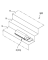
図1、図15、及び図16を参照すると、サポートトレー900は、スカラー型ロボッ
ト800のベース806に対して昇降するロッド901の下端に固定されている。本実施
形態では、サポートトレー900は後述する格納トレー5と同様の返品薬剤2を保持する
ための配置溝を備える。図16に示すように、ロッド901の昇降により、サポートトレ
ー900は、吸着ノズル801に吸着保持された返品薬剤2に接近する高さ位置と、吸着
ノズル801に吸着保持された返品薬剤2から離隔する高さ位置とに昇降移動する。
Referring to FIGS. 1, 15 and 16,
吸着ノズル801が返品薬剤2を吸着して移送するとき、スカラー型ロボット800は
、第1アーム807、第2アーム808により吸着ノズル801を水平方向に移動させて
、サポートトレー900の上方に位置させる。このとき、吸着された返品薬剤2がサポー
トトレー900の配置溝の向きに一致するように、ヘッド809が回動される。そして、
ロッド901を上昇させることで、サポートトレー900が、返品薬剤2から離隔する高
さ位置から、返品薬剤2に接近する高さ位置に移動される。これにより、移送中の返品薬
剤2が、吸着されている吸着パッド802及び/又は小型吸着パッド818から外れたと
しても、吸着ノズル801の下方に落下することを、サポートトレー900で防止するこ
とができる。これにより、吸着外れによる返品薬剤2の損傷を防止しつつ、より高速で返
品薬剤2を移送できる。
When the
By raising the
また、サポートトレー900に落下した返品薬剤2は、吸着ノズル801により再び吸
着されて、移送されてもよい。このとき、吸着ノズル801に設けた圧力センサ(図示し
ない)により、吸着が外れたことを検知してもよい。また、上述したように返品薬剤2は
、サポートトレー900上の配置溝に向きを一致させられて移送されるので、吸着ノズル
801による吸着が外れた場合、向き、姿勢が変わることなく、吸着ノズル801の直下
の配置溝に落下することになる。これにより、返品薬剤2が吸着ノズル801の直下にあ
ると予測することができるので、当該返品薬剤2を吸着ノズル801によって再吸着する
時の成功率を高めることができる。
Moreover, the returned-
なお、返品薬剤供給装置1が取り扱う返品薬剤2の大きさや形状によっては、返品薬剤
2を吸着パッド802が吸着保持したときに、図17Cに示すように縮んだ吸着パッド8
02の蛇腹部802bが取付部802aに接触することがある。この接触が繰り返される
ことにより、蛇腹部802bが破損する可能性がある。
Note that depending on the size and shape of the returned-
02 bellows
図20A及び20Bは、取付部と蛇腹部との接触を抑制することができる吸着パッド1
802が取り付けられた吸着ノズル801が示されている。図20A及び20Bに示すよ
うに、吸着パッド1802の取付部1802aには、蛇腹部1802bが縮んだときに該
蛇腹部1802bとの接触を回避するための逃げ部1802jが形成されている。具体的
には、取付部1802aと蛇腹部1802bとの間の接合部から斜め上方向に延在する傾
斜面として、逃げ部1802jは取付部1802aに形成されている。このような逃げ部
1802jを取付部1802aが備えることにより、取付部1802aと縮んだ蛇腹部1
802bとの接触を抑制することができる。
20A and 20B show a
A
Contact with 802b can be suppressed.
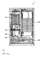
(格納部)
図1から図3に示すように、格納部500は、返品薬剤供給装置1を正面から見て右奥
に配置されている。
(storage unit)
As shown in FIGS. 1 to 3 , the
図21及び図22を併せて参照すると、格納部500はZ方向に延びる直動ガイド50
1を備える。この直動ガイド501には、格納トレー5(格納容器)を取り出し可能に保
持する保持枠502が昇降自在に保持されている。保持枠502は多段に重ねて配置され
ている。多段配置された格納トレー5の両側には、Z方向に延びる直動ガイド503,5
03が配置されている。これらの直動ガイド503,503上を昇降するキャリッジ50
4,504が設けられている。キャリッジ504には、図21に示す引込位置と図22に
示す突出位置とに移動可能なリフト機構505(間隔形成機構)が搭載されている。リフ
ト機構505は図において奥行方向にも配置されている。また、リフト機構505を多段
配置してもよい。
Referring to FIGS. 21 and 22 together, the
1. A holding
03 are arranged.
4,504 are provided. The
図21のようにリフト機構505が引込位置にある状態で、1個の保持枠502に対応
する位置にキャリッジ504,504が移動する。次に、リフト機構505が図22に示
すように突出位置に移動し、保持枠502の下側に進入する、この状態でキャリッジ50
4,504が上昇すると、リフト機構505が進入した保持枠502とそれよりも上段の
保持枠502とが上方に持ち上げられる。その結果、リフト機構505が進入した保持枠
502と、それよりも1段下側の保持枠502との間に、間隔Gが形成される。この間隔
Gを介してスカラー型ロボット800の吸着ノズル801は、リフト機構505が進入し
た保持枠502の1段下側の保持枠502に保持された格納トレー5へのアクセスが可能
となる。言い換えれば、この間隔Gが設けられることで、スカラー型ロボット800の吸
着ノズル801は、すべての格納トレー5に対して、返品薬剤2を格納トレー5に移載す
る動作(格納動作)と、返品薬剤2を吸着保持して格納トレー5から取り出す動作(払出
動作)とが可能である。
With the
4 and 504 rise, the holding
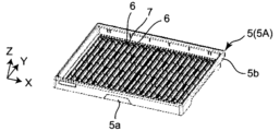
図23Aから図24Cを参照すると、格納トレー5には、比較的小型の返品薬剤2の格
納に適した格納トレー5A(Sサイズ)と、中型の返品薬剤2の格納に適した格納トレー
5B(Mサイズ)と、比較的大型の返品薬剤2の格納に適した格納トレー5C(Lサイズ
)とがある。格納部500は、これら3種類の格納トレー5A~5Cを少なくとも1個備
えている。個々の格納トレー5(5A~5C)は、図において上方が開口したトレー本体
5aと、トレー本体5aの上端縁に設けられたフランジ状部5bとを備える。
23A to 24C, the
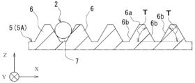
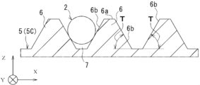
図25を併せて参照すると、トレー本体5aの底部には、返品薬剤供給装置1に奥行方
向(Y方向)に延び、返品薬剤供給装置1の幅方向(X方向)に間隔をあけて配置された
複数の突条(突部)6が設けられている。隣接する突条6間には、直線状の配置溝(凹部
)7が形成されており、この配置溝7に返品薬剤2が収容される。図24A~図24Cを
参照すれば明らかなように、3種類の格納トレー5A~5Cは、突条6の寸法(高さ及び
幅)とピッチが異なるため、配置溝7の寸法(深さと幅)が異なる。この配置溝7の寸法
の相違により、前述のように3種類の格納トレー5A~5Cは、格納するのに適した返品
薬剤2の寸法が異なる。
Referring also to FIG. 25 , at the bottom of the
突条6は、頂部6aと、頂部6aの両側縁部から下方に進むにつれて互いに離間する一
対の傾斜部6b,6bと、を有している。傾斜部6bは、比較的大きな勾配、すなわち急
斜面に設定されている。返品薬剤2が配置溝7に吸着ノズル801によって移送されると
きに、返品薬剤2の中心軸と配置溝7の中心位置とが一致していない場合がある。この場
合であっても、傾斜部6bが急斜面に設定されているので、返品薬剤2を傾斜部6bに沿
って下方へガイドさせやすく、返品薬剤2の回転が抑制される。すなわち、返品薬剤2を
、ラベル3が上方に位置する状態を維持したまま、格納トレー5に格納され、このときラ
ベル3のバーコードは斜め上方を指向する位置に維持されており、すなわち、バーコード
リーダ812と対向するように位置している。これにより、後述する払出作業において、
格納トレー5に格納された返品薬剤2の処方データとの照合を行えるようになっている。
なお、傾斜部6b水平方向に対する傾斜角度Tは、50°~80°の範囲に設定されてい
る。傾斜角度Tが50°よりも小さい場合、返品薬剤2は傾斜部6bとの接触により回転
する可能性がある。傾斜角度Tが80°よりも大きい場合、配置溝7で収容可能な返品薬
剤2の胴部径が制限されることになる。本実施形態では、傾斜角度Tは、好ましくは65
°に設定されている。傾斜角度を65°に設定することで、配置溝7で収容可能な返品薬
剤2の種類が制限されることなく、返品薬剤2の軸線A回りの回転を防止しながら収容で
きる。
The
The prescription data of the returned
The inclination angle T of the
° is set. By setting the inclination angle to 65°, the types of returned
さらに、格納トレー5の表面の粗度を低減させることで、返品薬剤2を傾斜部6bに対
して滑りやすくしてもよい。これにより、より一層、返品薬剤2の回転を抑制できる。ま
た、格納トレー5と保持枠502との間に制振ゴムを設けて、格納トレー5と保持枠50
2との間の相対変位及び振動を抑制してもよい。これにより、格納トレー5がリフト機構
505により上下動された場合でも、該上下動による振動が格納トレー5上の返品薬剤2
に伝達されることを抑制できる。制振ゴムは、格納トレー5及び保持枠502のいずれか
一方又は両方に貼り付けてもよい。
Furthermore, by reducing the roughness of the surface of the
2 may be suppressed relative displacement and vibration. As a result, even if the
can be suppressed from being transmitted to The damping rubber may be attached to one or both of the
また、格納トレー5の、少なくとも、返品薬剤が格納される表面側(図中上方)は、黒
色とされている。これにより、格納トレー5上に返品薬剤2が存在していないにもかかわ
らず、反射型光電センサである有無検知センサ820から照射される光が格納トレー5で
反射されることによって、返品薬剤2の存在を誤検知することを防止している。また、格
納トレー5の裏面側(図中下方)に、スポンジ等の緩衝材を貼り付けてもよい。これによ
り、当該緩衝剤が貼り付けられた格納トレー5の下段側の格納トレー5に、緩衝材を押し
付けることで、下段側の格納トレー5上の返品薬剤2の回転、移動等の動きを規制して、
返品薬剤2のラベル面を上方に維持したまま、その位置を維持しやすい。
At least the surface side (upper side in the drawing) of the
It is easy to maintain the position while maintaining the label surface of the returned
(払出部)
払出部600は搬送機構601を備える。搬送機構601は、図1に模式的に示す入口
602から払出位置(格納部500の図において手前側の位置)まで払出トレー8を移動
させて位置決めし、払出作業完了後の払出トレー8を図1に模式的に示す出口603から
搬出する。
(Payment department)
The
(返品薬剤の格納と払出の動作)
認識部300における認識完了後の返品薬剤2を格納部500に格納する動作(格納運
転)と、格納部500から払出部600に払出位置に配置された払出トレー8に払い出す
動作(払出運転)とを説明する。格納動作及び払出動作は、制御装置1000(運転制御
部)によって、主に、認識部300、格納部500、払出部600、スカラー型ロボット
800を制御して動作させることで実行される。
(Operation of storage and dispensing of returned medicine)
An operation (storage operation) of storing the returned
まず、格納動作を説明する。 First, the storage operation will be explained.
ラベル読取部302の返品薬剤2は、スカラー型ロボット800の吸着ノズル801に
より吸着保持される。吸着ノズル801により吸着保持された返品薬剤2に対して、少な
くともその返品薬剤2の大きさに応じて、格納領域、すなわち格納時に占める範囲との格
納位置(どの格納トレー8のどの位置に格納されるか)が設定される。本実施形態では、
格納領域のうち格納時に占める範囲はその返品薬剤2の長さL1と幅Wに対応する。格納
時に示す領域は、他の返品薬剤2と干渉しないためのマージンを含む。格納部500の複
数の格納トレー5のうち、いずれの格納トレー5のいずれの配置溝7に吸着ノズル801
により吸着保持されている返品薬剤2を配置可能かが検索される。この検索結果に応じ、
返品薬剤2を配置する格納トレー5と配置溝7(返品薬剤2の格納位置)が決定される。
1個の格納トレー5に着目すると、図25に示すように「3番」の配置溝7が既に返品薬
剤2で埋まっている場合、それ以外の配置溝7が吸着ノズル801により吸着されている
返品薬剤2を配置する格納位置の候補となる。例えば、「6番」の溝の場合、2個の返品
薬剤2が既に配置されているが、これらの返品薬剤2間の長さが格納しようとしている返
品薬剤2について前述した格納時に示す範囲以上であれば、吸着ノズル801により吸着
保持されている返品薬剤2を配置する候補となり得る。
The returned
The area occupied during storage in the storage area corresponds to the length L1 and width W of the returned
It is searched whether or not the returned
The
Focusing on one
前述のように、ラベル読取部302での認識終了時には、返品薬剤2はラベル3が上向
きとなる姿勢である。スカラー型ロボット800の吸着ノズル801は、ラベル3のバー
コードが上向きの姿勢を維持したままで、返品薬剤2を吸着保持して該当する格納トレー
5の該当する配置溝7、つまり前述のように決定された格納領域に返品薬剤2を移載する
。
As described above, when the recognition by the
図21及び図22を参照して説明したように、格納部500はリフト機構505により
保持枠502間に間隔Gを設けることができるように構成されている。従って、返品薬剤
2を吸着保持したスカラー型ロボット800の吸着ノズル801は、多段配置された保持
枠502のいずれに保持された格納トレー5に対しても、自由にアクセスし、吸着保持し
ている返品薬剤2を載置できる。
As described with reference to FIGS. 21 and 22, the
また、図23A~図24Cを参照して説明したように、格納部500の格納トレー5に
は、サイズが異なる3種類の格納トレー5A~5Cが含まれている。従って、制御装置1
000は認識部300、格納部500、及びスカラー型ロボット800を制御することで
、格納する返品薬剤2の大きさによる制約を受けずに、形状、大きさ、種類等に応じて設
定される格納トレー5に、認識が終了した返品薬剤2を格納部500に収納できる。
Further, as described with reference to FIGS. 23A to 24C, the
000 controls the
格納部500に格納されている返品薬剤2に関し、制御装置1000は個々の返品薬剤
2の識別情報と関連付けて、前述の格納領域、つまりいずれの格納トレー5のいずれの位
置(配置溝7とのその配置溝7上での位置)に配置されているかを記憶している。また、
制御装置1000は、個々の返品薬剤2の識別情報と関連付けて、種類と使用期限を記憶
している。
Regarding the returned
The
次に、払出作業を説明する。 Next, the dispensing work will be explained.
スカラー型ロボット800の吸着ノズル801は、格納部500の格納トレー5から返
品薬剤2を吸着保持し、払出位置に配置された払出トレー8に移載する。
The
払出作業は、例えば電子カルテシステムである上位のシステムから返品薬剤供給装置1
が受信した処方データに基づいて実行される。前述のように、格納部500に格納された
返品薬剤2の種類及び使用期限と識別情報とが関連付けて記憶され、かつ個々の返品薬剤
供給装置1が格納部500のどこに配置されているかも識別情報と関連付けて記憶されて
いる。具体的には、制御装置1000は、格納部500に格納された返品薬剤2の種類、
使用期限、及び格納領域と、識別情報とを関連付けて記憶している薬品マスタを備える。
しかも、前述のように、多段配置された格納トレー5間に間隔Gを設けることできるので
、吸着ノズル801は、多段配置された格納トレー5のいずれに格納された返品薬剤2で
あっても、必要に応じて自由に吸着保持できる。従って、薬品マスタを参照した結果、処
方データに含まれる薬剤が格納部500に格納されている返品薬剤2であることが確認で
きれば、処方データに応じて制約なく払い出すことができる。また、同一種類の薬剤のう
ち使用期限が近いものから払い出す等、処方データに応じて効率的な払出が可能である。
さらに、薬品マスタを参照した結果、処方データに含まれる薬剤が格納部500に格納さ
れていないことを確認できれば、必要な表示を制御盤1001のディスプレイ1002に
表示する等の処理を実行できる。
Dispensing work is performed by sending the returned
is performed based on the received prescription data. As described above, the type and expiration date of the returned
A medicine master storing an expiration date, a storage area, and identification information in association with each other is provided.
In addition, as described above, since the space G can be provided between the
Furthermore, if it can be confirmed by referring to the drug master that the drug contained in the prescription data is not stored in the
払出作業の動作を、具体的に説明する。リフト機構505によって形成された間隔Gを
通して、スカラー型ロボット800の吸着ノズル801が、払出対象の返品薬剤(以下、
払出作業の説明において、払出薬剤と称する)2にアクセスする。このとき、バーコード
リーダ812により、当該払出薬剤2のラベルを検知して、制御装置1000は、払出対
象の払出薬剤2であるか否かを照合する。払出対象の払出薬剤2であることが確認される
と、吸着ノズル801により、当該払出薬剤2が吸着されて、格納トレー5から取り出さ
れて、払出トレー8に移送される。このとき、格納部500に払出対象の払出薬剤2が複
数存在している場合には、制御装置1000は、使用期限が最も早い払出薬剤2を払出対
象の払出薬剤2として決定し、当該払出薬剤2を払い出すように制御する。
The operation of the dispensing work will be specifically described. Through the gap G formed by the
In the description of the dispensed operation,
一方、制御装置1000により、当該払出薬剤2が払出対象の払出薬剤2ではないと判
断された場合、または、ラベル3(バーコード)が認識できなかった場合には、制御装置
1000は、吸着ノズル801で、当該払出薬剤2を吸着して、認識部300のラベル読
取部302に移送するように制御する。ラベル読取部302において、払出薬剤2のラベ
ル3が認識されれば、当該払出薬剤2は、スカラー型ロボット800によって、格納部5
00に再度格納される。一方、ラベル読取部302において、払出薬剤2のラベル3が認
識されなければ、当該払出薬剤2は、直交型ロボット700によって、非格納薬剤配置部
400(非格納薬剤配置箱401,402)に移送されることになる。或いは、払い出そ
うとしている払出薬剤2と合致した場合には、スカラー型ロボット800によって、その
まま払出トレー8に移送してもよい。
On the other hand, when the
00 again. On the other hand, if the
なお、制御装置1000は、払出動作を、格納動作に優先して行うように制御する。こ
れにより、速やかな払出を実現できる。また、複数の払出薬剤2を払い出す場合、1個ず
つ格納部500から払出部600に払出薬剤2を移送する他、サポートトレー900をバ
ッファとして使用することで、まとめて移送してもよい。すなわち、払出対象の複数の払
出薬剤2を格納部500からサポートトレー900に一時的に仮置きして、纏めてサポー
トトレー900から払出部600に移送させてもよい。これにより、格納部500と払出
部600との間をスカラー型ロボット800が、払出本数分、往復移動することがなくな
り、短時間で払出作業を行うことができる。また。払出部600に払出トレー8が不在の
ときにも、サポートトレー900をバッファとして使用することで、払出作業を停止させ
ることがないので、払出作業を効率的に行える。
Note that the
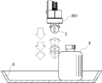
また、払出トレー8に既に大型のボトル等の薬剤が載置されているとき、スカラー型ロ
ボット800は、払出トレー8に減速して接近するように制御装置1000によって制御
される。制御装置1000は、払出トレー8に大型のボトル等の薬剤が載置されているこ
とを、薬剤有無検知センサ(図示しない)によって検知してもよいし、例えば電子カルテ
システムである上位のシステムから返品薬剤供給装置1が受信した処方データから検知し
てもよい。これにより、図26A及び図26Bに示すように、大型のボトル等の薬剤に緩
やかに接触させて、この接触のために吸着ノズル801から払出中の払出薬剤2が外れた
としても、該払出薬剤2を払出トレー8上に収容させることができる。言い換えれば、吸
着ノズル801を払出トレー8に減速させずに接近させた場合の、大型のボトル等と吸着
ノズル801に吸着保持された払出薬剤2との強接触によって、当該払出薬剤2が払出ト
レー8から飛び出すことを防止している。
Further, when medicine such as a large bottle is already placed on the dispensing
(スキャン動作)
次に、スキャン動作について述べる。スキャン動作とは、例えば、ユーザが格納トレー
5に直接にアクセスした場合に行われ、格納トレー5上に返品薬剤(又は払出薬剤)2が
ないことを確認するための動作である。ここで、ユーザが格納トレー5に直接にアクセス
する場合とは、処方データに基づく払出動作以外に、ユーザが手動で格納トレー5から返
品薬剤2を直接に取り出す場合を指し、例えば、返品薬剤2が破損していて、この返品薬
剤2を吸着ノズル801で吸着することができない場合や、使用期限を徒過した返品薬剤
2を取り出す場合や、格納トレー5から纏めて、複数の返品薬剤2を取り出す場合等が含
まれる。
(scan operation)
Next, the scanning operation will be described. The scanning operation is performed, for example, when the user directly accesses the
この場合、図4に示される外装パネルを開閉することで、対象の格納トレー5に直接に
アクセスできるようになる。このとき、対象の格納トレー5上の全ての返品薬剤2がユー
ザにより取り出されることを要する。なぜなら、対象の格納トレー5から一部の返品薬剤
2のみを取り除くようにした場合、ユーザによって直接にアクセスされたことで、取り除
かれなかった返品薬剤2の位置、ラベルの位置が変化しているおそれがあり、この場合、
以降の払出動作において、位置が変化した返品薬剤2をうまく吸着できないことがあるた
めである。すなわち、ユーザが直接に格納トレー5にアクセスする場合には、当該格納ト
レー5上の全ての返品薬剤2を取り除くように運用されており、スキャン動作とはユーザ
が直接にアクセスした格納トレー5から全ての返品薬剤2が取り除かれていることを確認
するために行われるものである。また、手動でアクセスされた格納トレー5は、スキャン
動作が完了して、当該格納トレー5上に返品薬剤2が無いことが確認されるまで、制御装
置1000は、当該格納トレー5に新たな返品薬剤2を格納しない。これにより、返品薬
剤2が残っているかもしれない不確かな格納トレー5に、新たな返品薬剤2を格納するこ
とを防止できる。
In this case, by opening and closing the exterior panel shown in FIG. 4, the
This is because the returned-
スキャン動作のとき、リフト機構505によって形成された間隔Gを通して、スカラー
型ロボット800の吸着ノズル801が、スキャン動作の対象とされる格納トレー5にア
クセスする。このとき、吸着ノズル801に設けられた有無検知センサ820から照射さ
れる光を格納トレー5上で走査させて、返品薬剤2があった場合に反射される光を有無検
知センサ820で受光することで、格納トレー5上の返品薬剤2の有無が検知される。な
お、上述したように格納トレー5の返品薬剤2が格納される面は黒色とされているので、
有無検知センサ820から照射される光が格納トレー5の表面から反射される反射光を受
光することによる、返品薬剤2の誤検知が防止されている。
During the scanning operation, the
The erroneous detection of the returned
また、スキャン動作は、対象の格納トレー5において、各配置溝7ごとに分割して行わ
れるようになっている。すなわち、図27に示されるように、格納トレー5上の全ての配
置溝7を纏めて一度に検知するのではなく、例えば1番の配置溝7をスキャン動作し、次
に払出動作又は格納動作をした後に、2番の配置溝7をスキャン動作するようになってい
る。言い換えれば、スキャン動作は、払出動作又は格納動作が行われないときに、実施さ
れるようになっており、これにより、払出動作及び格納動作を優先して行えるようになっ
ている。
Further, the scanning operation is divided for each
また、各配置溝におけるスキャン動作は、配置溝の延びる方向に沿って、ジグザグ状に
走査して行われる。具体的には、図27の1番の配置溝7における走査軌跡D1を示すよ
うに、有無検知センサ820は、返品薬剤2の幅に概ね対応してジグザグ状に配置溝7に
沿って走査するようになっている。例えば、走査軌跡D1は、配置溝7を横断する方向に
20mm進みつつ、配置溝の延びる方向に15mm進むように配置溝7の延びる方向に対
して傾斜して、各配置溝7をジグザグ状に走査する。これにより、例えば、格納トレー5
上に返品薬剤2が残っており、該返品薬剤2が反射光を検知することが難しい黒色であっ
て、且つ、ラベル3が上方に位置していない場合でも、ジグザグ状の走査軌跡D1によれ
ば、上方位置にないラベル3に光を照射させて、このラベル3からの反射光を受光するこ
とで、確実に格納トレー5に残った返品薬剤2を検知できる。
Further, the scanning operation in each placement groove is performed by scanning in a zigzag pattern along the direction in which the placement groove extends. Specifically, as shown by scanning locus D1 in No. 1
Even if the returned
すなわち、スキャン動作を配置溝7の延びる方向に沿って直線的に走査(図中の走査軌
跡D2)するのでは、黒色の返品薬剤2であって、そのラベルが上方からずれた位置にあ
る場合には、当該返品薬剤2を検知することができない。しかしながら、有無検知センサ
820をジグザグに走査させることで、仮に表示ラベルが上方に位置しておらず、側方に
ずれていたとしても、当該ずれた表示ラベルを検知することができるので、返品薬剤2が
黒色の場合であっても確実に返品薬剤2を有無検知できる。
That is, if the scanning operation is performed linearly along the direction in which the
以上のように、本実施形態の返品薬剤供給装置1によれば、種類、形状、大きさ、使用
期限等の性状が種々異なり、かつ非整列状態で供給された返品薬剤2を、自動的に認識し
て高い自由度を確保して格納でき、処方データに応じて自由に払い出すことができる。
As described above, according to the returned-goods
また、格納部500の各格納トレー5は、格納する際に水平に引き出すことを必要とし
ないので、格納トレー5を引き出すためのスペースを必要とせず、この結果、格納部50
0をコンパクトに構成できる。また、格納トレー5上において、返品薬剤2が格納される
格納領域と種類とを関連付けて格納されるので、各格納トレー5上に様々な返品薬剤2を
格納することができる。これにより、格納トレー5を各薬剤の種類に応じて準備する必要
がなくなり、必要とされる格納トレー5の個数の増大を抑制できる。例えば、無造作に返
品トレー4に収容された性状の異なる様々な返品薬剤2を、取出可能なように格納部50
0の各格納トレー5に格納できる。加えて、返品薬剤2以外の薬剤、例えば在庫として補
充される同じ性状の複数の薬剤をも、取出可能なように格納部500の各格納トレー5に
格納できる。また、本装置では、スカラー型ロボット800が格納トレー5から返品薬剤
2を出し入れし、そのため、格納トレー5に蓋も排出機構も必要としない。しかも、格納
トレー5を多段配置することで、上側の格納トレー5が下側の格納トレー5の蓋としての
機能を奏し、格納トレー5は、高さが返品薬剤2の径方向の高さに対応したコンパクトに
構成できる。したがって、格納部500をコンパクト化できる。
In addition, since each
0 can be configured compactly. Moreover, on the
0 can be stored in each
また、格納トレー5は、引き出されることがなく、格納トレー5に格納された返品薬剤
2に水平方向への力が作用しない。これにより、格納トレー5に格納された返品薬剤2の
向き、位置を格納時のまま、特にラベル3のバーコードをバーコードリーダに対向する斜
め上方位置に維持することができ、この結果、格納トレー5上における返品薬剤2の照合
を容易にして払い出しできる。さらに、処方情報に基づいて、払出作業を行う場合、払出
薬剤2のバーコードを照合して、間違いのない払出作業を実施できる。また、払出対象の
払出薬剤2のうち使用期限が最も早いものを払い出すので、効率的な払出作業を実施でき
る。これにより、作業者が薬種や使用期限等の薬剤管理に必要な情報を気にせずに格納で
きることを実現したものである。
Further, the
ここからは、本実施形態の返品薬剤供給装置1における返品薬剤供給装置1の認識部3
00における仮置き部301及びラベル読取部302ついて、さらに詳細に説明する。
From here, the
00, the
まず、認識部300においては、返品薬剤2の形状、大きさ、種類、及び使用期限(性
状)が認識される。具体的には、認識部300の仮置き部301において返品薬剤2の形
状及び大きさが認識され、ラベル読取部302において返品薬剤2の種類及び大きさが認
識される。そして、その性状の認識結果に基づいて、返品薬剤2が、返品薬剤供給装置1
の取り扱い対象の薬剤であるか否かが制御装置1000(判定処理部)によって判定され
る。
First, the
It is determined by the control device 1000 (determination processing unit) whether or not the drug is to be handled.
なお、ここで言う「取り扱い対象」の薬剤は、少なくとも、返品薬剤供給装置1の構造
上取り扱い可能な形状及び大きさを備え、返品薬剤供給装置1において取り扱うことがユ
ーザによって予め決定された種類である薬剤を言う。
It should be noted that the medicine to be handled here is at least a type that has a shape and size that can be handled due to the structure of the returned-goods
(薬剤の形状及び大きさの認識)
前述したように、認識部300の仮置き部301において、返品薬剤2の形状及び大き
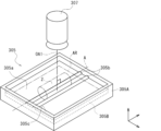
さが認識される(形状及び大きさの情報が取得される)。そのために、返品薬剤2は、図
1及び図13に示すように、半透明板305の載置面305a(カメラ307側の平面)
上に、その長手軸Aが載置面305aに対して平行になるように載置される。そして、半
透明板305上に載置された返品薬剤2は、半透明板305の下方に配置された照明30
6によって光が下方から照射された状態で、半透明板305の上方に配置されたカメラ3
07によって撮影される。
(Recognition of drug shape and size)
As described above, the
It is placed on top such that its longitudinal axis A is parallel to the
07.
制御装置1000は、カメラ307によって撮影された画像に基づいて、返品薬剤2の
形状及び大きさの情報を取得するように構成されている。すなわち、制御装置1000は
、返品薬剤2の形状及び大きさを認識するための認識部300の一部(第1薬剤情報取得
部)として機能する。
The
制御装置1000はまた、返品薬剤2の形状及び大きさの情報を取得するために、返品
薬剤2が写るカメラ307の画像を画像処理するように構成されている(画像処理部を有
する)。カメラ307の画像に対する画像処理として、例えば、その画像に写る返品薬剤
2の像のエッジを検出するためのエッジ検出処理と、画像を2値化(白黒化)する2値化
処理とが行われる。エッジ検出処理された画像と2値化処理された画像とに基づいて、制
御装置1000は、返品薬剤2の形状と大きさの情報を取得する。
The
また、制御装置1000は、取得した返品薬剤2の形状に基づいて、その返品薬剤2の
形状が返品薬剤供給装置1において取り扱い対象の薬剤の形状であるかを判定するように
構成されている。
Further, the
返品トレー4を介して返却される返品薬剤2に、例えば、ラベル読取部302における
無端ベルト308とローラ309との間に噛み込む形状の薬剤、スカラー型ロボット80
0が保持できない形状の薬剤、格納部500に格納できない形状の薬剤、すなわち返品薬
剤供給装置1がその構造を原因として取り扱うことができない形状の薬剤が含まれる場合
がある。一例として、袋体や箱体に収納された状態の薬剤、部分的に欠損している薬剤、
ラベルが部分的に剥離している薬剤、部分的に剥離したラベルが他の薬剤に貼り付いた薬
剤などが挙げられる。このような返品薬剤は、返品薬剤供給装置1ではその構造上取り扱
うことができないので、取り扱い対象外の薬剤(非格納薬剤)として処理される。
The returned
There are cases where medicines having a shape that cannot hold 0, medicines having a shape that cannot be stored in the
Drugs from which the label is partially peeled off, drugs from which the partially peeled label is attached to another drug, and the like are included. Such returned medicines cannot be handled by the returned
カメラ307の画像(画像処理済みの画像)に基づいて返品薬剤2の形状を判定する方
法の一例について説明する。
An example of a method for determining the shape of the returned
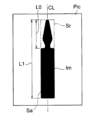
図28A及び図28Bは、2値化処理された画像を示している。図28Aは、返品薬剤
供給装置1の取り扱い対象の薬剤の形状であるアンプル形状の返品薬剤2の像(黒塗り像
)Imが写る2値化処理済みの画像Picを示している。図28Bは、取り扱い対象外の
薬剤の形状である、すなわちラベル3が部分的に剥離した状態のアンプル形状の返品薬剤
2の像(黒塗り像)Im’が写る2値化処理済みの画像Pic’を示している。
28A and 28B show binarized images. FIG. 28A shows a binarized image Pic in which an image (blackened image) Im of an ampoule-shaped returned
まず、制御装置1000は、カメラ307の画像Pic(Pic’)内において、黒塗
り像Im(Im’)に外接する矩形領域Sr(Sr’)を抽出する。次に、矩形領域Sr
(Sr’)の長手方向(長辺Sa(Sa’)が延在する方向)に延在する矩形領域Sr(
Sr’)の中心線CL(CL’)を算出する。そして、黒塗り像Im(Im’)が、中心
線CL(CL’)を基準にして対称の形状であるか否かを制御装置1000は判定する。
First, the
Rectangular area Sr (
Sr') center line CL (CL') is calculated. Then, the
図28Aの画像Picの場合、黒塗り像Imが中心線CLに対して対称の形状であるた
め、制御装置1000は、画像Picに写る返品薬剤2の形状を取り扱い対象の薬剤の形
状であると判定する。一方、図28Bの画像Pic’の場合、黒塗り像Im’が中心線C
L’に対して非対称の形状であるため、制御装置1000は、画像Pic’に写る返品薬
剤2の形状を取り扱い対象外の薬剤の形状であると判定する。
In the case of the image Pic of FIG. 28A , the black-painted image Im is symmetrical with respect to the center line CL. judge. On the other hand, in the case of the image Pic' of FIG. 28B, the black-painted image Im'
Since the shape is asymmetric with respect to L', the
また、代わりのまたは追加の判定方法として、矩形領域Srの長辺Saにおいて、黒塗
り像Imと接触していない部分を抽出し、その長さL0を算出する。すなわち、返品薬剤
2の頭部2dの長さを算出する。この長さL0と、矩形領域Srの長辺Saの長さ(すな
わち返品薬剤2の全長)L1とを比較することにより、カメラ307の画像に写る返品薬
剤2の形状が取り扱い対象の薬剤の形状であるか否かを判定することができる。例えば、
取り扱い対象の薬剤の全長に対する頭部長さの比が0.3~0.4の範囲である場合、L
0/L1の値が0.3~0.4の範囲内であれば、画像に写る返品薬剤2の形状は取り扱
い対象の薬剤の形状である。
As an alternative or additional determination method, a portion not in contact with the black-painted image Im is extracted from the long side Sa of the rectangular area Sr, and the length L0 thereof is calculated. That is, the length of the
If the ratio of the head length to the total length of the drug to be handled is in the range of 0.3 to 0.4, L
If the value of 0/L1 is within the range of 0.3 to 0.4, the shape of the returned
このほかにも、矩形領域Srの面積に対する黒塗り像Imの面積の比に基づいて、返品
薬剤2の形状が取り扱い対象の薬剤の形状であるか否かを判定することが可能である。
In addition, based on the ratio of the area of the black-painted image Im to the area of the rectangular region Sr, it is possible to determine whether or not the shape of the returned
さらにまた、取り扱い対象の薬剤の形状をデータとして予め保持し、その形状データと
画像における返品薬剤2の形状とを照合し、その照合結果(類似度)に基づいて返品薬剤
2の形状を判定することも可能である。
Furthermore, the shape of the medicine to be handled is stored in advance as data, the shape data is collated with the shape of the returned
なお、図29に示すような樹脂アンプル2(2C)の場合、取り扱い対象外の薬剤の形
状と判定される可能性がある。すなわち、円形状(または楕円形状、長円形状)の断面を
備える胴部2cと、長方形薄板状(または正方形薄板状)の頭部2dとを有する樹脂アン
プル2(2C)の場合、画像処理されたカメラ307の画像において長方形に写る場合が
ある。そのため、直方体形状の箱体に収納された薬剤と区別できない場合がある。
In the case of the resin ampoule 2 (2C) as shown in FIG. 29, there is a possibility that the shape of the resin ampoule 2 (2C) is determined to be the shape of a drug that is not to be handled. That is, in the case of the resin ampoule 2 (2C) having a
この場合、樹脂アンプル2(2C)が透明(または半透明)であって、箱体が不透明で
あることを利用する。すなわち、前者が光を透過し、後者が光を透過しない特性を利用す
る。
In this case, the fact that the resin ampoule 2 (2C) is transparent (or translucent) and the box is opaque is used. In other words, the former is permeable to light and the latter is not to permeate light.
具体的には、返品薬剤2が写るカメラ307の画像の輝度を上げる輝度調整処理を実行
した後に、その画像を2値化処理する。
Specifically, after performing brightness adjustment processing to increase the brightness of the image of the
カメラ307の画像に写る返品薬剤2が透明な樹脂アンプル2(2C)である場合、輝
度を上げる輝度調整処理により、画像に写る返品薬剤2の像の中央部分が白とびする。
その後に2値化処理を画像に実行すると、返品薬剤2の輪郭の像のみが画像上に残る。す
なわち、おおむね枠状の像が画像に残る。一方、箱体の場合、輝度調整処理を実行しても
、箱体の像は、部分的に白とびすることなく、そのままの形状が画像上に残る。そのため
、その後に2値化処理しても、長方形状の像が画像が残る。したがって、画像の輝度を上
げる輝度調整処理を行った後に2値化処理を行うことにより、その処理後の画像上におい
て、透明な(または半透明な)樹脂アンプル2(2C)と箱体とを区別することが可能で
ある。
When the returned
When the binarization process is then performed on the image, only the contour image of the returned
仮置き部301の半透明板305に載置された返品薬剤2が取り扱い対象の薬剤の形状
であることが判定された後、制御装置1000は、返品薬剤2の大きさが取り扱い対象の
薬剤の大きさ(サイズ)であるか否かを判定する。そのために、その返品薬剤2の大きさ
が測定(算出)される。
After it is determined that the returned-
返品トレー4を介して返却される返品薬剤2に、例えば、ラベル読取部302における
無端ベルト308とローラ309との間に噛み込む大きさの薬剤、スカラー型ロボット8
00が保持できない大きさの薬剤、格納部500に格納できない大きさの薬剤、すなわち
返品薬剤供給装置1がその構造を原因として取り扱うことができない大きさの薬剤が含ま
れる場合がある。このような返品薬剤2は、返品薬剤供給装置1ではその構造上取り扱う
ことができないので、取り扱い対象外の薬剤(非格納薬剤)として処理される。
The returned
00, or a size that cannot be stored in the
本実施形態の場合、返品薬剤2の大きさ(サイズ)の情報を取得するために、まず、返
品薬剤2の長手方向(軸線Aの延在方向)の長さが測定(算出)される。その返品薬剤2
の長手方向の長さの測定(算出)方法について説明する。
In this embodiment, in order to acquire information on the size of the returned
A method of measuring (calculating) the length in the longitudinal direction of is described.
図30及び図31は、返品薬剤2の大きさの測定(算出)方法を説明するための図であ
る。
30 and 31 are diagrams for explaining a method of measuring (calculating) the size of the returned
図30に示すように半透明板305上に載置された返品薬剤2(バイアル2B)がその
上方のカメラ307によって撮影されると、図31に示すようにカメラ307の画像Pi
cに返品薬剤2が写る。この画像Picに写る返品薬剤2の像の長手方向長さLmと幅方
向長さW1、W2とに基づいて、返品薬剤2の大きさとして、その長手方向(軸線Aの延
在方向)の実際の長さLactが算出される。カメラ307の画像Picに基づく、返品
薬剤2の長手方向の実際の長さLactの算出方法について説明する。
When the returned medicine 2 (
Returned
返品薬剤2のような円筒体をその軸線と直交する方向に撮影した場合、その軸線の延在
方向の大きさについて、画像上の大きさと実際の大きさとの間に誤差が生じる。具体的に
は、画像において、返品薬剤2は、実際の大きさに比べて大きく写る。
When a cylindrical body such as the returned
そのため、カメラ307の画像Picに基づいて返品薬剤2の長手方向(軸線Aの延在
方向)の大きさを算出する場合、画像Pic上における返品薬剤2の像の長手方向の大き
さを補正する必要がある。そのために、画像Pic上の大きさと実際の大きさとの間の誤
差E1、E2を求める必要がある。その誤差E1、E2の算出方法について説明する。
Therefore, when calculating the size of the returned
まず、図31に示すように、カメラ307の画像Picにおける返品薬剤2の長手方向
の長さLm、先端2aにおける幅方向の長さ(先端側幅)W1、及び基端2bにおける幅
方向の長さ(基端側幅)W2を算出する。
First, as shown in FIG. 31, the length Lm in the longitudinal direction of the returned
なお、カメラ307の画像Picにおける返品薬剤2の像の長手方向は、半透明板30
5上の実際の返品薬剤2の長手方向(軸線Aの延在方向)に対応する。また、画像Pにお
ける返品薬剤2の像の幅方向は、実際の返品薬剤2の径方向に対応する。
Note that the longitudinal direction of the image of the returned
5 corresponds to the longitudinal direction of the actual returned medicine 2 (extending direction of the axis A). Further, the width direction of the image of the returned
より具体的に言えば、カメラ307の画像Picにおける返品薬剤2の像の長手方向長
さとして、カメラ307の光軸OA1と先端2aとの間の長さ(先端側長さ)Lm1と、
光軸OA1と基端2bとの間の長さ(基端側長さ)Lm2とが算出される。この先端側長
さLm1と基端側長さLm2の合計が画像Picにおける返品薬剤2の像の長手方向長さ
Lmに相当する。
More specifically, as the length in the longitudinal direction of the image of the returned
A length (base end side length) Lm2 between the optical axis OA1 and the
カメラ307の画像Pic内の返品薬剤2の像における先端側長さLm1、基端側長さ
Lm2、先端側幅W1、及び基端側幅W2に基づいて、画像Picにおける返品薬剤2の
像の長手方向長さLmと返品薬剤2の実際の長手方向長さLactとの間の誤差E1、E
2を算出する。そのために、幾何学、具体的には三角形の相似を利用する。
Based on the distal side length Lm1, the proximal side length Lm2, the distal side width W1, and the proximal side width W2 in the image of the returned
2 is calculated. To that end, we use geometry, specifically the similarity of triangles.
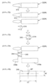
図30に示すように、三角形△A(p1-p2-p3)と三角形△B(p4-p2-p
5)とは相似である。また、三角形△Aは、その底辺の長さが先端側長さLm1であって
、その高さh0がカメラ307の結像点p1と半透明板305の載置面305aとの間の
距離である。一方、三角形△Bは、その底辺の長さが誤差E1であって、その高さがh1
である。高さh1は、数式1に示すように、先端2aの最下端と半透明板305の載置面
305aとの間の距離(W2-W1)/2と先端側幅W1との合計である。
As shown in FIG. 30, triangle ΔA (p1-p2-p3) and triangle ΔB (p4-p2-p
5) is similar. The triangle ΔA has a base length Lm1 and a height h0 which is the distance between the imaging point p1 of the
is. The height h1, as shown in
![]()
![]()
なお、数式1は、返品薬剤2がバイアル2Bであることから求めることができる。すな
わち、先端2a及び基端2bにおける返品薬剤2の端面形状が円形状平面であることから
求めることができる。
Note that
したがって、三角形△A、△Bの相似関係に基づいて、以下の数式2が成立する。
Therefore, based on the similarity relationship between triangles ΔA and ΔB,
![]()
![]()
同様に、三角形△C(p1-p6-p3)と三角形△D(p7-p6-p8)とは相似
である。また、三角形△Cは、その底辺の長さが基端側距離Lm2であって、その高さh
0がカメラ307の結像点p1と半透明板305の載置面305aとの間の距離である。
一方、三角形△Dは、その底辺の長さが誤差E2であって、その高さh2が基端側幅W2
である。
Similarly, triangle ΔC(p1-p6-p3) and triangle ΔD(p7-p6-p8) are similar. Also, the triangle ΔC has a base length Lm2 and a height h
0 is the distance between the imaging point p1 of the
On the other hand, the triangle ΔD has the length of the base with the error E2 and the height h2 with the base width W2.
is.
したがって、三角形△C、△Dの相似関係に基づいて、以下の数式3が成立する。
Therefore, based on the similarity relationship between triangles ΔC and ΔD,
![]()
![]()
数式1~3において、先端側距離Lm1、基端側距離Lm2、先端側幅W1、及び基端
側幅W2は、返品薬剤2が写るカメラ307の画像Picに基づいて算出される。また、
高さh0は、カメラ307の結像点p1と半透明板305の載置面305aとの間の距離
であるため、一定であって既知である。それらの値と数式1~3とを用いることにより、
先端2a側の誤差E1と基端2b側の誤差E2とを算出することができる。
In
Since the height h0 is the distance between the imaging point p1 of the
An error E1 on the side of the
この算出された誤差E1、E2をカメラ307の画像Picにおける返品薬剤2の像の
長手方向長さLm(Lm1+Lm2)から減算することにより、返品薬剤2の実際の長手
方向(軸線Aの延在方向)の長さLactを算出することができる。
By subtracting the calculated errors E1 and E2 from the longitudinal direction length Lm (Lm1+Lm2) of the image of the returned
このように返品薬剤2の実際の長手方向(軸線Aの延在方向)の長さを算出することが
できると、その前に取得した返品薬剤2の形状の情報に基づいて、返品薬剤2の他の部分
の実際のサイズも算出可能である。例えば、返品薬剤2がバイアル2Bの場合、胴部2c
の実際の外径を算出することができる。
If the length of the returned
can be calculated.
なお、上述するような返品薬剤2の長手方向の実際の長さの算出は、返品薬剤2の先端
2a及び基端2bでの端面がバイアル2Bのように円形状端面の場合に、その精度が高い
。したがって、返品薬剤2がアンプル2Aまたは樹脂アンプル2Cの場合、その長手方向
の実際の長さの算出方法を少し変更する必要がある。
It should be noted that the calculation of the actual length in the longitudinal direction of the returned
例えば、返品薬剤2がアンプル2Aの場合、その頭部2dが先端2aに向かって先細る
形状であるため、先端2aは平面ではなく点である。そのために、カメラ307の画像に
おけるアンプル2Aの像から、先端側幅W1を算出することはできない。すなわち、前述
の数式1、先端側幅W1、および基端側幅W2を用いて返品薬剤2(2A)の先端側の高
さh1を求めることができない。そこで、返品薬剤2がアンプル2Aの場合には、先端側
の高さh1を、基端側幅W2を用いて数式4に示すように定義する。
For example, when the returned
![]()
![]()
数式4において、αは定数であり、実験的または経験的に求められる。例えば、定数α
は1mmである。数式4、数式2、及び数式3を用いることにより、返品薬剤2がアンプ
ル2Aであっても、そのアンプルAが写るカメラ307の画像に基づいて、その長手方向
(軸線Aの延在方向)の実際の長さLactを算出することができる。
In
is 1 mm. By using
また、返品薬剤2が図29に示すように長方形薄板状(または正方形薄板状)の頭部2
dを有する樹脂アンプル2Cの場合も、アンプル2Aの場合と同様の方法で、その長手方
向(軸線Aの延在方向)の実際の長さLactを算出することが可能であり、またそれが
好ましい。その理由は、樹脂アンプル2Cの場合、半透明板305の載置面305aに対
する薄板状の頭部2dの傾きによって、カメラ307の画像上における先端側幅W1が異
なるからである。そのため、アンプル2Aと同様に、先端側幅W1を、基端側幅W2の関
数とみなすのが好ましい。
Moreover, as shown in FIG. 29, the returned
In the case of the
さらに、前述したように、樹脂アンプル2Cは、薄板状の頭部2dが半透明板305の
載置面305aに対して平行ではない状態(わずかに傾いた状態)で、半透明板305上
に載置される可能性がある。このような場合を考慮に入れて、カメラ307の画像上の樹
脂アンプル2Cの像における長手方向の長さLm(すなわち先端側距離Lm1及び基端側
距離Lm2)は、その像の幅方向の中心で測定されるのが好ましい。
Furthermore, as described above, the
さらに、返品薬剤2の長手方向の実際の長さLactを測定(算出)するにあたって、
カメラ307の光軸OA1と返品薬剤2とが交差するように、返品薬剤2は半透明板30
5の載置面305a上に位置決めされるのが好ましい。特に、カメラ307の光軸OA1
と返品薬剤2の軸線Aとが直交するように、返品薬剤2は半透明板305に対して位置決
めされるのが好ましい。
Furthermore, in measuring (calculating) the actual length Lact in the longitudinal direction of the returned
Returned
5 is preferably positioned on the mounting
and the axis A of the returned
例えば、図32は、返品薬剤2を位置決めするための位置決め部として凹凸部が形成さ
れている半透明板(薬剤載置板)305の斜視図である。
For example, FIG. 32 is a perspective view of a translucent plate (medicine mounting plate) 305 in which concave and convex portions are formed as positioning portions for positioning returned-
本実施形態の場合、半透明板305は、半透明のベースプレート305Aと、そのベー
スプレート305A上に載置され、返品薬剤2が載置される載置面305aを備える透明
の位置決めプレート305Bとから構成されている。ベースプレート305Aは、位置決
めプレート305Bの周囲から上方へ突出して、返品薬剤2の載置面305aからの脱落
を防止する、枠体305cを備えている。
In the case of this embodiment, the
位置決めプレート305Bは、ベースプレート305Aに着脱可能に取り付けられる。
位置決めプレート305Bはまた、カメラ307の光軸OA1と載置面305a上に載置
された返品薬剤2の軸線Aとが直交するように、返品薬剤2を半透明板305に対して位
置決めするための一対の直線状の突条部305bを備える。一対の直線状の突条部305
bは、間隔をあけて平行に延在し、カメラ307側に向かって載置面305aから突出し
ている。一対の突条部305bの間に返品薬剤2が配置されると、その胴部2cの外周面
に一対の突条部305bが当接する。それにより、返品薬剤2は、その軸線Aがカメラ3
07の光軸OA1に直交した状態で、半透明板305の載置面305aに対して位置決め
される。
The
The
b extend in parallel with a space therebetween and protrude from the
07 is positioned perpendicular to the optical axis OA1 of the
また、位置決めプレート305B(載置面305a)には、カメラ307の画像に基づ
いて返品薬剤2の位置、向き、形状及び大きさを解析する解析範囲ARが設定されている
。解析範囲ARは、載置面305aのうち、枠体305cから中央側に所定間隔離れた位
置に設定されている。すなわち、返品薬剤2は、載置面305aに載置され且つ突条部3
05bによって位置決めされた状態では、全体が解析範囲AR内に通常は位置する。しか
しながら、返品薬剤2は、返却トレー4から仮置き部301への移送時に、突条部305
bの延在方向に対して軸線が傾斜するように配置される場合がある。これは、例えば、返
却トレー4内における返品薬剤2のピッキング位置又は軸線方向の検出ミスが生じた場合
に発生する。この場合、仮置き部301の平面図を示す図33を参照して、返品薬剤2は
、突条部305bで位置決めされることはなく、突条部305bから周囲の枠体305c
まで転がり落ちて、解析範囲AR内からはみ出して、全体が解析範囲AR内に位置しなく
なる。この結果、制御装置1000は、返品薬剤2の形状及び大きさを正しく解析できな
い。
Further, an analysis range AR for analyzing the position, orientation, shape and size of the returned
05b, the whole is normally located within the analysis range AR. However, when the returned
In some cases, it is arranged so that the axis is inclined with respect to the extending direction of b. This may occur, for example, if a misdetection of the picking position or axial direction of the
It rolls down to and protrudes from the analysis range AR, and the whole is not positioned within the analysis range AR. As a result, the
この対応として、仮置き部301の側方断面図を示す図34を参照して、直交型ロボッ
ト700を動かして、吸着ノズル701で返品薬剤2を解析範囲ARの中央部側に移動さ
せると共に、この解析範囲AR内で返品薬剤2の向きを解析することによって、突条部3
05bに再位置決めするようになっている。以下、仮置き部301に移送された返品薬剤
2が、突条部305bによって位置決めされているか否かを判定すると共に、返品薬剤2
が突条部305bに位置決めされていない場合には再位置決めするまでの流れの一例を、
図35のフローチャート図を参照しながら説明する。
As a countermeasure, referring to FIG. 34 showing a side cross-sectional view of the
05b. Thereafter, it is determined whether or not the returned
is not positioned on the
Description will be made with reference to the flow chart of FIG.
まず、図35に示すように、ステップS101において、制御装置1000は、カメラ
307の画像に基づいて、返品薬剤2が位置する領域としての薬剤領域を抽出する。
First, as shown in FIG. 35, in step S101, the
次に、ステップS102において、制御装置1000は、薬剤領域の全てが解析範囲A
R内に位置しているか否かを判定する。薬剤領域の全てが解析範囲ARに位置している場
合にはステップS105に進み、そうでない場合にはステップS103に進む。
Next, in step S102, the
Determine whether it is located within R. If all of the drug regions are located within the analysis range AR, the process proceeds to step S105; otherwise, the process proceeds to step S103.
次に、ステップS103において、制御装置1000は、薬剤領域のうち、解析範囲A
R内に位置する領域を解析して、この領域の中心座標CCを算出する。
Next, in step S103, the
A region located within R is analyzed to calculate the center coordinates CC of this region.
次に、ステップS104において、制御装置1000は、直交型ロボット700を制御
して、返品薬剤2を、解析範囲AR内に全体が位置するように移動させる。具体的には、
図33及び34に示すように、返品薬剤2を、ステップS103で算出した中心座標CC
に対して、ベースプレート305Aの外側から中央部に向けて吸着ノズル701で押し出
して移動させる。
Next, in step S104, the
As shown in FIGS. 33 and 34, the returned
With respect to the
一方、ステップS102において薬剤領域の全てが解析範囲ARに位置すると判定され
た場合、ステップS105において、制御装置1000は、カメラ307の画像に基づい
て返品薬剤2が突条部305bに位置決めされているか、すなわちバックライトの中央位
置に位置するか否かを判定する。返品薬剤2がバックライトの中央に位置している場合に
はステップS107に進み、そうでない場合にはステップS106に進む。
On the other hand, if it is determined in step S102 that the entire drug region is located within the analysis range AR, in step S105, the
ステップS106において、制御装置1000は、カメラ307の画像に基づいて返品
薬剤2の向きを検出して、直交型ロボット700を制御して、返品薬剤2を、吸着ノズル
701で吸着して突条部305bに位置決めする。その際に、返品薬剤2の中心軸線Aが
、突条部305bの延在方向に沿うように返品薬剤2の軸線Aを向けて載置する。これに
よって、返品薬剤2が突条部305bで位置決めされたことになる。
In step S106, the
ステップS104において返品薬剤2が解析範囲ARに移動された後、及びステップS
106において返品薬剤2が突条部305bに位置決めされた後に、再度ステップS10
1において薬剤領域が抽出される。
After the returned
After the returned-
At 1, the drug region is extracted.
そして、ステップS102において薬剤領域が解析範囲AR内に位置していると判定さ
れ、ステップS105において返品薬剤2がバックライトの中央に位置していると判定さ
れた場合に、ステップS107において、制御装置1000は、載置面305a上で突条
部305bによって位置決めされた返品薬剤2に対して、カメラ307の画像に基づいて
、形状及び大きさを解析処理する通常の形状解析処理を実行する。
Then, when it is determined in step S102 that the medicine region is positioned within the analysis range AR and in step S105 it is determined that the returned
なお、半透明板305(すなわちカメラ307の光軸OA1)に対して返品薬剤2を位
置決めできるのであれば、半透明板305に形成される位置決め部は、図32に示す一対
の直線状の突条部305bに限らない。例えば、返品薬剤2を位置決めするための凹凸部
は、溝であってもよい。
If the returned
また、半透明板305を、ベースプレート305Aと位置決めプレート305Bとから
構成するのではなく、一枚の半透明なプレートによって構成してもよい。その場合、一枚
のプレート上に、返品薬剤2を位置決めするための凹凸部が形成される。ただし、半透明
板305をベースプレート305Aと位置決めプレート305Bとから構成する場合、返
品薬剤2を位置決めするための凹凸部の形状が異なる複数の位置決めプレートを用意する
ことにより、返品薬剤供給装置1は、より多様な形状及び大きさの薬剤を取り扱うことが
できる。
Also, the
認識部300の仮置き部301にて形状及び大きさが認識された返品薬剤2は、その形
状及び大きさが取り扱い対象の薬剤の形状及び大きさであると制御装置1000によって
判定された場合、図13に示すように仮置き部301に対して隣接するラベル読取部30
2に直交型ロボット700によって搬送される。
When the
2 by the
一方、形状が取り扱い対象外の薬剤の形状であると判定された返品薬剤2または形状が取
り扱い対象の薬剤の形状であっても大きさが取り扱い対象外の薬剤の大きさであると判定
された返品薬剤2は、非格納薬剤2’として、非格納薬剤配置部400の非格納薬剤配置
箱401、402または非格納薬剤用の返品トレー4に移載される。
On the other hand, the returned
(吸着位置の決定)
次に、図36~図38を参照して、仮置き部301のカメラ307によって撮影された
画像に基づいて(すなわち前述したように取得された返品薬剤2の形状及び大きさの情報
に基づいて)、返品薬剤2の吸着位置(直交型ロボット700の吸着ノズル701とスカ
ラー型ロボット800の吸着ノズル801で吸着される位置)を算出する方法を説明する
。
(Determination of adsorption position)
Next, referring to FIGS. 36 to 38, based on the image captured by the
図36を参照すると、バイアル2Bは、胴部2cからの頭部2dの突出量が比較的少な
く、胴部2cと頭部2dの径の差も小さいので、長さ(全長L1)の概ね中間位置を吸着
位置SPに設定すれば、吸着ノズル701,801で吸着した際に重量バランスは良好で
ある。つまり、バイアル2Bの場合、全長L1の概ね中間位置を吸着位置SPに設定すれ
ば、吸着ノズル701,801による保持が安定する。
Referring to FIG. 36, the
引き続き図36を参照すると、アンプル2Aは、胴部2cから頭部2dの突出量が比較
的大きく、胴部2cと頭部2dの径の差も大きいので、全長L1の概ね中間位置を吸着位
置SPに設定すると、吸着ノズル701,801で吸着した際に重量バランスが良好でな
い。アンプル2Aの場合、全長L1ではなく、胴部2cの長さL2の概ね中間位置を吸着
位置SPに設定すれば、吸着ノズル701,801で吸着した際に重量バランスは良好で
ある。つまり、アンプル2Aの場合、胴部2cの長さL2の概ね中間位置を吸着位置SP
に設定すれば、吸着ノズル701,801による保持が安定する。この点は、樹脂アンプ
ル2Cの場合も同様である。
Continuing to refer to FIG. 36, in the
, the holding by the
以上の理由から、仮置き部301のカメラ307によって撮影された画像に基づいて、
以下の手順により返品薬剤2の吸着位置SPが算出される。
For the above reasons, based on the image captured by the
The adsorption position SP of the returned
まず、カメラ307で撮影された画像(返品薬剤2の平面視での画像)の外形輪郭に対
する包絡線(または外接矩形)313が設定される(図37及び図38のステップ1)。
また、この包絡線313から凸面度が算出される(図37及び図38のステップ1)。凸
面度は包絡線313が直線で返品薬剤2を囲むことができる程、値が1に近づく。すなわ
ち、凸面度の値(最大値は1)が大きい程、胴部2cと頭部2dの径の差が少なく、胴部
2cと頭部2dをつなぐ首部の胴部2c及び頭部2dに対する径の差も小さいことを意味
する。
First, an envelope (or circumscribing rectangle) 313 is set for the contour of the image (the image of the returned
Also, the degree of convexity is calculated from this envelope 313 (
算出された凸面度の値が、予め設定された閾値(例えば0.8~0.9の範囲で設定で
きる)以上であるならば、カメラ307で撮影した返品薬剤2は、バイアル2Bと推定で
きる形状を有すると判断できるので、全長L1の中間、かつ幅Wの中間を吸着位置SPに
設定する(図37のステップ2)。
If the calculated convexity value is equal to or greater than a preset threshold value (which can be set in the range of 0.8 to 0.9, for example), the returned
算出された凸面度の値が、前述の予め設定された閾値未満であれば、カメラ307で撮
影した返品薬剤2は、アンプル2A(あるいは樹脂アンプル2C)と推定できる形状を有
すると判断できるので、胴部2cの長さL2の中間を吸着位置SPに設定するために、以
下の処理を行う。
If the calculated convexity value is less than the preset threshold, it can be determined that the returned
まず、包絡線(または外接矩形)313と返品薬剤2の画像の外形輪郭との比較により
、胴部2cと頭部2dとの間の首部(部分的に縮径している部分)に相当する、括れ部分
314を抽出する(図38のステップ2)。
First, by comparing the envelope (or circumscribing rectangle) 313 with the outline of the image of the returned
次に、抽出された括れ部分314を直線で囲む矩形領域315を作成する(図38のス
テップ3)。
Next, a
その後、返品薬剤2の画像の外形輪郭から矩形領域315を除去することで、2つの領
域316a,316bを作成する(図38のステップ4)。これらの領域316a,31
6bは、返品薬剤2の画像の外形輪郭の括れ部分314以外の領域に相当する。また、こ
れらの領域316a,316bの一方が返品薬剤2の胴部2cに相当し、他方が頭部2d
に相当する。領域316a,316bの面積を比較し、面積が大きい方(胴部2cに相当
)を処理対象として残し、面積が小さい方(頭部2dに相当)を処理対象から除外する。
この例では、領域316aの面積が領域316bの面積よりも大きいので、領域316a
を処理対象として残す。
After that, by removing the
6b corresponds to a region other than the
corresponds to The areas of the
In this example, the area of
is left for processing.
最後に、領域316aの長さL2’(アンプル2Aの胴部2cの長さL2に相当)の中
間と幅W’(アンプル2Aの胴部2cの幅Wに相当)の中間を吸着位置SPに設定する(
図38のステップ5)。
Finally, the midpoint between the length L2′ (equivalent to the length L2 of the
step 5) in FIG.
以上の手順により、仮置き部301のカメラ307によって撮影された画像に基づいて
、返品薬剤2を吸着ノズル701,801で安定して保持できる吸着位置SPを自動的に
決定できる。その結果、直交型ロボット700は、仮置き部301の半透明板305上に
載置された返品薬剤2を、その軸線Aが水平方向に対して平行な状態でラベル読取部30
2に搬送することができ、その頭部2dの先端を衝突させることなく認識部300のラベ
ル読取部302の無端ベルト308上に安全に載置することができる。また、詳細は後述
するが、直交型ロボット700は、無端ベルト308上に載置された返品薬剤2の基端2
bがラベル読取部302のストッパ317に対向するように、返品薬剤2を無端ベルト3
08上に載置することができる。
By the above procedure, based on the image photographed by the
2, and can be safely placed on the
Returned
08.
図39は、認識部300の模式図である。認識部300は、撮影部1003、制御演算
部1004、及び移送部1005を備える。撮影部1003は、カメラ304及びカメラ
304により撮影した画像データを伝送する機能を有する部分を備える。制御演算部10
04は制御装置1000に含まれており、CPU(Central Processing Unit)、RAM(R
andom Access Memory)、ROM(Read Only Memory)のような記憶装置を含むハードウ
ェアと、それに実装されたソフトウェアにより構築されている。移送部1005は、直交
型ロボット700を備える。
FIG. 39 is a schematic diagram of the
04 is included in the
It is composed of hardware including storage devices such as anatomic access memory) and ROM (Read Only Memory), and software implemented in the hardware.
具体的には、撮影部1003においてカメラ304で撮影された画像データが制御演算
部1004に伝送され、この画像データに基づいて、制御演算部1004が移送部100
5の直交型ロボット700を駆動制御し、返品トレー4中の返品薬剤2を1個ずつ吸着保
持し、仮置き部301の半透明板305上に移送する(図13参照)。制御演算部100
4は、2値化処理部1006、認識処理部1007、及び駆動制御部1008を備える。
Specifically, image data captured by the
The
4 includes a
2値化処理部1006は、撮影部1003のカメラ304で撮影された画像データを受
け取り、これを2値化処理することで2値化画像(第1の2値化画像)を生成する。図4
0A及び図40Bはそれぞれ、カメラ304で撮影された元の画像と所定の閾値(例えば
125)で2値化処理された2値化画像を例示する模式的な平面図である。図40Aの3
つの返品薬剤2のように円柱形状でその表面が曲面の場合、上方からの照明光を強く反射
する領域は細長くなる。このため、図40Bのように2値化画像において細長い照返領域
S1が認識され得る。
A
0A and 40B are schematic plan views respectively exemplifying the original image captured by the
In the case of a cylindrical shape with a curved surface, such as the two returned
2値化処理は、閾値を変化させて照返領域S1の検出を複数回行う。本実施形態では、
3段階で閾値を徐々に小さく変化させて照返領域S1を検出する。この場合、一段階目の
処理では閾値を高く(例えば245)設定することで、返品薬剤2の円柱形状の最も高く
なっている部分のみを検出できる。従って、返品薬剤2同士が接触している場合や部分的
に重なり合っている場合のように返品薬剤2の輪郭が不明瞭である場合でも、各返品薬剤
2の細長い照返領域S1は別領域として検出でき、これに基づいて返品薬剤2の位置等を
正確に検出できる。次に2段階目の処理では、1段階目よりも閾値を下げて(例えば12
5)2値化処理を行い、一段階目で検出できなかった少し暗い色の返品薬剤2を検出する
。3段階目の処理では、最も暗い色の返品薬剤2(例えば、茶色の瓶等)を検出できる程
度に閾値を低く(例えば75)設定し、残った薬品を検出する。複数の照返領域S1を検
出した場合は、最も面積の大きい照返領域S1を優先して移送するように制御することで
、吸着しやすい大きな返品薬剤2から順に吸着できる。また、検出した領域の重心位置を
出す際に、同時に領域の最少外接矩形の向きを検出することで返品薬剤2の向きも同時に
検出するようにしてもよい。なお、前記段階的処理については同じ画像を採用してもよい
し、個々に撮影し直した画像を利用してもよい。
In the binarization process, the threshold value is changed and the detection of the reflection region S1 is performed multiple times. In this embodiment,
The threshold value is gradually decreased in three steps to detect the illuminated region S1. In this case, by setting a high threshold value (for example, 245) in the first stage of processing, only the highest columnar portion of the returned
5) Binary processing is performed to detect the slightly dark returned
認識処理部1007は、2値化画像に基づいて返品薬剤2の位置、向き(XY平面にお
いて軸線Aが延びる方向であって先端2aと基端2bが向いている方向は含まない)、返
品薬剤2の略中間位置を検出する。通常、返品薬剤2の形状は、長さL1に対して幅Wが
短い(図8参照)。従って、検出した照返領域S1の位置等から、返品トレー4中の返品
薬剤2の位置等が認識される。
Based on the binarized image, the
返品薬剤2は、重心との位置関係上、胴部の中間位置を吸着されることが好ましい場合
がある。例えば、図40Aに示されている樹脂アンプル2Cは、胴部の中間位置を吸着す
ることが好ましい。しかし、樹脂アンプル2Cのように頭部に平面部を有する場合、頭部
で照明光を強く反射して照返領域S1を形成する場合がある。このような場合に直交型ロ
ボット700が誤って頭部を吸着することを防止するために、認識処理部1007は、2
値化画像上から頭部領域を認識除去領域として判定する領域判定部1009を備え、この
領域を位置検出対象から除外することが好ましい。
Due to the positional relationship with the center of gravity, the returned
It is preferable to provide an
具体的には、返品薬剤2の円柱形状の部分の照返領域S1は細長い領域である。即ち、
長さが所定の値以上、幅が所定の値未満、又は幅に対する長さの割合が所定の値以上であ
る。これに対し、図40Aの樹脂アンプル2Cの頭部の照返領域S1は、幅DWが大きく
、長さDLが小さい領域であり、幅DWに対する長さDLの割合が小さい。従って、領域
判定部1009での判定は、照返領域S1の長さDLが所定の値未満であるか、幅DWが
所定の値以上であるか、又は幅DWに対する長さDLの割合が所定の値以下である場合、
その領域を認識除去領域として判定する。ここで使用する所定の値は、使用する樹脂アン
プル2Cのサイズに応じて決定すればよい。このようにして、頭部を認識除去領域として
判定することで吸着すべき胴部を正確に認識できる。ここで検出された返品薬剤2の位置
等のデータは、駆動制御部1008に伝送される。
Specifically, the illumination return region S1 of the cylindrical portion of the returned
The length is greater than or equal to a predetermined value, the width is less than a predetermined value, or the ratio of length to width is greater than or equal to a predetermined value. On the other hand, the reflection region S1 of the head portion of the
The area is determined as a recognition removal area. The predetermined value used here may be determined according to the size of the
駆動制御部1008は、認識処理部1007で検出した返品薬剤2の位置等の情報に基
づいて、直交型ロボット700を駆動して返品薬剤2を仮置き部301の半透明板305
(図13参照)上に移送する制御を行う。移送の際には、返品薬剤2のサイズ及び表面に
貼付されたラベル情報等を自動認識する必要があるため、返品薬剤2は返品トレー4内で
倒れている必要がある。従って、返品トレー4内で倒れていない返品薬剤2が存在する場
合、駆動制御部1008は直交型ロボット700を駆動して返品薬剤2を倒すように制御
している。
The
(Refer to FIG. 13) Control to move upward is performed. Since it is necessary to automatically recognize the size of the returned
返品薬剤2が返品トレー4内で倒れているか否かの認識は、カメラ304で撮影した画
像、又はこれを2値化処理した2値化画像に基づいて認識処理部1007により行われる
。具体的には、倒れていない返品薬剤2は、上方のカメラ304で撮影した場合、他の返
品薬剤2と異なり、平面視で略円形である。従って、形状認識により返品薬剤2が倒れて
いるか判断する。または、倒れていない返品薬剤2は、他の倒れている返品薬剤2と比べ
て平面視での面積が小さいため、検出した返品薬剤2の面積が所定の面積以下の場合に倒
れていないと判断してもよい。このように、カメラ304で撮影した画像、又は2値化画
像に基づいて返品薬剤2が返品トレー4内で倒れているか否かを認識できる。
Recognition of whether or not the returned
次に、倒れていないと認識された返品薬剤2が存在する場合、駆動制御部1008が直
交型ロボット700を制御して返品薬剤2を倒す方法を詳細に説明する。まず、図41A
に示すように、駆動制御部1008は、倒れていないと認識された返品薬剤2に対して、
直交型ロボット700を駆動して吸着パッド702を上方から返品薬剤2に押し当て返品
薬剤2の高さを測定する。高さの測定には、キャリッジ706に搭載された位置センサ(
図示せず)を使用してもよい。次に、吸着パッド702を一度上昇させて、吸着パッド7
02と返品薬剤2との接触を解除した後、数mm程度(例えば20mm程度)水平移動す
る。そして、測定した返品薬剤2の高さから数mm程度(例えば5mm程度)低い位置ま
で吸着パッド702を下降させた後、吸着パッド702を返品薬剤2へ向かって水平移動
させ、図41Bに示すように返品薬剤2の上部を押圧することで返品薬剤2を倒す。また
、一般に倒れていない返品薬剤2の高さは倒れている返品薬剤2の高さに比べて高いため
、測定した返品薬剤2の高さが所定の値以上の場合のみ、返品薬剤2が倒れていないと判
定してもよい。
Next, a detailed description will be given of how the
, the
The
not shown) may be used. Next, the
After releasing the contact between 02 and the returned
図42は、返品薬剤2を倒す方向を示す図である。図42に矢印で示すように、返品薬
剤2を倒す方向は、認識処理部1007で他の返品薬剤2がないと認識した方向であるこ
とが好ましい。これにより、倒れていない返品薬剤2の周囲で返品薬剤2がない方向を予
め確認することで移送部1005が吸着しやすく安全な方向に返品薬剤2を倒すことがで
きる。返品薬剤2を倒す方向を考慮しない場合、返品薬剤2を倒す方向によっては、倒し
た返品薬剤2が他の返品薬剤2と接触して破損する可能性や、返品薬剤2同士が表面のラ
ベルシールにより接着されてしまう可能性がある。これを防止するため、予め返品薬剤2
を倒す方向に他の返品薬剤2がないことを確認することは有効である。このようにして、
返品トレー4内で全ての返品薬剤2を倒れている状態とすることで、直交型ロボット70
0の吸着ノズル701が返品トレー4中の返品薬剤2を1個ずつ吸着保持し、仮置き部3
01の半透明板305上に移載できる(図13参照)。この際、吸着ノズル701は、そ
れ自体の軸線(Z軸)回りの回転により、吸着保持した返品薬剤2の向きを調節できる。
FIG. 42 is a diagram showing the direction in which the returned
It is effective to confirm that there are no other returned
By setting all the returned
No. 0
01 semitransparent plate 305 (see FIG. 13). At this time, the
直交型ロボット700が返品薬剤2を吸着して持ち上げる際、返品薬剤2の位置検出誤
差や直交型ロボット700のティーチング誤差により、吸着を失敗することがある。この
ため、吸着の成否を判断するために、制御演算部1004は吸着判定部1010を備える
ことが好ましい。吸着判定部1010は、吸着ノズル701内の圧力を測定する圧力セン
サ1012に基づいて吸着成否を判定する。吸着が成功すると、吸着パッド702の開口
部を返品薬剤2が閉塞するため、吸着ノズル701内への空気の吸い込みが行われず、吸
着ノズル701内の圧力は低下する。従って、直交型ロボット700による吸着動作後、
圧力センサ1012の出力が所定の値未満となった場合には吸着成功と判定し、圧力セン
サ1012の出力が所定の値以上である場合には吸着失敗と判定する。
When the
When the output of the
吸着判定部1010が吸着失敗と判定した場合、吸着位置の付近の所定の範囲内で吸着
位置及び角度を変更して複数回吸着動作を繰り返すことが好ましい。このような動作例と
しては以下の表1の例1~8のような吸着位置を指定する方法が挙げられる。
When the

各ステップにおいて移動する数値を具体的に設定する場合、返品薬剤2を考慮すること
が好ましい。小さな返品薬剤2に対しては吸着を失敗する可能性がより高い。本実施形態
で使用する返品薬剤2のサイズは、最小サイズで直径10mm、長さ35mm程度である
。従って、このサイズに基づいて上記の各ステップの数値は、幅W方向に10mmを越え
ない程度、又長さL方向には35mmを越えない程度の範囲であることが好ましい。
When specifically setting the numerical value to be moved in each step, it is preferable to consider returned
このように、吸着動作を失敗しても吸着位置を変更して再度吸着動作を行うため、返品
薬剤2の吸着成功確率を向上できる。特に小さいサイズの返品薬剤2を吸着する場合、高
精度の位置検出及び吸着動作が求められる。このような小さい返品薬剤2に合わせて吸着
位置を変更して吸着を行う動作を予め設定することで、吸着成功確率をより向上できる。
また、吸着を失敗しても再度画像認識及び2値化処理を行うことなく、吸着動作を行うた
め、効率よく薬剤の吸着及び移送を行うことができる。
In this way, even if the adsorption operation fails, the adsorption position is changed and the adsorption operation is performed again, so the probability of successful adsorption of the returned
Moreover, even if the adsorption fails, the adsorption operation is performed without performing the image recognition and the binarization processing again, so the adsorption and transfer of the medicine can be performed efficiently.
2値化処理部1006において、輝度値の高い順に2値化処理を行い、認識処理部10
07で返品薬剤2の位置等を検出する場合、一度吸着を失敗すると何度も同じ位置座標を
検出し、吸着失敗を繰り返す場合がある。従って、制御演算部1004は、2値化画像に
おいて吸着失敗と吸着判定部1010で判定された座標領域を記憶する記憶部1011を
備え、この座標領域では一時的に吸着しない制御を行うことが好ましい。これに代えて、
2値化画像において吸着失敗と前記吸着判定部1010で判定された座標領域を図示しな
い上位のシステムに記憶してもよい。
In the
When detecting the position or the like of the returned
Coordinate regions determined by the
図43は、本実施形態における認識部300における処理の一部を表すフローチャート
である。処理を開始すると、カメラ304により撮影を行い、2値化画像を生成する。記
憶部1011で記憶した前回吸着失敗した座標領域が存在する場合、この座標領域を含む
照返領域S1(図40B参照)を2値化画像に対してマスクする。前回吸着を失敗した座
標領域が存在しない場合はマスク処理を行わない。そして、2値化画像上で返品薬剤2が
検出された場合、吸着動作を行う。吸着判定部1010により吸着成功と判定されると再
び撮影を行い、反対に吸着失敗と判定されると記憶部1011に吸着を失敗した座標領域
を記憶する。記憶した座標が所定数未満である場合は撮影に戻る。記憶した座標が所定数
となった場合、かつそれが2回目の場合は処理を終了し、2回目でない場合はマスクをク
リアして撮影に戻り認識動作を開始する。吸着失敗と判定された場合には、先に記載の表
1のように吸着周辺位置を探索し吸着動作を行うようにしてもよい。これを繰り返し、2
値化画像上で返品薬剤2が検出されなくなった場合、吸着失敗した座標領域が記憶部10
11にない場合、処理を完了する。吸着失敗した座標領域が記憶部1011にある場合、
記憶されている全座標が記憶された回数が2回目であるならば処理を終了し、そうでない
ならばマスクをクリアして撮影に戻って認識動作を開始する。認識動作とは、撮影、2値
化処理、マスク処理、返品薬剤2の検出、及び、吸着失敗した座標領域を記憶部1011
に記憶する動作をいう。
FIG. 43 is a flow chart showing part of the processing in the
When the returned
11, complete the process. If the coordinate area for which adsorption failed exists in the
If the number of times that all the stored coordinates have been stored is the second time, the processing is terminated. The recognition operation includes photographing, binarization processing, mask processing, detection of the returned
It refers to the operation of storing in
このようにして、2値化画像上の吸着を失敗した座標領域を位置検出対象から一時的に
除外するため、吸着を失敗する座標領域を繰り返し検出することなく、他の薬剤の位置を
検出できる。特に大きなアンプルの場合、一度吸着に失敗した座標領域であっても何度も
位置検出される可能性があり、その吸着位置を認識対象から除外することで、吸着失敗回
数を低減でき、効率化を図ることができる。
In this way, the coordinate region where adsorption fails on the binarized image is temporarily excluded from the position detection target, so the position of another drug can be detected without repeatedly detecting the coordinate region where adsorption fails. . Particularly in the case of large ampoules, even if the coordinate area has failed to be adsorbed once, the position may be detected many times. can be achieved.
制御装置1000はまた、カメラ307によって撮影された画像に基づいて、返品薬剤
2の形状及び大きさの情報を取得するように構成されている。すなわち、制御装置100
0は、返品薬剤2の形状及び大きさを認識するための認識部300の一部として機能する
。
The
0 functions as part of the
制御装置1000はまた、返品薬剤2の形状及び大きさの情報を取得するために、返品
薬剤2が写るカメラ307の画像を画像処理するように構成されている(画像処理部を有
する)。カメラ307の画像に対する画像処理として、例えば、その画像に写る返品薬剤
2の像のエッジを検出するためのエッジ検出処理と、画像を2値化して2値化画像(第2
の2値化画像)を取得する2値化処理とが行われる。エッジ検出処理された画像と2値化
画像とに基づいて、制御装置1000は、返品薬剤2の形状と大きさの情報を取得する。
The
binarization processing for obtaining a binarized image of ) is performed. Based on the edge detection processed image and the binarized image, the
(薬剤の種類及び使用期限の認識)
前述したように、認識部300のラベル読取部302において、返品薬剤2の種類及び
使用期限が認識される(種類及び使用期限の情報が取得される)。そのために、ラベル読
取部302は、図14に示すように、返品薬剤2が載置される無端ベルト308と、無端
ベルト308上に載置された返品薬剤2と当接し、その返品薬剤2をその軸線Aを中心と
して回転させるローラ309とを有する。また、ラベル読取部302は、無端ベルト30
8を駆動するベルト駆動部(図示せず)と、ローラ309を駆動するローラ駆動部(図示
せず)とを有する。ベルト駆動部及びローラ駆動部は、例えばモータであって、制御装置
1000によって制御される。
(Recognition of drug type and expiry date)
As described above, the
8 and a roller drive (not shown) for driving the
ラベル読取部302の正面図である図44に示すように、ローラ309は、無端ベルト
308の上方に間隔をあけて、例えば1mmの間隔をあけて配置されている。また、図1
4に示すように、無端ベルト308の進行方向Fは、ローラ309の回転中心線Rcの延
在方向(Y軸方向)に対して非直交に交差している。例えば、本実施形態の場合、ローラ
309の回転中心線Rcの延在方向と無端ベルト308の進行方向Fとの間の角度は、5
~15度の範囲である。
As shown in FIG. 44, which is a front view of the
4, the traveling direction F of the
~15 degrees.
無端ベルト308の進行方向Fは、その上に載置された返品薬剤2がローラ309に接
近する方向である。一方、ローラ309の回転方向は、無端ベルト308との対向領域に
おいて、無端ベルト308の進行方向FのX方向成分に対して周速が逆方向になるような
回転方向である。
The advancing direction F of the
また、本実施形態の場合、無端ベルト308とローラ309との対向領域において、無
端ベルト308の移動速度とローラ309の回転速度が同一になるように、無端ベルト3
08及びローラ309は、制御装置1000によってベルト駆動部及びローラ駆動部を介
して駆動制御されている。
Further, in the case of the present embodiment, the
08 and
このような無端ベルト308とローラ309によれば、無端ベルト308上に載置され
た返品薬剤2は、無端ベルト308によって運ばれ、ローラ309に接触する。これによ
り、返品薬剤2は、ローラ309に当接した状態で維持され、X軸方向に関して位置決め
される。
With the
なお、返品薬剤2(特にアンプル2Aや樹脂アンプル2C)は、ローラ309に当接し
た状態のときにその基端2bがストッパ317に対向するような向きで、無端ベルト30
8上に直交型ロボット700によって載置されるのが好ましい。仮にアンプル2Aや樹脂
アンプル2Cの先端2a(頭部2d)がストッパ317側に位置する向きで無端ベルト3
08上に載置された場合、無端ベルト308の搬送が開始されることによってその胴部2
cの基端2b側の角部が先にローラ309に接触し、その接触した反動によって無端ベル
ト308上で向きが変わり、その頭部2dが無端ベルト308とローラ309との間に入
り込む可能性がある。したがって、返品薬剤2の頭部2dが無端ベルト308とローラ3
09との間に入り込む可能性がある場合には、その返品薬剤2は、ローラ309に当接し
た状態のときにその基端2bがストッパ317に対向するような向きで、無端ベルト30
8上に直交型ロボット700によって載置されるのが好ましい。
Note that the returned medicine 2 (especially the
8 by an
08, the
The
09, the returned
8 by an
図14に示すように無端ベルト308の進行方向Fとローラ309の回転中心線Rcの
延在方向とが非直交に交差するため、ローラ309に当接した後の返品薬剤2はローラ3
09にガイドされて該ローラ309の回転中心線Rcの延在方向(Y軸方向)に移動する
。最終的には、返品薬剤2の軸線Aの延在方向の一端がストッパ317に当接し、それに
より、返品薬剤2は、ローラ309の回転中心線Rcの延在方向(Y軸方向)に関して位
置決めされる。その結果、返品薬剤2は、ラベル読取部302に対して位置決めされる。
As shown in FIG. 14, since the traveling direction F of the
09 and moves in the extending direction of the rotation center line Rc of the roller 309 (Y-axis direction). Finally, one end of the returned
無端ベルト308の進行方向Fとローラ309の回転中心線Rcの延在方向とが非直交
に交差するような無端ベルト308に対するローラ309の配置およびストッパ317に
より、返品薬剤2は高精度に位置決めされた状態で維持される。
Returned
仮に、無端ベルト308の進行方向Fとローラ309の回転中心線Rcの延在方向とが
直交する場合、ローラ309に当接した状態の返品薬剤2は、ローラ309の回転中心線
Rcの延在方向に移動し、ストッパ317から離間する可能性がある。このことを考慮し
て、ストッパ317と返品薬剤2との当接状態を維持するために、無端ベルト308の進
行方向Fとローラ309の回転中心線Rcの延在方向とが非直交に交差している。
If the advancing direction F of the
返品薬剤2が高精度に位置決めされた状態で維持されることにより、例えば、ラベル読
取部302のカメラ311視野内に返品薬剤2が維持されるとともに、バーコードリーダ
312の読取可能領域内に返品薬剤2のラベル3のバーコードがセットされて維持される
。その結果、カメラ311とバーコードリーダ312による返品薬剤2の種類と使用期限
に対して高い認識精度を確保することができる。
By maintaining the returned
図45Aは、ローラ309の回転中心線Rcと直交する方向であって且つ無端ベルト3
08と平行な方向に見た、すなわち図14のX軸方向に見たラベル読取部302を示して
いる。
45A shows the direction orthogonal to the rotation center line Rc of the
08, ie along the X-axis of FIG. 14, is shown.
図45Aに示すように、返品薬剤2と当接するストッパ317の接触部は、ローラ30
9に当接した状態の返品薬剤2の軸線Aに対して直交する平面(Z-X平面と平行な平面
)ではない。
As shown in FIG. 45A , the contact portion of the
It is not a plane (a plane parallel to the ZX plane) perpendicular to the axis A of the returned
具体的には、返品薬剤2と当接するストッパ317の接触部は、2つの平面317a、
317bの間に形成されるエッジ部317cである。平面317aは、返品薬剤2と当接
する無端ベルト308の表面の法線に対して角度θ(すなわち鉛直方向(Z方向)に対し
て角度θ)で且つ無端ベルト308に対向するように傾いたオーバーハング面である。角
度θは、例えば15度である。2つの平面317a、317bの間のエッジ部317cは
、図14に示すように、ローラ309の回転中心線Rcに対して直交し、且つ無端ベルト
308の表面に対して平行に延在する、すなわちX方向に延在する。なお、ストッパ31
7のエッジ部317cの先端は、アール加工されている。
Specifically, the contact portion of the
The tip of the
X方向に延在するエッジ部317cは、返品薬剤2の基端2bに対して線接触する。こ
れにより、回転中の無端ベルト308及びローラ309に当接している返品薬剤2は、そ
の軸線Aが無端ベルト308の表面に対して且つローラ309の回転中心線Rcに対して
平行に維持された状態で、軸線Aを中心にして回転することができる。
The
このことを具体的に説明するために、比較例の図45Bに示すように、返品薬剤2と当
接するストッパ317’の接触部が平面部317a’である場合を考える。また、図45
Bに示すように、返品薬剤2の重心が頭部2d側に位置し、そのために傾いた状態(軸線
Aが無端ベルト308の表面に対して且つローラ309の回転中心線Rcに対して非平行
な状態)で返品薬剤2がストッパ317’の平面部317a’に接触する場合を考える。
なお、このような傾きは、胴部2cと頭部2dの大きさが近く、軽量な小さいサイズの返
品薬剤2に発生しやすい。
In order to specifically explain this, as shown in FIG. 45B of the comparative example, consider the case where the contact portion of the stopper 317' that contacts the returned
As shown in B, the center of gravity of the returned
In addition, such an inclination is likely to occur in the returned
図45Bに示すように、傾いた状態の返品薬剤2が、無端ベルト308とローラ309
の回転によってストッパ317’に向かって送られ(白抜矢印方向に送られ)、ラベル読
取部302’のストッパ317’の平面部317a’に接触する。傾いた状態であるため
に、返品薬剤2の基端2bの縁が、ストッパ317’の平面部317a’に接触する。
As shown in FIG. 45B , returned
is sent toward the stopper 317' (sent in the direction of the outline arrow) by the rotation of the label reading section 302', and contacts the
基端2bの縁がストッパ317’の平面部317a’に接触した状態で、返品薬剤2が
、無端ベルト308とローラ309とによって回転されると、基端2bの縁部とストッパ
317’の平面部317’との間に強い摩擦が発生する(返品薬剤2が傾くことなく、そ
の基端2b全体がストッパ317’の平面部317a’に接触する場合に比べて)。この
摩擦は、無端ベルト308とローラ309の回転によって返品薬剤2がストッパ317に
向かって付勢され続けられていることによって発生する。
When the returned-
返品薬剤2の基端2bの縁とストッパ317’の平面部317a’との間に摩擦が発生
すると、ストッパ317’の平面部317a’上を基端2bが転動する。
When friction occurs between the edge of the
この転動について、理解しやすい自動車のタイヤを例に挙げて説明する。自動車のタイ
ヤは、地面と接触しているタイヤの部分がまずあって、この部分に隣接するタイヤの部分
が該タイヤの回転によって次に地面に接触することにより、地面上を転動することができ
る。
This rolling will be explained by taking an automobile tire as an example, which is easy to understand. An automobile tire rolls on the ground by first having a portion of the tire in contact with the ground and then a portion of the tire adjacent to this portion contacting the ground as the tire rotates. can.
このタイヤのメカニズムと同様に、ストッパ317’の平面部317a’に接触してい
る基端2bの縁の部分がまずあって、この部分に隣接する基端2bの縁の部分が返品薬剤
2の回転によって次に平面部317a’に接触することにより、基端2bがストッパ31
7’の平面部317a’上を転動する。
Similar to this tire mechanism, there is first a portion of the edge of the
It rolls on the
基端2bがストッパ317’の平面部317a’上を転動すると、ストッパ317’に
対する返品薬剤2の相対位置が変化し、最終的には、返品薬剤2は、ストッパ317’や
ローラ309から離間する。その離間した返品薬剤2は、無端ベルト308によって送ら
れて再びローラ309に接触し、その後、無端ベルト308とローラ309によってスト
ッパ317’に向かって送られ、再度ストッパ317’の平面部317a’に接触する。
この再度の接触のときに返品薬剤2が傾いた状態であれば、その基端2bがストッパ31
7’の平面部317a’上を再び転動し、再び返品薬剤2がストッパ317’やローラ3
09から離間する。このようなループは、偶然的に返品薬剤2の傾きが解消されるまで続
く。その結果、ラベル読取部302において、ラベルに記載された使用期限やバーコード
の認識の開始が遅れるまたは開始不能になる。
When the
If the returned
7' rolls on the
09 away. Such a loop continues until the inclination of returned
このような傾きやすい返品薬剤2に起こる問題を考慮して、図45Aに示すように、本
実施形態のラベル読取部302のストッパ317は、そのエッジ部317cを介して返品
薬剤2と接触するように構成されている。
In consideration of such a problem that occurs with returned
すなわち、返品薬剤2が傾いてその基端2bの縁がエッジ部317cに接触しても、そ
のエッジ部317cに当接する縁の部分に対して隣接する縁の部分は、返品薬剤2が回転
したときにストッパ317に当接することができない。また、傾いた返品薬剤2の基端2
bの縁がストッパ317のオーバーハング面317aに接触しないように、オーバーハン
グ面317aは無端ベルト308の表面の法線(すなわちZ方向)に対して角度θで且つ
無端ベルト308の表面に対向するように傾いている。
That is, even if the returned
The
このようなストッパ317であれば、傾いた状態で基端2bがエッジ部317cに接触
する返品薬剤2は、無端ベルト308とローラ309の回転によって自身が回転すること
により、その傾きを自身で解消することができる。その結果、返品薬剤2は、その軸線A
が無端ベルト308の表面に対して且つローラ309の回転中心線Rcに対して平行に維
持された状態で、軸線Aを中心にして回転することができる。
With such a
is maintained parallel to the surface of the
また、返品薬剤2が高精度に位置決めされた状態で維持されることにより、ストッパ3
17に当接した状態の返品薬剤2の吸着位置SPも高精度に位置決めされた状態で維持さ
れる。前述したように返品薬剤2に対する吸着位置SPが算出されているため、返品薬剤
2に当接しているストッパ317(すなわちラベル読取部302)に対する吸着位置SP
も算出することができる。その結果、ラベル読取部302に対する吸着位置SPに、スカ
ラー型ロボット800の吸着ノズル801を高精度に位置合わせすることができる。その
結果、スカラー型ロボット800は、ラベル読取部302で位置決めされた状態で維持さ
れている返品薬剤2の吸着位置SPを高精度に吸着保持することができ、それにより安全
にラベル読取部302から格納部500に返品薬剤2を搬送することができる。
In addition, the returned
The suction position SP of the returned
can also be calculated. As a result, the
返品薬剤2は、ラベル読取部302に対して位置決めされて維持されている間、ローラ
309によって軸線Aを中心として回転し続ける。回転中の返品薬剤2のラベル3は、カ
メラ311によって撮影されるとともにバーコードリーダ312によって読み取られる。
Returned
図44に示すように、無端ベルト308及びローラ309によって位置決めされて回転
中の返品薬剤2の上方には、その返品薬剤2のラベル3を撮影するためのカメラ311と
、ラベル3に記載されたバーコードを読み取るバーコードリーダ312が配置されている
。
As shown in FIG. 44, above the returned
ラベル3には、返品薬剤2の使用期限が記載されているとともに、返品薬剤2の種類を
示すバーコードが記載されている。
The expiration date of the returned
制御装置1000は、カメラ311によって撮影されたラベル3が写る画像に基づいて
、返品薬剤2の使用期限の情報を取得するように構成されている(ラベル3に記載されて
いる使用期限を認識するOCR部を有する)。また、制御装置1000は、バーコードリ
ーダ312が読み取ったバーコードに基づいて、返品薬剤2の種類の情報を取得するよう
に構成されている。すなわち、制御装置1000は、返品薬剤2の種類及び使用期限を認
識するための認識部300の一部(第2薬剤情報取得部)として機能する。
The
前述したように、ラベル3に記載されているバーコードに返品薬剤2の種類及び使用期
限の情報が含まれている場合(例えば、使用期限を示すバーコードがラベル3に印刷され
ている場合)、バーコードリーダ312が読み取ったバーコードにより、返品薬剤2の種
類と使用期限とを含む情報を取得することが可能である。また、その結果として、カメラ
311を省略することができる。
As described above, when the barcode printed on the
なお、前述したように、ローラ309によって返品薬剤2が回転されている状態でその
返品薬剤2のラベル3から種類及び使用期限を認識するため、その認識に失敗する可能性
がある。その対処として、例えば、認識の失敗が所定の回数に達するまでまたは認識作業
を繰り返すことによって所定の時間が経過するまで(タイムアウトするまで)、認識作業
を繰り返してもよい。例えば、カメラ311によって撮影された画像に写るラベル3に記
載されている使用期限をOCR部が認識できない場合、新たな画像がカメラ311によっ
て撮影される。その新たに撮影された画像に写るラベル3の使用期限に対してOCR部は
認識作業を実行する。所定の回数(例えば18回)認識に失敗した場合またはタイムアウ
トした場合、その返品薬剤2は、ラベル3を読み取ることができない非格納薬剤として処
理される(非格納薬剤配置部400の非格納薬剤配置箱401、402に格納される)。
As described above, since the type and expiration date are recognized from the
また、制御装置1000は、ラベル読取部302にセットされた返品薬剤2の外径に基
づいて、ローラ309の回転速度を制御するように構成されている。
Also, the
理由を説明すると、返品薬剤2の外径が相対的に小さく、ローラ309の回転速度が相
対的に高速である場合、返品薬剤2の周速は高い。そのために、バーコードリーダ312
が、返品薬剤2の外周面に貼り付けられたラベル3のバーコードを正確に読み取れない可
能性がある。この対処として、制御装置1000は、返品薬剤2の外径が小さくなるにし
たがって、ローラ309の回転速度が低下するようにローラ駆動部を制御する。このこと
を可能とするために、制御装置1000は、認識部300の仮置き部301のカメラ30
7の画像から取得した返品薬剤2の形状及び大きさ(軸線Aの延在方向の大きさ)に基づ
いて、返品薬剤2の外径を算出するように構成されている。
To explain the reason, when the outer diameter of the returned
However, there is a possibility that the bar code of the
Based on the shape and size (the size in the extending direction of the axis A) of the returned
図44に示すように、カメラ311は、その光軸OA2が鉛直方向(Z軸方向)に延在
するように、ラベル読取部302の上方に配置されている。一方、返品薬剤2のラベル3
のバーコードに向かってバーコードリーダ312から照射されるレーザの光軸OA3の延
在方向(すなわちレーザの照射方向)は、鉛直方向に対して傾いている。その理由につい
て、図46を用いて説明する。
As shown in FIG. 44, the
The extending direction of the optical axis OA3 of the laser emitted from the
返品薬剤供給装置1は、前述したように、多様な形状及び大きさの薬剤を取り扱うよう
に構成されている。そのため、図46に示すように、外径が異なる返品薬剤2がラベル読
取部302にセットされる。
The returned-goods
図46において、返品薬剤2は、断面形状(そのラベル3が貼り付けられている胴部2
cの断面形状)で示されている。返品薬剤2(max)は、返品薬剤供給装置1において
取り扱われる複数の薬剤において、最大の外径を備える。一方、返品薬剤2(min)は
、最小の外径を備える。したがって、ラベル読取部302のバーコードリーダ312のレ
ーザ照射方向は、最大の外径を備える返品薬剤2(max)のバーコードと最小の外径を
備える返品薬剤2(min)のバーコードとを正確に読み取れるように設定されている。
In FIG. 46, the returned
c). Returned medicine 2 (max) has the largest outer diameter among a plurality of medicines handled in the returned
例えば、図46に示すように、外径が異なる複数の返品薬剤2(min)、2、2(m
ax)があって、各返品薬剤のラベル3が上方向に向いている場合を想定する。この場合
、ローラ309の回転中心線Rcと直交する平面において(すなわち図46において)、
ベルト308及びローラ309に当接した状態の返品薬剤2(min)、2、2(max
)それぞれの外周上の0度の角度位置の点p(0)に基づいて、回帰直線を算出する。0
度の角度位置の点p(0)は、返品薬剤2の断面外周上に位置し、軸線Aを基準とする0
度の角度位置に位置し、且つ、最上の位置に位置する。回帰直線は、各返品薬剤2(mi
n)、2、2(max)の0度の角度位置pの点(0)それぞれとの間の距離が最小にな
るような直線であって、最小二乗法によって求められる。この求められた回帰直線に対し
てレーザの光軸OA3が平行になるように(または一致するように)、バーコードリーダ
312のレーザ照射方向が設定される。これにより、外径が異なる複数の返品薬剤2のラ
ベル3が上方向に向いているときに、略同一の精度で正確に各返品薬剤2のラベル3上の
バーコードを読み取ることができる。
For example, as shown in FIG. 46, a plurality of returned drugs 2 (min), 2, 2 (m) with different outer diameters
ax) and the
Returned medicine 2 (min), 2, 2 (max) in contact with
) Calculate the regression line based on the point p(0) at the 0 degree angular position on each circumference. 0
The point p(0) at the angular position in degrees is located on the outer circumference of the cross section of the returned
It is positioned at an angular position of 100 degrees and is positioned at the highest position. The regression line is for each returned drug 2 (mi
n), 2, 2(max) and the point (0) at the 0 degree angular position p is the straight line that minimizes the distance between them, and is determined by the method of least squares. The laser irradiation direction of the
なお、図46に示すように、本実施形態の場合、バーコードリーダ312のレーザの光軸
OA3は、回帰直線に対して平行であるとともに、最大の外径を備える返品薬剤2(ma
x)の0度の角度位置の点p(0)を通過する。
As shown in FIG. 46, in the case of this embodiment, the optical axis OA3 of the laser of the
x) passes through the point p(0) at the 0 degree angular position.
また、バーコードリーダ312は、ラベル3が上方に向いているときに、そのラベル3
のバーコードを読み取ることに限らない。
Also, the
It is not limited to reading the barcode of
例えば、図47に示すように、バーコードリーダ312は、ラベル3が上方向に対して
45度傾いている方向に向いた状態で、そのラベル3のバーコードを読み取ってもよい。
この場合、ローラ309の回転中心線Rcと直交する平面において、ベルト308及びロ
ーラ309に当接した状態の返品薬剤2(min)、2、2(max)それぞれの外周上
の45度の角度位置の点p(45)に基づいて、回帰直線を算出する。そして、その回帰
直線に対してレーザの光軸OA3が平行になるように(または一致するように)、バーコ
ードリーダ312のレーザ照射方向が設定される。これにより、外径が異なる複数の返品
薬剤2のラベル3が上方向に対して45度傾いている方向に向いているときに、略同一の
精度で正確に各返品薬剤2のラベル3上のバーコードを読み取ることができる。
For example, as shown in FIG. 47, the
In this case, on the plane perpendicular to the rotation center line Rc of the
ラベル読取部302での返品薬剤2の種類及び使用期限の認識終了後、無端ベルト30
8及びローラ309は停止される。このとき、前述したように、無端ベルト308上の返
品薬剤2は、そのラベル3のバーコードが上方向に向いた状態または45度の斜め上方向
に向いた状態にされる。バーコードが上方向または斜め上方向に向いた状態であるかは、
バーコードリーダ312がそのバーコードを読み取れることで保証される。スカラー型ロ
ボット800は、バーコードが上方向または45度の斜め上方向に向いた状態を維持しつ
つ、ラベル読取部302から格納部500に返品薬剤2を移送する。
After recognition of the type and expiration date of the returned
8 and
It is guaranteed that the
この理由について説明する。前述するように、スカラー型ロボット800は、処方デー
タに基づいて、返品薬剤を格納部500の格納トレー5から払出トレー8に移送する。こ
のとき、返品薬剤2の種類と格納領域とを関連付けて記憶する薬品マスタを参照すること
により、処方データに含まれる返品薬剤2の格納領域が特定される。そして、スカラー型
ロボット800は、特定された格納領域に格納されている返品薬剤2を吸着保持する。
The reason for this will be explained. As described above, the
このとき、返品薬剤2を吸着する前に、スカラー型ロボット800に搭載されたバーコ
ードリーダ812により、特定された格納領域に存在する返品薬剤2のバーコードを読み
取る。それにより、特定された格納領域に存在する返品薬剤2が処方データに含まれる返
品薬剤2であることが確認される。この確認作業が実行できるように、すなわち格納トレ
-5に格納された返品薬剤2のバーコードをスカラー型ロボット800のバーコードリー
ダ812が読み取れるように、返品薬剤2は、バーコードが上方向または45度の斜め上
方向に向いた状態で格納トレー5に格納される。そして、このために、ラベル読取部30
2での種類及び使用期限の認識終了後、無端ベルト308上の返品薬剤2は、そのラベル
3のバーコードが上方向に向いた状態または45度の斜め上方向に向いた状態にされる。
At this time, before the returned-
After recognition of the type and expiry date in 2, the returned
なお、図29に示すような樹脂アンプル2Cの場合、バーコードを斜め上方向に向けた
状態であるとき、樹脂アンプル2Cの連結バリが最上部に位置する可能性がある。この場
合、その連結バリによってスカラー型ロボット800の吸着ノズル801が上方から樹脂
アンプル2Cを正常に吸着できない可能性がある。
In the case of the
この対処のためには、まず、ラベル読取部302に存在する返品薬剤2が連結バリを備
える返品薬剤であるかを確認する必要がある。この確認作業を実現するために、薬剤マス
タは、薬剤の種類情報と、連結バリの有無に関する情報とを関連付けて記憶している。
In order to deal with this, first, it is necessary to confirm whether the returned
ラベル読取部302で認識した返品薬剤2の種類と薬品マスタに基づいて、ラベル読取
部302の返品薬剤2が連結バリを備える薬剤であることが確認されると、その連結バリ
が最上部に位置しないように、すなわち吸着ノズル801が連結バリのない部分を吸着で
きるように、無端ベルト308及びローラ309は停止状態から再駆動し、返品薬剤2を
好適な最適量で回転させる。
Based on the type of the returned
制御装置1000は、カメラ311及びバーコードリーダ312を介して、ラベル読取
部302の返品薬剤2の種類及び使用期限の情報を取得すると、その取得した種類及び使
用期限が取り扱い対象の薬剤であるか否かを判定するように構成されている。
When the
例えば、返品薬剤2の種類が、ユーザによって返品薬剤供給装置1において取り扱うこ
とが予め決定された種類であれば、その返品薬剤2は取り扱い対象の薬剤と判定される。
具体的には、認識された種類が薬剤マスタ内に記憶されている種類であれば、その返品薬
剤2は、取り扱い対象の薬剤であると判定される。そうでない場合は、取り扱い対象外と
判定される。
For example, if the returned-
Specifically, if the recognized type is the type stored in the medicine master, the returned
また、使用期限が切れていないまたは十分に残っている場合には、その返品薬剤2は、
取り扱い対象の薬剤と判定される。一方、使用期限が既に切れているまたは残りの使用期
限が数日(例えば2~3日)である場合、その返品薬剤2は、取り扱い対象外と判定され
る。
In addition, if the expiration date has not expired or there is enough remaining, the returned
It is judged to be a drug to be handled. On the other hand, if the expiration date has already expired or the remaining expiration date is several days (for example, 2 to 3 days), the returned
認識部300のラベル読取部302にて種類及び使用期限が認識された返品薬剤2は、
取り扱い対象の薬剤の種類及び使用期限であると制御装置1000によって判定された場
合、前述したようにスカラー型ロボット800によって格納部500に移送される。
The returned
When the
一方、種類及び使用期限の少なくとも一方が取り扱い対象外の薬剤の種類及び使用期限
であると判定されたラベル読取部302の返品薬剤2は、非格納薬剤2’として、非格納
薬剤配置部400の非格納薬剤配置箱401、402に移送される(最終的には、または
非格納薬剤用返品トレー4’に移載される)。
On the other hand, the returned
なお、最終的には、非格納薬剤配置部400の非格納薬剤用返品トレー4’には、複数
の非格納薬剤2’が格納される。このとき、非格納薬剤2’は、整理された状態で非格納
薬剤用返品トレー4’に格納されるのが好ましい。
Finally, a plurality of non-stored medicines 2' are stored in the non-stored medicine return tray 4' of the non-stored
図48は、非格納薬剤用返品トレー4’内に格納されている複数の非格納薬剤2’を示
している。
Figure 48 shows a plurality of non-stored medications 2' stored in a non-stored medication return tray 4'.
図48に示すように、複数の非格納薬剤2’は、整理された状態で、例えば互いに重な
ることなく、非格納薬剤用返品トレー4’内に格納されている。このように整理した状態
で複数の非格納薬剤2’を非格納薬剤用返品トレー4’に格納する方法について説明する
。
As shown in FIG. 48, a plurality of non-stored drugs 2' are stored in a non-stored drug return tray 4' in an organized manner, eg, without overlapping each other. A method for storing a plurality of non-stored medicines 2' arranged in this manner in the non-stored medicine return tray 4' will be described.
制御装置1000は、非格納薬剤2’を非格納薬剤用返品トレー4’内に格納する前に
、その非格納薬剤2’を格納するための空きスペースSを算出するように構成されている
。
The
非格納薬剤用返品トレー4’の空きスペースSは、認識部300のカメラ304(さら
なる撮影部)によって撮影された非格納薬剤用返品トレー4’の画像を画像処理すること
によって抽出(算出)される。そのために、非格納薬剤用返品トレー4’は、昇降部20
0のテーブル203に移載され、カメラ304の下方に配置される。
The empty space S of the non-storage returned medicine tray 4' is extracted (calculated) by image processing the image of the non-storage returned medicine tray 4' captured by the camera 304 (further imaging unit) of the
0 and placed below the
空きスペースSを算出すると、制御装置1000は、その空きスペースS内に、新たに
非格納薬剤用返品トレー4’に格納される非格納薬剤2’’の格納領域(格納位置)を決
定する。その格納領域の決定方法の一例について説明する。
After calculating the empty space S, the
制御装置1000は、例えば、非格納薬剤2’’の形状(仮置き部301で認識された
形状)に比べて大きく且つ相似形状の仮格納領域を決定する。例えば、非格納薬剤2’’
の形状の120%のサイズの仮格納領域が決定される。制御装置1000は、この仮格納
領域が配置できる位置を空きスペースS内から探索する。仮格納領域が配置できる位置が
空きスペースS内にあれば、その位置がその非格納薬剤2’’の格納領域と決定される。
The
A temporary storage area with a size of 120% of the shape of is determined. The
一方、空きスペースS内に仮格納領域が配置できる位置を発見できなかった場合、制御
装置1000は、その仮格納領域の向き(その長手方向の向き)を変更する。そして、制
御装置1000は、向きが変更された仮格納領域が配置できる空きスペースS内の位置を
探索する。
On the other hand, if the position where the temporary storage area can be arranged in the empty space S cannot be found, the
一度向きを変更しても仮格納領域の配置位置が発見できない場合、制御装置1000は
、さらにその向きを異なる向きに変更する。仮格納領域の向きの変更は、仮格納領域の配
置位置が発見されるまで行われる。
If the layout position of the temporary storage area cannot be found even after changing the orientation once, the
あらゆる向きに変更しても仮格納領域の配置位置が発見できない場合は、制御装置10
00は、仮格納領域のサイズを小さくする。例えば、非格納薬剤2’’の形状の115%
のサイズに仮格納領域のサイズが変更される。そして、制御装置1000は、サイズ変更
された仮格納領域が配置できる位置を空きスペースS内で探索する。
If the arrangement position of the temporary storage area cannot be found even if the orientation is changed in any direction, the
00 reduces the size of the temporary storage area. For example, 115% of the shape of non-contained drug 2''
The size of the temporary storage area is changed to the size of Then, the
サイズ変更された仮格納領域についても、その向きの変更は、配置位置が発見されるま
で行われる。
The direction of the resized temporary storage area is also changed until the placement position is found.
一度サイズ変更しても仮格納領域の配置位置が発見できない場合、制御装置1000は
、さらにそのサイズを小さくする。仮格納領域のサイズの変更は、サイズ変更によって仮
格納領域が非格納薬剤2’’の形状と同一のサイズになるまで行われる。
If the location of the temporary storage area cannot be found even after the size is changed once, the
仮格納領域のサイズが非格納薬剤2’’の形状のサイズと同一にしても見つからない場
合、制御装置1000は、その返品薬剤2’を格納するスペースが非格納薬剤用返品トレ
ー4’に存在しないと判断し、その旨をユーザに報知する。例えば、制御盤1001のデ
ィスプレイ1002を介してユーザに報知してもよい。
If it is not found even if the size of the temporary storage area is the same as the shape size of the non-stored medicine 2'', the
このような試行錯誤的な探索方法により、非格納薬剤2’’の格納領域が空きスペース
S内から探索され、その結果として、複数の非格納薬剤2’を整理した状態で非格納薬剤
用トレー4’に格納することができる。
By such a trial-and-error search method, the storage area for the non-stored drugs 2'' is searched from the empty space S, and as a result, a plurality of non-stored drugs 2' are arranged in the non-stored drug tray. 4' can be stored.
次に、これまで説明してきた返品薬剤2の形状等の認識からその認識結果に基づく返品
薬剤2の搬送までの流れの一例を、図49A及び49Bを参照しながら説明する。
Next, an example of the flow from the recognition of the shape of the returned-
まず、図49Aに示すように、ステップS201において、返品薬剤2が、直交型ロボ
ット700によって認識部300の仮置き部301における半透明板305(薬剤載置板
)上に搬送される(載置される)。
First, as shown in FIG. 49A, in step S201, the returned-
次に、ステップS202において、半透明板305上に載置された返品薬剤2が、その
上方に配置されたカメラ307によって撮影される。
Next, in step S202, the returned
ステップS202で撮影されたカメラ307の画像は、ステップS203において、制
御装置1000によって画像処理される(エッジ検出処理、2値化処理)。
The image captured by the
ステップS204において、制御装置1000は、ステップS203で画像処理された
カメラ307の画像に基づいて、仮置き部301の半透明板305上に載置された返品薬
剤2の形状の情報を取得する。
In step S204, the
ステップS205において、制御装置1000は、ステップS204で取得した返品薬
剤2の形状の情報に基づいて、仮置き部301の半透明板305上に載置された返品薬剤
2の形状が取り扱い対象の薬剤の形状であるか否かを判定する。返品薬剤2の形状が取り
扱い対象の薬剤の形状である場合にはステップS206に進み、そうでない場合(取り扱
い対象外である場合)にはステップS215に進む。
In step S205, the
ステップS206において、制御装置1000は、ステップS203で画像処理された
カメラ307の画像に基づいて、仮置き部301の半透明板305上に載置された返品薬
剤2の大きさの情報を取得する。
In step S206, the
ステップS207において、制御装置1000は、ステップS206で取得した返品薬
剤2の大きさの情報に基づいて、仮置き部301の半透明板305上に載置された返品薬
剤2の大きさが取り扱い対象の薬剤の大きさであるか否かを判定する。返品薬剤2の大き
さが取り扱い対象の薬剤の大きさである場合にはステップS208に進み、そうでない場
合(取り扱い対象外である場合)にはステップS215に進む。
In step S207, the
ステップS208において、仮置き部301の返品薬剤2は、直交型ロボット700に
よってラベル読取部302に搬送される。それにより、返品薬剤2は、ラベル読取部30
2にセットされる。
In step S<b>208 , the returned
Set to 2.
図49Bに示すように、ステップS209において、制御装置1000は、ステップS
206で取得した返品薬剤2の大きさ(外径)に基づいて、返品薬剤2に当接して該返品
薬剤2を回転させるラベル読取部302のローラ309の回転速度を調節する。
As shown in FIG. 49B, in step S209, the
Based on the size (outer diameter) of the returned-
ステップS210において、制御装置1000は、返品薬剤2のラベル3がカメラ31
1やバーコードリーダ312によって正確に読み取り可能か否か判定する。ラベル3に記
載された使用期限や返品薬剤2の種類を示すバーコードを正確に読み取れる場合にはステ
ップS211に進む。例えば、使用期限やバーコードが部分的に消えているなど、これら
を正確に読み取れない場合にはステップS215に進む。
In step S<b>210 , the
1 or the
ステップS211において、ラベル読取部302において返品薬剤2のラベル3が正確
にカメラ311やバーコードリーダ312によって読み取られる。
In step S<b>211 , the
ステップS212において、制御装置1000は、ステップS211で読み取られた返
品薬剤2のラベル3に基づいて、その返品薬剤2の種類及び使用期限の情報を取得する。
In step S212, the
ステップS213において、制御装置1000は、ステップS212で取得した返品薬
剤2の種類及び使用期限の情報に基づいて、ラベル読取部302にセットされた返品薬剤
2の種類及び使用期限が取り扱い対象の薬剤の種類及び使用期限であるか否か判定する。
すなわち、返品薬剤2の種類が薬品マスタに記憶されている種類であるか否かが判定され
るとともに、使用期限が切れていないまたは使用期限が十分にあるか否かが判定される。
返品薬剤2の種類及び使用期限の両方が取り扱い対象の薬剤のものである場合にはステッ
プS214に進む。そうではない場合にはステップS215に進む。
In step S213, based on the information on the type and expiration date of the returned
That is, it is determined whether or not the type of the returned
If both the type and expiration date of the returned
ステップS214において、ラベル読取部302の返品薬剤2が、取り扱い対象の薬剤
として、スカラー型ロボット800によって格納部500に搬送される。すなわち、形状
、大きさ、種類、及び使用期限が取り扱い対象の薬剤の形状、大きさ、種類、及び使用期
限である返品薬剤2が格納部500に格納される。
In step S214, the returned
ステップS215において、ステップS205で形状が取り扱い対象外の薬剤の形状と
判定された返品薬剤2、ステップS207で大きさが取り扱い対象外の薬剤の大きさと判
定された返品薬剤2、ステップ210でラベル3が読み取り不可能と判定された返品薬剤
2、またはステップS213で種類及び使用期限の少なくとも一方が取り扱い対象外の薬
剤のものと判定された返品薬剤2は、非格納薬剤2’として、非格納薬剤配置部400に
搬送(格納)される。
In step S215, the returned
以上、上述の実施形態を挙げて本発明を説明したが、本発明はこれに限定されない。 Although the present invention has been described with reference to the above-described embodiments, the present invention is not limited thereto.
例えば、格納トレーは、上述の実施形態のものに限定されず、例えば、格納トレー5の
トレー本体5aの底部に返品薬剤2を配置すると変形し、配置された返品薬剤2の位置と
姿勢を維持するように変形可能な部材を配置してもよい。つまり、格納トレー5は、上述
の実施形態とは異なる方式で、返品薬剤2の向き及び姿勢が維持されるように平面的に格
納できるものでもよい。また、図50に示すような、格納部500がそれぞれ返品薬剤2
を配置可能な複数の段部9を備えていてもよい。
For example, the storage tray is not limited to the one in the above-described embodiment. For example, when the returned
may be provided with a plurality of stepped
上述の実施形態では、直交型ロボット700とスカラー型ロボット800は、いずれも
返品薬剤2を吸着ノズル701,801により保持する。しかし、これらのロボットは、
吸着ではなく、機械的に返品薬剤2を解除可能に保持してもよい。
In the above-described embodiment, both the
Instead of adsorption, the returned
また、上述の実施の形態の場合、使用期限が切れたまたは使用期限が残り少ない返品薬
剤2は、取り扱い対象外の薬剤、すなわち非格納薬剤2’として処理されているが、本発
明はこれに限らない。例えば、使用期限が切れた返品薬剤2を、取り扱い対象の薬剤とし
、格納部500の格納トレー5に格納してもよい。これにより、使用期限が切れた複数の
返品薬剤2を一つにまとめて処理することができる。
In the above-described embodiment, the returned
例えば、ユーザが、制御盤1001を介して、格納部500内の使用期限切れの複数の
返品薬剤2を1つの返品トレー4に移送する指示を返品薬剤供給装置1に対して行う。こ
れにより、返品トレー4内に格納された使用期限切れの複数の返品薬剤2を一度に回収(
廃棄)することができる。
For example, the user instructs the returned-goods
can be discarded).
すなわち、使用期限が切れた返品薬剤2を取り扱い対象外の薬剤(非格納薬剤)とする
場合、非格納薬剤用返品トレー4’内には、使用期限が切れた返品薬剤2以外に、形状、
大きさ、および種類が取り扱い対象外の返品薬剤が含まれている。取り扱い対象外の返品
薬剤は、返品薬剤供給装置1では取り扱うことができないが、使用期限が切れていなけれ
ば他の場所で使用できる可能性がある。そのため、使用期限切れの返品薬剤2を取り扱い
対象外とする場合、非格納薬剤用返品トレー4’内の非格納薬剤2’を一つにまとめて処
理することができない。
That is, when the returned
Includes returned drugs whose sizes and types are not covered. Returned medicines that are not subject to handling cannot be handled by the returned
したがって、他の場所で使用することができない使用期限切れの返品薬剤2を取り扱い
対象の返品薬剤とすることにより、使用期限切れの返品薬剤のみを一つにまとめて処理す
ることができる。
Therefore, by setting the expired returned
これに関連して、ラベル読取部302においてラベル3に記載された使用期限の認識が
できなかった返品薬剤2、すなわち認識の失敗が所定の回数に達したまたは認識作業を繰
り返すことによって所定の時間が経過した(タイムアウトした)返品薬剤2を、格納部5
00の格納トレー5に格納してもよい。そして、その使用期限が認識できなかった使用期
限不明薬剤について、その使用期限の認識を再度試みるようにしてもよい。
In relation to this, the
00
例えば、極めて稀であるが、ラベル読取部302において、図13に示す照明310か
らの照射光が返品薬剤2で反射することにより、カメラ311の撮影画像に認識可能にラ
ベル3が写らない場合がある。この場合、このような返品薬剤2を、一度格納部500の
格納トレーに格納し、その格納後に再びラベル読取部302に戻せば、ラベル3に記載さ
れた使用期限を認識できる可能性がある。
For example, although extremely rare, in the
その理由について説明する。返品薬剤2が最初にラベル読取部302にセットされると
き、すなわち返品トレー4から仮置き部301を経てラベル読取部302にセットされる
とき、その返品薬剤2のラベル3の向きは任意である(仮置き部301では、前述したよ
うに返品薬剤2の形状及び大きさが認識されるため、ラベル3の向きは関係ない)。した
がって、ラベル3の向きが任意の状態から、ラベルに記載された使用期限の認識が開始さ
れる。
I will explain why. When the returned
一方、格納部500の格納トレー5に格納されている返品薬剤2は、前述したようにラ
ベル3が上向きの姿勢の状態である。したがって、スカラー型ロボット800が格納トレ
ー5に格納されている返品薬剤2をラベル読取部302に移載すれば、その返品薬剤2は
、ラベル3が上向きの状態でラベル読取部302にセットされる。したがって、ラベル3
が上向きの状態から、ラベルに記載された使用期限の認識を開始することが可能である。
On the other hand, the returned
It is possible to start recognizing the expiration date printed on the label from the state where the is facing upward.
このような認識の開始時のラベル3の向きの違いにより、認識の失敗が所定の回数に達
する前にまたはタイムアウトする前に、ラベル3に記載された使用期限の認識が完了する
か否かが左右される場合がある。したがって、返品トレー4から仮置き部301を経てラ
ベル読取部302に返品薬剤2がセットされたとき、すなわちラベル3の向きが任意の状
態から認識作業が開始されたときには認識が失敗しても、格納トレー5からラベル読取部
302に返品薬剤2が移載されたとき、すなわちラベル3が上向きの状態から認識作業を
開始した場合には、その認識が成功する場合がある。このことを考慮して、ラベル読取部
302においてラベル3に記載された使用期限の認識ができなかった返品薬剤2、すなわ
ち認識の失敗が所定の回数に達したまたは認識作業を繰り返すことによって所定の時間が
経過した(タイムアウトした)返品薬剤2を、格納部500の格納トレー5に格納しても
よい。
Due to the difference in the orientation of the
また、上述の実施の形態の場合、返品薬剤2は、取り扱い対象の薬剤である場合、返品
トレー4から、認識部300の仮置き部301とラベル読取部302とを順に経て、格納
部500の格納トレー5に格納される。これに代わって、返品薬剤2を、仮置き部301
を介さずに、ラベル読取部302を経て格納部500に格納してもよい。
Further, in the case of the above-described embodiment, when the returned
The data may be stored in the
具体的に説明すると、仮置き部301は、返品トレー4を介して返品された返品薬剤2
の形状及び大きさが返品薬剤供給装置1で取り扱うことができない形状及び大きさである
場合を想定して設けられている。
Specifically, the
is provided on the assumption that the shape and size of the return
しかし、例えばユーザの周知が徹底している或いは薬剤メーカーから納品された箱を開
封してすぐにその箱から薬剤を本装置に直接収納するなどして、返品トレー4を介して返
品される返品薬剤2のほとんどが返品薬剤供給装置1の取り扱い対象の薬剤である場合、
そのような返品薬剤2全てに対して仮置き部301にて形状及び大きさの認識を実行する
ことは非常に無駄になる。
However, for example, if the user is thoroughly informed, or if the box delivered by the drug manufacturer is opened and the drug is directly stored in the device from the box immediately after opening, the returned drug is returned via the
Recognizing the shape and size of all such returned
その対処として、返品トレー4内の返品薬剤2は、まず、直交型ロボット700によっ
て認識部300のラベル読取部302に移載される(その無端ベルト308上に載置され
る)。次に、無端ベルト308およびローラ309の駆動を開始する前に、カメラ311
によって無端ベルト308上の返品薬剤2を撮影する。その撮影した画像に基づいて、無
端ベルト308上の返品薬剤2の向きが認識される。その認識された向きについて、返品
薬剤2の基端2bがストッパ317側に位置するような向きであるか否かが判定される。
そうでない場合は、直交型ロボット700によってその向きが変更される。
As a countermeasure, the returned
The returned
Otherwise, the
なお、返品薬剤2の向きは、返品薬剤2が返品トレー4内に存在するとき、すなわちそ
の返品トレー4が昇降部200のテーブル203上に載置されているときに、その返品ト
レー4の上方に位置するカメラ304が撮影した画像に基づいて認識することも可能であ
る。カメラ304の画像に基づいて返品トレー4内の返品薬剤2の向きを認識し、その認
識結果に基づいて、直交型ロボット700は、その返品薬剤2の基端2bがストッパ31
7側に位置するように該返品薬剤2をラベル読取部302の無端ベルト308上に載置す
る。
The direction of the returned
The returned
返品トレー4から直接、ラベル読取部302に移送された返品薬剤2は、カメラ311
及びバーコードリーダ312によりその種類及び使用期限が認識される。
The returned
And the
認識された種類に基づいて、返品薬剤2の形状及び大きさの情報が取得される。具体的
には、制御装置1000が、薬剤の種類、形状、及び大きさを関連付けして記憶するサイ
ズ情報マスタを備える。このサイズ情報マスタに記憶されている情報を参照することによ
り、ラベル読取部302にて認識された返品薬剤2の種類に対応する形状及び大きさを制
御装置1000は取得する。そして、その取得された形状及び大きさに基づいて、その返
品薬剤2の格納部500における格納領域が決定される。
Information on the shape and size of the returned
ラベル読取部302にて認識された種類に対応する形状及び大きさの情報がサイズ情報
マスタに存在しない場合、その形状及び大きさの情報を取得するために、ラベル読取部3
02の返品薬剤2が仮置き部301に移送される。そして、前述したように、仮置き部3
01にて返品薬剤2の形状及び大きさの情報が取得される。その取得された返品薬剤2の
形状及び大きさの情報は、その返品薬剤2の種類と関連付けされてサイズ情報マスタに記
憶される。また、その形状及び大きさに基づいて、その返品薬剤2の格納部500におけ
る格納領域が決定される。
If the shape and size information corresponding to the type recognized by the
The returned
01, information on the shape and size of the returned
なお、サイズ情報マスタに記憶されているまたは新しい返品薬剤2の種類、形状、及び
大きさの関連付け情報を、例えばネット環境を介して、更新または追加できるようにして
もよい。例えばサプライヤから供給された薬剤の情報に基づいて、ネット環境に接続され
たPC(パーソナルコンピュータ)を介して、サイズ情報マスタ内に、新たな返品薬剤2
の種類、形状、及び大きさの関連付け情報を追加してもよい。これにより、ラベル読取部
302から仮置き部301に返品薬剤2を移送し、その仮置き部301にて返品薬剤2の
形状及び大きさの情報を取得する必要性がなくなる。または低くなる。
It should be noted that the association information of the type, shape, and size of the returned
type, shape, and size association information may be added. This eliminates the need to transfer the returned-
返品薬剤供給装置を例に本発明を説明したが、本発明は返品薬剤を対象とする薬剤供給
装置に限定されない。つまり、受入部に供給される薬剤は、返品薬剤に限定されない。
Although the present invention has been described with reference to a returned medicine supply device, the present invention is not limited to a medicine supply device intended for returned medicines. In other words, the medicines supplied to the receiving section are not limited to returned medicines.
1 返品薬剤供給装置
2 返品薬剤
2a 先端
2b 基端
2c 胴部
2d 頭部
2A アンプル
2B バイアル
2C 樹脂アンプル
3 ラベル
4 返品トレー
4a トレー本体
4b フランジ状部
5,5A,5B,5C 格納トレー
5a トレー本体
5b フランジ状部
6 突条
7 配置溝
8 払出トレー
9 段部
100 受入部
101 ラック部材
101a レール溝
102 動作準備ボタン
200 昇降部
201 直動ガイド
202 キャリッジ
203 テーブル
203a 底部
203b 側部
203c 端部
204 レール溝
205 直動ガイド
206 キャリッジ
207 フック
300 認識部
301 仮置き部
302 ラベル読取部
303 照明
304 カメラ
305 半透明板
306 照明
307 カメラ
308 無端ベルト
309 ローラ
310 照明
311 カメラ
312 バーコードリーダ
313 包絡線
314 括れ部分
315 矩形領域
316a,316b 領域
317 ストッパ
317a オーバーハング面
317b 平面
317c エッジ部
400 非格納薬剤配置部
401,402 非格納薬剤配置箱
500 格納部
501 直動ガイド
502 保持枠
503 直動ガイド
504 キャリッジ
505 リフト機構
600 払出部
601 搬送機構
602 入口
603 出口
700 直交型ロボット
701 吸着ノズル
702 吸着パッド
703 Y軸ビーム
704 キャリッジ
705 X軸ビーム
706 キャリッジ
707 ヘッド
708 昇降ロッド
709 ブラケット
710 ばね
711 軸棒
712 貫通孔
713 吸込管
714 抜止プレート
800 スカラー型ロボット
801 吸着ノズル
802 吸着パッド
802g 厚肉部
802h 突起
803 直動ガイド
804 キャリッジ
805 X軸ビーム
806 ベース
807 第1アーム
808 第2アーム
809 ヘッド
810 ブラケット
811 ばね
812 バーコードリーダ
813 中央吸込管
814 側方吸込管
815 軸棒
816 貫通孔
817 抜止プレート
818 小型吸着パッド
820 有無検知センサ
900 サポートトレー
901 ロッド
1000 制御装置
1001 制御盤
1002 ディスプレイ
1003 撮影部
1004 制御演算部
1005 移送部
1006 2値化処理部
1007 認識処理部
1008 駆動制御部
1009 領域判定部
1010 吸着判定部
1011 記憶部
1012 センサ
REFERENCE SIGNS LIST 1 Returned drug supply device 2 Returned drug 2a Tip 2b Base end 2c Body 2d Head 2A Ampoule 2B Vial 2C Resin ampoule 3 Label 4 Returned goods tray 4a Tray body 4b Flanged part 5, 5A, 5B, 5C Storage tray 5a Tray body 5b Flange-shaped part 6 Projection 7 Arrangement groove 8 Payout tray 9 Stepped part 100 Receiving part 101 Rack member 101a Rail groove 102 Operation preparation button 200 Lifting part 201 Linear motion guide 202 Carriage 203 Table 203a Bottom part 203b Side part 203c End part 204 Rail Groove 205 Direct Guide 206 Curge 207 Hook 301 Temporary Stay Department 301 Label Reading Division 302 Lighting 303 Camera 305 Camera 305 Transparency 306 Lighting 306 Camera 308 Camera 309 Roller 310 Roller 311 Camera 312 Bar Cord Reader 313 Burning Line 314 Consolidation Part 315 Rectangular area 316a, 316b Area 317 Stopper 317a Overhang surface 317b Plane surface 317c Edge portion 400 Non-stored drug placement section 401, 402 Non-stored drug placement box 500 Storage section 501 Linear guide 502 Holding frame 503 Linear guide 504 Carriage 505 Lift Mechanism 600 Dispensing Part 601 Transport Mechanism 602 Entrance 603 Exit 700 Orthogonal Robot 701 Suction Nozzle 702 Suction Pad 703 Y-axis Beam 704 Carriage 705 X-axis Beam 706 Carriage 707 Head 708 Lifting Rod 709 Bracket 710 Spring 711 Axle 712 Through Hole 71 3 Suction pipe 714 Retaining plate 800 SCARA robot 801 Suction nozzle 802 Suction pad 802g Thick part 802h Projection 803 Linear guide 804 Carriage 805 X-axis beam 806 Base 807 First arm 808 Second arm 809 Head 810 Bracket 811 Spring 812 Barcode Leader 813 Central suction pipe 814 Side suction pipe 815 Axle 816 Through hole 817 Retaining plate 818 Small suction pad 820 Presence/absence detection sensor 900 Support tray 901 Rod 1000 Control device 1001 Control panel 1002 Display 1003 Imaging unit 1004 Control calculation unit 1005 Transfer unit 1006 binarization processing unit 1007 recognition processing unit 1008 drive control unit 1009 area determination unit 1010 adsorption determination unit 1011 storage unit 1012 sensor
本発明は、薬剤仕分装置に関する。 The present invention relates to a drug sorting device.
患者に処方された薬剤が、処方変更等の理由により医療機関内の薬剤処方を管理する部
署に返却される場合がある(返品薬剤)。特許文献1には、返品薬剤の処理作業の効率化
と、この作業におけるヒューマンエラー防止のための、返品薬剤を自動的に認識して格納
する返品薬剤仕分装置を開示している。
A drug prescribed to a patient may be returned to a department that manages drug prescription within a medical institution due to a prescription change or the like (returned drug).
一般に、返品薬剤は、種類、形状、大きさ、使用期限等の性状が種々異なる。しかし、
特許文献1に開示されたものを含め、従来の返品薬剤仕分装置では、性状が種々異なる返
品薬剤をその後の払出作業の効率等の要因を考慮した高い自由度を確保して格納すること
について、特段の考慮が払われていない。より具体的には、性状が種々異なる返品薬剤を
、例えば処方情報に応じた自由な払い出しが可能となるように、高い自由度を確保して格
納することについて、特段の考慮が払われていない。
In general, returned medicines have various properties such as type, shape, size, expiration date, and the like. but,
Regarding the conventional returned medicine sorting apparatus, including the one disclosed in
また、特許文献1の返品薬剤仕分装置は、返品薬剤の画像を撮影し、その輪郭を解析す
ることにより返品薬剤の位置を検出する。そして、検出した位置に基づいて返品薬剤を吸
着して移送し、格納場所に自動的に返却する。しかし、移送すべき返品薬剤の位置等を認
識する際、返品薬剤同士が接触している場合や部分的に重なり合っている場合、その輪郭
が不明瞭となり、1つの薬剤の位置を正確に検出できない場合がある。
Further, the returned-medicine sorting apparatus of
さらに、特許文献1の装置では、返品薬剤を格納する返品薬収納部を備えている。返品
薬収納部は返品薬剤の種類毎に区分された複数の収納カセットを有しており、返品薬収納
部から引き出された収納カセットに、返品薬剤が仕分けされて格納されるようになってい
る。このため、特許文献1の装置では、返品薬剤の種類毎に収納カセットを必要とするた
め、多数の収納カセットを必要とする。さらに、返品薬剤を格納するときに収納カセット
を返品薬収納部から引き出すためのスペースを必要とする。この結果、返品薬収納部が大
型化してしまう。一方、従来のアンプル払出装置の格納部は、薬種毎に専用のカセットが
備えられ、薬剤師により取り出されて蓋を開けて1本ずつ収納されるという運用がなされ
ている。このため、カセットごとに収容容器、蓋、排出機構が搭載されるため、1つのカ
セットが大型され、それが何種も搭載されるため、さらに大型化されている。
Furthermore, the apparatus of
そこで、本発明の課題は、薬剤同士が接触している場合や部分的に重なり合っている場合でも、正確に1つの薬剤の位置を検出できる薬剤仕分装置を提供することである。 SUMMARY OF THE INVENTION Accordingly, it is an object of the present invention to provide a drug sorting apparatus capable of accurately detecting the position of one drug even when the drugs are in contact with each other or partially overlapped.
前記課題を解決するための本発明の態様は、
薬剤を撮影する撮影部と、
前記撮影部により撮影した画像に基づいて前記薬剤の形状を認識する認識処理機能を有する認識処理部と、
前記薬剤を移送する移送部と、
前記薬剤を取出可能に格納する格納部とを備え、
前記認識処理部で前記薬剤が倒れていないと認識された場合、前記移送部を駆動して前記薬剤に押し当てて倒す制御を行う駆動制御部をさらに備える、薬剤仕分装置を提供する。
An aspect of the present invention for solving the above problems is
an imaging unit for imaging the drug;
a recognition processing unit having a recognition processing function for recognizing the shape of the drug based on the image captured by the imaging unit;
a transfer section that transfers the drug ;
and a storage unit for removably storing the drug,
The medicine sorting device further comprises a drive control part that controls to push the medicine against the medicine by driving the transfer part when the recognition processing part recognizes that the medicine has not fallen down.
前記認識処理部は、前記撮影部による撮影した画像の面積が所定の面積以下の場合に前記薬剤が倒れていないと認識する。 The recognition processing unit recognizes that the medicine has not fallen down when the area of the image photographed by the photographing unit is equal to or less than a predetermined area.
前記移送部は、吸着部を備え、
前記駆動制御部は、前記吸着部を前記薬剤の上方から押し当てて前記薬剤の高さを測定し、前記薬剤との接触を解除した後、水平に移動し、前記薬剤の高さより低い位置に下降させた後、前記吸着部を前記薬剤に向かって水平移動させ、前記薬剤を押圧することで前記薬剤を倒す制御を行う。
The transfer unit includes an adsorption unit,
The drive control unit presses the adsorption unit against the drug from above to measure the height of the drug, releases contact with the drug, and then horizontally moves to a position lower than the height of the drug. After being lowered, the adsorption part is horizontally moved toward the medicine, and the medicine is pressed down, thereby controlling the medicine to fall down.
前記駆動制御部は、前記認識処理部で他の前記薬剤がないと認識した方向に前記移送部を駆動して前記薬剤を倒す制御を行う。 The drive control section drives the transfer section in a direction recognized by the recognition processing section that there is no other drug, and performs control to knock down the drug.
本発明の態様によれば、薬剤同士が接触している場合や部分的に重なり合っている場合でも、正確に1つの薬剤の位置を検出できる。 According to aspects of the present invention , it is possible to accurately detect the position of one drug even when the drugs are in contact with each other or partially overlap each other.
(装置の概要)
以下、返品薬を仕分けして格納する返品薬剤供給装置1を例として、本発明の一実施形
態を説明する。図1から図6は、本発明の実施形態に係る返品薬剤供給装置(薬剤仕分装
置)1を示す。返品薬剤供給装置1は、受入部100、昇降部200、認識部300、非
格納薬剤配置部400、格納部500、及び払出部600を備える。また、返品薬剤供給
装置1は、直交型ロボット700、スカラー型ロボット800、及びサポートトレー90
0(移送用容器)を備える。さらに、返品薬剤供給装置1は、図1に模式的に示す制御装
置1000を備える。制御装置1000は、図4に図示する制御盤1001(ディスプレ
イ1002を備える)からの入力、センサやカメラからの入力等に基づいて、返品薬剤供
給装置1の動作を統括的に制御する。
(Apparatus overview)
Hereinafter, one embodiment of the present invention will be described by taking as an example a returned-goods
0 (transport container). Furthermore, the returned-goods
返品薬剤供給装置1の主な機能の概要は、以下の通りである。返品薬剤供給装置1は、
例えばアンプル2A、バイアル2B、樹脂アンプル2Cである返品薬剤2(図8参照)の
形状、大きさ(長さL1と直径ないし幅W)、種類、使用期限のような性状を認識する。
本実施形態では、返品薬剤2には、種類、使用期限等に関する情報を含む文字情報やバー
コードが印刷されたラベル3が貼り付けられている。返品薬剤供給装置1は、ラベル3に
表示されたこれらの情報を読み取る。また、返品薬剤供給装置1は、認識後の返品薬剤2
をその返品薬剤2の識別情報(1個1個の返品薬剤2に付与されたユニークな情報)と関
連付けて一時的に格納し、処方データ(例えば電子カルテシステムである上位のシステム
(HIS: Hospital Information System)から受信する。)に基づいて、払い出しを行う。
格納時には、格納される返品薬剤2の大きさに応じて格納領域が設定される。返品薬剤2
の格納は、設定された格納領域に配置され、かつ払出時に個別の返品薬剤2を取出可能と
なる態様で行われる。さらに、返品薬剤供給装置1は、使用期限が過ぎている返品薬剤2
を排出する。
An overview of the main functions of the returned-goods
For example, the shape, size (length L1 and diameter or width W), type, expiration date, etc. of the returned drug 2 (see FIG. 8), which are
In this embodiment, the returned
is temporarily stored in association with the identification information of the returned medicine 2 (unique information given to each returned medicine 2), and prescription data (e.g., upper system (HIS: Hospital Payment is made based on the information received from the Information System).
At the time of storage, the storage area is set according to the size of the returned
is stored in a set storage area, and is performed in such a manner that individual returned
to discharge.
なお、本明細書で言う「薬剤」は、図8に示すように容器に収容された薬品を意味する
。したがって、「薬剤の形状及び大きさ」は、容器の形状及び大きさを意味し、「薬剤の
種類、使用期限などの情報」は、容器に収容された薬品の種類、使用期限などの情報を意
味する。また、実際には、「使用期限」の用語に代わって、「有効期限」の用語が使用さ
れる場合がある。ただ、これらの用語は実質的には同義である。そこで、本明細書では、
混乱を回避するために、「有効期限」を用いずに、「使用期限」のみを使用する。
The term "drug" as used herein means a drug contained in a container as shown in FIG. Therefore, "the shape and size of the drug" means the shape and size of the container, and "information such as the type and expiration date of the drug" refers to information such as the type and expiration date of the drug contained in the container. means. Also, in practice, the term “expiration date” may be used instead of the term “use date”. However, these terms are substantially synonymous. Therefore, in this specification,
To avoid confusion, do not use "expiration date", just "use by".
(受入部)
図1から図3に示すように、受入部100は、返品薬剤供給装置1を正面から見て左上
手前側に配置されている。
(receiving department)
As shown in FIGS. 1 to 3, the receiving
図7を併せて参照すると、受入部100は、水平方向(図においてX方向)に互いに対
向して配置された固定のラック部材101を備える。ラック部材101には、複数の返品
トレー(受入容器)4を多段配置された状態で保持するための、複数対のレール溝101
a,101aが設けられている。
Also referring to FIG. 7, the receiving
a, 101a are provided.
図8及び図9を参照すると、返品トレー4は、図において上方が開口したトレー本体4
aと、トレー本体4aの上端縁に設けられたフランジ状部4bとを備える。図8に示すよ
うに、返品トレー4に収容されている返品薬剤2(例えばアンプル2A、バイアル2B、
樹脂アンプル2C)は、形状、大きさ(長さL1と幅W)、種類、使用期限のような性状
が異なっている。また、返品トレー4に収容されている返品薬剤2の向きと姿勢は揃えら
れておらず、互いに異なる。つまり、返品トレー4に収容されている返品薬剤2は、非整
列状態である。ここで返品薬剤2の向きは、図においてXY平面において返品薬剤2の長
手方向(返品薬剤2の軸線A)が延びる方向をいう。返品薬剤2についての向きという用
語は、返品薬剤2の軸線Aが延びる向きに加え、返品薬剤2の先端2aと基端2bの向い
ている方向を含む場合がある。ただし、返品トレー4に収容されている返品薬剤2の形状
、大きさ、種類、使用期限のような性状が統一されていてもよい。また、返品トレー4に
収容されている返品薬剤2の向き及び姿勢が揃えられていてもよい。返品トレー4中の返
品薬剤2は、互いに部分的に重なり合っていてもよい。
Referring to FIGS. 8 and 9, the
and a flange-
The
図7に示すように、ラック部材101に設けられたレール溝101a,101aにより
、返品トレー4のフランジ状部4bが支持されている。レール溝101a,101aは、
ラック部材101の図においてY方向手前側の端面から奥側の端面まで貫通するように設
けられている。そのため、医療従業者のような作業者は、返品薬剤供給装置1の正面側か
ら、返品トレー4をレール溝101a,101aに対して出し入れできる。また、後述す
る昇降部200は、返品薬剤供給装置1の背面側から返品トレー4をレール溝101a,
101aに対して出し入れできる。
As shown in FIG. 7, the
In the drawing of the
101a.
受入部100は、図7において右側のラック部材101に設けられた動作準備ボタン1
02を備える。動作準備ボタン102は、収納する返品トレー4に対して1つずつ設けら
れている。作業者が返品トレー4を受入部100に収納後、対応する動作準備ボタン10
2を押下することで、制御装置1000により昇降部200は、押下された動作準備ボタ
ン102に対応する返品トレー4を引き出すことができる状態となる。即ち、作業者が返
品トレー4を受入部100に収納した場合でも、動作準備ボタン102が押下されない限
り、昇降部200は対応する返品トレー4を受入部100から移送しない。これに代えて
、返品トレー4が受入部100に収納されたことを自動的に検知するためのセンサを設置
してもよい。このセンサは、例えば重量センサであってもよい。これにより、制御装置1
000は、このセンサの出力に基づいて、昇降部200に返品トレー4を引き出す動作を
開始させることができる。
The receiving
02. One
2, the
000 can cause the
(昇降部)
図1から図3に示すように、昇降部200は、返品薬剤供給装置1を正面から見て左奥
に配置されている。
(lifting part)
As shown in FIGS. 1 to 3, the
図10を併せて参照すると、昇降部200は、Z方向に延びる固定の直動ガイド201
と、直動ガイド201に沿って昇降するキャリッジ202と、キャリッジ202に搭載さ
れたテーブル203を備える。テーブル203は底部203aと、底部203aに左右に
設けられた側部203b,203bと、底部203aの奥側(Y方向の奥側)に設けられ
た端部203cとを備える。テーブル203は手前側(Y方向の手前側)が開放している
。側部203b,203bには、レール溝204,204が設けられている。レール溝2
04,204により、返品トレー4のフランジ状部4bが支持され、それによってテーブ
ル203に返品トレー4が保持される。
Also referring to FIG. 10, the
, a
04 and 204 support the flange-
引き続き図10を参照すると、底部203aには返品薬剤供給装置1の奥行方向(Y方
向)に延びる固定の直動ガイド205が設けられている。また、この直動ガイド205に
沿って水平移動するキャリッジ206に、フック207の基端側が固定されている。
Continuing to refer to FIG. 10, a fixed direct-acting
昇降部200は、受入部100から1個の返品トレー4を取り出して、後述する認識部
300と同様の高さ位置(図1において符号Hで概念的に示す)まで降下させることがで
きる(返品トレー取出動作)。また、昇降部200は、認識部300と同様の高さ位置H
から返品トレー4を受入部100に戻すことができる(返品トレー戻し動作)。
The
return
返品トレー取出動作について説明すると、まず、テーブル203(キャリッジ202)
が、取り出し対象の返品トレー4が保持されている受入部100のレール溝101a,1
01aよりも少し低い位置まで上昇する。次に、フック207(キャリッジ206)が、
テーブル203の端部203c側から前進移動(Y方向手前側へ移動)する。続いて、テ
ーブル203が少し上昇し、その結果、返品トレー4のフランジ状部4b(図において奥
側の部分)とトレー本体4aとの間の隙間に、フック207が進入する。その後、フック
207が、テーブル203の端部203cへ後退移動(Y方向奥側へ移動)する。このフ
ック207の後退移動により、フランジ状部4bがレール溝204に引き込まれ、返品ト
レー4が受入部100からテーブル203に移載される。最後に、テーブル203(キャ
リッジ202)が符号H(図1)で示す位置まで降下する。
First, the table 203 (carriage 202)
However, the
It rises to a position slightly lower than 01a. Next, the hook 207 (carriage 206)
It moves forward from the
返品トレー戻し動作について説明すると、まず、テーブル203(キャリッジ202)
が符号Hで示す高さ位置から、返品トレー4を戻すレール溝101a,101a(返品ト
レー4を保持していない)に対応する高さまで上昇する。次に、その後、フック207(
キャリッジ206)が、テーブル203の端部203c側から前進移動(Y方向手前側へ
移動)する。その結果、フック207によって押された返品トレー4のフランジ状部4b
は、レール溝204,204から抜け出て、受入部100のレール溝101a,101a
に進入する。その後、テーブル203が少し降下し、それによってフック207は返品ト
レー4のフランジ状部4b(図において奥側の部分)とトレー本体4aとの間の隙間から
下方に抜け出る。最後に、フック207が、テーブル203の端部203c側に後退移動
する。
To explain the returned goods tray return operation, first, the table 203 (carriage 202)
rises from the height indicated by symbol H to a height corresponding to the
The carriage 206) advances from the
escapes from the
enter the After that, the table 203 is lowered slightly, whereby the
(直交型ロボット)
図11から図12Dを参照すると、直交型ロボット700(第1吸着部)は、図示しな
い真空源から吸込管713(図12A~図12D)を通じて供給される真空により返品薬
剤2を解放可能に吸着する吸着ノズル701を備える。吸着ノズル701の先端には、ゴ
ム製の吸着パッド702が取り付けられている。図1から図3を併せて参照すると、吸着
ノズル701が返品薬剤2を吸着保持し、又は吸着保持した返品薬剤2を吸着解除により
離すことができる範囲が、昇降部200(前述の高さ位置Hにあるときの返品トレー4)
の全範囲と、認識部300及び非格納薬剤配置部400を含むように、直交型ロボット7
00は構成されている。
(orthogonal robot)
11 to 12D, the orthogonal robot 700 (first adsorption unit) releasably adsorbs the returned
, the
00 is configured.
直交型ロボット700(吸着ノズル701)は、昇降部200のテーブル203(高さ
位置H)に保持された返品トレー4から返品薬剤2を吸着保持して取り出し、認識部30
0が備える後述の仮置き部(第1認識部)301に移送できる。また、直交型ロボット7
00は仮置き部301から返品薬剤2を吸着保持して取り出し、認識部300が備える後
述のラベル読取部(第2認識部)302に移送できる。さらに、直交型ロボット700は
、ラベル読取部302から返品薬剤2を吸着保持して取り出し、非格納薬剤配置部400
に移送できる。
The orthogonal robot 700 (suction nozzle 701 ) sucks and holds the returned
0 can be transferred to a temporary placement unit (first recognition unit) 301, which will be described later. In addition, the
00 can suck and hold the returned
can be transferred to
直交型ロボット700は、受入部100よりも下方側で返品薬剤供給装置1の奥行き方
向(Y方向)に延びる固定のY軸ビーム703と、このY軸ビーム703に沿って移動す
るキャリッジ704とを備える。キャリッジ704には、返品薬剤供給装置1の幅方向(
X方向)に延びるX軸ビーム705が固定されている。また、X軸ビーム705上を移動
するキャリッジ706が設けられ、このキャリッジ706にヘッド707が搭載されてい
る。ヘッド707にはボール螺子機構により昇降する昇降ロッド708が設けられている
。昇降ロッド708がZ軸周りに回転することにより、吸着ノズル701もZ軸周りに回
転できる。
The
An
図12A~Dを参照すると、ブラケット709と吸着ノズル701の間には、2つのば
ね710が介装されており、各ばね710の中心には、軸棒711がそれぞれ配置されて
いる。ブラケット709には下端に3つの貫通孔712が並んで設けられている。2つの
軸棒711は3つの貫通孔712のうち両端にある2つの貫通孔712を貫通し、ブラケ
ット709に対して摺動可能に配置されている。吸込管713は、中心の貫通孔712を
貫通し、軸棒711と同様にブラケット709に対して摺動可能に配置されている。この
3つの貫通孔712の上方には、抜止プレート714が配置されている。2つの軸棒71
1は、下端を吸着ノズル701に、上端を抜止プレート714に固定されている。これに
より、吸着ノズル701は、ブラケット709に対して弾性的に上昇可能である。
12A to 12D, two
1 has its lower end fixed to the
吸込管713の末端側(図において下側)は、吸着ノズル701を貫通して延び、吸着
パッド702内で開口し、基端側(図において上側)は図示しない真空源と連通している
。従って、吸着パッド702の下方にある物体を吸引(吸着)できる。また、直交型ロボ
ット700は、吸着ノズル701内の圧力を測定する圧力センサ(図示せず)が設けられ
ている。また、キャリッジ706には、ブラケット709に対する吸着ノズル701の相
対的な高さ位置(Z方向の位置)を検出するための位置センサ(図示せず)が搭載されて
いる。
The terminal side (lower side in the drawing) of the
吸着ノズル701に吸着保持された返品薬剤2は、キャリッジ706の直動によりX方
向に移動し、キャリッジ704の直動によりY方向に移動し、昇降ロッド708の昇降に
よりZ方向に移動する。また、吸着ノズル701に吸着保持された返品薬剤2は、昇降ロ
ッド708のZ軸周りの回転により、吸着ノズル701の軸線(Z軸)回りに回転する。
The returned
(認識部と非格納薬剤配置部)
図1から図3を参照すると、認識部300は、照明303とカメラ304(第1撮影部
)を備える。照明303とカメラ304は、昇降部200の上方に位置している。また、
認識部300は、カメラ304と共に本発明における第1認識部の一例を構成する仮置き
部301とラベル読取部(本発明における第2認識部の一例)302を備える。仮置き部
301とラベル読取部302(ラベル読取装置)は、返品薬剤供給装置1を正面から見て
左下手前側に配置され、受入部100の下方に位置している。
(Recognition unit and non-stored drug placement unit)
Referring to FIGS. 1 to 3,
The
図13を併せて参照すると、仮置き部301は、返品薬剤2が載置される半透明板30
5(薬剤載置板)と、この半透明板305の下側に配置された照明306と、半透明板3
05の上方に位置するカメラ307(第2撮影部)を備える。
Also referring to FIG. 13 , the
5 (drug placement plate),
05 is provided with a camera 307 (second imaging unit).
図14を併せて参照すると、ラベル読取部302は、回転駆動される無端ベルト308
と、この無端ベルト308上に配置されたローラ309とを備える。返品薬剤2は、無端
ベルト308とローラ309が回転することで、それ自体の長手方向の軸線A回りに回転
する。また、ラベル読取部302は照明310と図1にのみ図示するカメラ311(本発
明における第3撮影部の一例)を備える。さらに、ラベル読取部302はバーコードリー
ダ(第1バーコードリーダ)312を備える。
Also referring to FIG. 14, the
and
図13を参照すると、非格納薬剤配置部400は、詳細は後述するが返品薬剤供給装置
1において取り扱い対象外の返品薬剤2、すなわち格納部500に原則的には格納しない
返品薬剤2(非格納薬剤2’)を格納する薬剤配置部であって、仮置き部301に隣接し
配置された2個の非格納薬剤配置箱401,402を備える。これらの非格納薬剤配置箱
401,402は、後述する格納トレー(格納容器)5の配置溝と同様の非格納薬剤2’
を保持するための配置溝を備える。
Referring to FIG. 13 , the non-stored
with a groove for holding the
(返品薬剤の認識完了までの動作)
ここで、受入部100の返品トレー4に収容された返品薬剤2に対する、向き及び姿勢
と、種類、形状、大きさ、使用期限等の性状との認識が完了するまでの、返品薬剤供給装
置1の動作を説明する。
(Operation until completion of recognition of returned medicine)
Here, the returned-goods
まず、受入部100から昇降部200のテーブル203に返品トレー4が移載される。
返品トレー4の移載後、テーブル203は、高さ位置H(図1参照)まで降下する。テー
ブル203が高さ位置Hまで降下した後に、認識部300による認識が開始される。まず
、照明303からテーブル203上の返品トレー4に対して上方から照明光(指向性の高
い光であることが好ましい)を照射しつつ、カメラ304による撮影を行う。そして、カ
メラ304で撮影した画像に基づいて、返品トレー4中の返品薬剤2の位置等が認識され
て格納対象薬品とする。この認識処理の詳細に関しては後述する。この認識結果に基づい
て、直交型ロボット700の吸着ノズル701が返品トレー4中の返品薬剤2を1個ずつ
吸着保持し、仮置き部301の半透明板305上に移載する(図13参照)。この際、吸
着ノズル701は、それ自体の軸線(Z軸)回りの回転により、吸着保持した返品薬剤2
の向きを調節する。
First, the
After the
direction.
仮置き部301では、返品薬剤2は、半透明板305上に載置される。照明306によ
り半透明板305の下方に配置された照明306が半透明板305に向かって光を照射す
る。照明光は高輝度の光であることが好ましい。照明306が光を照射しつつ、カメラ3
07が半透明板305上の返品薬剤2を撮影する。カメラ307によって撮影された画像
により、詳細は後述するが、返品薬剤2の形状、大きさ、及び向き(XY平面において軸
線Aが延びる方向であって先端2aと基端2bが向いている方向も含む)が認識される。
また、カメラ307によって撮影された画像により、返品薬剤2の吸着位置(直交型ロボ
ット700の吸着ノズル701とスカラー型ロボット800の吸着ノズル801で吸着さ
れる位置)が算出される。返品薬剤2の吸着位置の算出は後に詳述する。カメラ307で
撮影された画像による認識結果に基づいて、直交型ロボット700の吸着ノズル701が
半透明板305上の返品薬剤2を吸着保持し、ラベル読取部302に移載する。この際、
吸着ノズル701は、それ自体の軸線(Z軸)回りに回転により、吸着保持した返品薬剤
2の向きを調節する。
In the
07 photographs the returned
Also, based on the image captured by the
The
ラベル読取部302では、詳細は後述するが、無端ベルト308とローラ309の回転
により、返品薬剤2がそれ自体の軸線A(図14参照)回りに回転する。この回転する返
品薬剤2に対し、照明310から照明光を照射しつつ、ラベル読取装置(カメラ311及
びバーコードリーダ312)がその返品薬剤2のラベル3を読み取る。カメラ311が撮
影した画像により、返品薬剤2のラベル3に表示された使用期限等に関する文字情報が認
識されると共に、軸線A回りの返品薬剤2の姿勢が認識される。また、カメラ311によ
る撮影に加え、バーコードリーダ312によって、ラベル3に含まれるバーコードが読み
取られる。カメラ311が撮影した画像とバーコードリーダ312により読み取られたバ
ーコードにより、返品薬剤2の種類と使用期限が認識される。薬剤の種類及び使用期限の
認識は、カメラ311が撮像した画像とバーコードリーダ312によるバーコードの読み
取りのいずれか一方のみで行っても良い。例えば、返品薬剤2のラベル3に含まれるバー
コードに返品薬剤2の種類と使用期限が含まれている場合、カメラ311を設けずにバー
コードリーダ312のみを設け、バーコードリーダ312によるバーコードの読み取りに
よって、返品薬剤2の種類と使用期限を認識できる。認識終了後、ラベル3が上向き(Z
方向向き)となる姿勢で返品薬剤2の軸線A回りの回転が停止するように、無端ベルト3
08とローラ309の回転が停止する。ラベル3が上向きであるか否かは、カメラ311
の撮影画像に基づいて確認することができる。なお、後述のスカラー型ロボット800の
吸着ノズル801が吸着不可能な領域が返品薬剤2に存在する場合(例えば、図29に示
す樹脂アンプル2Cの側面のようにバリが存在する領域や吸着するとラベルがはがれうる
領域が返品薬剤2に存在する場合)、その領域が上向きにならないように返品薬剤2の回
転が停止されるのが好ましい。そのために、その吸着不可能領域が、薬剤に関連付けされ
て、後述する薬剤マスタに予め登録されている(予め記憶されている)。
In the
direction) so that the returned
08 and
can be confirmed based on the captured image. It should be noted that when there is an area in the returned
ラベル読取部302では、一対のローラではなく、無端ベルト308とローラ309の
回転により、返品薬剤2を軸線A回りに回転させる。無端ベルト308とローラ309の
組み合わせは、一対のローラと比較して、回転させることができる返品薬剤2の形状、大
きさ、及び種類の範囲が広い。
In the
仮に、ラベル読取部302が一対のローラによって返品薬剤2を回転させる構成である
場合、一対のローラの回転軸間の相対的な傾きないしはずれに起因して、返品薬剤2は一
対のローラの回転軸に沿った2つの方向のいずれかに移動することがある。かかる返品薬
剤2の移動方向を一方向に限定するには、一対のローラの回転軸間の相対的な傾きないし
はずれを厳密に調整する必要がある。また、この場合、返品薬剤2が一対のローラに対し
て傾いた姿勢で供給されることに起因して、返品薬剤2は一対のローラの回転軸に沿った
2つの方向のいずれかに移動することもある。
If the
これに対して、本実施形態では、図14に最も明瞭に示すように、無端ベルト308の
進行方向Fに対して、ローラ309の回転中心線Rcが傾斜している(すなわち進行方向
Fと回転中心線Rcの延在方向とが非直交に交差している)。かかる無端ベルト308と
ローラ309の配置により、返品薬剤2が無端ベルト308の幅方向に移動する方向を一
方向(図14において下向き)に制限できる。その結果、ラベル読取部302における返
品薬剤2の位置を揃えることができる。また、無端ベルト308の進行方向Fは、その上
に載置された返品薬剤2がローラ309に接近する方向である。一方、ローラ309の回
転方向は、無端ベルト308との対向領域において、無端ベルト308の進行方向FのX
方向成分に対して周速が逆方向になるような回転方向である。その結果、無端ベルト30
8とローラ309との間への返品薬剤2の噛み込み、特に径の小さい返品薬剤2の噛み込
みを抑制することができる。それに加えて、ラベル3が部分的に剥離している返品薬剤2
の場合には、その部分的に剥離したラベル3の部分の噛み込みを抑制することができる。
また、回転状態の無端ベルト308及びローラ309に当接することによって返品薬剤2
が位置決めされつつ一定の回転速度で回転するため、バーコードリーダ312は安定した
精度でその返品薬剤2のバーコードを読み取ることができる。
On the other hand, in this embodiment, as shown most clearly in FIG. intersects non-orthogonally with the extending direction of the center line Rc). By arranging the
The rotation direction is such that the peripheral speed is in the opposite direction to the direction component. As a result, the endless belt 30
8 and the
In the case of (2), the part of the partially peeled
In addition, the returned
is positioned and rotates at a constant rotational speed, the
例えば、ラベル読取部302で認識された使用期限が既に経過している場合、あるいは
ラベル読取部302で使用期限が認識できなった場合、その返品薬剤2は、非格納薬剤2
’として、直交型ロボット700の吸着ノズル701により吸着保持されて、非格納薬剤
配置部400の非格納薬剤配置箱401,402に移載される。また、受入部100の返
品トレー4のうちいずれか(例えば最下段の返品トレー4)を、非格納薬剤配置部400
の一部として機能する非格納薬剤2’用のトレーとし、その非格納薬剤用返品トレー4に
非格納薬剤配置箱401,402の非格納薬剤2’が戻される。
For example, when the expiration date recognized by the
', is sucked and held by the
, and the non-stored medicines 2' in the non-stored
(スカラー型ロボットとサポートトレー)
図15及び図16、及び図17A~17Dを参照すると、スカラー型ロボット800(
第2ピッキング部)は、図示しない真空源から中央吸込管813及び側方吸込管814を
通じて供給される真空により返品薬剤2を解放可能に吸着する吸着ノズル801を備える
。吸着ノズル801の先端には、ゴム製の吸着パッド802(第1吸着パッド)が取り付
けられている。吸着ノズル801が返品薬剤2を吸着保持し、又は吸着保持した返品薬剤
2を吸着解除により離すことができる範囲が、認識部300のラベル読取部302と、格
納部500が備えるすべての格納トレー5の全範囲と、後述する払出位置に配置された払
出トレー8の全領域を含むように、スカラー型ロボット800は構成されている。
(Scalar type robot and support tray)
15 and 16, and 17A-17D, a scalar robot 800 (
2nd picking part) is provided with the
スカラー型ロボット800(吸着ノズル801)は、認識部300のラベル読取部30
2から返品薬剤2を吸着保持して取り出し、格納部500が備える後述の格納トレー5に
移送できる。また、スカラー型ロボット800は、格納トレー5から返品薬剤2を吸着保
持して取り出し、払出部600の後述する払出トレー8に移送できる。
The scalar robot 800 (suction nozzle 801 ) is the label reading unit 30 of the
2, the returned
図1から図3を併せて参照すると、スカラー型ロボット800は、返品薬剤供給装置1
の高さ方向(Z方向)に延びる一対の固定の直動ガイド803,803と、これら直動ガ
イド803,803上を移動するキャリッジ804,804を備える。キャリッジ804
,804によって、返品薬剤供給装置1の幅方向(X方向)に延びるX軸ビーム805の
端部が支持されている。X軸ビーム805にベース806が固定されている。ベース80
6に連結された第1アーム807の基端側がZ軸回りに回動し、第1アーム807の先端
側に連結された第2アーム808の基端側もZ軸回りに回動する。第2アーム808の先
端側にヘッド809がZ軸回りに回動可能に取り付けられている。ヘッド809に固定さ
れたブラケット810に、吸着ノズル801が保持されている。ヘッド809には、図1
5にのみ図示するバーコードリーダ812(第2バーコードリーダ)と返品薬剤2を検知
する有無検知センサ820とが搭載されている。バーコードリーダ812は、吸着ノズル
801に対して、側方にずれた位置に搭載されており、吸着ノズル801の下方に位置す
る返品薬剤2に貼付されたラベル3のバーコードを斜め上方から読み取るようになってい
る。言い換えれば、バーコードリーダ812は、ラベル読取部302における返品薬剤2
に対するバーコードリーダ312との位置関係と同様に、吸着ノズル801が対象の返品
薬剤2の上方に位置するときに、返品薬剤2に貼付されたラベル3のバーコードに対向す
るように配置されている。
Referring also to FIGS. 1 to 3, the
A pair of fixed linear motion guides 803, 803 extending in the height direction (Z direction) of , and
, 804 support the ends of an
6 rotates around the Z-axis, and the proximal end of a
5 and a presence/
Similar to the positional relationship with the
有無検知センサ820は、本実施形態では、反射型の光電センサであって、吸着ノズル
801の下方領域に向けて光を発行して、その反射光を受光することで、吸着ノズル80
1の下方領域における返品薬剤2の有無を検知するものである。
In this embodiment, the presence/
The presence or absence of the returned
吸着ノズル801に吸着保持された返品薬剤2は、X軸ビーム805(キャリッジ80
4)の直動によりZ方向に移動し、第1アーム807と第2アーム808の回動によりX
Y平面上を移動する。また、吸着ノズル801に吸着された返品薬剤2は、第2アーム8
08の先端部に対するヘッド809の回転により吸着ノズル801の軸線(Z軸)回りに
回動する。
Returned
4) moves in the Z direction, and the rotation of the
Move on the Y plane. Also, the returned
08 rotates around the axis (Z-axis) of the
図17A~17Dに示されるように、ブラケット810と吸着ノズル801との間には
、2つのばね811,811が介装されており、各ばね811の中心には、軸棒815が
それぞれ配置されている。ブラケット810には、下端に3つの貫通孔816が並んで設
けられている。2つの軸棒815は、3つの貫通孔816のうち、両端にある2つの貫通
孔816を貫通し、ブラケット810に対して摺動可能に配置されている。中央吸込管8
13は、中心の貫通孔816を貫通し、軸棒815と同様にブラケット810に対して摺
動可能に配置されている。この3つの貫通孔816の上方には抜止プレート817が配置
されている。2つの軸棒815,815は、下端を吸着ノズル801に、上端を抜止プレ
ート817に固定されている。これにより、吸着ノズル801は、ばね811により下向
きに付勢されつつ、ブラケット810に対して弾性的に上昇可能である。
As shown in FIGS. 17A to 17D, two
13 passes through a central through
中央吸込管813は吸着ノズル801を貫通して延び、吸着パッド802内において、
その末端側(図において下側)には小型吸着パッド818(第2吸着パッド)が設けられ
ている。中央吸込管813の基端側(図において上側)は図示しない真空源と連通してい
る。吸着ノズル801には、側面に貫通孔821が設けられており、この貫通孔を通じて
側方吸込管814が接続されている。側方吸込管814の基端側(図において上側)は図
示しない真空源と連通している。吸着ノズル801内には、内部の圧力を測定する圧力セ
ンサ(図示せず)が設けられている。
The
A small suction pad 818 (second suction pad) is provided on the terminal side (lower side in the drawing). The base end side (upper side in the drawing) of the
図18A、図18Bに示すように、吸着パッド802は、中空状とされ、上部の取付部
802aと、下部の吸着部802cと、取付部802aと吸着部802cとを接続する蛇
腹部802bと、を有する。図17Cを併せて参照して、取付部802aは、厚肉とされ
、吸着ノズル801の下部に外嵌しており、内側が吸着ノズル801の貫通孔816を介
して側方吸込管814に連通している。蛇腹部802bは、側方吸込管814から空気が
吸引されることで、上方に収縮されるようになっている。蛇腹部802bと吸着部802
cとの接合部802dの肉厚は、他の部分よりも薄肉とされ、これにより該接合部802
dから変形させやすくなっている。この結果、吸着時において、接合部802dを最初に
変形させることで、吸着パッド802の形状を維持して良好に吸着できるようになってい
る。また吸着パッド802は、小型吸着パッド818よりも吸着面の面積が大きいので、
小型吸着パッド818に比して吸着力が強く、より重い、或いはより大きな返品薬剤2を
吸着して高速で移送できる。
As shown in FIGS. 18A and 18B, the
The thickness of the
It is easy to transform from d. As a result, by first deforming the
Compared to the
吸着部802cは、略楕円状の形態をなしており、中央部に側方吸込管814に連通す
る開口部802eを有している。吸着部802cの長手方向の円弧部802fには、部分
的に厚肉とされた厚肉部802gが形成されており、これにより、剛性が弱い長手方向の
円弧部802fを補強して、吸着時における円弧部802fの変形に起因する吸着面から
の空気漏れを防止できる。また、円弧部802fの吸着面側には、突起802hが一体に
形成されている。突起802hは、吸着時において吸着不良とならない程度の微少な空気
漏れを許容する高さに形成されており、この結果、吸着時における吸着性を維持しつつも
、吸着解除時において突起802hからの空気漏れにより速やかに吸着を解除できる。
The
また、図19A、図19Bを参照すると、吸着部802cは下面視で略楕円状であるの
で、吸着部802cを長方形で形成した場合(図19A、図19Bに破線で示す)に比し
て、小型吸着パッド818によって返品薬剤2を吸着保持した場合の、返品薬剤2の胴部
への吸着部802cの巻き込み量を低減できる。これにより、返品薬剤2を格納トレー5
Aの配置溝7上で吸着を解除して退避するときに、前記巻き込みにより返品薬剤2を回転
し又は移動させてしまうことを防止できる。
Also, referring to FIGS. 19A and 19B, since the
It is possible to prevent the
図18A、図18Bを参照すると、小型吸着パッド818は、中空状とされ、吸着パッ
ド802と中心軸心(Z軸方向)を略一致させて、吸着パッド802の内側に配置されて
おり、上部の取付部818aと、下部の吸着部818cと、取付部818aと吸着部81
8cとを接続する蛇腹部818bと、を有する。取付部818aは、中央吸込管813の
下部に、連通可能に取り付けられている。蛇腹部818bは、中央吸込管813から空気
が吸引されることで、上方に収縮されるようになっている。吸着部818cは、略円形状
をなしており、中央部に中央吸込管813に連通する開口部818dを有している。吸着
部818cは、略円形状であるので、円筒状の返品薬剤の筒部に追従しやすく、空気漏れ
が生じにくく、良好に吸着できる。
18A and 18B, the
and a
また、図17Cに実線で示すように、吸着ノズル801が吸着状態にないとき、吸着パ
ッド802の下端部が、小型吸着パッド818の下端部よりも下方に位置している。一方
、図17Cに破線で示すように、吸着ノズル801が吸着状態(中央吸込管813、側方
吸込管814の両方を通じて吸引する)のとき、小型吸着パッド818’の下端部が、吸
着パッド802’の下端部よりも下方に位置している。これにより、吸着状態において、
吸着パッド802によって小型吸着パッド818による吸着が遮られることなく、小型吸
着パッド818によって良好に吸着できる。
17C, the lower end of the
The adsorption by the
本実施形態では、制御装置1000は、カメラ307で撮影された画像により検出され
又はラベル読取部302で認識された、返品薬剤2の形状、大きさ、種類等に応じて、返
品薬剤2を吸着するための最適な吸着パッドを設定する。例えば、返品薬剤2の胴部の直
径が28mm以上の場合、中央吸込管813及び側方吸込管814の両方を使用して吸引
し、小型吸着パッド818及び吸着パッド802の両方によって吸着を行う。返品薬剤2
の直径が28mm未満の場合、中央吸込管813のみを使用して吸引し、すなわち小型吸
着パッド818のみによって吸着を行う。なお、小型吸着パッド818及び吸着パッド8
02の両方によって返品薬剤2を吸着し、その後、返品薬剤2をリリースするときは、先
に吸着パッド802の吸引を停止するのが好ましい。これにより、小型吸着パッド818
の形状の復帰を早めることができる(同時に吸引を停止する場合に比べて)。
In this embodiment, the
is less than 28 mm in diameter, only the
02 adsorbs the returned-
shape recovery (compared to stopping suction at the same time).
返品薬剤2の直径が28mm以上の場合では、側方吸込管814のみを使用して吸引し
、すなわち吸着パッド802のみによって吸着を行ってもよい。また、返品薬剤2の胴部
に貼り付けられたラベル3を吸着すると、これが剥がれることがある。したがって、吸引
可能領域又は吸引不可能領域を予め設定し、これを防止してもよい。吸引可能領域又は吸
引不可能領域が狭小な場合、返品薬剤2の直径が28mm以上でも小型吸着パッド818
によって吸着してもよい。また、吸着パッド802のみで返品薬剤2を吸着した後、返品
薬剤2の吸着外れを検知した場合、吸着パッド802及び小型吸着パッド818の両方で
、当該吸着が外れた返品薬剤2を吸着するようにしてもよい。
If the returned
may be adsorbed by Further, when it is detected that the returned-
図1、図15、及び図16を参照すると、サポートトレー900は、スカラー型ロボッ
ト800のベース806に対して昇降するロッド901の下端に固定されている。本実施
形態では、サポートトレー900は後述する格納トレー5と同様の返品薬剤2を保持する
ための配置溝を備える。図16に示すように、ロッド901の昇降により、サポートトレ
ー900は、吸着ノズル801に吸着保持された返品薬剤2に接近する高さ位置と、吸着
ノズル801に吸着保持された返品薬剤2から離隔する高さ位置とに昇降移動する。
1, 15 and 16,
吸着ノズル801が返品薬剤2を吸着して移送するとき、スカラー型ロボット800は
、第1アーム807、第2アーム808により吸着ノズル801を水平方向に移動させて
、サポートトレー900の上方に位置させる。このとき、吸着された返品薬剤2がサポー
トトレー900の配置溝の向きに一致するように、ヘッド809が回動される。そして、
ロッド901を上昇させることで、サポートトレー900が、返品薬剤2から離隔する高
さ位置から、返品薬剤2に接近する高さ位置に移動される。これにより、移送中の返品薬
剤2が、吸着されている吸着パッド802及び/又は小型吸着パッド818から外れたと
しても、吸着ノズル801の下方に落下することを、サポートトレー900で防止するこ
とができる。これにより、吸着外れによる返品薬剤2の損傷を防止しつつ、より高速で返
品薬剤2を移送できる。
When the
By raising the
また、サポートトレー900に落下した返品薬剤2は、吸着ノズル801により再び吸
着されて、移送されてもよい。このとき、吸着ノズル801に設けた圧力センサ(図示し
ない)により、吸着が外れたことを検知してもよい。また、上述したように返品薬剤2は
、サポートトレー900上の配置溝に向きを一致させられて移送されるので、吸着ノズル
801による吸着が外れた場合、向き、姿勢が変わることなく、吸着ノズル801の直下
の配置溝に落下することになる。これにより、返品薬剤2が吸着ノズル801の直下にあ
ると予測することができるので、当該返品薬剤2を吸着ノズル801によって再吸着する
時の成功率を高めることができる。
Moreover, the returned-
なお、返品薬剤供給装置1が取り扱う返品薬剤2の大きさや形状によっては、返品薬剤
2を吸着パッド802が吸着保持したときに、図17Cに示すように縮んだ吸着パッド8
02の蛇腹部802bが取付部802aに接触することがある。この接触が繰り返される
ことにより、蛇腹部802bが破損する可能性がある。
Note that depending on the size and shape of the returned-
02 bellows
図20A及び20Bは、取付部と蛇腹部との接触を抑制することができる吸着パッド1
802が取り付けられた吸着ノズル801が示されている。図20A及び20Bに示すよ
うに、吸着パッド1802の取付部1802aには、蛇腹部1802bが縮んだときに該
蛇腹部1802bとの接触を回避するための逃げ部1802jが形成されている。具体的
には、取付部1802aと蛇腹部1802bとの間の接合部から斜め上方向に延在する傾
斜面として、逃げ部1802jは取付部1802aに形成されている。このような逃げ部
1802jを取付部1802aが備えることにより、取付部1802aと縮んだ蛇腹部1
802bとの接触を抑制することができる。
20A and 20B show a
A
Contact with 802b can be suppressed.
(格納部)
図1から図3に示すように、格納部500は、返品薬剤供給装置1を正面から見て右奥
に配置されている。
(storage unit)
As shown in FIGS. 1 to 3 , the
図21及び図22を併せて参照すると、格納部500はZ方向に延びる直動ガイド50
1を備える。この直動ガイド501には、格納トレー5(格納容器)を取り出し可能に保
持する保持枠502が昇降自在に保持されている。保持枠502は多段に重ねて配置され
ている。多段配置された格納トレー5の両側には、Z方向に延びる直動ガイド503,5
03が配置されている。これらの直動ガイド503,503上を昇降するキャリッジ50
4,504が設けられている。キャリッジ504には、図21に示す引込位置と図22に
示す突出位置とに移動可能なリフト機構505(間隔形成機構)が搭載されている。リフ
ト機構505は図において奥行方向にも配置されている。また、リフト機構505を多段
配置してもよい。
Referring to FIGS. 21 and 22 together, the
1. A holding
03 are arranged.
4,504 are provided. The
図21のようにリフト機構505が引込位置にある状態で、1個の保持枠502に対応
する位置にキャリッジ504,504が移動する。次に、リフト機構505が図22に示
すように突出位置に移動し、保持枠502の下側に進入する、この状態でキャリッジ50
4,504が上昇すると、リフト機構505が進入した保持枠502とそれよりも上段の
保持枠502とが上方に持ち上げられる。その結果、リフト機構505が進入した保持枠
502と、それよりも1段下側の保持枠502との間に、間隔Gが形成される。この間隔
Gを介してスカラー型ロボット800の吸着ノズル801は、リフト機構505が進入し
た保持枠502の1段下側の保持枠502に保持された格納トレー5へのアクセスが可能
となる。言い換えれば、この間隔Gが設けられることで、スカラー型ロボット800の吸
着ノズル801は、すべての格納トレー5に対して、返品薬剤2を格納トレー5に移載す
る動作(格納動作)と、返品薬剤2を吸着保持して格納トレー5から取り出す動作(払出
動作)とが可能である。
With the
4 and 504 rise, the holding
図23Aから図24Cを参照すると、格納トレー5には、比較的小型の返品薬剤2の格
納に適した格納トレー5A(Sサイズ)と、中型の返品薬剤2の格納に適した格納トレー
5B(Mサイズ)と、比較的大型の返品薬剤2の格納に適した格納トレー5C(Lサイズ
)とがある。格納部500は、これら3種類の格納トレー5A~5Cを少なくとも1個備
えている。個々の格納トレー5(5A~5C)は、図において上方が開口したトレー本体
5aと、トレー本体5aの上端縁に設けられたフランジ状部5bとを備える。
23A to 24C, the
図25を併せて参照すると、トレー本体5aの底部には、返品薬剤供給装置1に奥行方
向(Y方向)に延び、返品薬剤供給装置1の幅方向(X方向)に間隔をあけて配置された
複数の突条(突部)6が設けられている。隣接する突条6間には、直線状の配置溝(凹部
)7が形成されており、この配置溝7に返品薬剤2が収容される。図24A~図24Cを
参照すれば明らかなように、3種類の格納トレー5A~5Cは、突条6の寸法(高さ及び
幅)とピッチが異なるため、配置溝7の寸法(深さと幅)が異なる。この配置溝7の寸法
の相違により、前述のように3種類の格納トレー5A~5Cは、格納するのに適した返品
薬剤2の寸法が異なる。
Referring also to FIG. 25, at the bottom of the
突条6は、頂部6aと、頂部6aの両側縁部から下方に進むにつれて互いに離間する一
対の傾斜部6b,6bと、を有している。傾斜部6bは、比較的大きな勾配、すなわち急
斜面に設定されている。返品薬剤2が配置溝7に吸着ノズル801によって移送されると
きに、返品薬剤2の中心軸と配置溝7の中心位置とが一致していない場合がある。この場
合であっても、傾斜部6bが急斜面に設定されているので、返品薬剤2を傾斜部6bに沿
って下方へガイドさせやすく、返品薬剤2の回転が抑制される。すなわち、返品薬剤2を
、ラベル3が上方に位置する状態を維持したまま、格納トレー5に格納され、このときラ
ベル3のバーコードは斜め上方を指向する位置に維持されており、すなわち、バーコード
リーダ812と対向するように位置している。これにより、後述する払出作業において、
格納トレー5に格納された返品薬剤2の処方データとの照合を行えるようになっている。
なお、傾斜部6b水平方向に対する傾斜角度Tは、50°~80°の範囲に設定されてい
る。傾斜角度Tが50°よりも小さい場合、返品薬剤2は傾斜部6bとの接触により回転
する可能性がある。傾斜角度Tが80°よりも大きい場合、配置溝7で収容可能な返品薬
剤2の胴部径が制限されることになる。本実施形態では、傾斜角度Tは、好ましくは65
°に設定されている。傾斜角度を65°に設定することで、配置溝7で収容可能な返品薬
剤2の種類が制限されることなく、返品薬剤2の軸線A回りの回転を防止しながら収容で
きる。
The
The prescription data of the returned
The inclination angle T of the
° is set. By setting the inclination angle to 65°, the types of returned
さらに、格納トレー5の表面の粗度を低減させることで、返品薬剤2を傾斜部6bに対
して滑りやすくしてもよい。これにより、より一層、返品薬剤2の回転を抑制できる。ま
た、格納トレー5と保持枠502との間に制振ゴムを設けて、格納トレー5と保持枠50
2との間の相対変位及び振動を抑制してもよい。これにより、格納トレー5がリフト機構
505により上下動された場合でも、該上下動による振動が格納トレー5上の返品薬剤2
に伝達されることを抑制できる。制振ゴムは、格納トレー5及び保持枠502のいずれか
一方又は両方に貼り付けてもよい。
Furthermore, by reducing the roughness of the surface of the
2 may be suppressed relative displacement and vibration. As a result, even when the
can be suppressed from being transmitted to The damping rubber may be attached to one or both of the
また、格納トレー5の、少なくとも、返品薬剤が格納される表面側(図中上方)は、黒
色とされている。これにより、格納トレー5上に返品薬剤2が存在していないにもかかわ
らず、反射型光電センサである有無検知センサ820から照射される光が格納トレー5で
反射されることによって、返品薬剤2の存在を誤検知することを防止している。また、格
納トレー5の裏面側(図中下方)に、スポンジ等の緩衝材を貼り付けてもよい。これによ
り、当該緩衝剤が貼り付けられた格納トレー5の下段側の格納トレー5に、緩衝材を押し
付けることで、下段側の格納トレー5上の返品薬剤2の回転、移動等の動きを規制して、
返品薬剤2のラベル面を上方に維持したまま、その位置を維持しやすい。
At least the surface side (upper side in the drawing) of the
It is easy to maintain the position while maintaining the label surface of the returned
(払出部)
払出部600は搬送機構601を備える。搬送機構601は、図1に模式的に示す入口
602から払出位置(格納部500の図において手前側の位置)まで払出トレー8を移動
させて位置決めし、払出作業完了後の払出トレー8を図1に模式的に示す出口603から
搬出する。
(Payment department)
The
(返品薬剤の格納と払出の動作)
認識部300における認識完了後の返品薬剤2を格納部500に格納する動作(格納運
転)と、格納部500から払出部600に払出位置に配置された払出トレー8に払い出す
動作(払出運転)とを説明する。格納動作及び払出動作は、制御装置1000(運転制御
部)によって、主に、認識部300、格納部500、払出部600、スカラー型ロボット
800を制御して動作させることで実行される。
(Operation of storage and dispensing of returned medicine)
An operation (storage operation) of storing the returned
まず、格納動作を説明する。 First, the storage operation will be explained.
ラベル読取部302の返品薬剤2は、スカラー型ロボット800の吸着ノズル801に
より吸着保持される。吸着ノズル801により吸着保持された返品薬剤2に対して、少な
くともその返品薬剤2の大きさに応じて、格納領域、すなわち格納時に占める範囲との格
納位置(どの格納トレー8のどの位置に格納されるか)が設定される。本実施形態では、
格納領域のうち格納時に占める範囲はその返品薬剤2の長さL1と幅Wに対応する。格納
時に示す領域は、他の返品薬剤2と干渉しないためのマージンを含む。格納部500の複
数の格納トレー5のうち、いずれの格納トレー5のいずれの配置溝7に吸着ノズル801
により吸着保持されている返品薬剤2を配置可能かが検索される。この検索結果に応じ、
返品薬剤2を配置する格納トレー5と配置溝7(返品薬剤2の格納位置)が決定される。
1個の格納トレー5に着目すると、図25に示すように「3番」の配置溝7が既に返品薬
剤2で埋まっている場合、それ以外の配置溝7が吸着ノズル801により吸着されている
返品薬剤2を配置する格納位置の候補となる。例えば、「6番」の溝の場合、2個の返品
薬剤2が既に配置されているが、これらの返品薬剤2間の長さが格納しようとしている返
品薬剤2について前述した格納時に示す範囲以上であれば、吸着ノズル801により吸着
保持されている返品薬剤2を配置する候補となり得る。
The returned
The area occupied during storage in the storage area corresponds to the length L1 and width W of the returned
It is searched whether or not the returned
The
Focusing on one
前述のように、ラベル読取部302での認識終了時には、返品薬剤2はラベル3が上向
きとなる姿勢である。スカラー型ロボット800の吸着ノズル801は、ラベル3のバー
コードが上向きの姿勢を維持したままで、返品薬剤2を吸着保持して該当する格納トレー
5の該当する配置溝7、つまり前述のように決定された格納領域に返品薬剤2を移載する
。
As described above, when recognition by the
図21及び図22を参照して説明したように、格納部500はリフト機構505により
保持枠502間に間隔Gを設けることができるように構成されている。従って、返品薬剤
2を吸着保持したスカラー型ロボット800の吸着ノズル801は、多段配置された保持
枠502のいずれに保持された格納トレー5に対しても、自由にアクセスし、吸着保持し
ている返品薬剤2を載置できる。
As described with reference to FIGS. 21 and 22, the
また、図23A~図24Cを参照して説明したように、格納部500の格納トレー5に
は、サイズが異なる3種類の格納トレー5A~5Cが含まれている。従って、制御装置1
000は認識部300、格納部500、及びスカラー型ロボット800を制御することで
、格納する返品薬剤2の大きさによる制約を受けずに、形状、大きさ、種類等に応じて設
定される格納トレー5に、認識が終了した返品薬剤2を格納部500に収納できる。
Further, as described with reference to FIGS. 23A to 24C, the
000 controls the
格納部500に格納されている返品薬剤2に関し、制御装置1000は個々の返品薬剤
2の識別情報と関連付けて、前述の格納領域、つまりいずれの格納トレー5のいずれの位
置(配置溝7とのその配置溝7上での位置)に配置されているかを記憶している。また、
制御装置1000は、個々の返品薬剤2の識別情報と関連付けて、種類と使用期限を記憶
している。
Regarding the returned
The
次に、払出作業を説明する。 Next, the dispensing work will be explained.
スカラー型ロボット800の吸着ノズル801は、格納部500の格納トレー5から返
品薬剤2を吸着保持し、払出位置に配置された払出トレー8に移載する。
The
払出作業は、例えば電子カルテシステムである上位のシステムから返品薬剤供給装置1
が受信した処方データに基づいて実行される。前述のように、格納部500に格納された
返品薬剤2の種類及び使用期限と識別情報とが関連付けて記憶され、かつ個々の返品薬剤
供給装置1が格納部500のどこに配置されているかも識別情報と関連付けて記憶されて
いる。具体的には、制御装置1000は、格納部500に格納された返品薬剤2の種類、
使用期限、及び格納領域と、識別情報とを関連付けて記憶している薬品マスタを備える。
しかも、前述のように、多段配置された格納トレー5間に間隔Gを設けることできるので
、吸着ノズル801は、多段配置された格納トレー5のいずれに格納された返品薬剤2で
あっても、必要に応じて自由に吸着保持できる。従って、薬品マスタを参照した結果、処
方データに含まれる薬剤が格納部500に格納されている返品薬剤2であることが確認で
きれば、処方データに応じて制約なく払い出すことができる。また、同一種類の薬剤のう
ち使用期限が近いものから払い出す等、処方データに応じて効率的な払出が可能である。
さらに、薬品マスタを参照した結果、処方データに含まれる薬剤が格納部500に格納さ
れていないことを確認できれば、必要な表示を制御盤1001のディスプレイ1002に
表示する等の処理を実行できる。
Dispensing work is performed by sending the returned
is performed based on the received prescription data. As described above, the type and expiration date of the returned
A medicine master storing an expiration date, a storage area, and identification information in association with each other is provided.
In addition, as described above, since the space G can be provided between the
Furthermore, if it can be confirmed by referring to the drug master that the drug contained in the prescription data is not stored in the
払出作業の動作を、具体的に説明する。リフト機構505によって形成された間隔Gを
通して、スカラー型ロボット800の吸着ノズル801が、払出対象の返品薬剤(以下、
払出作業の説明において、払出薬剤と称する)2にアクセスする。このとき、バーコード
リーダ812により、当該払出薬剤2のラベルを検知して、制御装置1000は、払出対
象の払出薬剤2であるか否かを照合する。払出対象の払出薬剤2であることが確認される
と、吸着ノズル801により、当該払出薬剤2が吸着されて、格納トレー5から取り出さ
れて、払出トレー8に移送される。このとき、格納部500に払出対象の払出薬剤2が複
数存在している場合には、制御装置1000は、使用期限が最も早い払出薬剤2を払出対
象の払出薬剤2として決定し、当該払出薬剤2を払い出すように制御する。
The operation of the dispensing work will be specifically described. Through the gap G formed by the
In the description of the dispensed operation,
一方、制御装置1000により、当該払出薬剤2が払出対象の払出薬剤2ではないと判
断された場合、または、ラベル3(バーコード)が認識できなかった場合には、制御装置
1000は、吸着ノズル801で、当該払出薬剤2を吸着して、認識部300のラベル読
取部302に移送するように制御する。ラベル読取部302において、払出薬剤2のラベ
ル3が認識されれば、当該払出薬剤2は、スカラー型ロボット800によって、格納部5
00に再度格納される。一方、ラベル読取部302において、払出薬剤2のラベル3が認
識されなければ、当該払出薬剤2は、直交型ロボット700によって、非格納薬剤配置部
400(非格納薬剤配置箱401,402)に移送されることになる。或いは、払い出そ
うとしている払出薬剤2と合致した場合には、スカラー型ロボット800によって、その
まま払出トレー8に移送してもよい。
On the other hand, when the
00 again. On the other hand, if the
なお、制御装置1000は、払出動作を、格納動作に優先して行うように制御する。こ
れにより、速やかな払出を実現できる。また、複数の払出薬剤2を払い出す場合、1個ず
つ格納部500から払出部600に払出薬剤2を移送する他、サポートトレー900をバ
ッファとして使用することで、まとめて移送してもよい。すなわち、払出対象の複数の払
出薬剤2を格納部500からサポートトレー900に一時的に仮置きして、纏めてサポー
トトレー900から払出部600に移送させてもよい。これにより、格納部500と払出
部600との間をスカラー型ロボット800が、払出本数分、往復移動することがなくな
り、短時間で払出作業を行うことができる。また。払出部600に払出トレー8が不在の
ときにも、サポートトレー900をバッファとして使用することで、払出作業を停止させ
ることがないので、払出作業を効率的に行える。
Note that the
また、払出トレー8に既に大型のボトル等の薬剤が載置されているとき、スカラー型ロ
ボット800は、払出トレー8に減速して接近するように制御装置1000によって制御
される。制御装置1000は、払出トレー8に大型のボトル等の薬剤が載置されているこ
とを、薬剤有無検知センサ(図示しない)によって検知してもよいし、例えば電子カルテ
システムである上位のシステムから返品薬剤供給装置1が受信した処方データから検知し
てもよい。これにより、図26A及び図26Bに示すように、大型のボトル等の薬剤に緩
やかに接触させて、この接触のために吸着ノズル801から払出中の払出薬剤2が外れた
としても、該払出薬剤2を払出トレー8上に収容させることができる。言い換えれば、吸
着ノズル801を払出トレー8に減速させずに接近させた場合の、大型のボトル等と吸着
ノズル801に吸着保持された払出薬剤2との強接触によって、当該払出薬剤2が払出ト
レー8から飛び出すことを防止している。
Further, when medicine such as a large bottle is already placed on the dispensing
(スキャン動作)
次に、スキャン動作について述べる。スキャン動作とは、例えば、ユーザが格納トレー
5に直接にアクセスした場合に行われ、格納トレー5上に返品薬剤(又は払出薬剤)2が
ないことを確認するための動作である。ここで、ユーザが格納トレー5に直接にアクセス
する場合とは、処方データに基づく払出動作以外に、ユーザが手動で格納トレー5から返
品薬剤2を直接に取り出す場合を指し、例えば、返品薬剤2が破損していて、この返品薬
剤2を吸着ノズル801で吸着することができない場合や、使用期限を徒過した返品薬剤
2を取り出す場合や、格納トレー5から纏めて、複数の返品薬剤2を取り出す場合等が含
まれる。
(scan operation)
Next, the scanning operation will be described. The scanning operation is performed, for example, when the user directly accesses the
この場合、図4に示される外装パネルを開閉することで、対象の格納トレー5に直接に
アクセスできるようになる。このとき、対象の格納トレー5上の全ての返品薬剤2がユー
ザにより取り出されることを要する。なぜなら、対象の格納トレー5から一部の返品薬剤
2のみを取り除くようにした場合、ユーザによって直接にアクセスされたことで、取り除
かれなかった返品薬剤2の位置、ラベルの位置が変化しているおそれがあり、この場合、
以降の払出動作において、位置が変化した返品薬剤2をうまく吸着できないことがあるた
めである。すなわち、ユーザが直接に格納トレー5にアクセスする場合には、当該格納ト
レー5上の全ての返品薬剤2を取り除くように運用されており、スキャン動作とはユーザ
が直接にアクセスした格納トレー5から全ての返品薬剤2が取り除かれていることを確認
するために行われるものである。また、手動でアクセスされた格納トレー5は、スキャン
動作が完了して、当該格納トレー5上に返品薬剤2が無いことが確認されるまで、制御装
置1000は、当該格納トレー5に新たな返品薬剤2を格納しない。これにより、返品薬
剤2が残っているかもしれない不確かな格納トレー5に、新たな返品薬剤2を格納するこ
とを防止できる。
In this case, by opening and closing the exterior panel shown in FIG. 4, the
This is because the returned-
スキャン動作のとき、リフト機構505によって形成された間隔Gを通して、スカラー
型ロボット800の吸着ノズル801が、スキャン動作の対象とされる格納トレー5にア
クセスする。このとき、吸着ノズル801に設けられた有無検知センサ820から照射さ
れる光を格納トレー5上で走査させて、返品薬剤2があった場合に反射される光を有無検
知センサ820で受光することで、格納トレー5上の返品薬剤2の有無が検知される。な
お、上述したように格納トレー5の返品薬剤2が格納される面は黒色とされているので、
有無検知センサ820から照射される光が格納トレー5の表面から反射される反射光を受
光することによる、返品薬剤2の誤検知が防止されている。
During the scanning operation, the
The erroneous detection of the returned
また、スキャン動作は、対象の格納トレー5において、各配置溝7ごとに分割して行わ
れるようになっている。すなわち、図27に示されるように、格納トレー5上の全ての配
置溝7を纏めて一度に検知するのではなく、例えば1番の配置溝7をスキャン動作し、次
に払出動作又は格納動作をした後に、2番の配置溝7をスキャン動作するようになってい
る。言い換えれば、スキャン動作は、払出動作又は格納動作が行われないときに、実施さ
れるようになっており、これにより、払出動作及び格納動作を優先して行えるようになっ
ている。
Further, the scanning operation is divided for each
また、各配置溝におけるスキャン動作は、配置溝の延びる方向に沿って、ジグザグ状に
走査して行われる。具体的には、図27の1番の配置溝7における走査軌跡D1を示すよ
うに、有無検知センサ820は、返品薬剤2の幅に概ね対応してジグザグ状に配置溝7に
沿って走査するようになっている。例えば、走査軌跡D1は、配置溝7を横断する方向に
20mm進みつつ、配置溝の延びる方向に15mm進むように配置溝7の延びる方向に対
して傾斜して、各配置溝7をジグザグ状に走査する。これにより、例えば、格納トレー5
上に返品薬剤2が残っており、該返品薬剤2が反射光を検知することが難しい黒色であっ
て、且つ、ラベル3が上方に位置していない場合でも、ジグザグ状の走査軌跡D1によれ
ば、上方位置にないラベル3に光を照射させて、このラベル3からの反射光を受光するこ
とで、確実に格納トレー5に残った返品薬剤2を検知できる。
Further, the scanning operation in each placement groove is performed by scanning in a zigzag manner along the direction in which the placement groove extends. Specifically, as shown by scanning locus D1 in No. 1
Even if the returned
すなわち、スキャン動作を配置溝7の延びる方向に沿って直線的に走査(図中の走査軌
跡D2)するのでは、黒色の返品薬剤2であって、そのラベルが上方からずれた位置にあ
る場合には、当該返品薬剤2を検知することができない。しかしながら、有無検知センサ
820をジグザグに走査させることで、仮に表示ラベルが上方に位置しておらず、側方に
ずれていたとしても、当該ずれた表示ラベルを検知することができるので、返品薬剤2が
黒色の場合であっても確実に返品薬剤2を有無検知できる。
That is, if the scanning operation is performed linearly along the direction in which the
以上のように、本実施形態の返品薬剤供給装置1によれば、種類、形状、大きさ、使用
期限等の性状が種々異なり、かつ非整列状態で供給された返品薬剤2を、自動的に認識し
て高い自由度を確保して格納でき、処方データに応じて自由に払い出すことができる。
As described above, according to the returned-goods
また、格納部500の各格納トレー5は、格納する際に水平に引き出すことを必要とし
ないので、格納トレー5を引き出すためのスペースを必要とせず、この結果、格納部50
0をコンパクトに構成できる。また、格納トレー5上において、返品薬剤2が格納される
格納領域と種類とを関連付けて格納されるので、各格納トレー5上に様々な返品薬剤2を
格納することができる。これにより、格納トレー5を各薬剤の種類に応じて準備する必要
がなくなり、必要とされる格納トレー5の個数の増大を抑制できる。例えば、無造作に返
品トレー4に収容された性状の異なる様々な返品薬剤2を、取出可能なように格納部50
0の各格納トレー5に格納できる。加えて、返品薬剤2以外の薬剤、例えば在庫として補
充される同じ性状の複数の薬剤をも、取出可能なように格納部500の各格納トレー5に
格納できる。また、本装置では、スカラー型ロボット800が格納トレー5から返品薬剤
2を出し入れし、そのため、格納トレー5に蓋も排出機構も必要としない。しかも、格納
トレー5を多段配置することで、上側の格納トレー5が下側の格納トレー5の蓋としての
機能を奏し、格納トレー5は、高さが返品薬剤2の径方向の高さに対応したコンパクトに
構成できる。したがって、格納部500をコンパクト化できる。
In addition, since each
0 can be configured compactly. Moreover, on the
0 can be stored in each
また、格納トレー5は、引き出されることがなく、格納トレー5に格納された返品薬剤
2に水平方向への力が作用しない。これにより、格納トレー5に格納された返品薬剤2の
向き、位置を格納時のまま、特にラベル3のバーコードをバーコードリーダに対向する斜
め上方位置に維持することができ、この結果、格納トレー5上における返品薬剤2の照合
を容易にして払い出しできる。さらに、処方情報に基づいて、払出作業を行う場合、払出
薬剤2のバーコードを照合して、間違いのない払出作業を実施できる。また、払出対象の
払出薬剤2のうち使用期限が最も早いものを払い出すので、効率的な払出作業を実施でき
る。これにより、作業者が薬種や使用期限等の薬剤管理に必要な情報を気にせずに格納で
きることを実現したものである。
Further, the
ここからは、本実施形態の返品薬剤供給装置1における返品薬剤供給装置1の認識部3
00における仮置き部301及びラベル読取部302ついて、さらに詳細に説明する。
From here, the
00, the
まず、認識部300においては、返品薬剤2の形状、大きさ、種類、及び使用期限(性
状)が認識される。具体的には、認識部300の仮置き部301において返品薬剤2の形
状及び大きさが認識され、ラベル読取部302において返品薬剤2の種類及び大きさが認
識される。そして、その性状の認識結果に基づいて、返品薬剤2が、返品薬剤供給装置1
の取り扱い対象の薬剤であるか否かが制御装置1000(判定処理部)によって判定され
る。
First, the
It is determined by the control device 1000 (determination processing unit) whether or not the drug is to be handled.
なお、ここで言う「取り扱い対象」の薬剤は、少なくとも、返品薬剤供給装置1の構造
上取り扱い可能な形状及び大きさを備え、返品薬剤供給装置1において取り扱うことがユ
ーザによって予め決定された種類である薬剤を言う。
It should be noted that the medicine to be handled here is at least a type that has a shape and size that can be handled due to the structure of the returned-goods
(薬剤の形状及び大きさの認識)
前述したように、認識部300の仮置き部301において、返品薬剤2の形状及び大き
さが認識される(形状及び大きさの情報が取得される)。そのために、返品薬剤2は、図
1及び図13に示すように、半透明板305の載置面305a(カメラ307側の平面)
上に、その長手軸Aが載置面305aに対して平行になるように載置される。そして、半
透明板305上に載置された返品薬剤2は、半透明板305の下方に配置された照明30
6によって光が下方から照射された状態で、半透明板305の上方に配置されたカメラ3
07によって撮影される。
(Recognition of drug shape and size)
As described above, the
It is placed on top such that its longitudinal axis A is parallel to the
07.
制御装置1000は、カメラ307によって撮影された画像に基づいて、返品薬剤2の
形状及び大きさの情報を取得するように構成されている。すなわち、制御装置1000は
、返品薬剤2の形状及び大きさを認識するための認識部300の一部(第1薬剤情報取得
部)として機能する。
The
制御装置1000はまた、返品薬剤2の形状及び大きさの情報を取得するために、返品
薬剤2が写るカメラ307の画像を画像処理するように構成されている(画像処理部を有
する)。カメラ307の画像に対する画像処理として、例えば、その画像に写る返品薬剤
2の像のエッジを検出するためのエッジ検出処理と、画像を2値化(白黒化)する2値化
処理とが行われる。エッジ検出処理された画像と2値化処理された画像とに基づいて、制
御装置1000は、返品薬剤2の形状と大きさの情報を取得する。
The
また、制御装置1000は、取得した返品薬剤2の形状に基づいて、その返品薬剤2の
形状が返品薬剤供給装置1において取り扱い対象の薬剤の形状であるかを判定するように
構成されている。
Further, the
返品トレー4を介して返却される返品薬剤2に、例えば、ラベル読取部302における
無端ベルト308とローラ309との間に噛み込む形状の薬剤、スカラー型ロボット80
0が保持できない形状の薬剤、格納部500に格納できない形状の薬剤、すなわち返品薬
剤供給装置1がその構造を原因として取り扱うことができない形状の薬剤が含まれる場合
がある。一例として、袋体や箱体に収納された状態の薬剤、部分的に欠損している薬剤、
ラベルが部分的に剥離している薬剤、部分的に剥離したラベルが他の薬剤に貼り付いた薬
剤などが挙げられる。このような返品薬剤は、返品薬剤供給装置1ではその構造上取り扱
うことができないので、取り扱い対象外の薬剤(非格納薬剤)として処理される。
The returned
There are cases where medicines having a shape that cannot hold 0, medicines having a shape that cannot be stored in the
Drugs from which the label is partially peeled off, drugs from which the partially peeled label is attached to another drug, and the like are included. Such returned medicines cannot be handled by the returned
カメラ307の画像(画像処理済みの画像)に基づいて返品薬剤2の形状を判定する方
法の一例について説明する。
An example of a method for determining the shape of the returned
図28A及び図28Bは、2値化処理された画像を示している。図28Aは、返品薬剤
供給装置1の取り扱い対象の薬剤の形状であるアンプル形状の返品薬剤2の像(黒塗り像
)Imが写る2値化処理済みの画像Picを示している。図28Bは、取り扱い対象外の
薬剤の形状である、すなわちラベル3が部分的に剥離した状態のアンプル形状の返品薬剤
2の像(黒塗り像)Im’が写る2値化処理済みの画像Pic’を示している。
28A and 28B show binarized images. FIG. 28A shows a binarized image Pic in which an image (blackened image) Im of an ampoule-shaped returned-
まず、制御装置1000は、カメラ307の画像Pic(Pic’)内において、黒塗
り像Im(Im’)に外接する矩形領域Sr(Sr’)を抽出する。次に、矩形領域Sr
(Sr’)の長手方向(長辺Sa(Sa’)が延在する方向)に延在する矩形領域Sr(
Sr’)の中心線CL(CL’)を算出する。そして、黒塗り像Im(Im’)が、中心
線CL(CL’)を基準にして対称の形状であるか否かを制御装置1000は判定する。
First, the
Rectangular area Sr (
Sr') center line CL (CL') is calculated. Then, the
図28Aの画像Picの場合、黒塗り像Imが中心線CLに対して対称の形状であるた
め、制御装置1000は、画像Picに写る返品薬剤2の形状を取り扱い対象の薬剤の形
状であると判定する。一方、図28Bの画像Pic’の場合、黒塗り像Im’が中心線C
L’に対して非対称の形状であるため、制御装置1000は、画像Pic’に写る返品薬
剤2の形状を取り扱い対象外の薬剤の形状であると判定する。
In the case of the image Pic of FIG. 28A , the black-painted image Im is symmetrical with respect to the center line CL. judge. On the other hand, in the case of the image Pic' of FIG. 28B, the black-painted image Im'
Since the shape is asymmetrical with respect to L', the
また、代わりのまたは追加の判定方法として、矩形領域Srの長辺Saにおいて、黒塗
り像Imと接触していない部分を抽出し、その長さL0を算出する。すなわち、返品薬剤
2の頭部2dの長さを算出する。この長さL0と、矩形領域Srの長辺Saの長さ(すな
わち返品薬剤2の全長)L1とを比較することにより、カメラ307の画像に写る返品薬
剤2の形状が取り扱い対象の薬剤の形状であるか否かを判定することができる。例えば、
取り扱い対象の薬剤の全長に対する頭部長さの比が0.3~0.4の範囲である場合、L
0/L1の値が0.3~0.4の範囲内であれば、画像に写る返品薬剤2の形状は取り扱
い対象の薬剤の形状である。
As an alternative or additional determination method, a portion not in contact with the black-painted image Im is extracted from the long side Sa of the rectangular area Sr, and the length L0 thereof is calculated. That is, the length of the
If the ratio of the head length to the total length of the drug to be handled is in the range of 0.3 to 0.4, L
If the value of 0/L1 is within the range of 0.3 to 0.4, the shape of the returned
このほかにも、矩形領域Srの面積に対する黒塗り像Imの面積の比に基づいて、返品
薬剤2の形状が取り扱い対象の薬剤の形状であるか否かを判定することが可能である。
In addition, based on the ratio of the area of the black-painted image Im to the area of the rectangular region Sr, it is possible to determine whether or not the shape of the returned
さらにまた、取り扱い対象の薬剤の形状をデータとして予め保持し、その形状データと
画像における返品薬剤2の形状とを照合し、その照合結果(類似度)に基づいて返品薬剤
2の形状を判定することも可能である。
Furthermore, the shape of the medicine to be handled is stored in advance as data, the shape data is collated with the shape of the returned
なお、図29に示すような樹脂アンプル2(2C)の場合、取り扱い対象外の薬剤の形
状と判定される可能性がある。すなわち、円形状(または楕円形状、長円形状)の断面を
備える胴部2cと、長方形薄板状(または正方形薄板状)の頭部2dとを有する樹脂アン
プル2(2C)の場合、画像処理されたカメラ307の画像において長方形に写る場合が
ある。そのため、直方体形状の箱体に収納された薬剤と区別できない場合がある。
In the case of the resin ampoule 2 (2C) as shown in FIG. 29, there is a possibility that the shape of the resin ampoule 2 (2C) is determined to be the shape of a drug that is not to be handled. That is, in the case of the resin ampoule 2 (2C) having a
この場合、樹脂アンプル2(2C)が透明(または半透明)であって、箱体が不透明で
あることを利用する。すなわち、前者が光を透過し、後者が光を透過しない特性を利用す
る。
In this case, the fact that the resin ampoule 2 (2C) is transparent (or translucent) and the box is opaque is used. In other words, the former is permeable to light and the latter is not to permeate light.
具体的には、返品薬剤2が写るカメラ307の画像の輝度を上げる輝度調整処理を実行
した後に、その画像を2値化処理する。
Specifically, after execution of luminance adjustment processing for increasing the luminance of the image of the
カメラ307の画像に写る返品薬剤2が透明な樹脂アンプル2(2C)である場合、輝
度を上げる輝度調整処理により、画像に写る返品薬剤2の像の中央部分が白とびする。
その後に2値化処理を画像に実行すると、返品薬剤2の輪郭の像のみが画像上に残る。す
なわち、おおむね枠状の像が画像に残る。一方、箱体の場合、輝度調整処理を実行しても
、箱体の像は、部分的に白とびすることなく、そのままの形状が画像上に残る。そのため
、その後に2値化処理しても、長方形状の像が画像が残る。したがって、画像の輝度を上
げる輝度調整処理を行った後に2値化処理を行うことにより、その処理後の画像上におい
て、透明な(または半透明な)樹脂アンプル2(2C)と箱体とを区別することが可能で
ある。
When the returned
When the binarization process is then performed on the image, only the contour image of the returned
仮置き部301の半透明板305に載置された返品薬剤2が取り扱い対象の薬剤の形状
であることが判定された後、制御装置1000は、返品薬剤2の大きさが取り扱い対象の
薬剤の大きさ(サイズ)であるか否かを判定する。そのために、その返品薬剤2の大きさ
が測定(算出)される。
After it is determined that the returned-
返品トレー4を介して返却される返品薬剤2に、例えば、ラベル読取部302における
無端ベルト308とローラ309との間に噛み込む大きさの薬剤、スカラー型ロボット8
00が保持できない大きさの薬剤、格納部500に格納できない大きさの薬剤、すなわち
返品薬剤供給装置1がその構造を原因として取り扱うことができない大きさの薬剤が含ま
れる場合がある。このような返品薬剤2は、返品薬剤供給装置1ではその構造上取り扱う
ことができないので、取り扱い対象外の薬剤(非格納薬剤)として処理される。
The returned
00, or a size that cannot be stored in the
本実施形態の場合、返品薬剤2の大きさ(サイズ)の情報を取得するために、まず、返
品薬剤2の長手方向(軸線Aの延在方向)の長さが測定(算出)される。その返品薬剤2
の長手方向の長さの測定(算出)方法について説明する。
In this embodiment, in order to acquire information on the size of the returned
A method of measuring (calculating) the length in the longitudinal direction of is described.
図30及び図31は、返品薬剤2の大きさの測定(算出)方法を説明するための図であ
る。
30 and 31 are diagrams for explaining a method of measuring (calculating) the size of the returned
図30に示すように半透明板305上に載置された返品薬剤2(バイアル2B)がその
上方のカメラ307によって撮影されると、図31に示すようにカメラ307の画像Pi
cに返品薬剤2が写る。この画像Picに写る返品薬剤2の像の長手方向長さLmと幅方
向長さW1、W2とに基づいて、返品薬剤2の大きさとして、その長手方向(軸線Aの延
在方向)の実際の長さLactが算出される。カメラ307の画像Picに基づく、返品
薬剤2の長手方向の実際の長さLactの算出方法について説明する。
When the returned medicine 2 (
Returned
返品薬剤2のような円筒体をその軸線と直交する方向に撮影した場合、その軸線の延在
方向の大きさについて、画像上の大きさと実際の大きさとの間に誤差が生じる。具体的に
は、画像において、返品薬剤2は、実際の大きさに比べて大きく写る。
When a cylindrical body such as the returned
そのため、カメラ307の画像Picに基づいて返品薬剤2の長手方向(軸線Aの延在
方向)の大きさを算出する場合、画像Pic上における返品薬剤2の像の長手方向の大き
さを補正する必要がある。そのために、画像Pic上の大きさと実際の大きさとの間の誤
差E1、E2を求める必要がある。その誤差E1、E2の算出方法について説明する。
Therefore, when calculating the size of the returned
まず、図31に示すように、カメラ307の画像Picにおける返品薬剤2の長手方向
の長さLm、先端2aにおける幅方向の長さ(先端側幅)W1、及び基端2bにおける幅
方向の長さ(基端側幅)W2を算出する。
First, as shown in FIG. 31, the length Lm in the longitudinal direction of the returned
なお、カメラ307の画像Picにおける返品薬剤2の像の長手方向は、半透明板30
5上の実際の返品薬剤2の長手方向(軸線Aの延在方向)に対応する。また、画像Pにお
ける返品薬剤2の像の幅方向は、実際の返品薬剤2の径方向に対応する。
Note that the longitudinal direction of the image of the returned
5 corresponds to the longitudinal direction of the actual returned medicine 2 (extending direction of the axis A). Further, the width direction of the image of the returned
より具体的に言えば、カメラ307の画像Picにおける返品薬剤2の像の長手方向長
さとして、カメラ307の光軸OA1と先端2aとの間の長さ(先端側長さ)Lm1と、
光軸OA1と基端2bとの間の長さ(基端側長さ)Lm2とが算出される。この先端側長
さLm1と基端側長さLm2の合計が画像Picにおける返品薬剤2の像の長手方向長さ
Lmに相当する。
More specifically, as the length in the longitudinal direction of the image of the returned
A length (base end side length) Lm2 between the optical axis OA1 and the
カメラ307の画像Pic内の返品薬剤2の像における先端側長さLm1、基端側長さ
Lm2、先端側幅W1、及び基端側幅W2に基づいて、画像Picにおける返品薬剤2の
像の長手方向長さLmと返品薬剤2の実際の長手方向長さLactとの間の誤差E1、E
2を算出する。そのために、幾何学、具体的には三角形の相似を利用する。
Based on the distal side length Lm1, the proximal side length Lm2, the distal side width W1, and the proximal side width W2 in the image of the returned
2 is calculated. To that end, we use geometry, specifically the similarity of triangles.
図30に示すように、三角形△A(p1-p2-p3)と三角形△B(p4-p2-p
5)とは相似である。また、三角形△Aは、その底辺の長さが先端側長さLm1であって
、その高さh0がカメラ307の結像点p1と半透明板305の載置面305aとの間の
距離である。一方、三角形△Bは、その底辺の長さが誤差E1であって、その高さがh1
である。高さh1は、数式1に示すように、先端2aの最下端と半透明板305の載置面
305aとの間の距離(W2-W1)/2と先端側幅W1との合計である。
As shown in FIG. 30, triangle ΔA (p1-p2-p3) and triangle ΔB (p4-p2-p
5) is similar. The triangle ΔA has a base length Lm1 and a height h0 which is the distance between the imaging point p1 of the
is. The height h1, as shown in
![]()
![]()
なお、数式1は、返品薬剤2がバイアル2Bであることから求めることができる。すな
わち、先端2a及び基端2bにおける返品薬剤2の端面形状が円形状平面であることから
求めることができる。
Note that
したがって、三角形△A、△Bの相似関係に基づいて、以下の数式2が成立する。
Therefore, based on the similarity relationship between triangles ΔA and ΔB,
![]()
![]()
同様に、三角形△C(p1-p6-p3)と三角形△D(p7-p6-p8)とは相似
である。また、三角形△Cは、その底辺の長さが基端側距離Lm2であって、その高さh
0がカメラ307の結像点p1と半透明板305の載置面305aとの間の距離である。
一方、三角形△Dは、その底辺の長さが誤差E2であって、その高さh2が基端側幅W2
である。
Similarly, triangle ΔC(p1-p6-p3) and triangle ΔD(p7-p6-p8) are similar. Also, the triangle ΔC has a base length Lm2 and a height h
0 is the distance between the imaging point p1 of the
On the other hand, the triangle ΔD has the length of the base with the error E2 and the height h2 with the base width W2.
is.
したがって、三角形△C、△Dの相似関係に基づいて、以下の数式3が成立する。
Therefore, based on the similarity relationship between triangles ΔC and ΔD,
![]()
![]()
数式1~3において、先端側距離Lm1、基端側距離Lm2、先端側幅W1、及び基端
側幅W2は、返品薬剤2が写るカメラ307の画像Picに基づいて算出される。また、
高さh0は、カメラ307の結像点p1と半透明板305の載置面305aとの間の距離
であるため、一定であって既知である。それらの値と数式1~3とを用いることにより、
先端2a側の誤差E1と基端2b側の誤差E2とを算出することができる。
In
Since the height h0 is the distance between the imaging point p1 of the
An error E1 on the side of the
この算出された誤差E1、E2をカメラ307の画像Picにおける返品薬剤2の像の
長手方向長さLm(Lm1+Lm2)から減算することにより、返品薬剤2の実際の長手
方向(軸線Aの延在方向)の長さLactを算出することができる。
By subtracting the calculated errors E1 and E2 from the longitudinal direction length Lm (Lm1+Lm2) of the image of the returned
このように返品薬剤2の実際の長手方向(軸線Aの延在方向)の長さを算出することが
できると、その前に取得した返品薬剤2の形状の情報に基づいて、返品薬剤2の他の部分
の実際のサイズも算出可能である。例えば、返品薬剤2がバイアル2Bの場合、胴部2c
の実際の外径を算出することができる。
If the length of the returned
can be calculated.
なお、上述するような返品薬剤2の長手方向の実際の長さの算出は、返品薬剤2の先端
2a及び基端2bでの端面がバイアル2Bのように円形状端面の場合に、その精度が高い
。したがって、返品薬剤2がアンプル2Aまたは樹脂アンプル2Cの場合、その長手方向
の実際の長さの算出方法を少し変更する必要がある。
It should be noted that the calculation of the actual length in the longitudinal direction of the returned
例えば、返品薬剤2がアンプル2Aの場合、その頭部2dが先端2aに向かって先細る
形状であるため、先端2aは平面ではなく点である。そのために、カメラ307の画像に
おけるアンプル2Aの像から、先端側幅W1を算出することはできない。すなわち、前述
の数式1、先端側幅W1、および基端側幅W2を用いて返品薬剤2(2A)の先端側の高
さh1を求めることができない。そこで、返品薬剤2がアンプル2Aの場合には、先端側
の高さh1を、基端側幅W2を用いて数式4に示すように定義する。
For example, when the returned
![]()
![]()
数式4において、αは定数であり、実験的または経験的に求められる。例えば、定数α
は1mmである。数式4、数式2、及び数式3を用いることにより、返品薬剤2がアンプ
ル2Aであっても、そのアンプルAが写るカメラ307の画像に基づいて、その長手方向
(軸線Aの延在方向)の実際の長さLactを算出することができる。
In
is 1 mm. By using
また、返品薬剤2が図29に示すように長方形薄板状(または正方形薄板状)の頭部2
dを有する樹脂アンプル2Cの場合も、アンプル2Aの場合と同様の方法で、その長手方
向(軸線Aの延在方向)の実際の長さLactを算出することが可能であり、またそれが
好ましい。その理由は、樹脂アンプル2Cの場合、半透明板305の載置面305aに対
する薄板状の頭部2dの傾きによって、カメラ307の画像上における先端側幅W1が異
なるからである。そのため、アンプル2Aと同様に、先端側幅W1を、基端側幅W2の関
数とみなすのが好ましい。
Moreover, as shown in FIG. 29, the returned
In the case of the
さらに、前述したように、樹脂アンプル2Cは、薄板状の頭部2dが半透明板305の
載置面305aに対して平行ではない状態(わずかに傾いた状態)で、半透明板305上
に載置される可能性がある。このような場合を考慮に入れて、カメラ307の画像上の樹
脂アンプル2Cの像における長手方向の長さLm(すなわち先端側距離Lm1及び基端側
距離Lm2)は、その像の幅方向の中心で測定されるのが好ましい。
Furthermore, as described above, the
さらに、返品薬剤2の長手方向の実際の長さLactを測定(算出)するにあたって、
カメラ307の光軸OA1と返品薬剤2とが交差するように、返品薬剤2は半透明板30
5の載置面305a上に位置決めされるのが好ましい。特に、カメラ307の光軸OA1
と返品薬剤2の軸線Aとが直交するように、返品薬剤2は半透明板305に対して位置決
めされるのが好ましい。
Furthermore, in measuring (calculating) the actual length Lact in the longitudinal direction of the returned
Returned
5 is preferably positioned on the mounting
and the axis A of the returned
例えば、図32は、返品薬剤2を位置決めするための位置決め部として凹凸部が形成さ
れている半透明板(薬剤載置板)305の斜視図である。
For example, FIG. 32 is a perspective view of a translucent plate (medicine mounting plate) 305 in which concave and convex portions are formed as positioning portions for positioning returned-
本実施形態の場合、半透明板305は、半透明のベースプレート305Aと、そのベー
スプレート305A上に載置され、返品薬剤2が載置される載置面305aを備える透明
の位置決めプレート305Bとから構成されている。ベースプレート305Aは、位置決
めプレート305Bの周囲から上方へ突出して、返品薬剤2の載置面305aからの脱落
を防止する、枠体305cを備えている。
In the case of this embodiment, the
位置決めプレート305Bは、ベースプレート305Aに着脱可能に取り付けられる。
位置決めプレート305Bはまた、カメラ307の光軸OA1と載置面305a上に載置
された返品薬剤2の軸線Aとが直交するように、返品薬剤2を半透明板305に対して位
置決めするための一対の直線状の突条部305bを備える。一対の直線状の突条部305
bは、間隔をあけて平行に延在し、カメラ307側に向かって載置面305aから突出し
ている。一対の突条部305bの間に返品薬剤2が配置されると、その胴部2cの外周面
に一対の突条部305bが当接する。それにより、返品薬剤2は、その軸線Aがカメラ3
07の光軸OA1に直交した状態で、半透明板305の載置面305aに対して位置決め
される。
The
The
b extend in parallel with a space therebetween and protrude from the
07 is positioned perpendicular to the optical axis OA1 of the
また、位置決めプレート305B(載置面305a)には、カメラ307の画像に基づ
いて返品薬剤2の位置、向き、形状及び大きさを解析する解析範囲ARが設定されている
。解析範囲ARは、載置面305aのうち、枠体305cから中央側に所定間隔離れた位
置に設定されている。すなわち、返品薬剤2は、載置面305aに載置され且つ突条部3
05bによって位置決めされた状態では、全体が解析範囲AR内に通常は位置する。しか
しながら、返品薬剤2は、返却トレー4から仮置き部301への移送時に、突条部305
bの延在方向に対して軸線が傾斜するように配置される場合がある。これは、例えば、返
却トレー4内における返品薬剤2のピッキング位置又は軸線方向の検出ミスが生じた場合
に発生する。この場合、仮置き部301の平面図を示す図33を参照して、返品薬剤2は
、突条部305bで位置決めされることはなく、突条部305bから周囲の枠体305c
まで転がり落ちて、解析範囲AR内からはみ出して、全体が解析範囲AR内に位置しなく
なる。この結果、制御装置1000は、返品薬剤2の形状及び大きさを正しく解析できな
い。
Further, an analysis range AR for analyzing the position, orientation, shape and size of the returned
05b, the whole is normally located within the analysis range AR. However, when the returned
In some cases, it is arranged so that the axis is inclined with respect to the extending direction of b. This may occur, for example, if a misdetection of the picking position or axial direction of the
It rolls down to and protrudes from the analysis range AR, and the whole is not positioned within the analysis range AR. As a result, the
この対応として、仮置き部301の側方断面図を示す図34を参照して、直交型ロボッ
ト700を動かして、吸着ノズル701で返品薬剤2を解析範囲ARの中央部側に移動さ
せると共に、この解析範囲AR内で返品薬剤2の向きを解析することによって、突条部3
05bに再位置決めするようになっている。以下、仮置き部301に移送された返品薬剤
2が、突条部305bによって位置決めされているか否かを判定すると共に、返品薬剤2
が突条部305bに位置決めされていない場合には再位置決めするまでの流れの一例を、
図35のフローチャート図を参照しながら説明する。
As a countermeasure, referring to FIG. 34 showing a side cross-sectional view of the
05b. Thereafter, it is determined whether or not the returned
is not positioned on the
Description will be made with reference to the flow chart of FIG.
まず、図35に示すように、ステップS101において、制御装置1000は、カメラ
307の画像に基づいて、返品薬剤2が位置する領域としての薬剤領域を抽出する。
First, as shown in FIG. 35, in step S101, the
次に、ステップS102において、制御装置1000は、薬剤領域の全てが解析範囲A
R内に位置しているか否かを判定する。薬剤領域の全てが解析範囲ARに位置している場
合にはステップS105に進み、そうでない場合にはステップS103に進む。
Next, in step S102, the
Determine whether it is located within R. If all of the drug regions are located within the analysis range AR, the process proceeds to step S105; otherwise, the process proceeds to step S103.
次に、ステップS103において、制御装置1000は、薬剤領域のうち、解析範囲A
R内に位置する領域を解析して、この領域の中心座標CCを算出する。
Next, in step S103, the
A region located within R is analyzed to calculate the center coordinates CC of this region.
次に、ステップS104において、制御装置1000は、直交型ロボット700を制御
して、返品薬剤2を、解析範囲AR内に全体が位置するように移動させる。具体的には、
図33及び34に示すように、返品薬剤2を、ステップS103で算出した中心座標CC
に対して、ベースプレート305Aの外側から中央部に向けて吸着ノズル701で押し出
して移動させる。
Next, in step S104, the
As shown in FIGS. 33 and 34, the returned
With respect to the
一方、ステップS102において薬剤領域の全てが解析範囲ARに位置すると判定され
た場合、ステップS105において、制御装置1000は、カメラ307の画像に基づい
て返品薬剤2が突条部305bに位置決めされているか、すなわちバックライトの中央位
置に位置するか否かを判定する。返品薬剤2がバックライトの中央に位置している場合に
はステップS107に進み、そうでない場合にはステップS106に進む。
On the other hand, if it is determined in step S102 that the entire drug region is located within the analysis range AR, in step S105, the
ステップS106において、制御装置1000は、カメラ307の画像に基づいて返品
薬剤2の向きを検出して、直交型ロボット700を制御して、返品薬剤2を、吸着ノズル
701で吸着して突条部305bに位置決めする。その際に、返品薬剤2の中心軸線Aが
、突条部305bの延在方向に沿うように返品薬剤2の軸線Aを向けて載置する。これに
よって、返品薬剤2が突条部305bで位置決めされたことになる。
In step S106, the
ステップS104において返品薬剤2が解析範囲ARに移動された後、及びステップS
106において返品薬剤2が突条部305bに位置決めされた後に、再度ステップS10
1において薬剤領域が抽出される。
After the returned
After the returned-
At 1, the drug region is extracted.
そして、ステップS102において薬剤領域が解析範囲AR内に位置していると判定さ
れ、ステップS105において返品薬剤2がバックライトの中央に位置していると判定さ
れた場合に、ステップS107において、制御装置1000は、載置面305a上で突条
部305bによって位置決めされた返品薬剤2に対して、カメラ307の画像に基づいて
、形状及び大きさを解析処理する通常の形状解析処理を実行する。
Then, when it is determined in step S102 that the medicine region is positioned within the analysis range AR and in step S105 it is determined that the returned
なお、半透明板305(すなわちカメラ307の光軸OA1)に対して返品薬剤2を位
置決めできるのであれば、半透明板305に形成される位置決め部は、図32に示す一対
の直線状の突条部305bに限らない。例えば、返品薬剤2を位置決めするための凹凸部
は、溝であってもよい。
If the returned
また、半透明板305を、ベースプレート305Aと位置決めプレート305Bとから
構成するのではなく、一枚の半透明なプレートによって構成してもよい。その場合、一枚
のプレート上に、返品薬剤2を位置決めするための凹凸部が形成される。ただし、半透明
板305をベースプレート305Aと位置決めプレート305Bとから構成する場合、返
品薬剤2を位置決めするための凹凸部の形状が異なる複数の位置決めプレートを用意する
ことにより、返品薬剤供給装置1は、より多様な形状及び大きさの薬剤を取り扱うことが
できる。
Also, the
認識部300の仮置き部301にて形状及び大きさが認識された返品薬剤2は、その形
状及び大きさが取り扱い対象の薬剤の形状及び大きさであると制御装置1000によって
判定された場合、図13に示すように仮置き部301に対して隣接するラベル読取部30
2に直交型ロボット700によって搬送される。
When the
2 by the
一方、形状が取り扱い対象外の薬剤の形状であると判定された返品薬剤2または形状が取
り扱い対象の薬剤の形状であっても大きさが取り扱い対象外の薬剤の大きさであると判定
された返品薬剤2は、非格納薬剤2’として、非格納薬剤配置部400の非格納薬剤配置
箱401、402または非格納薬剤用の返品トレー4に移載される。
On the other hand, the returned
(吸着位置の決定)
次に、図36~図38を参照して、仮置き部301のカメラ307によって撮影された
画像に基づいて(すなわち前述したように取得された返品薬剤2の形状及び大きさの情報
に基づいて)、返品薬剤2の吸着位置(直交型ロボット700の吸着ノズル701とスカ
ラー型ロボット800の吸着ノズル801で吸着される位置)を算出する方法を説明する
。
(Determination of adsorption position)
Next, referring to FIGS. 36 to 38, based on the image captured by the
図36を参照すると、バイアル2Bは、胴部2cからの頭部2dの突出量が比較的少な
く、胴部2cと頭部2dの径の差も小さいので、長さ(全長L1)の概ね中間位置を吸着
位置SPに設定すれば、吸着ノズル701,801で吸着した際に重量バランスは良好で
ある。つまり、バイアル2Bの場合、全長L1の概ね中間位置を吸着位置SPに設定すれ
ば、吸着ノズル701,801による保持が安定する。
Referring to FIG. 36, the
引き続き図36を参照すると、アンプル2Aは、胴部2cから頭部2dの突出量が比較
的大きく、胴部2cと頭部2dの径の差も大きいので、全長L1の概ね中間位置を吸着位
置SPに設定すると、吸着ノズル701,801で吸着した際に重量バランスが良好でな
い。アンプル2Aの場合、全長L1ではなく、胴部2cの長さL2の概ね中間位置を吸着
位置SPに設定すれば、吸着ノズル701,801で吸着した際に重量バランスは良好で
ある。つまり、アンプル2Aの場合、胴部2cの長さL2の概ね中間位置を吸着位置SP
に設定すれば、吸着ノズル701,801による保持が安定する。この点は、樹脂アンプ
ル2Cの場合も同様である。
Continuing to refer to FIG. 36, in the
, the holding by the
以上の理由から、仮置き部301のカメラ307によって撮影された画像に基づいて、
以下の手順により返品薬剤2の吸着位置SPが算出される。
For the above reasons, based on the image captured by the
The adsorption position SP of the returned
まず、カメラ307で撮影された画像(返品薬剤2の平面視での画像)の外形輪郭に対
する包絡線(または外接矩形)313が設定される(図37及び図38のステップ1)。
また、この包絡線313から凸面度が算出される(図37及び図38のステップ1)。凸
面度は包絡線313が直線で返品薬剤2を囲むことができる程、値が1に近づく。すなわ
ち、凸面度の値(最大値は1)が大きい程、胴部2cと頭部2dの径の差が少なく、胴部
2cと頭部2dをつなぐ首部の胴部2c及び頭部2dに対する径の差も小さいことを意味
する。
First, an envelope (or circumscribing rectangle) 313 is set for the contour of the image (the image of the returned
Also, the degree of convexity is calculated from this envelope 313 (
算出された凸面度の値が、予め設定された閾値(例えば0.8~0.9の範囲で設定で
きる)以上であるならば、カメラ307で撮影した返品薬剤2は、バイアル2Bと推定で
きる形状を有すると判断できるので、全長L1の中間、かつ幅Wの中間を吸着位置SPに
設定する(図37のステップ2)。
If the calculated convexity value is equal to or greater than a preset threshold value (which can be set in the range of 0.8 to 0.9, for example), the returned
算出された凸面度の値が、前述の予め設定された閾値未満であれば、カメラ307で撮
影した返品薬剤2は、アンプル2A(あるいは樹脂アンプル2C)と推定できる形状を有
すると判断できるので、胴部2cの長さL2の中間を吸着位置SPに設定するために、以
下の処理を行う。
If the calculated convexity value is less than the preset threshold, it can be determined that the returned
まず、包絡線(または外接矩形)313と返品薬剤2の画像の外形輪郭との比較により
、胴部2cと頭部2dとの間の首部(部分的に縮径している部分)に相当する、括れ部分
314を抽出する(図38のステップ2)。
First, by comparing the envelope (or circumscribing rectangle) 313 with the outline of the image of the returned
次に、抽出された括れ部分314を直線で囲む矩形領域315を作成する(図38のス
テップ3)。
Next, a
その後、返品薬剤2の画像の外形輪郭から矩形領域315を除去することで、2つの領
域316a,316bを作成する(図38のステップ4)。これらの領域316a,31
6bは、返品薬剤2の画像の外形輪郭の括れ部分314以外の領域に相当する。また、こ
れらの領域316a,316bの一方が返品薬剤2の胴部2cに相当し、他方が頭部2d
に相当する。領域316a,316bの面積を比較し、面積が大きい方(胴部2cに相当
)を処理対象として残し、面積が小さい方(頭部2dに相当)を処理対象から除外する。
この例では、領域316aの面積が領域316bの面積よりも大きいので、領域316a
を処理対象として残す。
After that, by removing the
6b corresponds to a region other than the
corresponds to The areas of the
In this example, the area of
is left for processing.
最後に、領域316aの長さL2’(アンプル2Aの胴部2cの長さL2に相当)の中
間と幅W’(アンプル2Aの胴部2cの幅Wに相当)の中間を吸着位置SPに設定する(
図38のステップ5)。
Finally, the midpoint between the length L2′ (equivalent to the length L2 of the
step 5) in FIG.
以上の手順により、仮置き部301のカメラ307によって撮影された画像に基づいて
、返品薬剤2を吸着ノズル701,801で安定して保持できる吸着位置SPを自動的に
決定できる。その結果、直交型ロボット700は、仮置き部301の半透明板305上に
載置された返品薬剤2を、その軸線Aが水平方向に対して平行な状態でラベル読取部30
2に搬送することができ、その頭部2dの先端を衝突させることなく認識部300のラベ
ル読取部302の無端ベルト308上に安全に載置することができる。また、詳細は後述
するが、直交型ロボット700は、無端ベルト308上に載置された返品薬剤2の基端2
bがラベル読取部302のストッパ317に対向するように、返品薬剤2を無端ベルト3
08上に載置することができる。
By the above procedure, based on the image photographed by the
2, and can be safely placed on the
Returned
08.
図39は、認識部300の模式図である。認識部300は、撮影部1003、制御演算
部1004、及び移送部1005を備える。撮影部1003は、カメラ304及びカメラ
304により撮影した画像データを伝送する機能を有する部分を備える。制御演算部10
04は制御装置1000に含まれており、CPU(Central Processing Unit)、RAM(R
andom Access Memory)、ROM(Read Only Memory)のような記憶装置を含むハードウ
ェアと、それに実装されたソフトウェアにより構築されている。移送部1005は、直交
型ロボット700を備える。
FIG. 39 is a schematic diagram of the
04 is included in the
It is composed of hardware including storage devices such as anatomic access memory) and ROM (Read Only Memory), and software implemented in the hardware.
具体的には、撮影部1003においてカメラ304で撮影された画像データが制御演算
部1004に伝送され、この画像データに基づいて、制御演算部1004が移送部100
5の直交型ロボット700を駆動制御し、返品トレー4中の返品薬剤2を1個ずつ吸着保
持し、仮置き部301の半透明板305上に移送する(図13参照)。制御演算部100
4は、2値化処理部1006、認識処理部1007、及び駆動制御部1008を備える。
Specifically, image data captured by the
The
4 includes a
2値化処理部1006は、撮影部1003のカメラ304で撮影された画像データを受
け取り、これを2値化処理することで2値化画像(第1の2値化画像)を生成する。図4
0A及び図40Bはそれぞれ、カメラ304で撮影された元の画像と所定の閾値(例えば
125)で2値化処理された2値化画像を例示する模式的な平面図である。図40Aの3
つの返品薬剤2のように円柱形状でその表面が曲面の場合、上方からの照明光を強く反射
する領域は細長くなる。このため、図40Bのように2値化画像において細長い照返領域
S1が認識され得る。
A
0A and 40B are schematic plan views respectively exemplifying the original image captured by the
In the case of a cylindrical shape with a curved surface, such as the two returned
2値化処理は、閾値を変化させて照返領域S1の検出を複数回行う。本実施形態では、
3段階で閾値を徐々に小さく変化させて照返領域S1を検出する。この場合、一段階目の
処理では閾値を高く(例えば245)設定することで、返品薬剤2の円柱形状の最も高く
なっている部分のみを検出できる。従って、返品薬剤2同士が接触している場合や部分的
に重なり合っている場合のように返品薬剤2の輪郭が不明瞭である場合でも、各返品薬剤
2の細長い照返領域S1は別領域として検出でき、これに基づいて返品薬剤2の位置等を
正確に検出できる。次に2段階目の処理では、1段階目よりも閾値を下げて(例えば12
5)2値化処理を行い、一段階目で検出できなかった少し暗い色の返品薬剤2を検出する
。3段階目の処理では、最も暗い色の返品薬剤2(例えば、茶色の瓶等)を検出できる程
度に閾値を低く(例えば75)設定し、残った薬品を検出する。複数の照返領域S1を検
出した場合は、最も面積の大きい照返領域S1を優先して移送するように制御することで
、吸着しやすい大きな返品薬剤2から順に吸着できる。また、検出した領域の重心位置を
出す際に、同時に領域の最少外接矩形の向きを検出することで返品薬剤2の向きも同時に
検出するようにしてもよい。なお、前記段階的処理については同じ画像を採用してもよい
し、個々に撮影し直した画像を利用してもよい。
In the binarization process, the threshold value is changed and the detection of the reflection region S1 is performed multiple times. In this embodiment,
The threshold value is gradually decreased in three steps to detect the illuminated region S1. In this case, by setting a high threshold value (for example, 245) in the first stage of processing, only the highest columnar portion of the returned
5) Binary processing is performed to detect the slightly dark returned
認識処理部1007は、2値化画像に基づいて返品薬剤2の位置、向き(XY平面にお
いて軸線Aが延びる方向であって先端2aと基端2bが向いている方向は含まない)、返
品薬剤2の略中間位置を検出する。通常、返品薬剤2の形状は、長さL1に対して幅Wが
短い(図8参照)。従って、検出した照返領域S1の位置等から、返品トレー4中の返品
薬剤2の位置等が認識される。
Based on the binarized image, the
返品薬剤2は、重心との位置関係上、胴部の中間位置を吸着されることが好ましい場合
がある。例えば、図40Aに示されている樹脂アンプル2Cは、胴部の中間位置を吸着す
ることが好ましい。しかし、樹脂アンプル2Cのように頭部に平面部を有する場合、頭部
で照明光を強く反射して照返領域S1を形成する場合がある。このような場合に直交型ロ
ボット700が誤って頭部を吸着することを防止するために、認識処理部1007は、2
値化画像上から頭部領域を認識除去領域として判定する領域判定部1009を備え、この
領域を位置検出対象から除外することが好ましい。
Due to the positional relationship with the center of gravity, the returned
It is preferable to provide an
具体的には、返品薬剤2の円柱形状の部分の照返領域S1は細長い領域である。即ち、
長さが所定の値以上、幅が所定の値未満、又は幅に対する長さの割合が所定の値以上であ
る。これに対し、図40Aの樹脂アンプル2Cの頭部の照返領域S1は、幅DWが大きく
、長さDLが小さい領域であり、幅DWに対する長さDLの割合が小さい。従って、領域
判定部1009での判定は、照返領域S1の長さDLが所定の値未満であるか、幅DWが
所定の値以上であるか、又は幅DWに対する長さDLの割合が所定の値以下である場合、
その領域を認識除去領域として判定する。ここで使用する所定の値は、使用する樹脂アン
プル2Cのサイズに応じて決定すればよい。このようにして、頭部を認識除去領域として
判定することで吸着すべき胴部を正確に認識できる。ここで検出された返品薬剤2の位置
等のデータは、駆動制御部1008に伝送される。
Specifically, the illumination return region S1 of the cylindrical portion of the returned
The length is greater than or equal to a predetermined value, the width is less than a predetermined value, or the ratio of length to width is greater than or equal to a predetermined value. On the other hand, the reflection region S1 of the head portion of the
The area is determined as a recognition removal area. The predetermined value used here may be determined according to the size of the
駆動制御部1008は、認識処理部1007で検出した返品薬剤2の位置等の情報に基
づいて、直交型ロボット700を駆動して返品薬剤2を仮置き部301の半透明板305
(図13参照)上に移送する制御を行う。移送の際には、返品薬剤2のサイズ及び表面に
貼付されたラベル情報等を自動認識する必要があるため、返品薬剤2は返品トレー4内で
倒れている必要がある。従って、返品トレー4内で倒れていない返品薬剤2が存在する場
合、駆動制御部1008は直交型ロボット700を駆動して返品薬剤2を倒すように制御
している。
The
(Refer to FIG. 13) Control to move upward is performed. Since it is necessary to automatically recognize the size of the returned
返品薬剤2が返品トレー4内で倒れているか否かの認識は、カメラ304で撮影した画
像、又はこれを2値化処理した2値化画像に基づいて認識処理部1007により行われる
。具体的には、倒れていない返品薬剤2は、上方のカメラ304で撮影した場合、他の返
品薬剤2と異なり、平面視で略円形である。従って、形状認識により返品薬剤2が倒れて
いるか判断する。または、倒れていない返品薬剤2は、他の倒れている返品薬剤2と比べ
て平面視での面積が小さいため、検出した返品薬剤2の面積が所定の面積以下の場合に倒
れていないと判断してもよい。このように、カメラ304で撮影した画像、又は2値化画
像に基づいて返品薬剤2が返品トレー4内で倒れているか否かを認識できる。
Recognition of whether or not the returned
次に、倒れていないと認識された返品薬剤2が存在する場合、駆動制御部1008が直
交型ロボット700を制御して返品薬剤2を倒す方法を詳細に説明する。まず、図41A
に示すように、駆動制御部1008は、倒れていないと認識された返品薬剤2に対して、
直交型ロボット700を駆動して吸着パッド702を上方から返品薬剤2に押し当て返品
薬剤2の高さを測定する。高さの測定には、キャリッジ706に搭載された位置センサ(
図示せず)を使用してもよい。次に、吸着パッド702を一度上昇させて、吸着パッド7
02と返品薬剤2との接触を解除した後、数mm程度(例えば20mm程度)水平移動す
る。そして、測定した返品薬剤2の高さから数mm程度(例えば5mm程度)低い位置ま
で吸着パッド702を下降させた後、吸着パッド702を返品薬剤2へ向かって水平移動
させ、図41Bに示すように返品薬剤2の上部を押圧することで返品薬剤2を倒す。また
、一般に倒れていない返品薬剤2の高さは倒れている返品薬剤2の高さに比べて高いため
、測定した返品薬剤2の高さが所定の値以上の場合のみ、返品薬剤2が倒れていないと判
定してもよい。
Next, a detailed description will be given of how the
, the
The
not shown) may be used. Next, the
After releasing the contact between 02 and the returned
図42は、返品薬剤2を倒す方向を示す図である。図42に矢印で示すように、返品薬
剤2を倒す方向は、認識処理部1007で他の返品薬剤2がないと認識した方向であるこ
とが好ましい。これにより、倒れていない返品薬剤2の周囲で返品薬剤2がない方向を予
め確認することで移送部1005が吸着しやすく安全な方向に返品薬剤2を倒すことがで
きる。返品薬剤2を倒す方向を考慮しない場合、返品薬剤2を倒す方向によっては、倒し
た返品薬剤2が他の返品薬剤2と接触して破損する可能性や、返品薬剤2同士が表面のラ
ベルシールにより接着されてしまう可能性がある。これを防止するため、予め返品薬剤2
を倒す方向に他の返品薬剤2がないことを確認することは有効である。このようにして、
返品トレー4内で全ての返品薬剤2を倒れている状態とすることで、直交型ロボット70
0の吸着ノズル701が返品トレー4中の返品薬剤2を1個ずつ吸着保持し、仮置き部3
01の半透明板305上に移載できる(図13参照)。この際、吸着ノズル701は、そ
れ自体の軸線(Z軸)回りの回転により、吸着保持した返品薬剤2の向きを調節できる。
FIG. 42 is a diagram showing the direction in which the returned
It is effective to confirm that there are no other returned
By setting all the returned
No. 0
01 semitransparent plate 305 (see FIG. 13). At this time, the
直交型ロボット700が返品薬剤2を吸着して持ち上げる際、返品薬剤2の位置検出誤
差や直交型ロボット700のティーチング誤差により、吸着を失敗することがある。この
ため、吸着の成否を判断するために、制御演算部1004は吸着判定部1010を備える
ことが好ましい。吸着判定部1010は、吸着ノズル701内の圧力を測定する圧力セン
サ1012に基づいて吸着成否を判定する。吸着が成功すると、吸着パッド702の開口
部を返品薬剤2が閉塞するため、吸着ノズル701内への空気の吸い込みが行われず、吸
着ノズル701内の圧力は低下する。従って、直交型ロボット700による吸着動作後、
圧力センサ1012の出力が所定の値未満となった場合には吸着成功と判定し、圧力セン
サ1012の出力が所定の値以上である場合には吸着失敗と判定する。
When the
When the output of the
吸着判定部1010が吸着失敗と判定した場合、吸着位置の付近の所定の範囲内で吸着
位置及び角度を変更して複数回吸着動作を繰り返すことが好ましい。このような動作例と
しては以下の表1の例1~8のような吸着位置を指定する方法が挙げられる。
When the

各ステップにおいて移動する数値を具体的に設定する場合、返品薬剤2を考慮すること
が好ましい。小さな返品薬剤2に対しては吸着を失敗する可能性がより高い。本実施形態
で使用する返品薬剤2のサイズは、最小サイズで直径10mm、長さ35mm程度である
。従って、このサイズに基づいて上記の各ステップの数値は、幅W方向に10mmを越え
ない程度、又長さL方向には35mmを越えない程度の範囲であることが好ましい。
When specifically setting the numerical value to be moved in each step, it is preferable to consider returned
このように、吸着動作を失敗しても吸着位置を変更して再度吸着動作を行うため、返品
薬剤2の吸着成功確率を向上できる。特に小さいサイズの返品薬剤2を吸着する場合、高
精度の位置検出及び吸着動作が求められる。このような小さい返品薬剤2に合わせて吸着
位置を変更して吸着を行う動作を予め設定することで、吸着成功確率をより向上できる。
また、吸着を失敗しても再度画像認識及び2値化処理を行うことなく、吸着動作を行うた
め、効率よく薬剤の吸着及び移送を行うことができる。
In this way, even if the adsorption operation fails, the adsorption position is changed and the adsorption operation is performed again, so the probability of successful adsorption of the returned
Moreover, even if the adsorption fails, the adsorption operation is performed without performing the image recognition and the binarization processing again, so the adsorption and transfer of the medicine can be performed efficiently.
2値化処理部1006において、輝度値の高い順に2値化処理を行い、認識処理部10
07で返品薬剤2の位置等を検出する場合、一度吸着を失敗すると何度も同じ位置座標を
検出し、吸着失敗を繰り返す場合がある。従って、制御演算部1004は、2値化画像に
おいて吸着失敗と吸着判定部1010で判定された座標領域を記憶する記憶部1011を
備え、この座標領域では一時的に吸着しない制御を行うことが好ましい。これに代えて、
2値化画像において吸着失敗と前記吸着判定部1010で判定された座標領域を図示しな
い上位のシステムに記憶してもよい。
In the
When detecting the position or the like of the returned
Coordinate regions determined by the
図43は、本実施形態における認識部300における処理の一部を表すフローチャート
である。処理を開始すると、カメラ304により撮影を行い、2値化画像を生成する。記
憶部1011で記憶した前回吸着失敗した座標領域が存在する場合、この座標領域を含む
照返領域S1(図40B参照)を2値化画像に対してマスクする。前回吸着を失敗した座
標領域が存在しない場合はマスク処理を行わない。そして、2値化画像上で返品薬剤2が
検出された場合、吸着動作を行う。吸着判定部1010により吸着成功と判定されると再
び撮影を行い、反対に吸着失敗と判定されると記憶部1011に吸着を失敗した座標領域
を記憶する。記憶した座標が所定数未満である場合は撮影に戻る。記憶した座標が所定数
となった場合、かつそれが2回目の場合は処理を終了し、2回目でない場合はマスクをク
リアして撮影に戻り認識動作を開始する。吸着失敗と判定された場合には、先に記載の表
1のように吸着周辺位置を探索し吸着動作を行うようにしてもよい。これを繰り返し、2
値化画像上で返品薬剤2が検出されなくなった場合、吸着失敗した座標領域が記憶部10
11にない場合、処理を完了する。吸着失敗した座標領域が記憶部1011にある場合、
記憶されている全座標が記憶された回数が2回目であるならば処理を終了し、そうでない
ならばマスクをクリアして撮影に戻って認識動作を開始する。認識動作とは、撮影、2値
化処理、マスク処理、返品薬剤2の検出、及び、吸着失敗した座標領域を記憶部1011
に記憶する動作をいう。
FIG. 43 is a flow chart showing part of the processing in the
When the returned
11, complete the process. If the coordinate area for which adsorption failed exists in the
If the number of times that all the stored coordinates have been stored is the second time, the processing is terminated. The recognition operation includes photographing, binarization processing, mask processing, detection of the returned
It refers to the operation of storing in
このようにして、2値化画像上の吸着を失敗した座標領域を位置検出対象から一時的に
除外するため、吸着を失敗する座標領域を繰り返し検出することなく、他の薬剤の位置を
検出できる。特に大きなアンプルの場合、一度吸着に失敗した座標領域であっても何度も
位置検出される可能性があり、その吸着位置を認識対象から除外することで、吸着失敗回
数を低減でき、効率化を図ることができる。
In this way, the coordinate region where adsorption fails on the binarized image is temporarily excluded from the position detection target, so the position of another drug can be detected without repeatedly detecting the coordinate region where adsorption fails. . Particularly in the case of large ampoules, even if the coordinate area has failed to be adsorbed once, the position may be detected many times. can be achieved.
制御装置1000はまた、カメラ307によって撮影された画像に基づいて、返品薬剤
2の形状及び大きさの情報を取得するように構成されている。すなわち、制御装置100
0は、返品薬剤2の形状及び大きさを認識するための認識部300の一部として機能する
。
The
0 functions as part of the
制御装置1000はまた、返品薬剤2の形状及び大きさの情報を取得するために、返品
薬剤2が写るカメラ307の画像を画像処理するように構成されている(画像処理部を有
する)。カメラ307の画像に対する画像処理として、例えば、その画像に写る返品薬剤
2の像のエッジを検出するためのエッジ検出処理と、画像を2値化して2値化画像(第2
の2値化画像)を取得する2値化処理とが行われる。エッジ検出処理された画像と2値化
画像とに基づいて、制御装置1000は、返品薬剤2の形状と大きさの情報を取得する。
The
binarization processing for obtaining a binarized image of ) is performed. Based on the edge detection processed image and the binarized image, the
(薬剤の種類及び使用期限の認識)
前述したように、認識部300のラベル読取部302において、返品薬剤2の種類及び
使用期限が認識される(種類及び使用期限の情報が取得される)。そのために、ラベル読
取部302は、図14に示すように、返品薬剤2が載置される無端ベルト308と、無端
ベルト308上に載置された返品薬剤2と当接し、その返品薬剤2をその軸線Aを中心と
して回転させるローラ309とを有する。また、ラベル読取部302は、無端ベルト30
8を駆動するベルト駆動部(図示せず)と、ローラ309を駆動するローラ駆動部(図示
せず)とを有する。ベルト駆動部及びローラ駆動部は、例えばモータであって、制御装置
1000によって制御される。
(Recognition of drug type and expiry date)
As described above, the
8 and a roller drive (not shown) for driving the
ラベル読取部302の正面図である図44に示すように、ローラ309は、無端ベルト
308の上方に間隔をあけて、例えば1mmの間隔をあけて配置されている。また、図1
4に示すように、無端ベルト308の進行方向Fは、ローラ309の回転中心線Rcの延
在方向(Y軸方向)に対して非直交に交差している。例えば、本実施形態の場合、ローラ
309の回転中心線Rcの延在方向と無端ベルト308の進行方向Fとの間の角度は、5
~15度の範囲である。
As shown in FIG. 44, which is a front view of the
4, the traveling direction F of the
~15 degrees.
無端ベルト308の進行方向Fは、その上に載置された返品薬剤2がローラ309に接
近する方向である。一方、ローラ309の回転方向は、無端ベルト308との対向領域に
おいて、無端ベルト308の進行方向FのX方向成分に対して周速が逆方向になるような
回転方向である。
The advancing direction F of the
また、本実施形態の場合、無端ベルト308とローラ309との対向領域において、無
端ベルト308の移動速度とローラ309の回転速度が同一になるように、無端ベルト3
08及びローラ309は、制御装置1000によってベルト駆動部及びローラ駆動部を介
して駆動制御されている。
Further, in the case of the present embodiment, the
08 and
このような無端ベルト308とローラ309によれば、無端ベルト308上に載置され
た返品薬剤2は、無端ベルト308によって運ばれ、ローラ309に接触する。これによ
り、返品薬剤2は、ローラ309に当接した状態で維持され、X軸方向に関して位置決め
される。
With the
なお、返品薬剤2(特にアンプル2Aや樹脂アンプル2C)は、ローラ309に当接し
た状態のときにその基端2bがストッパ317に対向するような向きで、無端ベルト30
8上に直交型ロボット700によって載置されるのが好ましい。仮にアンプル2Aや樹脂
アンプル2Cの先端2a(頭部2d)がストッパ317側に位置する向きで無端ベルト3
08上に載置された場合、無端ベルト308の搬送が開始されることによってその胴部2
cの基端2b側の角部が先にローラ309に接触し、その接触した反動によって無端ベル
ト308上で向きが変わり、その頭部2dが無端ベルト308とローラ309との間に入
り込む可能性がある。したがって、返品薬剤2の頭部2dが無端ベルト308とローラ3
09との間に入り込む可能性がある場合には、その返品薬剤2は、ローラ309に当接し
た状態のときにその基端2bがストッパ317に対向するような向きで、無端ベルト30
8上に直交型ロボット700によって載置されるのが好ましい。
Note that the returned medicine 2 (especially the
8 by an
08, the
The
09, the returned
8 by an
図14に示すように無端ベルト308の進行方向Fとローラ309の回転中心線Rcの
延在方向とが非直交に交差するため、ローラ309に当接した後の返品薬剤2はローラ3
09にガイドされて該ローラ309の回転中心線Rcの延在方向(Y軸方向)に移動する
。最終的には、返品薬剤2の軸線Aの延在方向の一端がストッパ317に当接し、それに
より、返品薬剤2は、ローラ309の回転中心線Rcの延在方向(Y軸方向)に関して位
置決めされる。その結果、返品薬剤2は、ラベル読取部302に対して位置決めされる。
As shown in FIG. 14, since the traveling direction F of the
09 and moves in the extending direction of the rotation center line Rc of the roller 309 (Y-axis direction). Finally, one end of the returned
無端ベルト308の進行方向Fとローラ309の回転中心線Rcの延在方向とが非直交
に交差するような無端ベルト308に対するローラ309の配置およびストッパ317に
より、返品薬剤2は高精度に位置決めされた状態で維持される。
Returned
仮に、無端ベルト308の進行方向Fとローラ309の回転中心線Rcの延在方向とが
直交する場合、ローラ309に当接した状態の返品薬剤2は、ローラ309の回転中心線
Rcの延在方向に移動し、ストッパ317から離間する可能性がある。このことを考慮し
て、ストッパ317と返品薬剤2との当接状態を維持するために、無端ベルト308の進
行方向Fとローラ309の回転中心線Rcの延在方向とが非直交に交差している。
If the advancing direction F of the
返品薬剤2が高精度に位置決めされた状態で維持されることにより、例えば、ラベル読
取部302のカメラ311視野内に返品薬剤2が維持されるとともに、バーコードリーダ
312の読取可能領域内に返品薬剤2のラベル3のバーコードがセットされて維持される
。その結果、カメラ311とバーコードリーダ312による返品薬剤2の種類と使用期限
に対して高い認識精度を確保することができる。
By maintaining the returned
図45Aは、ローラ309の回転中心線Rcと直交する方向であって且つ無端ベルト3
08と平行な方向に見た、すなわち図14のX軸方向に見たラベル読取部302を示して
いる。
45A shows the direction orthogonal to the rotation center line Rc of the
08, ie along the X-axis of FIG. 14, is shown.
図45Aに示すように、返品薬剤2と当接するストッパ317の接触部は、ローラ30
9に当接した状態の返品薬剤2の軸線Aに対して直交する平面(Z-X平面と平行な平面
)ではない。
As shown in FIG. 45A , the contact portion of the
It is not a plane (a plane parallel to the ZX plane) perpendicular to the axis A of the returned
具体的には、返品薬剤2と当接するストッパ317の接触部は、2つの平面317a、
317bの間に形成されるエッジ部317cである。平面317aは、返品薬剤2と当接
する無端ベルト308の表面の法線に対して角度θ(すなわち鉛直方向(Z方向)に対し
て角度θ)で且つ無端ベルト308に対向するように傾いたオーバーハング面である。角
度θは、例えば15度である。2つの平面317a、317bの間のエッジ部317cは
、図14に示すように、ローラ309の回転中心線Rcに対して直交し、且つ無端ベルト
308の表面に対して平行に延在する、すなわちX方向に延在する。なお、ストッパ31
7のエッジ部317cの先端は、アール加工されている。
Specifically, the contact portion of the
The tip of the
X方向に延在するエッジ部317cは、返品薬剤2の基端2bに対して線接触する。こ
れにより、回転中の無端ベルト308及びローラ309に当接している返品薬剤2は、そ
の軸線Aが無端ベルト308の表面に対して且つローラ309の回転中心線Rcに対して
平行に維持された状態で、軸線Aを中心にして回転することができる。
The
このことを具体的に説明するために、比較例の図45Bに示すように、返品薬剤2と当
接するストッパ317’の接触部が平面部317a’である場合を考える。また、図45
Bに示すように、返品薬剤2の重心が頭部2d側に位置し、そのために傾いた状態(軸線
Aが無端ベルト308の表面に対して且つローラ309の回転中心線Rcに対して非平行
な状態)で返品薬剤2がストッパ317’の平面部317a’に接触する場合を考える。
なお、このような傾きは、胴部2cと頭部2dの大きさが近く、軽量な小さいサイズの返
品薬剤2に発生しやすい。
In order to specifically explain this, as shown in FIG. 45B of the comparative example, consider the case where the contact portion of the stopper 317' that contacts the returned
As shown in B, the center of gravity of the returned
In addition, such an inclination is likely to occur in the returned
図45Bに示すように、傾いた状態の返品薬剤2が、無端ベルト308とローラ309
の回転によってストッパ317’に向かって送られ(白抜矢印方向に送られ)、ラベル読
取部302’のストッパ317’の平面部317a’に接触する。傾いた状態であるため
に、返品薬剤2の基端2bの縁が、ストッパ317’の平面部317a’に接触する。
As shown in FIG. 45B , returned
is sent toward the stopper 317' (sent in the direction of the outline arrow) by the rotation of the label reading section 302', and contacts the
基端2bの縁がストッパ317’の平面部317a’に接触した状態で、返品薬剤2が
、無端ベルト308とローラ309とによって回転されると、基端2bの縁部とストッパ
317’の平面部317’との間に強い摩擦が発生する(返品薬剤2が傾くことなく、そ
の基端2b全体がストッパ317’の平面部317a’に接触する場合に比べて)。この
摩擦は、無端ベルト308とローラ309の回転によって返品薬剤2がストッパ317に
向かって付勢され続けられていることによって発生する。
When the returned-
返品薬剤2の基端2bの縁とストッパ317’の平面部317a’との間に摩擦が発生
すると、ストッパ317’の平面部317a’上を基端2bが転動する。
When friction occurs between the edge of the
この転動について、理解しやすい自動車のタイヤを例に挙げて説明する。自動車のタイ
ヤは、地面と接触しているタイヤの部分がまずあって、この部分に隣接するタイヤの部分
が該タイヤの回転によって次に地面に接触することにより、地面上を転動することができ
る。
This rolling will be explained by taking an automobile tire as an example, which is easy to understand. An automobile tire rolls on the ground by first having a portion of the tire in contact with the ground and then a portion of the tire adjacent to this portion contacting the ground as the tire rotates. can.
このタイヤのメカニズムと同様に、ストッパ317’の平面部317a’に接触してい
る基端2bの縁の部分がまずあって、この部分に隣接する基端2bの縁の部分が返品薬剤
2の回転によって次に平面部317a’に接触することにより、基端2bがストッパ31
7’の平面部317a’上を転動する。
Similar to this tire mechanism, there is first a portion of the edge of the
It rolls on the
基端2bがストッパ317’の平面部317a’上を転動すると、ストッパ317’に
対する返品薬剤2の相対位置が変化し、最終的には、返品薬剤2は、ストッパ317’や
ローラ309から離間する。その離間した返品薬剤2は、無端ベルト308によって送ら
れて再びローラ309に接触し、その後、無端ベルト308とローラ309によってスト
ッパ317’に向かって送られ、再度ストッパ317’の平面部317a’に接触する。
この再度の接触のときに返品薬剤2が傾いた状態であれば、その基端2bがストッパ31
7’の平面部317a’上を再び転動し、再び返品薬剤2がストッパ317’やローラ3
09から離間する。このようなループは、偶然的に返品薬剤2の傾きが解消されるまで続
く。その結果、ラベル読取部302において、ラベルに記載された使用期限やバーコード
の認識の開始が遅れるまたは開始不能になる。
When the
If the returned
7' rolls on the
09 away. Such a loop continues until the inclination of returned
このような傾きやすい返品薬剤2に起こる問題を考慮して、図45Aに示すように、本
実施形態のラベル読取部302のストッパ317は、そのエッジ部317cを介して返品
薬剤2と接触するように構成されている。
In consideration of such a problem that occurs with returned
すなわち、返品薬剤2が傾いてその基端2bの縁がエッジ部317cに接触しても、そ
のエッジ部317cに当接する縁の部分に対して隣接する縁の部分は、返品薬剤2が回転
したときにストッパ317に当接することができない。また、傾いた返品薬剤2の基端2
bの縁がストッパ317のオーバーハング面317aに接触しないように、オーバーハン
グ面317aは無端ベルト308の表面の法線(すなわちZ方向)に対して角度θで且つ
無端ベルト308の表面に対向するように傾いている。
That is, even if the returned
The
このようなストッパ317であれば、傾いた状態で基端2bがエッジ部317cに接触
する返品薬剤2は、無端ベルト308とローラ309の回転によって自身が回転すること
により、その傾きを自身で解消することができる。その結果、返品薬剤2は、その軸線A
が無端ベルト308の表面に対して且つローラ309の回転中心線Rcに対して平行に維
持された状態で、軸線Aを中心にして回転することができる。
With such a
is maintained parallel to the surface of the
また、返品薬剤2が高精度に位置決めされた状態で維持されることにより、ストッパ3
17に当接した状態の返品薬剤2の吸着位置SPも高精度に位置決めされた状態で維持さ
れる。前述したように返品薬剤2に対する吸着位置SPが算出されているため、返品薬剤
2に当接しているストッパ317(すなわちラベル読取部302)に対する吸着位置SP
も算出することができる。その結果、ラベル読取部302に対する吸着位置SPに、スカ
ラー型ロボット800の吸着ノズル801を高精度に位置合わせすることができる。その
結果、スカラー型ロボット800は、ラベル読取部302で位置決めされた状態で維持さ
れている返品薬剤2の吸着位置SPを高精度に吸着保持することができ、それにより安全
にラベル読取部302から格納部500に返品薬剤2を搬送することができる。
In addition, the returned
The suction position SP of the returned
can also be calculated. As a result, the
返品薬剤2は、ラベル読取部302に対して位置決めされて維持されている間、ローラ
309によって軸線Aを中心として回転し続ける。回転中の返品薬剤2のラベル3は、カ
メラ311によって撮影されるとともにバーコードリーダ312によって読み取られる。
Returned
図44に示すように、無端ベルト308及びローラ309によって位置決めされて回転
中の返品薬剤2の上方には、その返品薬剤2のラベル3を撮影するためのカメラ311と
、ラベル3に記載されたバーコードを読み取るバーコードリーダ312が配置されている
。
As shown in FIG. 44, above the returned
ラベル3には、返品薬剤2の使用期限が記載されているとともに、返品薬剤2の種類を
示すバーコードが記載されている。
The expiration date of the returned
制御装置1000は、カメラ311によって撮影されたラベル3が写る画像に基づいて
、返品薬剤2の使用期限の情報を取得するように構成されている(ラベル3に記載されて
いる使用期限を認識するOCR部を有する)。また、制御装置1000は、バーコードリ
ーダ312が読み取ったバーコードに基づいて、返品薬剤2の種類の情報を取得するよう
に構成されている。すなわち、制御装置1000は、返品薬剤2の種類及び使用期限を認
識するための認識部300の一部(第2薬剤情報取得部)として機能する。
The
前述したように、ラベル3に記載されているバーコードに返品薬剤2の種類及び使用期
限の情報が含まれている場合(例えば、使用期限を示すバーコードがラベル3に印刷され
ている場合)、バーコードリーダ312が読み取ったバーコードにより、返品薬剤2の種
類と使用期限とを含む情報を取得することが可能である。また、その結果として、カメラ
311を省略することができる。
As described above, when the barcode printed on the
なお、前述したように、ローラ309によって返品薬剤2が回転されている状態でその
返品薬剤2のラベル3から種類及び使用期限を認識するため、その認識に失敗する可能性
がある。その対処として、例えば、認識の失敗が所定の回数に達するまでまたは認識作業
を繰り返すことによって所定の時間が経過するまで(タイムアウトするまで)、認識作業
を繰り返してもよい。例えば、カメラ311によって撮影された画像に写るラベル3に記
載されている使用期限をOCR部が認識できない場合、新たな画像がカメラ311によっ
て撮影される。その新たに撮影された画像に写るラベル3の使用期限に対してOCR部は
認識作業を実行する。所定の回数(例えば18回)認識に失敗した場合またはタイムアウ
トした場合、その返品薬剤2は、ラベル3を読み取ることができない非格納薬剤として処
理される(非格納薬剤配置部400の非格納薬剤配置箱401、402に格納される)。
As described above, since the type and expiration date are recognized from the
また、制御装置1000は、ラベル読取部302にセットされた返品薬剤2の外径に基
づいて、ローラ309の回転速度を制御するように構成されている。
Also, the
理由を説明すると、返品薬剤2の外径が相対的に小さく、ローラ309の回転速度が相
対的に高速である場合、返品薬剤2の周速は高い。そのために、バーコードリーダ312
が、返品薬剤2の外周面に貼り付けられたラベル3のバーコードを正確に読み取れない可
能性がある。この対処として、制御装置1000は、返品薬剤2の外径が小さくなるにし
たがって、ローラ309の回転速度が低下するようにローラ駆動部を制御する。このこと
を可能とするために、制御装置1000は、認識部300の仮置き部301のカメラ30
7の画像から取得した返品薬剤2の形状及び大きさ(軸線Aの延在方向の大きさ)に基づ
いて、返品薬剤2の外径を算出するように構成されている。
To explain the reason, when the outer diameter of the returned
However, there is a possibility that the bar code of the
Based on the shape and size (the size in the extending direction of the axis A) of the returned
図44に示すように、カメラ311は、その光軸OA2が鉛直方向(Z軸方向)に延在
するように、ラベル読取部302の上方に配置されている。一方、返品薬剤2のラベル3
のバーコードに向かってバーコードリーダ312から照射されるレーザの光軸OA3の延
在方向(すなわちレーザの照射方向)は、鉛直方向に対して傾いている。その理由につい
て、図46を用いて説明する。
As shown in FIG. 44, the
The extending direction of the optical axis OA3 of the laser emitted from the
返品薬剤供給装置1は、前述したように、多様な形状及び大きさの薬剤を取り扱うよう
に構成されている。そのため、図46に示すように、外径が異なる返品薬剤2がラベル読
取部302にセットされる。
The returned-goods
図46において、返品薬剤2は、断面形状(そのラベル3が貼り付けられている胴部2
cの断面形状)で示されている。返品薬剤2(max)は、返品薬剤供給装置1において
取り扱われる複数の薬剤において、最大の外径を備える。一方、返品薬剤2(min)は
、最小の外径を備える。したがって、ラベル読取部302のバーコードリーダ312のレ
ーザ照射方向は、最大の外径を備える返品薬剤2(max)のバーコードと最小の外径を
備える返品薬剤2(min)のバーコードとを正確に読み取れるように設定されている。
In FIG. 46, the returned
c). Returned medicine 2 (max) has the largest outer diameter among a plurality of medicines handled in the returned
例えば、図46に示すように、外径が異なる複数の返品薬剤2(min)、2、2(m
ax)があって、各返品薬剤のラベル3が上方向に向いている場合を想定する。この場合
、ローラ309の回転中心線Rcと直交する平面において(すなわち図46において)、
ベルト308及びローラ309に当接した状態の返品薬剤2(min)、2、2(max
)それぞれの外周上の0度の角度位置の点p(0)に基づいて、回帰直線を算出する。0
度の角度位置の点p(0)は、返品薬剤2の断面外周上に位置し、軸線Aを基準とする0
度の角度位置に位置し、且つ、最上の位置に位置する。回帰直線は、各返品薬剤2(mi
n)、2、2(max)の0度の角度位置pの点(0)それぞれとの間の距離が最小にな
るような直線であって、最小二乗法によって求められる。この求められた回帰直線に対し
てレーザの光軸OA3が平行になるように(または一致するように)、バーコードリーダ
312のレーザ照射方向が設定される。これにより、外径が異なる複数の返品薬剤2のラ
ベル3が上方向に向いているときに、略同一の精度で正確に各返品薬剤2のラベル3上の
バーコードを読み取ることができる。
For example, as shown in FIG. 46, a plurality of returned drugs 2 (min), 2, 2 (m) with different outer diameters
ax) and the
Returned medicine 2 (min), 2, 2 (max) in contact with
) Calculate the regression line based on the point p(0) at the 0 degree angular position on each circumference. 0
The point p(0) at the angular position in degrees is located on the outer circumference of the cross section of the returned
It is positioned at an angular position of 100 degrees and is positioned at the highest position. The regression line is for each returned drug 2 (mi
n), 2, 2(max) and the point (0) at the 0 degree angular position p is the straight line that minimizes the distance between them, and is determined by the method of least squares. The laser irradiation direction of the
なお、図46に示すように、本実施形態の場合、バーコードリーダ312のレーザの光軸
OA3は、回帰直線に対して平行であるとともに、最大の外径を備える返品薬剤2(ma
x)の0度の角度位置の点p(0)を通過する。
As shown in FIG. 46, in the case of this embodiment, the optical axis OA3 of the laser of the
x) passes through the point p(0) at the 0 degree angular position.
また、バーコードリーダ312は、ラベル3が上方に向いているときに、そのラベル3
のバーコードを読み取ることに限らない。
Also, the
It is not limited to reading the barcode of
例えば、図47に示すように、バーコードリーダ312は、ラベル3が上方向に対して
45度傾いている方向に向いた状態で、そのラベル3のバーコードを読み取ってもよい。
この場合、ローラ309の回転中心線Rcと直交する平面において、ベルト308及びロ
ーラ309に当接した状態の返品薬剤2(min)、2、2(max)それぞれの外周上
の45度の角度位置の点p(45)に基づいて、回帰直線を算出する。そして、その回帰
直線に対してレーザの光軸OA3が平行になるように(または一致するように)、バーコ
ードリーダ312のレーザ照射方向が設定される。これにより、外径が異なる複数の返品
薬剤2のラベル3が上方向に対して45度傾いている方向に向いているときに、略同一の
精度で正確に各返品薬剤2のラベル3上のバーコードを読み取ることができる。
For example, as shown in FIG. 47, the
In this case, on the plane perpendicular to the rotation center line Rc of the
ラベル読取部302での返品薬剤2の種類及び使用期限の認識終了後、無端ベルト30
8及びローラ309は停止される。このとき、前述したように、無端ベルト308上の返
品薬剤2は、そのラベル3のバーコードが上方向に向いた状態または45度の斜め上方向
に向いた状態にされる。バーコードが上方向または斜め上方向に向いた状態であるかは、
バーコードリーダ312がそのバーコードを読み取れることで保証される。スカラー型ロ
ボット800は、バーコードが上方向または45度の斜め上方向に向いた状態を維持しつ
つ、ラベル読取部302から格納部500に返品薬剤2を移送する。
After recognition of the type and expiration date of the returned
8 and
It is guaranteed that the
この理由について説明する。前述するように、スカラー型ロボット800は、処方デー
タに基づいて、返品薬剤を格納部500の格納トレー5から払出トレー8に移送する。こ
のとき、返品薬剤2の種類と格納領域とを関連付けて記憶する薬品マスタを参照すること
により、処方データに含まれる返品薬剤2の格納領域が特定される。そして、スカラー型
ロボット800は、特定された格納領域に格納されている返品薬剤2を吸着保持する。
The reason for this will be explained. As described above, the
このとき、返品薬剤2を吸着する前に、スカラー型ロボット800に搭載されたバーコ
ードリーダ812により、特定された格納領域に存在する返品薬剤2のバーコードを読み
取る。それにより、特定された格納領域に存在する返品薬剤2が処方データに含まれる返
品薬剤2であることが確認される。この確認作業が実行できるように、すなわち格納トレ
-5に格納された返品薬剤2のバーコードをスカラー型ロボット800のバーコードリー
ダ812が読み取れるように、返品薬剤2は、バーコードが上方向または45度の斜め上
方向に向いた状態で格納トレー5に格納される。そして、このために、ラベル読取部30
2での種類及び使用期限の認識終了後、無端ベルト308上の返品薬剤2は、そのラベル
3のバーコードが上方向に向いた状態または45度の斜め上方向に向いた状態にされる。
At this time, before the returned-
After recognition of the type and expiry date in 2, the returned
なお、図29に示すような樹脂アンプル2Cの場合、バーコードを斜め上方向に向けた
状態であるとき、樹脂アンプル2Cの連結バリが最上部に位置する可能性がある。この場
合、その連結バリによってスカラー型ロボット800の吸着ノズル801が上方から樹脂
アンプル2Cを正常に吸着できない可能性がある。
In the case of the
この対処のためには、まず、ラベル読取部302に存在する返品薬剤2が連結バリを備
える返品薬剤であるかを確認する必要がある。この確認作業を実現するために、薬剤マス
タは、薬剤の種類情報と、連結バリの有無に関する情報とを関連付けて記憶している。
In order to deal with this, first, it is necessary to confirm whether the returned
ラベル読取部302で認識した返品薬剤2の種類と薬品マスタに基づいて、ラベル読取
部302の返品薬剤2が連結バリを備える薬剤であることが確認されると、その連結バリ
が最上部に位置しないように、すなわち吸着ノズル801が連結バリのない部分を吸着で
きるように、無端ベルト308及びローラ309は停止状態から再駆動し、返品薬剤2を
好適な最適量で回転させる。
Based on the type of the returned
制御装置1000は、カメラ311及びバーコードリーダ312を介して、ラベル読取
部302の返品薬剤2の種類及び使用期限の情報を取得すると、その取得した種類及び使
用期限が取り扱い対象の薬剤であるか否かを判定するように構成されている。
When the
例えば、返品薬剤2の種類が、ユーザによって返品薬剤供給装置1において取り扱うこ
とが予め決定された種類であれば、その返品薬剤2は取り扱い対象の薬剤と判定される。
具体的には、認識された種類が薬剤マスタ内に記憶されている種類であれば、その返品薬
剤2は、取り扱い対象の薬剤であると判定される。そうでない場合は、取り扱い対象外と
判定される。
For example, if the returned-
Specifically, if the recognized type is the type stored in the medicine master, the returned
また、使用期限が切れていないまたは十分に残っている場合には、その返品薬剤2は、
取り扱い対象の薬剤と判定される。一方、使用期限が既に切れているまたは残りの使用期
限が数日(例えば2~3日)である場合、その返品薬剤2は、取り扱い対象外と判定され
る。
In addition, if the expiration date has not expired or there is enough remaining, the returned
It is judged to be a drug to be handled. On the other hand, if the expiration date has already expired or the remaining expiration date is several days (for example, 2 to 3 days), the returned
認識部300のラベル読取部302にて種類及び使用期限が認識された返品薬剤2は、
取り扱い対象の薬剤の種類及び使用期限であると制御装置1000によって判定された場
合、前述したようにスカラー型ロボット800によって格納部500に移送される。
The returned
When the
一方、種類及び使用期限の少なくとも一方が取り扱い対象外の薬剤の種類及び使用期限
であると判定されたラベル読取部302の返品薬剤2は、非格納薬剤2’として、非格納
薬剤配置部400の非格納薬剤配置箱401、402に移送される(最終的には、または
非格納薬剤用返品トレー4’に移載される)。
On the other hand, the returned
なお、最終的には、非格納薬剤配置部400の非格納薬剤用返品トレー4’には、複数
の非格納薬剤2’が格納される。このとき、非格納薬剤2’は、整理された状態で非格納
薬剤用返品トレー4’に格納されるのが好ましい。
Finally, a plurality of non-stored medicines 2' are stored in the non-stored medicine return tray 4' of the non-stored
図48は、非格納薬剤用返品トレー4’内に格納されている複数の非格納薬剤2’を示
している。
Figure 48 shows a plurality of non-stored medications 2' stored in a non-stored medication return tray 4'.
図48に示すように、複数の非格納薬剤2’は、整理された状態で、例えば互いに重な
ることなく、非格納薬剤用返品トレー4’内に格納されている。このように整理した状態
で複数の非格納薬剤2’を非格納薬剤用返品トレー4’に格納する方法について説明する
。
As shown in FIG. 48, a plurality of non-stored drugs 2' are stored in a non-stored drug return tray 4' in an organized manner, eg, without overlapping each other. A method for storing a plurality of non-stored medicines 2' arranged in this manner in the non-stored medicine return tray 4' will be described.
制御装置1000は、非格納薬剤2’を非格納薬剤用返品トレー4’内に格納する前に
、その非格納薬剤2’を格納するための空きスペースSを算出するように構成されている
。
The
非格納薬剤用返品トレー4’の空きスペースSは、認識部300のカメラ304(さら
なる撮影部)によって撮影された非格納薬剤用返品トレー4’の画像を画像処理すること
によって抽出(算出)される。そのために、非格納薬剤用返品トレー4’は、昇降部20
0のテーブル203に移載され、カメラ304の下方に配置される。
The empty space S of the non-storage returned medicine tray 4' is extracted (calculated) by image processing the image of the non-storage returned medicine tray 4' captured by the camera 304 (further imaging unit) of the
0 and placed below the
空きスペースSを算出すると、制御装置1000は、その空きスペースS内に、新たに
非格納薬剤用返品トレー4’に格納される非格納薬剤2’’の格納領域(格納位置)を決
定する。その格納領域の決定方法の一例について説明する。
After calculating the empty space S, the
制御装置1000は、例えば、非格納薬剤2’’の形状(仮置き部301で認識された
形状)に比べて大きく且つ相似形状の仮格納領域を決定する。例えば、非格納薬剤2’’
の形状の120%のサイズの仮格納領域が決定される。制御装置1000は、この仮格納
領域が配置できる位置を空きスペースS内から探索する。仮格納領域が配置できる位置が
空きスペースS内にあれば、その位置がその非格納薬剤2’’の格納領域と決定される。
The
A temporary storage area with a size of 120% of the shape of is determined. The
一方、空きスペースS内に仮格納領域が配置できる位置を発見できなかった場合、制御
装置1000は、その仮格納領域の向き(その長手方向の向き)を変更する。そして、制
御装置1000は、向きが変更された仮格納領域が配置できる空きスペースS内の位置を
探索する。
On the other hand, if the position where the temporary storage area can be arranged in the empty space S cannot be found, the
一度向きを変更しても仮格納領域の配置位置が発見できない場合、制御装置1000は
、さらにその向きを異なる向きに変更する。仮格納領域の向きの変更は、仮格納領域の配
置位置が発見されるまで行われる。
If the layout position of the temporary storage area cannot be found even after changing the orientation once, the
あらゆる向きに変更しても仮格納領域の配置位置が発見できない場合は、制御装置10
00は、仮格納領域のサイズを小さくする。例えば、非格納薬剤2’’の形状の115%
のサイズに仮格納領域のサイズが変更される。そして、制御装置1000は、サイズ変更
された仮格納領域が配置できる位置を空きスペースS内で探索する。
If the arrangement position of the temporary storage area cannot be found even if the orientation is changed in any direction, the
00 reduces the size of the temporary storage area. For example, 115% of the shape of non-contained drug 2''
The size of the temporary storage area is changed to the size of Then, the
サイズ変更された仮格納領域についても、その向きの変更は、配置位置が発見されるま
で行われる。
The direction of the resized temporary storage area is also changed until the placement position is found.
一度サイズ変更しても仮格納領域の配置位置が発見できない場合、制御装置1000は
、さらにそのサイズを小さくする。仮格納領域のサイズの変更は、サイズ変更によって仮
格納領域が非格納薬剤2’’の形状と同一のサイズになるまで行われる。
If the location of the temporary storage area cannot be found even after the size is changed once, the
仮格納領域のサイズが非格納薬剤2’’の形状のサイズと同一にしても見つからない場
合、制御装置1000は、その返品薬剤2’を格納するスペースが非格納薬剤用返品トレ
ー4’に存在しないと判断し、その旨をユーザに報知する。例えば、制御盤1001のデ
ィスプレイ1002を介してユーザに報知してもよい。
If it is not found even if the size of the temporary storage area is the same as the shape size of the non-stored medicine 2'', the
このような試行錯誤的な探索方法により、非格納薬剤2’’の格納領域が空きスペース
S内から探索され、その結果として、複数の非格納薬剤2’を整理した状態で非格納薬剤
用トレー4’に格納することができる。
By such a trial-and-error search method, the storage area for the non-stored drugs 2'' is searched from the empty space S, and as a result, a plurality of non-stored drugs 2' are arranged in the non-stored drug tray. 4' can be stored.
次に、これまで説明してきた返品薬剤2の形状等の認識からその認識結果に基づく返品
薬剤2の搬送までの流れの一例を、図49A及び49Bを参照しながら説明する。
Next, an example of the flow from the recognition of the shape of the returned-
まず、図49Aに示すように、ステップS201において、返品薬剤2が、直交型ロボ
ット700によって認識部300の仮置き部301における半透明板305(薬剤載置板
)上に搬送される(載置される)。
First, as shown in FIG. 49A, in step S201, the returned-
次に、ステップS202において、半透明板305上に載置された返品薬剤2が、その
上方に配置されたカメラ307によって撮影される。
Next, in step S202, the returned
ステップS202で撮影されたカメラ307の画像は、ステップS203において、制
御装置1000によって画像処理される(エッジ検出処理、2値化処理)。
The image captured by the
ステップS204において、制御装置1000は、ステップS203で画像処理された
カメラ307の画像に基づいて、仮置き部301の半透明板305上に載置された返品薬
剤2の形状の情報を取得する。
In step S204, the
ステップS205において、制御装置1000は、ステップS204で取得した返品薬
剤2の形状の情報に基づいて、仮置き部301の半透明板305上に載置された返品薬剤
2の形状が取り扱い対象の薬剤の形状であるか否かを判定する。返品薬剤2の形状が取り
扱い対象の薬剤の形状である場合にはステップS206に進み、そうでない場合(取り扱
い対象外である場合)にはステップS215に進む。
In step S205, the
ステップS206において、制御装置1000は、ステップS203で画像処理された
カメラ307の画像に基づいて、仮置き部301の半透明板305上に載置された返品薬
剤2の大きさの情報を取得する。
In step S206, the
ステップS207において、制御装置1000は、ステップS206で取得した返品薬
剤2の大きさの情報に基づいて、仮置き部301の半透明板305上に載置された返品薬
剤2の大きさが取り扱い対象の薬剤の大きさであるか否かを判定する。返品薬剤2の大き
さが取り扱い対象の薬剤の大きさである場合にはステップS208に進み、そうでない場
合(取り扱い対象外である場合)にはステップS215に進む。
In step S207, the
ステップS208において、仮置き部301の返品薬剤2は、直交型ロボット700に
よってラベル読取部302に搬送される。それにより、返品薬剤2は、ラベル読取部30
2にセットされる。
In step S<b>208 , the returned
Set to 2.
図49Bに示すように、ステップS209において、制御装置1000は、ステップS
206で取得した返品薬剤2の大きさ(外径)に基づいて、返品薬剤2に当接して該返品
薬剤2を回転させるラベル読取部302のローラ309の回転速度を調節する。
As shown in FIG. 49B, in step S209, the
Based on the size (outer diameter) of the returned-
ステップS210において、制御装置1000は、返品薬剤2のラベル3がカメラ31
1やバーコードリーダ312によって正確に読み取り可能か否か判定する。ラベル3に記
載された使用期限や返品薬剤2の種類を示すバーコードを正確に読み取れる場合にはステ
ップS211に進む。例えば、使用期限やバーコードが部分的に消えているなど、これら
を正確に読み取れない場合にはステップS215に進む。
In step S<b>210 , the
1 or the
ステップS211において、ラベル読取部302において返品薬剤2のラベル3が正確
にカメラ311やバーコードリーダ312によって読み取られる。
In step S<b>211 , the
ステップS212において、制御装置1000は、ステップS211で読み取られた返
品薬剤2のラベル3に基づいて、その返品薬剤2の種類及び使用期限の情報を取得する。
In step S212, the
ステップS213において、制御装置1000は、ステップS212で取得した返品薬
剤2の種類及び使用期限の情報に基づいて、ラベル読取部302にセットされた返品薬剤
2の種類及び使用期限が取り扱い対象の薬剤の種類及び使用期限であるか否か判定する。
すなわち、返品薬剤2の種類が薬品マスタに記憶されている種類であるか否かが判定され
るとともに、使用期限が切れていないまたは使用期限が十分にあるか否かが判定される。
返品薬剤2の種類及び使用期限の両方が取り扱い対象の薬剤のものである場合にはステッ
プS214に進む。そうではない場合にはステップS215に進む。
In step S213, based on the information on the type and expiration date of the returned
That is, it is determined whether or not the type of the returned
If both the type and expiration date of the returned
ステップS214において、ラベル読取部302の返品薬剤2が、取り扱い対象の薬剤
として、スカラー型ロボット800によって格納部500に搬送される。すなわち、形状
、大きさ、種類、及び使用期限が取り扱い対象の薬剤の形状、大きさ、種類、及び使用期
限である返品薬剤2が格納部500に格納される。
In step S214, the returned
ステップS215において、ステップS205で形状が取り扱い対象外の薬剤の形状と
判定された返品薬剤2、ステップS207で大きさが取り扱い対象外の薬剤の大きさと判
定された返品薬剤2、ステップ210でラベル3が読み取り不可能と判定された返品薬剤
2、またはステップS213で種類及び使用期限の少なくとも一方が取り扱い対象外の薬
剤のものと判定された返品薬剤2は、非格納薬剤2’として、非格納薬剤配置部400に
搬送(格納)される。
In step S215, the returned
以上、上述の実施形態を挙げて本発明を説明したが、本発明はこれに限定されない。 Although the present invention has been described with reference to the above-described embodiments, the present invention is not limited thereto.
例えば、格納トレーは、上述の実施形態のものに限定されず、例えば、格納トレー5の
トレー本体5aの底部に返品薬剤2を配置すると変形し、配置された返品薬剤2の位置と
姿勢を維持するように変形可能な部材を配置してもよい。つまり、格納トレー5は、上述
の実施形態とは異なる方式で、返品薬剤2の向き及び姿勢が維持されるように平面的に格
納できるものでもよい。また、図50に示すような、格納部500がそれぞれ返品薬剤2
を配置可能な複数の段部9を備えていてもよい。
For example, the storage tray is not limited to the one in the above-described embodiment. For example, when the returned
may be provided with a plurality of stepped
上述の実施形態では、直交型ロボット700とスカラー型ロボット800は、いずれも
返品薬剤2を吸着ノズル701,801により保持する。しかし、これらのロボットは、
吸着ではなく、機械的に返品薬剤2を解除可能に保持してもよい。
In the above-described embodiment, both the
Instead of adsorption, the returned
また、上述の実施の形態の場合、使用期限が切れたまたは使用期限が残り少ない返品薬
剤2は、取り扱い対象外の薬剤、すなわち非格納薬剤2’として処理されているが、本発
明はこれに限らない。例えば、使用期限が切れた返品薬剤2を、取り扱い対象の薬剤とし
、格納部500の格納トレー5に格納してもよい。これにより、使用期限が切れた複数の
返品薬剤2を一つにまとめて処理することができる。
In the above-described embodiment, the returned
例えば、ユーザが、制御盤1001を介して、格納部500内の使用期限切れの複数の
返品薬剤2を1つの返品トレー4に移送する指示を返品薬剤供給装置1に対して行う。こ
れにより、返品トレー4内に格納された使用期限切れの複数の返品薬剤2を一度に回収(
廃棄)することができる。
For example, the user instructs the returned-goods
can be discarded).
すなわち、使用期限が切れた返品薬剤2を取り扱い対象外の薬剤(非格納薬剤)とする
場合、非格納薬剤用返品トレー4’内には、使用期限が切れた返品薬剤2以外に、形状、
大きさ、および種類が取り扱い対象外の返品薬剤が含まれている。取り扱い対象外の返品
薬剤は、返品薬剤供給装置1では取り扱うことができないが、使用期限が切れていなけれ
ば他の場所で使用できる可能性がある。そのため、使用期限切れの返品薬剤2を取り扱い
対象外とする場合、非格納薬剤用返品トレー4’内の非格納薬剤2’を一つにまとめて処
理することができない。
That is, when the returned
Includes returned drugs whose sizes and types are not covered. Returned medicines that are not subject to handling cannot be handled by the returned
したがって、他の場所で使用することができない使用期限切れの返品薬剤2を取り扱い
対象の返品薬剤とすることにより、使用期限切れの返品薬剤のみを一つにまとめて処理す
ることができる。
Therefore, by setting the expired returned
これに関連して、ラベル読取部302においてラベル3に記載された使用期限の認識が
できなかった返品薬剤2、すなわち認識の失敗が所定の回数に達したまたは認識作業を繰
り返すことによって所定の時間が経過した(タイムアウトした)返品薬剤2を、格納部5
00の格納トレー5に格納してもよい。そして、その使用期限が認識できなかった使用期
限不明薬剤について、その使用期限の認識を再度試みるようにしてもよい。
In relation to this, the
00
例えば、極めて稀であるが、ラベル読取部302において、図13に示す照明310か
らの照射光が返品薬剤2で反射することにより、カメラ311の撮影画像に認識可能にラ
ベル3が写らない場合がある。この場合、このような返品薬剤2を、一度格納部500の
格納トレーに格納し、その格納後に再びラベル読取部302に戻せば、ラベル3に記載さ
れた使用期限を認識できる可能性がある。
For example, although extremely rare, in the
その理由について説明する。返品薬剤2が最初にラベル読取部302にセットされると
き、すなわち返品トレー4から仮置き部301を経てラベル読取部302にセットされる
とき、その返品薬剤2のラベル3の向きは任意である(仮置き部301では、前述したよ
うに返品薬剤2の形状及び大きさが認識されるため、ラベル3の向きは関係ない)。した
がって、ラベル3の向きが任意の状態から、ラベルに記載された使用期限の認識が開始さ
れる。
I will explain why. When the returned
一方、格納部500の格納トレー5に格納されている返品薬剤2は、前述したようにラ
ベル3が上向きの姿勢の状態である。したがって、スカラー型ロボット800が格納トレ
ー5に格納されている返品薬剤2をラベル読取部302に移載すれば、その返品薬剤2は
、ラベル3が上向きの状態でラベル読取部302にセットされる。したがって、ラベル3
が上向きの状態から、ラベルに記載された使用期限の認識を開始することが可能である。
On the other hand, the returned
It is possible to start recognizing the expiration date printed on the label from the state where the is facing upward.
このような認識の開始時のラベル3の向きの違いにより、認識の失敗が所定の回数に達
する前にまたはタイムアウトする前に、ラベル3に記載された使用期限の認識が完了する
か否かが左右される場合がある。したがって、返品トレー4から仮置き部301を経てラ
ベル読取部302に返品薬剤2がセットされたとき、すなわちラベル3の向きが任意の状
態から認識作業が開始されたときには認識が失敗しても、格納トレー5からラベル読取部
302に返品薬剤2が移載されたとき、すなわちラベル3が上向きの状態から認識作業を
開始した場合には、その認識が成功する場合がある。このことを考慮して、ラベル読取部
302においてラベル3に記載された使用期限の認識ができなかった返品薬剤2、すなわ
ち認識の失敗が所定の回数に達したまたは認識作業を繰り返すことによって所定の時間が
経過した(タイムアウトした)返品薬剤2を、格納部500の格納トレー5に格納しても
よい。
Due to the difference in the orientation of the
また、上述の実施の形態の場合、返品薬剤2は、取り扱い対象の薬剤である場合、返品
トレー4から、認識部300の仮置き部301とラベル読取部302とを順に経て、格納
部500の格納トレー5に格納される。これに代わって、返品薬剤2を、仮置き部301
を介さずに、ラベル読取部302を経て格納部500に格納してもよい。
Further, in the case of the above-described embodiment, when the returned
The data may be stored in the
具体的に説明すると、仮置き部301は、返品トレー4を介して返品された返品薬剤2
の形状及び大きさが返品薬剤供給装置1で取り扱うことができない形状及び大きさである
場合を想定して設けられている。
Specifically, the
is provided on the assumption that the shape and size of the return
しかし、例えばユーザの周知が徹底している或いは薬剤メーカーから納品された箱を開
封してすぐにその箱から薬剤を本装置に直接収納するなどして、返品トレー4を介して返
品される返品薬剤2のほとんどが返品薬剤供給装置1の取り扱い対象の薬剤である場合、
そのような返品薬剤2全てに対して仮置き部301にて形状及び大きさの認識を実行する
ことは非常に無駄になる。
However, for example, if the user is thoroughly informed, or if the box delivered by the drug manufacturer is opened and the drug is directly stored in the device from the box immediately after opening, the returned drug is returned via the
Recognizing the shape and size of all such returned
その対処として、返品トレー4内の返品薬剤2は、まず、直交型ロボット700によっ
て認識部300のラベル読取部302に移載される(その無端ベルト308上に載置され
る)。次に、無端ベルト308およびローラ309の駆動を開始する前に、カメラ311
によって無端ベルト308上の返品薬剤2を撮影する。その撮影した画像に基づいて、無
端ベルト308上の返品薬剤2の向きが認識される。その認識された向きについて、返品
薬剤2の基端2bがストッパ317側に位置するような向きであるか否かが判定される。
そうでない場合は、直交型ロボット700によってその向きが変更される。
As a countermeasure, the returned
The returned
Otherwise, the
なお、返品薬剤2の向きは、返品薬剤2が返品トレー4内に存在するとき、すなわちそ
の返品トレー4が昇降部200のテーブル203上に載置されているときに、その返品ト
レー4の上方に位置するカメラ304が撮影した画像に基づいて認識することも可能であ
る。カメラ304の画像に基づいて返品トレー4内の返品薬剤2の向きを認識し、その認
識結果に基づいて、直交型ロボット700は、その返品薬剤2の基端2bがストッパ31
7側に位置するように該返品薬剤2をラベル読取部302の無端ベルト308上に載置す
る。
The direction of the returned
The returned
返品トレー4から直接、ラベル読取部302に移送された返品薬剤2は、カメラ311
及びバーコードリーダ312によりその種類及び使用期限が認識される。
The returned
And the
認識された種類に基づいて、返品薬剤2の形状及び大きさの情報が取得される。具体的
には、制御装置1000が、薬剤の種類、形状、及び大きさを関連付けして記憶するサイ
ズ情報マスタを備える。このサイズ情報マスタに記憶されている情報を参照することによ
り、ラベル読取部302にて認識された返品薬剤2の種類に対応する形状及び大きさを制
御装置1000は取得する。そして、その取得された形状及び大きさに基づいて、その返
品薬剤2の格納部500における格納領域が決定される。
Information on the shape and size of the returned
ラベル読取部302にて認識された種類に対応する形状及び大きさの情報がサイズ情報
マスタに存在しない場合、その形状及び大きさの情報を取得するために、ラベル読取部3
02の返品薬剤2が仮置き部301に移送される。そして、前述したように、仮置き部3
01にて返品薬剤2の形状及び大きさの情報が取得される。その取得された返品薬剤2の
形状及び大きさの情報は、その返品薬剤2の種類と関連付けされてサイズ情報マスタに記
憶される。また、その形状及び大きさに基づいて、その返品薬剤2の格納部500におけ
る格納領域が決定される。
If the shape and size information corresponding to the type recognized by the
The returned
01, information on the shape and size of the returned
なお、サイズ情報マスタに記憶されているまたは新しい返品薬剤2の種類、形状、及び
大きさの関連付け情報を、例えばネット環境を介して、更新または追加できるようにして
もよい。例えばサプライヤから供給された薬剤の情報に基づいて、ネット環境に接続され
たPC(パーソナルコンピュータ)を介して、サイズ情報マスタ内に、新たな返品薬剤2
の種類、形状、及び大きさの関連付け情報を追加してもよい。これにより、ラベル読取部
302から仮置き部301に返品薬剤2を移送し、その仮置き部301にて返品薬剤2の
形状及び大きさの情報を取得する必要性がなくなる。または低くなる。
It should be noted that the association information of the type, shape, and size of the returned
type, shape, and size association information may be added. This eliminates the need to transfer the returned-
返品薬剤供給装置を例に本発明を説明したが、本発明は返品薬剤を対象とする薬剤供給
装置に限定されない。つまり、受入部に供給される薬剤は、返品薬剤に限定されない。
Although the present invention has been described with reference to a returned medicine supply device, the present invention is not limited to a medicine supply device intended for returned medicines. In other words, the medicines supplied to the receiving section are not limited to returned medicines.
1 返品薬剤供給装置
2 返品薬剤
2a 先端
2b 基端
2c 胴部
2d 頭部
2A アンプル
2B バイアル
2C 樹脂アンプル
3 ラベル
4 返品トレー
4a トレー本体
4b フランジ状部
5,5A,5B,5C 格納トレー
5a トレー本体
5b フランジ状部
6 突条
7 配置溝
8 払出トレー
9 段部
100 受入部
101 ラック部材
101a レール溝
102 動作準備ボタン
200 昇降部
201 直動ガイド
202 キャリッジ
203 テーブル
203a 底部
203b 側部
203c 端部
204 レール溝
205 直動ガイド
206 キャリッジ
207 フック
300 認識部
301 仮置き部
302 ラベル読取部
303 照明
304 カメラ
305 半透明板
306 照明
307 カメラ
308 無端ベルト
309 ローラ
310 照明
311 カメラ
312 バーコードリーダ
313 包絡線
314 括れ部分
315 矩形領域
316a,316b 領域
317 ストッパ
317a オーバーハング面
317b 平面
317c エッジ部
400 非格納薬剤配置部
401,402 非格納薬剤配置箱
500 格納部
501 直動ガイド
502 保持枠
503 直動ガイド
504 キャリッジ
505 リフト機構
600 払出部
601 搬送機構
602 入口
603 出口
700 直交型ロボット
701 吸着ノズル
702 吸着パッド
703 Y軸ビーム
704 キャリッジ
705 X軸ビーム
706 キャリッジ
707 ヘッド
708 昇降ロッド
709 ブラケット
710 ばね
711 軸棒
712 貫通孔
713 吸込管
714 抜止プレート
800 スカラー型ロボット
801 吸着ノズル
802 吸着パッド
802g 厚肉部
802h 突起
803 直動ガイド
804 キャリッジ
805 X軸ビーム
806 ベース
807 第1アーム
808 第2アーム
809 ヘッド
810 ブラケット
811 ばね
812 バーコードリーダ
813 中央吸込管
814 側方吸込管
815 軸棒
816 貫通孔
817 抜止プレート
818 小型吸着パッド
820 有無検知センサ
900 サポートトレー
901 ロッド
1000 制御装置
1001 制御盤
1002 ディスプレイ
1003 撮影部
1004 制御演算部
1005 移送部
1006 2値化処理部
1007 認識処理部
1008 駆動制御部
1009 領域判定部
1010 吸着判定部
1011 記憶部
1012 センサ
REFERENCE SIGNS LIST 1 Returned drug supply device 2 Returned drug 2a Tip 2b Base end 2c Body 2d Head 2A Ampoule 2B Vial 2C Resin ampoule 3 Label 4 Returned goods tray 4a Tray body 4b Flanged part 5, 5A, 5B, 5C Storage tray 5a Tray body 5b Flange-shaped part 6 Projection 7 Arrangement groove 8 Payout tray 9 Stepped part 100 Receiving part 101 Rack member 101a Rail groove 102 Operation preparation button 200 Lifting part 201 Linear motion guide 202 Carriage 203 Table 203a Bottom part 203b Side part 203c End part 204 Rail Groove 205 Direct Guide 206 Curge 207 Hook 301 Temporary Stay Department 301 Label Reading Division 302 Lighting 303 Camera 305 Camera 305 Transparency 306 Lighting 306 Camera 308 Camera 309 Roller 310 Roller 311 Camera 312 Bar Cord Reader 313 Burning Line 314 Consolidation Part 315 Rectangular area 316a, 316b Area 317 Stopper 317a Overhang surface 317b Plane surface 317c Edge portion 400 Non-stored drug placement section 401, 402 Non-stored drug placement box 500 Storage section 501 Linear guide 502 Holding frame 503 Linear guide 504 Carriage 505 Lift Mechanism 600 Dispensing Part 601 Transport Mechanism 602 Entrance 603 Exit 700 Orthogonal Robot 701 Suction Nozzle 702 Suction Pad 703 Y-axis Beam 704 Carriage 705 X-axis Beam 706 Carriage 707 Head 708 Lifting Rod 709 Bracket 710 Spring 711 Axle 712 Through Hole 71 3 Suction pipe 714 Retaining plate 800 SCARA robot 801 Suction nozzle 802 Suction pad 802g Thick part 802h Projection 803 Linear guide 804 Carriage 805 X-axis beam 806 Base 807 First arm 808 Second arm 809 Head 810 Bracket 811 Spring 812 Barcode Leader 813 Central suction pipe 814 Side suction pipe 815 Axle 816 Through hole 817 Retaining plate 818 Small suction pad 820 Presence/absence detection sensor 900 Support tray 901 Rod 1000 Control device 1001 Control panel 1002 Display 1003 Imaging unit 1004 Control calculation unit 1005 Transfer unit 1006 binarization processing unit 1007 recognition processing unit 1008 drive control unit 1009 area determination unit 1010 adsorption determination unit 1011 storage unit 1012 sensor
Claims (15)
ることが可能な認識部と、
少なくとも前記認識部で認識された薬剤の大きさに応じて格納時に前記薬剤について設
定される格納領域と、前記薬剤の識別情報とを関連付けて前記薬剤を配置し、それによっ
て前記薬剤を取出可能に格納する格納部と、
前記認識部で認識された前記薬剤の性状に基づいて前記薬剤が取り扱い対象であるか否
かを判定可能な判定処理部と、を有する薬剤仕分装置。 a recognition unit capable of recognizing the orientation and posture of the medicine and properties of the medicine such as shape, size, type, expiration date;
A storage area set for the drug at the time of storage according to at least the size of the drug recognized by the recognition unit is associated with the identification information of the drug, and the drug is arranged so that the drug can be taken out. a storage unit for storing
and a determination processing unit capable of determining whether or not the drug is to be handled based on the property of the drug recognized by the recognition unit.
薬剤として非格納薬剤配置部に格納するように構成されている、請求項1に記載の薬剤仕
分装置。 2. The medicine sorting apparatus according to claim 1, wherein the medicine is stored as a non-storage medicine in the non-storage medicine placement part when it is determined by the determination processing unit that the medicine is not to be handled.
前記薬剤を撮影する撮影部、
前記撮影部によって撮影された画像に基づいて、前記薬剤の形状及び大きさの情報を取
得する第1薬剤情報取得部、
前記薬剤のラベルを読み取るラベル読取部、及び
前記ラベル読取部の読み取り結果に基づいて、前記薬剤の種類及び使用期限の情報を取
得する第2薬剤情報取得部を備え、
前記第1薬剤情報取得部によって取得された前記薬剤の形状及び大きさが取り扱い対象
の薬剤の形状及び大きさである場合に、前記撮影部から前記ラベル読取部に前記薬剤を搬
送する薬剤搬送部をさらに有する、請求項1または2に記載の薬剤仕分装置。 The recognition unit
an imaging unit for imaging the drug;
a first drug information acquisition unit that acquires information on the shape and size of the drug based on the image captured by the imaging unit;
a label reading unit that reads the label of the drug; and a second drug information acquisition unit that acquires information on the type and expiration date of the drug based on the reading result of the label reading unit,
When the shape and size of the drug acquired by the first drug information acquisition unit are the shape and size of the drug to be handled, the drug transport unit transports the drug from the imaging unit to the label reading unit. 3. The drug sorting device according to claim 1 or 2, further comprising:
置板と、
前記薬剤載置板を挟んで前記撮影部と対向し、前記薬剤載置板に向かって光を照射する
照明と、をさらに有する、請求項3に記載の薬剤仕分装置。 a drug placement plate having a placement surface on which a drug to be imaged by the imaging unit is placed and capable of transmitting light;
4. The medicine sorting apparatus according to claim 3, further comprising a lighting device facing the photographing unit with the medicine stacking plate interposed therebetween and emitting light toward the medicine stacking plate.
幅方向長さと、前記撮影部と前記薬剤載置板との間の距離とに基づいて、前記薬剤の実際
の長手方向の長さを算出するように構成されている、請求項4に記載の薬剤仕分装置。 The first drug information acquisition unit obtains the drug based on the length in the longitudinal direction and the length in the width direction of the drug on the image of the imaging unit and the distance between the imaging unit and the drug mounting plate. 5. A medication sorting device according to claim 4, configured to calculate the actual longitudinal length of the .
を生成する2値化処理部と、前記2値化画像に基づいて前記薬剤の少なくとも向きを認識
する第1認識処理機能を有する認識処理部とを有する認識部と、
格納時に個々の前記薬剤について設定される格納領域と、前記薬剤の識別情報とを関連
付けて前記薬剤を配置し、それによって前記薬剤を取出可能に格納する格納部と
を備え、
前記第1認識処理機能により認識された前記薬剤を格納対象薬品とすることを特徴とす
る、薬剤仕分装置。 an imaging unit for imaging a drug; a binarization processing unit for binarizing an image captured by the imaging unit to generate a binarized image; and determining at least the orientation of the drug based on the binarized image. a recognition unit having a recognition processing unit having a first recognition processing function of recognizing;
a storage area set for each drug at the time of storage, and a storage unit that arranges the drug in association with identification information of the drug, thereby removably storing the drug,
A drug sorting apparatus, wherein the drug recognized by the first recognition processing function is set as a drug to be stored.
勢と、形状及び大きさのような前記薬剤の性状を認識する第2認識処理機能をさらに有し
、
前記格納部は、少なくとも前記第2認識処理機能で認識された大きさに応じて、格納時
に個々の前記薬剤について設定される格納領域と、前記薬剤の識別情報とを関連付けて前
記薬剤を配置し、それによって前記薬剤を取出可能に格納する、請求項6に記載の薬剤仕
分装置。 The recognition processing unit further has a second recognition processing function for recognizing properties of the medicine such as posture and shape and size based on a binarized image created from the image captured by the imaging unit. ,
The storage unit arranges the drug by associating a storage area set for each drug at the time of storage with identification information of the drug at least according to the size recognized by the second recognition processing function. 7. A medication sorting device according to claim 6, wherein the medication sorting device removably stores the medication.
を判定する領域判定部をさらに備え、
前記認識処理部は、前記領域判定部で前記認識除去領域と判定された領域内では前記薬
剤を認識しない、請求項6又は請求項7に記載の薬剤仕分装置。 The recognition processing unit further includes an area determination unit that determines a recognition removal area based on the size of the lighting return area in the binarized image,
8. The medicine sorting apparatus according to claim 6, wherein said recognition processing unit does not recognize said medicine in an area determined as said recognition removal area by said area determination unit.
前記認識部において前記薬剤を移送する移送部と、
前記認識処理部で前記薬剤が倒れていないと認識された場合、前記移送部を駆動して前
記薬剤に押し当てて倒す制御を行う駆動制御部と
をさらに備える、請求項6から8のいずれか1項に記載の薬剤仕分装置。 The recognition unit
a transfer section that transfers the drug in the recognition section;
9. The drive controller according to any one of claims 6 to 8, further comprising: when the recognition processing unit recognizes that the medicine has not collapsed, the transfer unit is driven to press against the medicine to knock it down. The drug sorting device according to item 1.
を駆動して前記薬剤を倒す制御を行う、請求項9に記載の薬剤仕分装置。 10. The drug sorting apparatus according to claim 9, wherein said drive control section drives said transfer section in a direction in which said recognition processing section recognizes that there is no other drug, thereby controlling said drug to fall down.
識することが可能な認識部と、
多段配置されて、それぞれに前記薬剤を取り出し可能に収容する複数の格納容器を有す
る格納部と、
前記多段配置された前記格納容器間の間隔を通して、前記薬剤を前記格納容器に対して
移送する移送部と、
前記格納部及び前記移送部を制御して、前記薬剤が格納される格納領域と個々の前記薬
剤の識別情報とを関連付けて前記薬剤を前記認識部から前記格納領域が設定された前記格
納容器に移送して格納する格納運転と、処方指示に基づいて前記薬剤を前記格納部から払
い出す払い出し運転と、を実行可能な運転制御部と
を備える、薬剤仕分装置。 a recognition unit capable of recognizing the direction and posture of a drug and properties of the drug such as shape, size, type, expiration date;
a storage unit having a plurality of storage containers that are arranged in multiple stages and that each store the drug in a removable manner;
a transfer unit that transfers the drug to the storage container through the space between the storage containers that are arranged in multiple stages;
controlling the storage unit and the transfer unit to associate the storage area in which the medicine is stored with the identification information of each of the medicines, and transfer the medicine from the recognition unit to the storage container in which the storage area is set; A medicine sorting device, comprising: an operation control unit capable of executing a storage operation of transferring and storing the medicine, and a dispensing operation of dispensing the medicine from the storage part based on a prescription instruction.
格納領域を前記格納容器に設定する、請求項11に記載の薬剤仕分装置。 12. The drug sorting apparatus according to claim 11, wherein said operation control unit sets said storage area in said storage container according to at least the size of said drug recognized by said recognition unit.
前記格納容器は、上下に多段配置されており、
前記間隔形成機構は、上下に前記間隔を開ける、請求項11又は請求項12に記載の薬
剤仕分装置。 The storage unit further includes a gap forming mechanism for forming the gap,
The containment vessel is arranged vertically in multiple stages,
13. The medicine sorting device according to claim 11 or 12, wherein the interval forming mechanism vertically creates the interval.
識することが可能であって、第1バーコードリーダを有する、認識部と、
多段配置されて、それぞれに前記薬剤を取り出し可能に収容する複数の格納容器を有す
る格納部と、
前記多段配置された前記格納容器間の間隔を通して、前記薬剤を前記格納容器に対して
移送することが可能であって、第2バーコードリーダを有する、移送部と、
前記認識部、前記格納部及び前記移送部を制御して、処方情報に基づいて、前記格納容
器に格納されている個々の前記薬剤に関連付けられた薬種、格納領域、及び使用期限情報
から払い出す前記薬剤を決定し、前記第1バーコードリーダ又は前記第2バーコードリー
ダにより取得した前記払い出す前記薬剤の薬種情報と処方情報に基づく薬種情報とが合致
した場合に前記薬剤を払い出す払い出し運転を実行可能な運転制御部と
を備える、薬剤仕分装置。 a recognition unit capable of recognizing the orientation and posture of a drug and properties of the drug such as shape, size, type, expiration date, and having a first barcode reader;
a storage unit having a plurality of storage containers that are arranged in multiple stages and that each store the drug in a removable manner;
a transfer unit capable of transferring the drug to the storage containers through the spaces between the storage containers arranged in multiple stages, and having a second barcode reader;
controlling the recognizing unit, the storage unit, and the transfer unit to dispense from the drug type, storage area, and expiration date information associated with each of the drugs stored in the storage container, based on the prescription information; Dispensing operation of determining the drug and dispensing the drug when the drug type information of the drug to be dispensed obtained by the first barcode reader or the second barcode reader matches the drug type information based on the prescription information. and an operation controller capable of executing
早いものを、払い出す前記薬剤として決定する、請求項14に記載の薬剤仕分装置。 15. The medicine sorting apparatus according to claim 14, wherein the operation control unit determines, as the medicine to be dispensed, the medicine with the earliest expiry date among the medicines to be dispensed based on the prescription information.
Priority Applications (1)
| Application Number | Priority Date | Filing Date | Title |
|---|---|---|---|
| JP2024020440A JP2024050911A (en) | 2014-05-09 | 2024-02-14 | Medicine sorting device |
Applications Claiming Priority (12)
| Application Number | Priority Date | Filing Date | Title |
|---|---|---|---|
| JP2014097933 | 2014-05-09 | ||
| JP2014097933 | 2014-05-09 | ||
| JP2014195846 | 2014-09-25 | ||
| JP2014195845 | 2014-09-25 | ||
| JP2014195846 | 2014-09-25 | ||
| JP2014195845 | 2014-09-25 | ||
| JP2014195843 | 2014-09-25 | ||
| JP2014195843 | 2014-09-25 | ||
| JP2014230991 | 2014-11-13 | ||
| JP2014230991 | 2014-11-13 | ||
| JP2020123967A JP7040560B2 (en) | 2014-05-09 | 2020-07-20 | Drug recognition device and drug sorting device equipped with it |
| JP2022034815A JP7307373B2 (en) | 2014-05-09 | 2022-03-07 | Drug recognition device and drug sorting device provided with the same |
Related Parent Applications (1)
| Application Number | Title | Priority Date | Filing Date |
|---|---|---|---|
| JP2022034815A Division JP7307373B2 (en) | 2014-05-09 | 2022-03-07 | Drug recognition device and drug sorting device provided with the same |
Related Child Applications (1)
| Application Number | Title | Priority Date | Filing Date |
|---|---|---|---|
| JP2024020440A Division JP2024050911A (en) | 2014-05-09 | 2024-02-14 | Medicine sorting device |
Publications (2)
| Publication Number | Publication Date |
|---|---|
| JP2023123731A true JP2023123731A (en) | 2023-09-05 |
| JP7440816B2 JP7440816B2 (en) | 2024-02-29 |
Family
ID=54392610
Family Applications (8)
| Application Number | Title | Priority Date | Filing Date |
|---|---|---|---|
| JP2016518233A Active JP6747288B2 (en) | 2014-05-09 | 2015-05-08 | Chemical sorting device |
| JP2018087651A Active JP6769455B2 (en) | 2014-05-09 | 2018-04-27 | Drug sorting device |
| JP2018087647A Active JP6642620B2 (en) | 2014-05-09 | 2018-04-27 | Drug sorting device |
| JP2020122755A Active JP7047867B2 (en) | 2014-05-09 | 2020-07-17 | Returned drug dispenser |
| JP2020123967A Active JP7040560B2 (en) | 2014-05-09 | 2020-07-20 | Drug recognition device and drug sorting device equipped with it |
| JP2022034815A Active JP7307373B2 (en) | 2014-05-09 | 2022-03-07 | Drug recognition device and drug sorting device provided with the same |
| JP2023106073A Active JP7440816B2 (en) | 2014-05-09 | 2023-06-28 | Pharmaceutical sorting device |
| JP2024020440A Pending JP2024050911A (en) | 2014-05-09 | 2024-02-14 | Medicine sorting device |
Family Applications Before (6)
| Application Number | Title | Priority Date | Filing Date |
|---|---|---|---|
| JP2016518233A Active JP6747288B2 (en) | 2014-05-09 | 2015-05-08 | Chemical sorting device |
| JP2018087651A Active JP6769455B2 (en) | 2014-05-09 | 2018-04-27 | Drug sorting device |
| JP2018087647A Active JP6642620B2 (en) | 2014-05-09 | 2018-04-27 | Drug sorting device |
| JP2020122755A Active JP7047867B2 (en) | 2014-05-09 | 2020-07-17 | Returned drug dispenser |
| JP2020123967A Active JP7040560B2 (en) | 2014-05-09 | 2020-07-20 | Drug recognition device and drug sorting device equipped with it |
| JP2022034815A Active JP7307373B2 (en) | 2014-05-09 | 2022-03-07 | Drug recognition device and drug sorting device provided with the same |
Family Applications After (1)
| Application Number | Title | Priority Date | Filing Date |
|---|---|---|---|
| JP2024020440A Pending JP2024050911A (en) | 2014-05-09 | 2024-02-14 | Medicine sorting device |
Country Status (7)
| Country | Link |
|---|---|
| US (1) | US10226399B2 (en) |
| EP (1) | EP3141236A4 (en) |
| JP (8) | JP6747288B2 (en) |
| KR (3) | KR102399518B1 (en) |
| CN (2) | CN106163484B (en) |
| TW (5) | TWI701027B (en) |
| WO (1) | WO2015170762A1 (en) |
Families Citing this family (27)
| Publication number | Priority date | Publication date | Assignee | Title |
|---|---|---|---|---|
| US9940439B2 (en) * | 2013-11-29 | 2018-04-10 | Atabak Reza Royaee | Method and device for identification and/or sorting of medicines |
| KR102399518B1 (en) * | 2014-05-09 | 2022-05-19 | 가부시키가이샤 유야마 세이사쿠쇼 | Drug sorting device |
| CA2933860C (en) | 2016-06-23 | 2017-08-29 | Matthieu Grosfils | Systems and equipment for monitoring the contents of one or several compartment(s) in a medication distributor, fabrication method for the systems and equipment and corresponding methods for use |
| CN107010352B (en) * | 2017-04-18 | 2019-08-09 | 北京工业大学 | A kind of composite drive selects and recommends system |
| KR101943217B1 (en) * | 2017-08-31 | 2019-01-30 | 정혜원 | Method and devices for pill identification |
| US10586418B2 (en) * | 2017-09-29 | 2020-03-10 | Omnicell, Inc. | Apparatuses, systems, and methods for the automated dispensing of articles |
| JP2019076573A (en) * | 2017-10-26 | 2019-05-23 | Phcホールディングス株式会社 | Medicament delivery device, and medicament sorting apparatus and medicament dispenser including the same |
| CN108423426A (en) * | 2018-01-19 | 2018-08-21 | 南京理工大学 | A kind of intelligence box packed medicine storage sorting equipment |
| KR102026415B1 (en) * | 2018-02-01 | 2019-09-27 | 주식회사 라이너스 | Method and device for identifying pills |
| JP6953366B2 (en) * | 2018-06-13 | 2021-10-27 | Phcホールディングス株式会社 | Chemical identification device and chemical sorting device equipped with this, chemical dispensing system, chemical identification method |
| EP3811921A4 (en) * | 2018-06-19 | 2022-06-08 | Yuyama Mfg. Co., Ltd. | Medicine sorting device |
| CN109081036B (en) * | 2018-08-31 | 2023-08-18 | 上海擅韬信息技术有限公司 | Automatic medicine dispensing machine medicine dispensing system and medicine dispensing method thereof |
| CN108891836B (en) * | 2018-08-31 | 2023-11-07 | 上海擅韬信息技术有限公司 | Automatic medicine dispensing machine |
| CN109635615A (en) * | 2019-01-09 | 2019-04-16 | 刘华 | A kind of pharmaceutical chemists medicine types discriminating gear |
| US11854679B1 (en) | 2019-04-26 | 2023-12-26 | INMAR Rx SOLUTIONS, INC. | Medication inventory system including machine learning based medication discrepancy determination and related methods |
| US11576840B1 (en) | 2019-04-26 | 2023-02-14 | INMAR Rx SOLUTIONS, INC. | Medication inventory system including RFID based medication discrepancy determination and related methods |
| JP7445131B2 (en) * | 2019-06-27 | 2024-03-07 | 株式会社湯山製作所 | Drug extraction device and drug sorting device |
| US11462312B1 (en) | 2019-12-05 | 2022-10-04 | INMAR Rx SOLUTIONS, INC. | Medication inventory system including mobile device based missing medication determination and related methods |
| US11817207B1 (en) | 2019-12-05 | 2023-11-14 | INMAR Rx SOLUTIONS, INC. | Medication inventory system including image based boundary determination for generating a medication tray stocking list and related methods |
| US11721432B1 (en) | 2019-12-05 | 2023-08-08 | INMAR Rx SOLUTIONS, INC. | Medication inventory system including boundary outline based medication tray stocking list and related methods |
| US11591161B2 (en) | 2020-03-23 | 2023-02-28 | Omnicell, Inc. | Apparatuses, systems, and methods for storage and dispensing of articles |
| CN111924404B (en) * | 2020-09-17 | 2020-12-22 | 成都恒坤自动化设备有限公司 | Dispensing system based on AGV dolly |
| KR102563982B1 (en) * | 2021-04-13 | 2023-08-08 | (주)메디노드 | Pill sorting system |
| US11869646B1 (en) | 2021-05-21 | 2024-01-09 | INMAR Rx SOLUTIONS, INC. | Medication validation system and related methods |
| CN113247511B (en) * | 2021-06-17 | 2021-09-17 | 江苏环亚医用科技集团股份有限公司 | Medical delivery robot with rotary lifting mechanism |
| CN113936391A (en) * | 2021-09-27 | 2022-01-14 | 苏州吉成智能科技有限公司 | Medicine control system and method for community heating outpatient service and automatic medicine selling machine |
| CN116654510B (en) * | 2023-07-24 | 2023-10-13 | 江苏国衡环亚医疗科技有限公司 | Intelligent goods shelf with overhead external medicine taking mechanism |
Family Cites Families (37)
| Publication number | Priority date | Publication date | Assignee | Title |
|---|---|---|---|---|
| FR2499528B1 (en) * | 1981-02-09 | 1985-12-20 | Elf Antargaz | AUTOMATIC RADIAL ORIENTATION APPARATUS FOR CYLINDRICAL OBJECTS SUCH AS GAS BOTTLES OR SIMILAR OBJECTS |
| JPS59100721U (en) * | 1982-12-24 | 1984-07-07 | 井関農機株式会社 | Fruit return conveyor |
| JPH066103Y2 (en) * | 1988-02-25 | 1994-02-16 | 三菱原子燃料株式会社 | Aligning and transporting device for cylinders |
| JPH04113483A (en) * | 1990-09-04 | 1992-04-14 | Fuji Facom Corp | Bar code reader for cylindrical material |
| DE4318341B4 (en) * | 1993-04-10 | 2009-02-19 | Christoph Schausten | Method for storing pharmacy articles and device for carrying out such a method |
| JPH0788159A (en) * | 1993-09-22 | 1995-04-04 | Tokyo Shokai:Kk | Injection preparing machine |
| JP2000140070A (en) * | 1998-11-10 | 2000-05-23 | Tooshoo:Kk | Drug sorting device |
| JP2002222387A (en) * | 2001-01-24 | 2002-08-09 | Toshiba Corp | Method and device for reading bar code |
| JP2004345837A (en) | 2003-05-26 | 2004-12-09 | Central Uni Co Ltd | Storage device for medical treatment |
| JP2004354333A (en) * | 2003-05-30 | 2004-12-16 | Teruaki Ito | Specimen sorting system |
| US7123989B2 (en) * | 2003-07-01 | 2006-10-17 | Asteres, Inc. | System and method for providing a random access and random load dispensing unit |
| JP4151903B2 (en) * | 2003-10-30 | 2008-09-17 | 株式会社トーショー | Drug dispenser printing device |
| US8600548B2 (en) * | 2004-04-24 | 2013-12-03 | Inrange Systems, Inc. | Remote medication management system |
| US7080755B2 (en) * | 2004-09-13 | 2006-07-25 | Michael Handfield | Smart tray for dispensing medicaments |
| JP5044906B2 (en) * | 2005-08-25 | 2012-10-10 | 株式会社湯山製作所 | Drug dispensing device |
| JP4612646B2 (en) * | 2006-03-03 | 2011-01-12 | 株式会社湯山製作所 | Mixed injection audit system |
| JP2008206850A (en) | 2007-02-27 | 2008-09-11 | Kansai Seiki Kogyo Kk | Medicine container aligning apparatus, medicine identification ic tag, tag attaching apparatus, medicine storage cabinet, and medicine management system |
| JP2011104188A (en) * | 2009-11-19 | 2011-06-02 | Panasonic Corp | Medicine management device and method |
| JP5495863B2 (en) * | 2010-03-05 | 2014-05-21 | 株式会社トーショー | Automatic medicine display code reader |
| JP5747150B2 (en) * | 2010-10-05 | 2015-07-08 | パナソニックIpマネジメント株式会社 | Tablet inspection device and tablet inspection method |
| KR20120095196A (en) * | 2011-02-18 | 2012-08-28 | (주)제이브이엠 | Automatic warehousing and delivery management system for medicine and the warehousing and delivery method thereof |
| DE102011053547B4 (en) * | 2011-09-13 | 2019-11-21 | Apologistics Gmbh | Method and system for storing and picking articles, in particular pharmacy articles |
| JP5748624B2 (en) * | 2011-09-14 | 2015-07-15 | 株式会社トーショー | Chemical management system |
| JP2013148454A (en) * | 2012-01-19 | 2013-08-01 | Panasonic Corp | Tablet checking apparatus |
| US9443370B2 (en) * | 2012-03-26 | 2016-09-13 | Omnicare, Inc. | Method and apparatus for onsite distribution of medications and medical supplies |
| JP5959903B2 (en) * | 2012-04-06 | 2016-08-02 | 株式会社セントラルユニ | Automatic medicine label reader |
| JP5902022B2 (en) * | 2012-04-06 | 2016-04-13 | 株式会社セントラルユニ | Returned medicine sorting apparatus and returned medicine sorting method |
| JP6118962B2 (en) * | 2012-04-24 | 2017-04-26 | 株式会社タカゾノテクノロジー | Dispensing system |
| JP2014018451A (en) * | 2012-07-19 | 2014-02-03 | Panasonic Corp | Stirring device and stirring method |
| US9117016B2 (en) * | 2012-07-23 | 2015-08-25 | Omnicare, Inc. | Universal label and verification systems and methods for filling customer orders of medical items |
| JP2014036362A (en) * | 2012-08-09 | 2014-02-24 | Canon Inc | Imaging device, control method therefor, and control program |
| CN103010553A (en) * | 2012-12-07 | 2013-04-03 | 林宏毅 | Medicine sorting box |
| US9245093B2 (en) * | 2013-03-15 | 2016-01-26 | Thomas J Shaw | Pill dispensing system and apparatus |
| CN103500392A (en) * | 2013-10-15 | 2014-01-08 | 苏州麦迪斯顿医疗科技股份有限公司 | Drug tracking method and drug tracking system based on internet of things |
| KR102399518B1 (en) * | 2014-05-09 | 2022-05-19 | 가부시키가이샤 유야마 세이사쿠쇼 | Drug sorting device |
| CN204050309U (en) * | 2014-07-25 | 2014-12-31 | 丽水市人民医院 | A kind of oral medicine classification box |
| TWM490322U (en) * | 2014-08-18 | 2014-11-21 | Oriental Inst Tech | Smart magnetic buckled pill box |
-
2015
- 2015-05-08 KR KR1020167027896A patent/KR102399518B1/en active IP Right Grant
- 2015-05-08 KR KR1020237028768A patent/KR20230130749A/en active Application Filing
- 2015-05-08 TW TW108130295A patent/TWI701027B/en active
- 2015-05-08 EP EP15788669.8A patent/EP3141236A4/en not_active Withdrawn
- 2015-05-08 TW TW112123942A patent/TW202339698A/en unknown
- 2015-05-08 WO PCT/JP2015/063371 patent/WO2015170762A1/en active Application Filing
- 2015-05-08 KR KR1020227016258A patent/KR102571990B1/en active IP Right Grant
- 2015-05-08 TW TW104114836A patent/TWI673048B/en active
- 2015-05-08 TW TW111118801A patent/TWI809880B/en active
- 2015-05-08 CN CN201580019459.9A patent/CN106163484B/en active Active
- 2015-05-08 JP JP2016518233A patent/JP6747288B2/en active Active
- 2015-05-08 CN CN202010039539.3A patent/CN111228114B/en active Active
- 2015-05-08 US US15/310,087 patent/US10226399B2/en active Active
- 2015-05-08 TW TW109123455A patent/TWI768399B/en active
-
2018
- 2018-04-27 JP JP2018087651A patent/JP6769455B2/en active Active
- 2018-04-27 JP JP2018087647A patent/JP6642620B2/en active Active
-
2020
- 2020-07-17 JP JP2020122755A patent/JP7047867B2/en active Active
- 2020-07-20 JP JP2020123967A patent/JP7040560B2/en active Active
-
2022
- 2022-03-07 JP JP2022034815A patent/JP7307373B2/en active Active
-
2023
- 2023-06-28 JP JP2023106073A patent/JP7440816B2/en active Active
-
2024
- 2024-02-14 JP JP2024020440A patent/JP2024050911A/en active Pending
Also Published As
Similar Documents
| Publication | Publication Date | Title |
|---|---|---|
| JP7307373B2 (en) | Drug recognition device and drug sorting device provided with the same | |
| JP7147925B2 (en) | Drug sorting device and drug sorting method |
Legal Events
| Date | Code | Title | Description |
|---|---|---|---|
| A521 | Request for written amendment filed |
Free format text: JAPANESE INTERMEDIATE CODE: A523 Effective date: 20230724 |
|
| A621 | Written request for application examination |
Free format text: JAPANESE INTERMEDIATE CODE: A621 Effective date: 20230724 |
|
| A977 | Report on retrieval |
Free format text: JAPANESE INTERMEDIATE CODE: A971007 Effective date: 20231213 |
|
| TRDD | Decision of grant or rejection written | ||
| A01 | Written decision to grant a patent or to grant a registration (utility model) |
Free format text: JAPANESE INTERMEDIATE CODE: A01 Effective date: 20240116 |
|
| A61 | First payment of annual fees (during grant procedure) |
Free format text: JAPANESE INTERMEDIATE CODE: A61 Effective date: 20240129 |
|
| R150 | Certificate of patent or registration of utility model |
Ref document number: 7440816 Country of ref document: JP Free format text: JAPANESE INTERMEDIATE CODE: R150 |