JP2023096368A - Drain piping device - Google Patents

Drain piping device Download PDF

Info

Publication number
JP2023096368A
JP2023096368A JP2021212070A JP2021212070A JP2023096368A JP 2023096368 A JP2023096368 A JP 2023096368A JP 2021212070 A JP2021212070 A JP 2021212070A JP 2021212070 A JP2021212070 A JP 2021212070A JP 2023096368 A JP2023096368 A JP 2023096368A
Authority
JP
Japan
Prior art keywords
pipe
piping device
tube
sleeve tube
drain piping
Prior art date
Legal status (The legal status is an assumption and is not a legal conclusion. Google has not performed a legal analysis and makes no representation as to the accuracy of the status listed.)
Pending
Application number
JP2021212070A
Other languages
Japanese (ja)
Inventor
ゆかり 大島
Yukari Oshima
Current Assignee (The listed assignees may be inaccurate. Google has not performed a legal analysis and makes no representation or warranty as to the accuracy of the list.)
Maezawa Kasei Kogyo KK
Original Assignee
Maezawa Kasei Kogyo KK
Priority date (The priority date is an assumption and is not a legal conclusion. Google has not performed a legal analysis and makes no representation as to the accuracy of the date listed.)
Filing date
Publication date
Application filed by Maezawa Kasei Kogyo KK filed Critical Maezawa Kasei Kogyo KK
Priority to JP2021212070A priority Critical patent/JP2023096368A/en
Publication of JP2023096368A publication Critical patent/JP2023096368A/en
Pending legal-status Critical Current

Links

Images

Abstract

To provide a drain piping device capable of coping with even the case where the thickness of the rising part of a foundation is different.SOLUTION: In a drain piping device 11 that communicates the space enclosed by a rising part 3 of a foundation concrete 1 of a building with the exterior of the foundation concrete 1, the lengths between both end openings of the drain piping device 11, that is, the lengths from an inflow port 13A as one end opening of an inner sleeve pipe 11B to an outflow port 13B as the other end opening of an outer sleeve pipe 11A can be changed according to the thicknesses of the rising part 3, making it possible to accommodate vertical tops with different foundation thicknesses without preparing multiple types of drainage pipes of different lengths.SELECTED DRAWING: Figure 1

Description

本発明は、建物の基礎内に溜まった水を外部に排出するための水抜き配管装置に関する。 TECHNICAL FIELD The present invention relates to a drain piping device for discharging water accumulated in the foundation of a building to the outside.

従来、ベタ基礎工法等によって形成された基礎の立上部を貫通するように排水管を設けることで、基礎の立上部で囲まれた空間に水が溜まった際に、その水を水抜き配管によって外部に排出できるようにしたものが提案されている(例えば、特許文献1、2参照)。 Conventionally, when water accumulates in the space surrounded by the raised part of the foundation, the water is drained by the drain pipe by installing a drainage pipe to penetrate the raised part of the foundation formed by the raft foundation construction method. There has been proposed a device that can be discharged to the outside (for example, see Patent Documents 1 and 2).

特開2012-207499号公報JP 2012-207499 A 特開2020-66941号公報JP 2020-66941 A

一般的に基礎の立上部の厚さは120mm以上であるが、その厚さは住宅メーカーや住宅の仕様等により150mm、160mm、またはそれ以上の厚さとなる場合がある。このため、それぞれの厚さに対応した長さの水抜き配管を製造する必要があり、また、基礎の立上部の厚さが既存の水抜き配管の長さでは対応できない場合に、既存の長さの水抜き配管を現場で加工する必要があった。 Generally, the thickness of the upright portion of the foundation is 120 mm or more, but the thickness may be 150 mm, 160 mm, or more depending on the specifications of the housing maker and housing. For this reason, it is necessary to manufacture drainage pipes of length corresponding to each thickness. It was necessary to process the water drainage pipe on site.

本発明は、このような問題点に着目してなされたもので、基礎の立上部の厚さが異なる場合でも対応可能な水抜き配管装置を提供することを目的とする。 SUMMARY OF THE INVENTION It is an object of the present invention to provide a drain piping system that can cope with different thicknesses of the upright portions of the foundation.

上記課題を解決するために本発明の請求項1の水抜き配管装置は、
建物の基礎の立上部によって囲まれた空間と、基礎の外部と、を連通する水抜き配管装置であって、
前記立上部の厚さに応じて前記水抜き配管装置の両端開口間の長さを変更可能である
ことを特徴としている。
この特徴によれば、基礎の立上部の厚さに応じて水抜き配管装置の両端開口間の長さを変更可能であるため、長さの異なる複数種類の水抜き配管を用意せずとも、厚さの異なる基礎の立上部に対応可能となる。
In order to solve the above problems, the drain piping device according to claim 1 of the present invention is
A drain piping device that communicates a space surrounded by the upright portion of a building foundation with the outside of the foundation,
It is characterized in that the length between the openings at both ends of the drain piping device can be changed according to the thickness of the rising portion.
According to this feature, since the length between the openings at both ends of the drainage piping device can be changed according to the thickness of the upright portion of the foundation, it is possible to It is possible to correspond to the rising portion of the foundation with different thickness.

本発明の請求項2の水抜き配管装置は、請求項1に記載の水抜き配管装置であって、
互いに重合する複数の管体からなり、
前記管体同士の重合範囲を変更することで前記水抜き配管装置の両端開口間の長さを変更可能である
ことを特徴としている。
この特徴によれば、管体同士の重合範囲を変更することで水抜き配管装置の両端開口間の長さを変更可能となる。
A draining piping device according to claim 2 of the present invention is the draining piping device according to claim 1,
Consisting of a plurality of tubular bodies that are polymerized with each other,
It is characterized in that the length between the openings at both ends of the drain piping device can be changed by changing the overlapping range of the tubular bodies.
According to this feature, it is possible to change the length between the openings at both ends of the drain piping device by changing the overlapping range of the tubular bodies.

本発明の請求項3の水抜き配管装置は、請求項1に記載の水抜き配管装置であって、
複数の管体からなり、
前記管体同士を連結させることで前記水抜き配管装置の両端開口間の長さを変更可能である
ことを特徴としている。
この特徴によれば、管体同士を連結させることで、水抜き配管装置の両端開口間の長さを変更可能となる。
A draining piping device according to claim 3 of the present invention is the draining piping device according to claim 1,
consists of multiple tubes,
It is characterized in that the length between both end openings of the drain piping device can be changed by connecting the tubular bodies to each other.
According to this feature, it is possible to change the length between the openings at both ends of the drain piping device by connecting the tubular bodies to each other.

本発明の実施例1としての水抜き配管装置を用いた床下排水構造を示す断面図である。1 is a cross-sectional view showing an underfloor drainage structure using a drain piping device as Example 1 of the present invention. FIG. 水抜き配管装置の構成を示す分解斜視図である。It is an exploded perspective view showing composition of a drainage piping device. 蓋部材を除く水抜き配管装置の内部構造を示す分解斜視図である。It is an exploded perspective view which shows the internal structure of the drainage piping apparatus except a cover member. 水抜き配管装置の内部構造を示す断面図である。It is sectional drawing which shows the internal structure of a drainage piping apparatus. 外スリーブ管の凹溝部と内スリーブ管の凸条部との係止状態を示す拡大断面図である。FIG. 4 is an enlarged cross-sectional view showing a locking state between a concave groove portion of an outer sleeve tube and a ridge portion of an inner sleeve tube; (a)、(b)は重合長さ寸法を変更する一例を示す断面図である。(a) and (b) are cross-sectional views showing an example of changing the overlapping length dimension. (a)~(c)は水抜き配管装置を用いた床下排水構造の施工の一例を示す図である。(a) to (c) are diagrams showing an example of construction of an underfloor drainage structure using a drain piping device. (a)は蓋部材が外スリーブ管に取り付けられた状態、(b)は化粧処理後に蓋部材が外スリーブ管に取り付けられた状態を示す断面図である。(a) is a state in which the lid member is attached to the outer sleeve tube, and (b) is a cross-sectional view illustrating the state in which the lid member is attached to the outer sleeve tube after the decorative treatment. 本発明の変形例1としての水抜き配管装置の内部構造を示す縦断面図である。FIG. 5 is a vertical cross-sectional view showing the internal structure of a drain piping device as Modification 1 of the present invention. 本発明の実施例2としての水抜き配管装置の構成を示す分解斜視図である。FIG. 10 is an exploded perspective view showing the configuration of a drain piping device as Embodiment 2 of the present invention. 図10の水抜き配管装置の内部構造を示す断面図である。FIG. 11 is a sectional view showing the internal structure of the drain piping device of FIG. 10; (a)~(c)は排水経路長さ寸法を変更する一例を示す断面図である。(a) to (c) are cross-sectional views showing an example of changing the length dimension of the drainage path. (a)は蓋部材が外スリーブ管に取り付けられた状態、(b)は化粧処理後に蓋部材が外スリーブ管に取り付けられた状態を示す断面図である。(a) is a state in which the lid member is attached to the outer sleeve tube, and (b) is a cross-sectional view illustrating the state in which the lid member is attached to the outer sleeve tube after the decorative treatment. (a)は本発明の変形例2としての蓋部材が本体管に取り付けられた状態、(b)は化粧処理後に蓋部材が本体管に取り付けられた状態を示す断面図である。8A is a cross-sectional view showing a state in which a cover member is attached to a main tube as Modification 2 of the present invention, and FIG. 8B is a cross-sectional view showing a state in which the cover member is attached to the main tube after decorative treatment. (a)は本発明の変形例3としての係合管が本体管に連結された状態を示す断面図、(b)は本発明の変形例4としての係合管が本体管に連結された状態を示す断面図、(c)は本発明の変形例5としての係合管が本体管に連結された状態を示す断面図である。(a) is a cross-sectional view showing a state in which an engaging tube as Modification 3 of the present invention is connected to a main tube, and (b) is a state in which an engaging tube as Modification 4 of the present invention is connected to a main tube. FIG. 11C is a cross-sectional view showing a state, and (c) is a cross-sectional view showing a state in which an engaging tube as Modified Example 5 of the present invention is connected to a main tube; (a)は本発明の変形例6としての水抜き配管装置の構成を示す斜視図、(b)、(c)は係合管の係合態様を変えて排水経路長さ寸法を変更した状態を示す断面図である。(a) is a perspective view showing the configuration of a drain piping device as Modification 6 of the present invention, (b) and (c) are states in which the length of the drainage path is changed by changing the engagement mode of the engagement pipe. It is a cross-sectional view showing the. (a)は本発明の変形例7としての水抜き配管装置の構成を示す断面図、(b)、(c)は係合管の係合態様を変えて排水経路長さ寸法を変更した状態を示す断面図である。(a) is a cross-sectional view showing the configuration of a drain piping device as Modification 7 of the present invention; It is a cross-sectional view showing the. (a)、(b)は水抜き配管装置の形状の変形例を示す縦断面図である。(a), (b) is a longitudinal cross-sectional view showing a modification of the shape of the drain piping device. 水抜き配管装置を、勾配を付けて設置した状態を示す図である。It is a figure which shows the state which attached the slope and installed the drainage piping apparatus.

[形態1]
形態1は、建物の基礎の立上部によって囲まれた空間と、基礎の外部と、を連通する水抜き配管装置であって、
前記立上部の厚さに応じて前記水抜き配管装置の両端開口間の長さを変更可能である
ことを特徴としている。
この特徴によれば、基礎の立上部の厚さに応じて水抜き配管装置の両端開口間の長さを変更可能であるため、長さの異なる複数種類の水抜き配管を用意せずとも、厚さの異なる基礎の立上部分に対応可能となる。
[Mode 1]
Form 1 is a drain piping device that communicates a space surrounded by a rising portion of a building foundation with the outside of the foundation,
It is characterized in that the length between the openings at both ends of the drain piping device can be changed according to the thickness of the rising portion.
According to this feature, since the length between the openings at both ends of the drainage piping device can be changed according to the thickness of the upright portion of the foundation, it is possible to It becomes possible to correspond to the rising portion of the foundation with different thickness.

[形態2]
形態2は、形態1に記載の水抜き配管装置であって、
互いに重合する複数の管体からなり、
前記管体同士の重合範囲を変更することで前記水抜き配管装置の両端開口間の長さを変更可能である
ことを特徴としている。
この特徴によれば、管体同士の重合範囲を変更することで水抜き配管装置の両端開口間の長さを変更可能となる。
[Mode 2]
Mode 2 is the drain piping device according to Mode 1,
Consisting of a plurality of tubular bodies that are polymerized with each other,
It is characterized in that the length between the openings at both ends of the drain piping device can be changed by changing the overlapping range of the tubular bodies.
According to this feature, it is possible to change the length between the openings at both ends of the drain piping device by changing the overlapping range of the tubular bodies.

[形態3]
形態3は、形態1に記載の水抜き配管装置であって、
一方の管体に対して他方の管体をスライドさせることで前記重合範囲を変更可能である
ことを特徴としている。
この特徴によれば、簡単な作業で重合範囲を変更することができる。
[Mode 3]
Mode 3 is the drain piping device according to Mode 1,
It is characterized in that the superposition range can be changed by sliding one tubular body with respect to the other tubular body.
According to this feature, the polymerization range can be changed with a simple operation.

[形態4]
形態4は、形態3に記載の水抜き配管装置であって、
前記一方の管体に対して前記他方の管体を係止可能な係止部を備え、
前記係止部は、前記重合範囲が異なる複数の係止部を含む
ことを特徴としている。
この特徴によれば、一方の管体に対して他方の管体を基礎の立ち上げ部の厚さに応じた係止部に係止させることで、一方の管体と他方の管体との位置ずれを防止できる。
[Mode 4]
Mode 4 is the drain piping device according to Mode 3,
An engaging portion capable of engaging the other tubular body with respect to the one tubular body,
The engaging portion includes a plurality of engaging portions having different overlapping ranges.
According to this feature, the one tubular body and the other tubular body are engaged with each other by engaging the other tubular body with the engaging portion corresponding to the thickness of the raised portion of the foundation. Positional deviation can be prevented.

[形態5]
形態5は、形態4に記載の水抜き配管装置であって、
前記係止部は、前記重合範囲を大きくする方向への係止力が、前記重合範囲を小さくする方向への係止力よりも大きい
ことを特徴としている。
この特徴によれば、施工時に、設定した長さよりも短い長さとなってしまうことを防止できる。
[Mode 5]
Mode 5 is the drain piping device according to Mode 4,
The locking portion is characterized in that the locking force in the direction of increasing the overlapping range is larger than the locking force in the direction of decreasing the overlapping range.
According to this feature, it is possible to prevent the length from becoming shorter than the set length during construction.

[形態6]
形態6は、形態2に記載の水抜き配管装置であって、
一方の管体に対して他方の管体が螺合し、
前記一方の管体に対して前記他方の管体を回転させることで前記重合範囲を変更可能である
ことを特徴としている。
この特徴によれば、簡単な作業で重合範囲を変更することができる。
[Mode 6]
Mode 6 is the drain piping device according to Mode 2,
The other tubular body is screwed to one tubular body,
The overlapping range can be changed by rotating the other tubular body with respect to the one tubular body.
According to this feature, the polymerization range can be changed with a simple operation.

[形態7]
形態7は、形態2~6のいずれかに記載の水抜き配管装置であって、
前記一方の管体または前記他方の管体の少なくとも一方の端部に指掛け部を備える
ことを特徴としている。
この特徴によれば、重合範囲を変更する作業が容易となる。
[Mode 7]
Mode 7 is the drain piping device according to any one of Modes 2 to 6,
At least one end of the one tubular body or the other tubular body is provided with a finger hook portion.
This feature facilitates the work of changing the polymerization range.

[形態8]
形態8は、形態1に記載の水抜き配管装置であって、
複数の管体からなり、
前記管体同士を連結させることで前記水抜き配管装置の両端開口間の長さを変更可能である
ことを特徴としている。
この特徴によれば、管体同士を連結させることで、水抜き配管装置の両端開口間の長さを変更可能となる。
[Mode 8]
Mode 8 is the drain piping device according to Mode 1,
consists of multiple tubes,
It is characterized in that the length between both end openings of the drain piping device can be changed by connecting the tubular bodies to each other.
According to this feature, it is possible to change the length between the openings at both ends of the drain piping device by connecting the tubular bodies to each other.

[形態9]
形態9は、形態8に記載の水抜き配管装置であって、
複数の管体は、本体管と、連結管と、を含み、
前記本体管に前記連結管を連結させることが可能である
ことを特徴としている。
この特徴によれば、本体管に連結管を連結させることで、水抜き配管装置の両端開口間の長さを変更可能となる。
[Mode 9]
Mode 9 is the drain piping device according to Mode 8,
The plurality of tubular bodies includes a main tube and a connecting tube,
It is characterized in that the connecting pipe can be connected to the main pipe.
According to this feature, by connecting the connecting pipe to the main pipe, it is possible to change the length between the openings at both ends of the drain piping device.

[形態10]
形態10は、形態9に記載の水抜き配管装置であって、
前記連結管に前記連結管を連結させることが可能である
ことを特徴としている。
この特徴によれば、本体管に連結管を連結させるだけでなく、連結管にさらに連結管を連結させることを可能とすることで、3種類以上の長さに対応可能となる。
[Mode 10]
Mode 10 is the drain piping device according to Mode 9,
It is characterized in that the connecting pipe can be connected to the connecting pipe.
According to this feature, it is possible to not only connect the connecting pipe to the main pipe, but also to connect the connecting pipe to the connecting pipe, thereby making it possible to correspond to three or more lengths.

[形態11]
形態11は、形態2~10のいずれかに記載の水抜き配管装置であって、
前記管体の外周面に弾性部材または非加硫部材を設ける
ことを特徴としている。
この特徴によれば、基礎のコンクリートと管体との間に隙間が生じることがなく、隙間からの害虫等の侵入を防止できる。
[Mode 11]
Mode 11 is the drain piping device according to any one of Modes 2 to 10,
An elastic member or a non-vulcanized member is provided on the outer peripheral surface of the tubular body.
According to this feature, there is no gap between the concrete of the foundation and the tubular body, and it is possible to prevent insects and the like from entering through the gap.

[形態12]
形態12は、形態11に記載の水抜き配管装置であって、
前記弾性部材または前記非加硫部材は、防蟻剤を含有する
ことを特徴としている。
この特徴によれば、シロアリに対する防蟻効果を高めることができる。
[Form 12]
Mode 12 is the drain piping device according to Mode 11,
The elastic member or the non-vulcanized member is characterized by containing an antitermitant.
According to this feature, the anti-termite effect against termites can be enhanced.

[形態13]
形態13は、形態11または12に記載の水抜き配管装置であって、
前記弾性部材または前記非加硫部材は、前記管体の外周面のうち少なくとも外部側端部または外部側端部近傍を被覆するように設けられる
ことを特徴としている。
この特徴によれば、害虫等の侵入を効果的に防止できる。
[Mode 13]
Mode 13 is the drain piping device according to Mode 11 or 12,
The elastic member or the non-vulcanized member is provided so as to cover at least the outer end portion or the vicinity of the outer end portion of the outer peripheral surface of the tubular body.
According to this feature, it is possible to effectively prevent the entry of pests and the like.

[形態14]
形態14は、形態13に記載の水抜き配管装置であって、
前記弾性部材または前記非加硫部材は、
第1部材と、前記第1部材よりも硬度の低い第2部材と、を含み、
前記管体の外周面のうち外部側端部または外部側端部近傍に前記第1部材が設けられ、前記第1部材よりも内部側に前記第2部材が設けられる
ことを特徴としている。
この特徴によれば、外部側端部または外部側端部近傍には、相対的に硬度の高い第1部材が設けられることで、弾性部材または非加硫部材の流出を防止できる一方、第1部材よりも内部側に相対的に硬度の低い第2部材が設けられることで、基礎のコンクリートと管体との間に隙間が生じることを確実に防止できる。
[Mode 14]
Mode 14 is the drain piping device according to Mode 13,
The elastic member or the non-vulcanized member is
including a first member and a second member having a hardness lower than that of the first member;
The first member is provided at or near the outer end of the outer peripheral surface of the tubular body, and the second member is provided at the inner side of the first member.
According to this feature, by providing the first member having a relatively high hardness at or near the outer end, it is possible to prevent the elastic member or the non-vulcanized member from flowing out. By providing the second member having a relatively low hardness on the inner side of the member, it is possible to reliably prevent the formation of a gap between the concrete of the foundation and the tubular body.

[形態15]
形態15は、形態1~14のいずれかに記載の水抜き配管装置であって、
外部側開口には、該開口を閉鎖する閉鎖部材が取り付けられる
ことを特徴としている。
この特徴によれば、外部側開口からの害虫等の侵入を防止できる。
[Mode 15]
Mode 15 is the drain piping device according to any one of Modes 1 to 14,
A closing member for closing the opening is attached to the external opening.
According to this feature, it is possible to prevent insects and the like from entering through the outer opening.

[形態16]
形態16は、形態15に記載の水抜き配管装置であって、
前記閉鎖部材は、鍔部を備え、
前記鍔部は、中心側から外縁側にかけて肉薄となるように前記外部側開口への取付方向に向けて傾斜する傾斜面が形成されている
ことを特徴としている。
この特徴によれば、閉鎖部材を取り付けた際の意匠性が向上する。
[Mode 16]
Mode 16 is the drain piping device according to Mode 15,
The closure member comprises a collar,
The flange is formed with an inclined surface that is inclined toward the attachment direction to the external opening so as to be thin from the center side to the outer edge side.
This feature improves the design when the closing member is attached.

[形態17]
形態17は、形態15または16に記載の水抜き配管装置であって、
前記閉鎖部材は、鍔部を備え、
前記鍔部の外径は、前記外部側開口の外径よりも大きい
ことを特徴としている。
この特徴によれば、閉鎖部材を取り付けた際に、鍔部により外部側開口の周囲の基礎の外側面または化粧処理が施された場合の化粧面に重なるため、意匠性が向上する。
[Mode 17]
Mode 17 is the drain piping device according to Mode 15 or 16,
The closure member comprises a collar,
The outer diameter of the flange is larger than the outer diameter of the outer opening.
According to this feature, when the closing member is attached, the collar portion overlaps the outer surface of the base around the outer opening or the decorative surface when the decorative treatment is applied, so that the design is improved.

[形態18]
形態18は、形態15~17のいずれかに記載の水抜き配管装置であって、
前記閉鎖部材は、管内周面に対して螺合する螺合部を備える
ことを特徴としている。
この特徴によれば、閉鎖部材による外部側開口の閉鎖が容易に解かれてしまうことを防止できる。
[Mode 18]
Mode 18 is the drain piping device according to any one of Modes 15 to 17,
The closing member is characterized by comprising a threaded portion that is screwed to the inner peripheral surface of the pipe.
According to this feature, it is possible to prevent the external opening from being easily unsealed by the closing member.

[形態19]
形態19は、形態18に記載の水抜き配管装置であって、
前記閉鎖部材は、管内周面と接触するシール部材を備え、
前記シール部材は、前記螺合部を螺合する場合に、管内周面に螺合する範囲よりも前記外部側開口側の所定範囲にわたり管内周面と接触する
ことを特徴としている。
この特徴によれば、基礎の外側面に化粧処理が施され、外部側開口から基礎の外側面または化粧処理を施した場合の化粧面までの厚みが増すことで、閉鎖部材の螺合部を最奥まで螺合できない場合でも、シール部材を管内周面と接触させることができる。
[Mode 19]
Form 19 is the drain piping device according to form 18,
The closing member comprises a sealing member in contact with the inner peripheral surface of the pipe,
The sealing member is characterized in that when the threaded portion is screwed together, it contacts the inner peripheral surface of the pipe over a predetermined range closer to the opening on the outer side than the range in which it is screwed into the inner peripheral surface of the pipe.
According to this feature, the outer surface of the base is decorated, and the thickness from the outer side opening to the outer surface of the base or the decorated surface when the decorative treatment is applied is increased, so that the threaded portion of the closing member can be adjusted. The seal member can be brought into contact with the inner peripheral surface of the pipe even if it cannot be screwed all the way in.

[形態20]
形態20は、形態18に記載の水抜き配管装置であって、
前記閉鎖部材は、管内周面と接触するシール部材を備え、
前記シール部材は、前記螺合部を螺合する場合に、管内周面に螺合する範囲よりも内部側の所定範囲にわたり管内周面と接触する
ことを特徴としている。
この特徴によれば、基礎の外側面に化粧処理が施され、外部側開口から基礎の外側面または化粧処理を施した場合の化粧面までの厚みが増すことで、閉鎖部材の螺合部を最奥まで螺合できない場合でも、シール部材を管内周面と接触させることができる。
[Form 20]
Form 20 is the drain piping device according to form 18,
The closing member comprises a sealing member in contact with the inner peripheral surface of the pipe,
The sealing member is characterized in that when the threaded portion is screwed together, the sealing member contacts the inner peripheral surface of the pipe over a predetermined range on the inner side of the range in which it is screwed into the inner peripheral surface of the pipe.
According to this feature, the outer surface of the base is decorated, and the thickness from the outer side opening to the outer surface of the base or the decorated surface when the decorative treatment is applied is increased, so that the threaded portion of the closing member can be adjusted. The seal member can be brought into contact with the inner peripheral surface of the pipe even if it cannot be screwed all the way in.

[形態21]
形態21は、形態1~20のいずれかに記載の水抜き配管装置であって、
管体を所定角度傾斜して配置したときに外部側開口の端面が垂直となる
ことを特徴としている。
この特徴によれば、管体を所定角度勾配を付けて設置した場合に、基礎の外側面と外部側開口の端面とを揃えることができる。
[Mode 21]
Mode 21 is the drain piping device according to any one of Modes 1 to 20,
It is characterized in that the end surface of the external opening becomes vertical when the tubular body is arranged at a predetermined angle.
According to this feature, when the tubular body is installed with a predetermined angular slope, the outer surface of the base and the end surface of the outer opening can be aligned.

以下に、本発明に係る水抜き配管装置の実施形態を実施例に基づいて以下に説明する。 EMBODIMENT OF THE INVENTION Below, embodiment of the drainage piping apparatus which concerns on this invention is described below based on an Example.

本発明の実施例1としての水抜き配管装置について、図1~図8を参照して説明する。図1は、本発明の実施例1としての水抜き配管装置を用いた床下排水構造を示す断面図である。図2は、水抜き配管装置の構成を示す分解斜視図である。図3は、蓋部材を除く水抜き配管装置の内部構造を示す分解斜視図である。図4は、水抜き配管装置の内部構造を示す断面図である。図5は、外スリーブ管の凹溝部と内スリーブ管の凸条部との係止状態を示す拡大断面図である。図6は、(a)、(b)は重合長さ寸法を変更する一例を示す断面図である。図7は、(a)~(c)は水抜き配管装置を用いた床下排水構造の施工の一例を示す図である。図8は、(a)は蓋部材が外スリーブ管に取り付けられた状態、(b)は化粧処理後に蓋部材が外スリーブ管に取り付けられた状態を示す断面図である。 Embodiment 1 A drain piping device as Embodiment 1 of the present invention will be described with reference to FIGS. 1 to 8. FIG. FIG. 1 is a cross-sectional view showing an underfloor drainage structure using a drain piping device as Embodiment 1 of the present invention. FIG. 2 is an exploded perspective view showing the configuration of the drain piping device. FIG. 3 is an exploded perspective view showing the internal structure of the drain piping device excluding the lid member. FIG. 4 is a cross-sectional view showing the internal structure of the drain piping device. FIG. 5 is an enlarged cross-sectional view showing a locking state between the groove portion of the outer sleeve tube and the ridge portion of the inner sleeve tube. 6(a) and 6(b) are cross-sectional views showing an example of changing the overlapping length dimension. FIGS. 7A to 7C are diagrams showing an example of construction of an underfloor drainage structure using a drain piping device. FIG. 8 is a sectional view showing (a) a state in which the lid member is attached to the outer sleeve tube, and (b) a state in which the lid member is attached to the outer sleeve tube after the decorative treatment.

[水抜き配管装置11の構成]
図1に示されるように、住宅等の建物の床下構造としての本実施例の基礎コンクリート1(基礎)は、主に配筋とコンクリートとから構成され、底盤コンクリート部2(床スラブ)と、該底盤コンクリート部2の周縁部に立設される立上部3と、からなる所謂ベタ基礎とされている。底盤コンクリート部2及び立上部3の内部には、複数の鉄筋(図示略)が縦横に交差するように配設されている。立上部3は、平面視で底盤コンクリート部2の周縁部に枠状に設けられているため、例えば、住宅建築中の降雨、または住宅建築後の大雨による床下浸水により、立上部3で囲まれた空間に水が溜まることがある。そして、この立上部3で囲まれた空間に溜まった水を基礎コンクリート1外へ排水するための排水経路として、床下排水構造10が設けられている。
[Configuration of Drainage Piping Device 11]
As shown in FIG. 1, the foundation concrete 1 (foundation) of the present embodiment as an underfloor structure of a building such as a house is mainly composed of reinforcing bars and concrete. A so-called raft foundation is formed by a raised portion 3 erected on the peripheral edge portion of the bottom concrete portion 2 . A plurality of reinforcing bars (not shown) are arranged so as to intersect vertically and horizontally inside the base concrete portion 2 and the rising portion 3 . Since the rising portion 3 is provided in a frame shape at the peripheral portion of the base concrete portion 2 in a plan view, for example, it may be surrounded by the rising portion 3 due to inundation under the floor caused by rainfall during construction of a house or heavy rain after construction of a house. Water may collect in the open space. An underfloor drainage structure 10 is provided as a drainage path for draining the water accumulated in the space surrounded by the rising portion 3 to the outside of the foundation concrete 1. - 特許庁

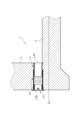
図1に示されるように、床下排水構造10は、建物の基礎コンクリート1の立上部3によって囲まれた空間と基礎コンクリート1の外部とを連通する水抜き配管装置11と、蓋部材12と、を有している。水抜き配管装置11は、立上部3で囲まれた空間に溜まった水を基礎コンクリート1外へ排水するためのものであって、管軸方向の両端開口のうち基礎内に臨む流入口13Aと、この流入口13Aに連通して基礎外に臨む流出口13Bと、を有し、立上部3で囲まれた空間に溜まった基礎内の水が流入口13Aから水抜き配管装置11の内部に流入し、流出口13Bから基礎外に流出されるようになっている。水抜き配管装置11を用いて排水しないときには、流出口13Bを蓋部材12により閉鎖することで、基礎コンクリート1内への水やシロアリ等の害虫や小動物、埃、ごみ等の進入が防止されるようになっている。 As shown in FIG. 1, the underfloor drainage structure 10 includes a drainage piping device 11 that communicates a space surrounded by the rising portion 3 of the basic concrete 1 of the building with the outside of the basic concrete 1, a lid member 12, have. The drain piping device 11 is for draining the water accumulated in the space surrounded by the upright portion 3 to the outside of the foundation concrete 1, and includes an inflow port 13A facing the foundation among openings at both ends in the pipe axial direction. , and an outflow port 13B that communicates with the inflow port 13A and faces the outside of the foundation. It flows in and flows out of the foundation from the outflow port 13B. When water is not drained using the drain piping device 11, the outflow port 13B is closed by the cover member 12, thereby preventing entry of water, pests such as termites, small animals, dust, garbage, etc. into the foundation concrete 1. It's like

図2~図4に示されるように、水抜き配管装置11は、例えば、ポリ塩化ビニル樹脂材(PVC)等により円筒状に形成される外スリーブ管11A(管体)と、例えば、ポリエチレン樹脂材(PE)等により円筒形状に形成される内スリーブ管11B(管体)と、外スリーブ管11Aの外周面に巻装される防蟻シート11C、11C’と、を有する。 As shown in FIGS. 2 to 4, the drain piping device 11 includes an outer sleeve pipe 11A (pipe body) formed cylindrically from, for example, polyvinyl chloride resin (PVC), and a polyethylene resin material, for example. It has an inner sleeve tube 11B (tubular body) formed in a cylindrical shape from a material (PE) or the like, and anti-termite sheets 11C and 11C' wound around the outer peripheral surface of the outer sleeve tube 11A.

外スリーブ管11Aの管軸方向の長さは所定の長さ寸法L1(例えば、L1=120mm)とされ、内スリーブ管11Bの管軸方向の長さは所定の長さ寸法L2(例えば、L1=120mm)とされている。また、内スリーブ管11Bの外径寸法L7は、外スリーブ管11Aの内径寸法L5よりも短寸とされていることで(L7<L5)、内スリーブ管11Bは外スリーブ管11A内に挿入可能とされており、外スリーブ管11Aに対し内スリーブ管11Bを管軸方向にスライド移動させて重合(重複)する重合寸法L3(重合範囲)を変更することで、水抜き配管装置11の全長寸法、つまり、流入口13Aから流出口13Bまでの排水経路長さ寸法L4を、長さ寸法L1よりも長寸の任意の長さ寸法に段階的に変更可能とされている。 The axial length of the outer sleeve tube 11A is a predetermined length L1 (for example, L1=120 mm), and the axial length of the inner sleeve tube 11B is a predetermined length L2 (for example, L1 = 120 mm). In addition, since the outer diameter dimension L7 of the inner sleeve tube 11B is shorter than the inner diameter dimension L5 of the outer sleeve tube 11A (L7<L5), the inner sleeve tube 11B can be inserted into the outer sleeve tube 11A. By sliding the inner sleeve pipe 11B in the axial direction with respect to the outer sleeve pipe 11A to change the overlapped dimension L3 (overlapping range), the total length of the drain piping device 11 can be changed. In other words, the length L4 of the drainage path from the inlet 13A to the outlet 13B can be changed stepwise to any length longer than the length L1.

外スリーブ管11Aの流出口13B側の端部には、内径寸法及び外径寸法が他の部分よりも長寸の拡径部21が形成されており、該拡径部21側から蓋部材12が挿入可能とされている。また、外スリーブ管11Aの内周面には、管軸に対し直交する円環状の凹溝部22が、流入口13A側の開口端部から所定間隔L20(例えば、L20=10mm)おきに複数(本実施例では10個)形成されている。 At the end of the outer sleeve tube 11A on the outflow port 13B side, an enlarged diameter portion 21 having longer inner and outer diameters than other portions is formed. can be inserted. In addition, on the inner peripheral surface of the outer sleeve tube 11A, a plurality of annular grooves 22 perpendicular to the tube axis are provided at predetermined intervals L20 (for example, L20 = 10 mm) from the opening end on the inlet 13A side. In this embodiment, 10) are formed.

内スリーブ管11Bは、一端側が外スリーブ管11A内に挿入可能とされ、他端側に流入口13Aを有する。内スリーブ管11Bの外周面には、管軸に対し直交する円環状の凸条部32が、流出口13Bと反対側の開口端部から所定間隔L20(例えば、L20=10mm)おきに複数(本実施例では10個)形成されている。凸条部32の外径寸法L8は、外スリーブ管11Aの内径寸法L5よりも若干長寸とされており(L8>L5)、凸条部32が弾性変形することにより外スリーブ管11A内に挿入可能であり、凸条部32が凹溝部22内に嵌入して係止されることで、外スリーブ管11Aに対する内スリーブ管11Bの管軸方向への移動が規制される。 One end of the inner sleeve tube 11B can be inserted into the outer sleeve tube 11A, and the other end of the inner sleeve tube 11B has an inlet 13A. On the outer peripheral surface of the inner sleeve tube 11B, a plurality of (for example, L20 = 10 mm) annular convex streaks 32 perpendicular to the tube axis are provided at predetermined intervals L20 (for example, L20 = 10 mm) from the opening end on the side opposite to the outflow port 13B. In this embodiment, 10) are formed. The outer diameter dimension L8 of the ridge portion 32 is slightly longer than the inner diameter dimension L5 of the outer sleeve tube 11A (L8>L5). It is insertable, and the protrusion 32 is fitted into the recessed groove 22 and locked, thereby restricting the axial movement of the inner sleeve tube 11B with respect to the outer sleeve tube 11A.

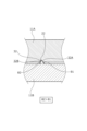
より詳しくは、図5に示されるように、凹溝部22と凸条部32は、管軸方向に沿う縦断面視が略三角形状をなすように形成され、係止部としての凸条部32の先端が被係止部としての凹溝部22内に入り込んで係止されるようになっている。係止状態において、係止力を上回る外力が管軸方向に加えられると、凸条部32の先端が弾性変形して凹溝部22から逸脱して管軸方向にスライド移動可能となる。 More specifically, as shown in FIG. 5, the concave groove portion 22 and the ridge portion 32 are formed to have a substantially triangular shape when viewed in longitudinal section along the pipe axis direction. , the tip of which is inserted into the recessed groove portion 22 as a locked portion to be locked. In the locked state, when an external force exceeding the locking force is applied in the pipe axial direction, the tip of the protruding portion 32 is elastically deformed to deviate from the concave groove portion 22 and become slidable in the pipe axial direction.

また、凸条部32は、流入口13A側の傾斜面32Aと流出口13B側の傾斜面32Bとを有し、傾斜面32Aの下端と傾斜面32Bの下端とを結ぶ管軸に平行な線に対する傾斜面32Bの傾斜角度θ2は、管軸に平行な線に対する傾斜面32Aの傾斜角度θ1よりも大きくなるように形成されている(θ2>θ1)。 The protruding portion 32 has an inclined surface 32A on the side of the inlet 13A and an inclined surface 32B on the side of the outlet 13B. The inclination angle θ2 of the inclined surface 32B with respect to the pipe axis is formed to be larger than the inclination angle θ1 of the inclined surface 32A with respect to a line parallel to the tube axis (θ2>θ1).

つまり、傾斜面32Bの方が傾斜面32Aよりも管軸に対する傾斜角度が大きいため、外スリーブ管11A内に内スリーブ管11Bを押し込む際に傾斜面32Bが凹溝部22の内面に当接するときの係止力の方が、外スリーブ管11Aから内スリーブ管11Bを引き抜く際に傾斜面32Aが凹溝部22の内面に係止されるときの係止力よりも大きくなっている。このような構造により、施工時に、設定した長さよりも短い長さとなってしまうことを防止できる。 That is, since the inclined surface 32B has a larger inclination angle with respect to the tube axis than the inclined surface 32A, the inclined surface 32B contacts the inner surface of the groove 22 when the inner sleeve tube 11B is pushed into the outer sleeve tube 11A. The locking force is larger than the locking force when the inclined surface 32A is locked to the inner surface of the concave groove portion 22 when the inner sleeve tube 11B is pulled out from the outer sleeve tube 11A. With such a structure, it is possible to prevent the length from becoming shorter than the set length during construction.

尚、本実施例では、内スリーブ管11Bの外周面に形成された複数の凸条部32と、外スリーブ管11Aの内周面に形成された複数の凹溝部22とからなる複数の係止手段のうち、同時に係止状態となる係止手段の個数を変更することで重合寸法L3を変更可能な形態を例示したが、本発明はこれに限定されるものではなく、外スリーブ管11Aの内周面に形成された複数の凹溝部22のいずれかに、内スリーブ管11Bの外周面に形成された1個の凸条部32を係止させることで重合寸法L3を変更可能、または、外スリーブ管11Aの内周面に形成された1個の凹溝部22に、内スリーブ管11Bの外周面に形成された複数の凸条部32のうちいずれかを係止させることで重合寸法L3を変更可能としてもよい。 In addition, in this embodiment, a plurality of engaging portions are formed by a plurality of ridges 32 formed on the outer peripheral surface of the inner sleeve tube 11B and a plurality of recessed grooves 22 formed on the inner peripheral surface of the outer sleeve tube 11A. Although the form in which the overlapping dimension L3 can be changed by changing the number of locking means that are in the locking state at the same time among the means has been exemplified, the present invention is not limited to this, and the outer sleeve tube 11A The overlapping dimension L3 can be changed by engaging one of the ridges 32 formed on the outer peripheral surface of the inner sleeve tube 11B with one of the plurality of grooves 22 formed on the inner peripheral surface, or By engaging one of the plurality of ridges 32 formed on the outer peripheral surface of the inner sleeve tube 11B with one concave groove 22 formed on the inner peripheral surface of the outer sleeve tube 11A, the overlapping length L3 is obtained. may be changeable.

また、内スリーブ管11Bの流出口13B側の端部にシール部材を設け、外スリーブ管11Aの内周面に対して密着するようにするようにしてもよく、このようにすることで、基礎の施工後に外スリーブ管11Aと内スリーブ管11Bの隙間からコンクリート内に水がしみ出ることを防止できる。 A seal member may be provided at the end of the inner sleeve tube 11B on the outflow port 13B side so as to be in close contact with the inner peripheral surface of the outer sleeve tube 11A. It is possible to prevent water from seeping into the concrete from the gap between the outer sleeve pipe 11A and the inner sleeve pipe 11B after the construction of .

また、内スリーブ管11Bの外周面における流入口13A側の端部には、外側に突出する指掛け部としてのフランジ部33が形成されている。フランジ部33の外径寸法L9は、外スリーブ管11Aの外径寸法L6よりも長寸とされているため(L9>L6)、フランジ部33が外スリーブ管11Aの端部に近づいたときでも、フランジ部33が外スリーブ管11Aの外周面より外方に突出するため、フランジ部33に容易に指を掛けることができる。 In addition, a flange portion 33 as a finger hook portion protruding outward is formed at the end portion on the inlet 13A side of the outer peripheral surface of the inner sleeve tube 11B. Since the outer diameter dimension L9 of the flange portion 33 is longer than the outer diameter dimension L6 of the outer sleeve pipe 11A (L9>L6), even when the flange portion 33 approaches the end of the outer sleeve pipe 11A, Since the flange portion 33 protrudes outward from the outer peripheral surface of the outer sleeve tube 11A, a finger can be easily put on the flange portion 33. As shown in FIG.

尚、本実施例では、指掛け部の一例として、内スリーブ管11Bの外周面に環状に形成されたフランジ部33を適用した形態を例示したが、本発明はこれに限定されるものではなく、内スリーブ管11Bの周方向の一部にのみ指掛け部が形成されていてもよい。また、指掛け部は端部でなく端部近傍に形成されていてもよい。 In this embodiment, as an example of the finger hooking portion, the form in which the annular flange portion 33 is applied to the outer peripheral surface of the inner sleeve tube 11B is exemplified, but the present invention is not limited to this. A finger hook portion may be formed only on a part of the inner sleeve tube 11B in the circumferential direction. Also, the finger hook may be formed near the end instead of the end.

防蟻シート11C、11C’は、弾性部材または非加硫部材に防蟻剤を含有させたものを、所定厚み寸法(例えば、2~5mm)のシート状物として形成したものであり、例えば、ブチル再生ゴムが挙げられ、ブチル再生ゴム単独、またはブチル再生ゴムに天然ゴム、合成ゴム、熱可塑性エラストマー等を一種以上混合したものであってもよい。また、弾性部材または非加硫部材に補強剤、充填剤、可塑剤、軟化剤、老化防止剤、粘着剤、加工助剤、着色剤、架橋剤、架橋助剤等を適宜配合しても良い。 The anti-termite sheets 11C and 11C' are formed as sheets having a predetermined thickness (for example, 2 to 5 mm) by incorporating an anti-termite agent into an elastic member or a non-vulcanized member. Recycled butyl rubber may be mentioned, and regenerated butyl rubber may be used alone, or regenerated butyl rubber may be mixed with one or more kinds of natural rubber, synthetic rubber, thermoplastic elastomer, and the like. In addition, reinforcing agents, fillers, plasticizers, softeners, anti-aging agents, pressure-sensitive adhesives, processing aids, coloring agents, cross-linking agents, cross-linking aids, etc. may be appropriately blended into the elastic member or the unvulcanized member. .

また、第1部材としての防蟻シート11C’は、第2部材としての防蟻シート11Cよりも硬度が高く、流出口13B側の端部(外部側端部)に設けられ、防蟻シート11Cは、防蟻シート11C’よりも流入口13A側(内部側)に設けられている。尚、本実施例では、流出口13B側の端部に設けられる防蟻シート11C’の方が流入口13A側の防蟻シート11Cよりも硬度が高い形態を例示したが、本発明はこれに限定されるものではなく、防蟻シート11C、11C’の硬度は同一または略同一でもよい。また、防蟻シート11C、11C’は別個に形成されていてもよいし、2色成形等により一体に形成されていてもよい。さらに、少なくとも外スリーブ管11Aの外周面における流出口13B側の端部(外部側端部)または流出口13B側の端部近傍(外部側端部近傍)に設けられていれば、他の部分は設けられていなくてもよい。 In addition, the termite-proof sheet 11C′ as the first member has higher hardness than the termite-proof sheet 11C as the second member, and is provided at the end on the outflow port 13B side (outside end). is provided on the inlet 13A side (inner side) of the anti-termite sheet 11C'. In this embodiment, the termite-preventing sheet 11C′ provided at the end on the outflow port 13B side has a higher hardness than the termite-preventing sheet 11C on the inflow port 13A side, but the present invention is not limited to this. The hardness of the anti-termite sheets 11C and 11C' may be the same or substantially the same. Also, the anti-termite sheets 11C and 11C' may be formed separately, or may be integrally formed by two-color molding or the like. Further, if provided at least at the end on the outflow port 13B side (external end) or near the end on the outflow port 13B side (near the external end) on the outer peripheral surface of the outer sleeve tube 11A, other portions may not be provided.

蓋部材12は、外径寸法L10が外スリーブ管11Aの拡径部21の内径寸法L5’よりも短寸(L10<L5’)の筒状部40と、筒状部40の一端開口を閉鎖するように設けられる円盤状の蓋板41と、から構成される。筒状部40の外周面には、外スリーブ管11Aの拡径部21内に挿入可能、かつ、拡径部21より奥側に挿入不可な環状のガイド部42が突設されており、該ガイド部42の外周面に形成された凹溝内には、ゴム材等からなるシール部材43が嵌装されている。 The lid member 12 closes the tubular portion 40 having an outer diameter L10 smaller than the inner diameter L5′ (L10<L5′) of the enlarged diameter portion 21 of the outer sleeve tube 11A, and an opening at one end of the tubular portion 40. and a disk-shaped cover plate 41 provided to do so. An annular guide portion 42, which can be inserted into the enlarged diameter portion 21 of the outer sleeve tube 11A and cannot be inserted deeper than the enlarged diameter portion 21, protrudes from the outer peripheral surface of the cylindrical portion 40. A seal member 43 made of a rubber material or the like is fitted in a concave groove formed on the outer peripheral surface of the guide portion 42 .

よって、外スリーブ管11Aの流出口13Bに筒状部40が挿入され、ガイド部42が拡径部21内に位置すると、シール部材43が拡径部21の内周面に圧接されることで、流出口13Bが蓋部材12により水封状態で閉鎖される。 Therefore, when the cylindrical portion 40 is inserted into the outflow port 13B of the outer sleeve tube 11A and the guide portion 42 is positioned within the enlarged diameter portion 21, the sealing member 43 is pressed against the inner peripheral surface of the enlarged diameter portion 21. , the outflow port 13B is closed by the cover member 12 in a water-sealed state.

また、蓋板41の外径寸法L11は、外スリーブ管11Aの拡径部21の外径寸法L6’よりも長寸とされていることで(L11>L6’)、蓋板41が外スリーブ管11Aの流出口13Bの周囲の端面に当接して流出口13Bが閉鎖されたときに、蓋板41の鍔部41Aが外スリーブ管11Aの外周面よりも外側に突出するように配置される。また、蓋板41の外周縁部には、中心側から外側にかけて肉薄となるように流出口13B側に傾斜する傾斜面41Bが形成されている。 In addition, since the outer diameter dimension L11 of the cover plate 41 is longer than the outer diameter dimension L6′ of the enlarged diameter portion 21 of the outer sleeve tube 11A (L11>L6′), the cover plate 41 becomes the outer sleeve. The flange 41A of the cover plate 41 is arranged to protrude outward from the outer peripheral surface of the outer sleeve tube 11A when the outlet 13B is closed by contacting the end surface of the tube 11A around the outlet 13B. . In addition, an inclined surface 41B is formed on the outer peripheral edge of the cover plate 41 and is inclined toward the outflow port 13B so as to become thinner from the center to the outside.

蓋板41の外面略中央位置には、矩形状の開口を有する凹部44が形成されており、該凹部44内にドライバー等の工具等を嵌入し、蓋部材12を管軸方向に引きぬくことで、蓋部材12を外スリーブ管11Aから取り外すことができるようになっている。 A recessed portion 44 having a rectangular opening is formed at approximately the center of the outer surface of the lid plate 41. A tool such as a screwdriver is inserted into the recessed portion 44 to pull out the lid member 12 in the direction of the tube axis. , the cover member 12 can be removed from the outer sleeve tube 11A.

なお、蓋部材12は外スリーブ管11A内に挿入されることで取り付けられる構造であるが、後述する実施例2のように蓋部材12が外スリーブ管11A内に螺合して取り付けられる構造であってもよい。 The cover member 12 is attached by being inserted into the outer sleeve tube 11A. However, as in a second embodiment described later, the cover member 12 is attached by being screwed into the outer sleeve tube 11A. There may be.

このように構成された水抜き配管装置11は、図6(a)、(b)に示されるように、内スリーブ管11Bを、外スリーブ管11Aにおける流出口13Bと反対側の開口から挿入可能であり、外スリーブ管11Aに対し内スリーブ管11Bを管軸方向にスライド移動させて重合(重複)する重合寸法L3を変更することで、水抜き配管装置11の全長寸法、つまり、流入口13Aから流出口13Bまでの排水経路長さ寸法L4を、長さ寸法L1よりも長寸の任意の長さ寸法に変更可能とされている。 As shown in FIGS. 6(a) and 6(b), the drainage piping device 11 configured in this manner allows the inner sleeve pipe 11B to be inserted through the opening of the outer sleeve pipe 11A on the side opposite to the outflow port 13B. By changing the overlapping dimension L3 that overlaps (overlaps) by sliding the inner sleeve pipe 11B with respect to the outer sleeve pipe 11A in the pipe axial direction, the overall length of the drain piping device 11, that is, the inlet port 13A to the outflow port 13B can be changed to any length dimension longer than the length dimension L1.

具体的には、図6(a)に示されるように、内スリーブ管11Bのほぼ全域が外スリーブ管11A内に挿入された場合、重合寸法L3が長寸となるため、排水経路長さ寸法L4は短寸となる。一方、図6(b)に示されるように、内スリーブ管11Bの一部が外スリーブ管11A内に挿入された場合、重合寸法L3が短寸となるため、排水経路長さ寸法L4は長寸となる。よって、立上部3の厚さ寸法に合わせて排水経路長さ寸法L4を変更することができる。 Specifically, as shown in FIG. 6(a), when almost the entire inner sleeve tube 11B is inserted into the outer sleeve tube 11A, the overlapping dimension L3 becomes long, so the length dimension of the drainage path is L4 is short. On the other hand, as shown in FIG. 6(b), when a part of the inner sleeve tube 11B is inserted into the outer sleeve tube 11A, the overlapping dimension L3 becomes short, so the drainage path length dimension L4 becomes long. dimension. Therefore, the drainage path length dimension L4 can be changed according to the thickness dimension of the rising portion 3 .

また、外スリーブ管11Aに対し内スリーブ管11Bを管軸方向にスライド移動させるときに、凸条部32が凹溝部22内に嵌入して係止されることで、所望の排水経路長さ寸法L4に変更した後、接着剤やねじ部材等を用いて外スリーブ管11Aに対する内スリーブ管11Bの管軸方向への移動を規制しなくても、所望の排水経路長さ寸法L4に維持されるため、外スリーブ管11Aに対する内スリーブ管11Bの位置ずれが防止でされる。尚、係止状態において管軸方向に係止力よりも大きい外力を加えることで係止状態が解除されるため、長さの変更を容易に行うことができる。 Further, when the inner sleeve tube 11B is slid in the tube axial direction with respect to the outer sleeve tube 11A, the ridges 32 are fitted into the grooves 22 and locked, so that the desired length of the drainage path can be achieved. After changing to L4, the desired drainage path length dimension L4 is maintained without restricting the axial movement of the inner sleeve tube 11B with respect to the outer sleeve tube 11A using an adhesive, a screw member, or the like. Therefore, displacement of the inner sleeve tube 11B with respect to the outer sleeve tube 11A is prevented. In addition, since the locked state is released by applying an external force larger than the locking force in the tube axial direction in the locked state, the length can be easily changed.

本実施例では、外スリーブ管11Aの長さ寸法が120mm、外スリーブ管11Aの凹溝部22及び内スリーブ管11Bの凸条部32がそれぞれ10mmおきに10個形成された例を示しており、排水経路長さ寸法L4を120~220mm(+フランジ33の厚み)の範囲で変更可能であるが、凹溝部22及び凸条部32の間隔を10mm以外の間隔(例えば、1mm、2mm、5mm、15mm等)としても良く、凹溝部22及び凸条部32の数を10個以外の数(例えば、2個、5個、15個等)としても良い。また、排水経路長さ寸法L4を変更可能な範囲についても120~220mm(+フランジ33の厚み)に限らず、外スリーブ管11Aや内スリーブ管11Bの長さを異なる長さとすることで、それ以外の範囲に変更可能としても良い。 This embodiment shows an example in which the length dimension of the outer sleeve tube 11A is 120 mm, and ten recessed groove portions 22 of the outer sleeve tube 11A and ten protruded streak portions 32 of the inner sleeve tube 11B are formed at intervals of 10 mm. The drainage path length dimension L4 can be changed in the range of 120 to 220 mm (+ the thickness of the flange 33), but the interval between the concave groove portion 22 and the convex ridge portion 32 can be changed to an interval other than 10 mm (for example, 1 mm, 2 mm, 5 mm, 15 mm, etc.), and the number of the groove portions 22 and the protrusion portions 32 may be set to a number other than ten (for example, two, five, fifteen, etc.). Also, the range in which the length L4 of the drainage path can be changed is not limited to 120 to 220 mm (+the thickness of the flange 33), and by making the lengths of the outer sleeve tube 11A and the inner sleeve tube 11B different, It may be possible to change to a range other than the above.

[水抜き配管装置11を用いた床下排水構造10の施工例]
次に、水抜き配管装置11を用いた床下排水構造10の施工例について、図7及び図8に基づいて説明する。
[Construction Example of Underfloor Drainage Structure 10 Using Drain Piping Device 11]
Next, a construction example of the underfloor drainage structure 10 using the drain piping device 11 will be described with reference to FIGS. 7 and 8. FIG.

まず、図7(a)に示されるように、底盤コンクリート部2と立上部3とを構成するためのコンクリートが打設される部分に鉄筋(図示略)を配設する。また、立上部3の外面を構成するための外側の型枠FAを設置しておく。また、使用する水抜き配管装置11については、前述したように、外スリーブ管11Aに対し内スリーブ管11Bを管軸方向にスライド移動させて重合(重複)する重合寸法L3を変更することで、施工する立上部3の厚み寸法に応じた排水経路長さ寸法L4に予め設定しておく。尚、蓋部材12は外スリーブ管11Aから取り外しておく。 First, as shown in FIG. 7(a), reinforcing bars (not shown) are placed in the portions where the concrete for forming the base concrete portion 2 and the rising portion 3 is placed. In addition, an outer formwork FA for forming the outer surface of the upright portion 3 is installed. In addition, as described above, regarding the water drain piping device 11 to be used, by sliding the inner sleeve pipe 11B in the pipe axial direction with respect to the outer sleeve pipe 11A and changing the overlapping dimension L3 to overlap (overlap), The drainage path length dimension L4 is set in advance according to the thickness dimension of the rising portion 3 to be constructed. Incidentally, the cover member 12 is removed from the outer sleeve tube 11A.

次いで、図7(b)に示されるように、底盤コンクリート部2を打設する。底盤コンクリート部2が硬化状態となる前に、水抜き配管装置11を載置する。例えば、水抜き配管装置11を底盤コンクリート部2に押しつけることにより、水抜き配管装置11の下側部分を底盤コンクリート部2に埋め込むように設置することができる。水抜き配管装置11の下面を硬化前の底盤コンクリート部2に押しつけることにより、水抜き配管装置11の下面と底盤コンクリート部2との間の空気を好適に抜くことができる。 Next, as shown in FIG. 7(b), the bottom slab concrete portion 2 is placed. The drainage piping device 11 is placed before the bottom concrete portion 2 is hardened. For example, by pressing the drainage piping device 11 against the bottom concrete portion 2 , the bottom portion of the drainage piping device 11 can be installed so as to be embedded in the bottom concrete portion 2 . By pressing the lower surface of the drainage piping device 11 against the bottom concrete portion 2 before hardening, the air between the bottom surface of the drainage piping device 11 and the bottom concrete portion 2 can be preferably removed.

また、水抜き配管装置11の下面を硬化前の底盤コンクリート部2に押しつける際に、内スリーブ管11Bの流入口13Aの下端を、底盤コンクリート部2の上面と同高さまたはやや下方に配置することで、底盤コンクリート部2の上面にたまる水が流入口13Aに流入しやすくなる。また、外スリーブ管11Aの流出口13B側の端面を外側の型枠FAの内面に押し付けるように当接させて、型枠FAの内面と端面との間からコンクリートが進入しないようにする。なお、ここで流入口13Aに水を流入し易くするための集水路や誘導路を別途設置、もしくは、コンクリート面上に形成するようにしてもよい。 Also, when pressing the lower surface of the drainage piping device 11 against the unhardened base concrete portion 2, the lower end of the inlet 13A of the inner sleeve pipe 11B is positioned at the same height as or slightly below the upper surface of the base concrete portion 2. This makes it easier for the water accumulated on the upper surface of the bottom concrete portion 2 to flow into the inlet 13A. In addition, the end face of the outer sleeve pipe 11A on the outflow port 13B side is pressed against the inner surface of the outer formwork FA to prevent concrete from entering between the inner surface and the end face of the formwork FA. In addition, a collection channel or guideway may be installed separately or formed on the concrete surface for facilitating the flow of water into the inlet 13A.

また、水抜き配管装置11は、凸条部32の傾斜面32Bの傾斜角度θ2の方が、傾斜面32Aの傾斜角度θ1よりも大きいことで(θ2>θ1)、重合寸法L3を長寸とするスライド方向への係止力が、重合寸法L3を短寸とするスライド方向への係止力よりも大きい、つまり、内スリーブ管11Bの挿入方向へのスライド移動を規制する係止力の方が、抜脱方向へのスライド移動を規制する係止力よりも大きいため、水抜き配管装置11を硬化前の底盤コンクリート部2に配置してからコンクリートが硬化するまでの間に、例えば、型枠FBを設置するときに接触するなどの外力が加わるなどして、設定した長さよりも短い長さとなってしまうことを防止できる。 In addition, in the drainage piping device 11, the inclination angle θ2 of the inclined surface 32B of the protruding portion 32 is larger than the inclination angle θ1 of the inclined surface 32A (θ2>θ1), so that the overlapping length L3 is set as the long dimension. The locking force in the sliding direction is greater than the locking force in the sliding direction that makes the overlapping dimension L3 short. However, since it is larger than the locking force that restricts the slide movement in the removal direction, after the drainage piping device 11 is arranged on the base concrete portion 2 before hardening and before the concrete hardens, for example, the mold It is possible to prevent the length from becoming shorter than the set length due to external force such as contact when installing the frame FB.

また、内スリーブ管11Bのフランジ部33の下部がコンクリートに埋め込まれるように設置されるので、底盤コンクリート部2のコンクリートが硬化した後、立上部3のコンクリートが打設されるときに、流れ込むコンクリートに押されるなどして、内スリーブ管11Bが管軸方向に位置ずれすることが防止される。 Further, since the lower portion of the flange portion 33 of the inner sleeve pipe 11B is installed so as to be embedded in the concrete, when the concrete of the base concrete portion 2 hardens and the concrete of the rising portion 3 is placed, the concrete that flows into Thus, the inner sleeve tube 11B is prevented from being displaced in the tube axial direction due to being pushed by the inner sleeve tube 11B.

尚、特に図示しないが、外スリーブ管11Aの外周面下部における管軸の両側方に、底盤コンクリート部2の上面に固定するための一対の座部を突設したり、あるいは、外スリーブ管11Aの外周面下部に底盤コンクリート部2内に埋設される杭部を突設することで、水抜き配管装置11が周方向に転がることを防止するようにしてもよい。更に、前記した一対の座部における外スリーブ管11Aの載置面を僅かに傾斜して形成してもよく、このようにすることで、水抜き配管装置11を立上部3の内部から外部に向けて下方に傾斜させ易く、排水を促進させることができる。 Although not particularly shown, a pair of seat portions for fixing to the upper surface of the base concrete portion 2 may protrude from both sides of the pipe axis at the lower portion of the outer peripheral surface of the outer sleeve pipe 11A. By protruding a pile portion embedded in the bottom plate concrete portion 2 at the lower part of the outer peripheral surface of the drain piping device 11, the drain piping device 11 may be prevented from rolling in the circumferential direction. Furthermore, the mounting surfaces of the outer sleeve pipe 11A on the pair of seat portions may be formed to be slightly inclined. It is easy to incline downward toward the bottom, and drainage can be promoted.

次いで、図7(c)に示されるように、内側の型枠FBを設置する。このとき、内側の型枠FBの内面を、内スリーブ管11Bの流入口13A側の端面に押し付けるように当接させて、型枠FBの内面と端面との間からコンクリートが進入しないようにする。これにより水抜き配管装置11は管軸の両側から型枠FA、FBによって挟まれた状態になる。尚、フランジ部33の型枠FBとの当接面に、コンクリートの進入を防止するためのOリング等を設けてもよい。その後、立上部3のコンクリートを打設する。 Next, as shown in FIG. 7(c), the inner formwork FB is installed. At this time, the inner surface of the inner formwork FB is brought into contact with the end surface of the inner sleeve pipe 11B on the side of the inlet 13A so as to be pressed so that the concrete does not enter from between the inner surface and the end surface of the formwork FB. . As a result, the drain piping device 11 is sandwiched between the forms FA and FB from both sides of the pipe axis. An O-ring or the like for preventing concrete from entering may be provided on the contact surface of the flange portion 33 with the formwork FB. After that, concrete for the rising portion 3 is placed.

そして、立上部3のコンクリートが硬化した後、型枠FA、FBを撤去すると、水抜き配管装置11が立上部3を厚み方向に貫通するように配設された床下排水構造10が構成される。 After the concrete of the rising portion 3 has hardened, the formwork FA and FB are removed to form the underfloor drainage structure 10 in which the drainage piping device 11 is disposed so as to penetrate the rising portion 3 in the thickness direction. .

床下排水構造10が構成された状態において、立上部3の内面に対し流入口13Aが略面一に配置され、立上部3の外面に対し流出口13Bが略面一に配置される。また、流入口13Aの下端が底盤コンクリート部2の上面と同高さまたはやや下方に配置されることで、底盤コンクリート部2の上面に溜まる水が流入口13Aに流入しやすくなる。 When the underfloor drainage structure 10 is configured, the inlet 13A is arranged substantially flush with the inner surface of the rising portion 3, and the outlet 13B is arranged substantially flush with the outer surface of the rising portion 3. In addition, by arranging the lower end of the inlet 13A at the same height as or slightly below the upper surface of the base concrete portion 2, the water accumulated on the upper surface of the base concrete portion 2 easily flows into the inlet 13A.

流入口13Aから内部に流入された水は、水抜き配管装置11内を流出口13B側に向けて誘導された後、流出口13Bから基礎外へ流出される。また、外スリーブ管11Aの内部に内スリーブ管11Bが重合するように挿入されることで、内スリーブ管11Bの内周面下部の方が外スリーブ管11Aの内周面下部よりも高くなるので、流入口13Aから内部に流入された水は内スリーブ管11Bから外スリーブ管11Aにスムーズに誘導される。尚、内スリーブ管11Bの内部に外スリーブ管11Aが挿入されるように外スリーブ管11Aと内スリーブ管11Bとを重合させてもよい。 The water that has flowed into the interior from the inflow port 13A is guided through the drain piping device 11 toward the outflow port 13B, and then flows out of the foundation from the outflow port 13B. In addition, since the inner sleeve tube 11B is inserted into the outer sleeve tube 11A so as to overlap, the lower portion of the inner peripheral surface of the inner sleeve tube 11B is higher than the lower portion of the inner peripheral surface of the outer sleeve tube 11A. , the water flowing inside from the inlet 13A is smoothly guided from the inner sleeve pipe 11B to the outer sleeve pipe 11A. The outer sleeve tube 11A and the inner sleeve tube 11B may be overlapped so that the outer sleeve tube 11A is inserted inside the inner sleeve tube 11B.

また、外スリーブ管11Aの外周面に防蟻剤を含有する防蟻シート11C、11C’が配置されることで、コンクリートと外スリーブ管11Aとの間に隙間が生じることがなく、隙間からのシロアリ等の害虫、埃、ごみ等の侵入を防止できるとともに、シロアリに対する防蟻効果が高められる。 In addition, since the anti-termite sheets 11C and 11C' containing the anti-termite agent are arranged on the outer peripheral surface of the outer sleeve pipe 11A, there is no gap between the concrete and the outer sleeve pipe 11A, and the Intrusion of pests such as termites, dust, garbage, etc. can be prevented, and the anti-termite effect against termites can be enhanced.

また、防蟻シート11C’は、外スリーブ管11Aの外周面のうち少なくとも流出口13B側の端部を被覆するように設けられることで、シロアリの侵入を効果的に防止できる。また、防蟻シート11C’の方が防蟻シート11Cよりも硬度が高いため、防蟻シート11C’の流出を防止できる一方、防蟻シート11C’よりも流入口13A側に相対的に硬度の低い防蟻シート11Cが設けられることで、コンクリートと外スリーブ管11Aの外周面との間に隙間が生じることを確実に防止できる。 Also, the termite-proof sheet 11C' is provided so as to cover at least the end portion of the outer peripheral surface of the outer sleeve tube 11A on the outflow port 13B side, thereby effectively preventing entry of termites. Further, since the anti-termite sheet 11C' is harder than the anti-termite sheet 11C, it is possible to prevent the outflow of the anti-termite sheet 11C'. By providing the low anti-termite sheet 11C, it is possible to reliably prevent the formation of a gap between the concrete and the outer peripheral surface of the outer sleeve pipe 11A.

図8(a)に示されるように、内スリーブ管11Bにおいて凹溝部22に係止されていない凸条部32が外周面に露呈されることで、コンクリートの硬化後における内スリーブ管11Bの立上部3からの抜脱が好適に規制される。 As shown in FIG. 8( a ), the ridges 32 of the inner sleeve pipe 11B that are not engaged with the concave grooves 22 are exposed on the outer peripheral surface, so that the inner sleeve pipe 11B stands upright after the concrete hardens. Detachment from the upper part 3 is preferably restricted.

また、図8(a)に示されるように、立上部3のコンクリートの硬化後に、流出口13Bに蓋部材12を取り付けることで、流出口13Bからのシロアリの侵入を防止できる。蓋部材12が取り付けられた状態において、蓋板41の鍔部41Aが、流出口13Bの周囲の外スリーブ管11Aの端面のさらに外側に拡がるコンクリートの表面に重なることで、流出口13Bの周囲の外スリーブ管11Aの端面とコンクリートの表面との境界部が隠蔽されるため、意匠性が向上する。 In addition, as shown in FIG. 8A, after the concrete of the rising portion 3 has hardened, the cover member 12 is attached to the outflow port 13B to prevent termites from entering through the outflow port 13B. When the cover member 12 is attached, the flange portion 41A of the cover plate 41 overlaps the surface of the concrete extending further outward from the end face of the outer sleeve tube 11A around the outflow port 13B. Since the boundary between the end face of the outer sleeve pipe 11A and the concrete surface is concealed, the design is improved.

また、蓋板41の外周縁部には、中心側から外側にかけて肉薄となるように流出口13B側に傾斜する傾斜面41Bが形成されているため、蓋部材12とコンクリート表面との境界部が目立ち難く、蓋部材12にて流出口13Bを閉鎖した際の意匠性が向上する。 In addition, since an inclined surface 41B inclined toward the outflow port 13B side is formed on the outer peripheral edge of the cover plate 41 so as to become thin from the center side to the outside, the boundary portion between the cover member 12 and the concrete surface is formed. This is inconspicuous, and the design when the outlet 13B is closed with the lid member 12 is improved.

また、図8(b)に示されるように、立上部3のコンクリートの硬化後、底盤コンクリート部2及び立上部3の外面(表面)に、モルタル等を塗布するなどの化粧処理を施すことにより塗膜部5が設けられることがある。 Further, as shown in FIG. 8(b), after the concrete of the rising portion 3 has hardened, the outer surfaces (surfaces) of the base concrete portion 2 and the rising portion 3 are subjected to decorative treatment such as applying mortar or the like. A coating film portion 5 may be provided.

また、この場合、蓋部材12の蓋板41は塗膜部5の表面側に配置されることで、蓋板41が外スリーブ管11Aの端面から離れることになるが、シール部材43は拡径部21の内周面に当接されるため、流出口13Bの水封状態は維持される。 In this case, the cover plate 41 of the cover member 12 is arranged on the surface side of the coating film portion 5, so that the cover plate 41 is separated from the end surface of the outer sleeve tube 11A. Since it abuts against the inner peripheral surface of the portion 21, the water-sealed state of the outflow port 13B is maintained.

また、本実施例では、外スリーブ管11Aと内スリーブ管11Bとの重合範囲を変更することで排水経路長さ寸法L4を変更可能な形態を例示したが、本発明はこれに限定されるものではなく、3本以上の管体を互いに重合させて排水経路長さ寸法L4を変更可能としてもよい。 Further, in this embodiment, the configuration in which the length L4 of the drainage path can be changed by changing the overlapping range of the outer sleeve tube 11A and the inner sleeve tube 11B was exemplified, but the present invention is limited to this. Instead, three or more tubular bodies may be overlapped with each other to change the length L4 of the drainage path.

また、本実施例では、外スリーブ管11Aの一端に流出口が形成され、内スリーブ管11Bの他端に流入口が形成される構成であるが、外スリーブ管11Aの一端に流入口が形成され、内スリーブ管11Bの他端に流出口が形成される構成としても良い。 In this embodiment, the outlet is formed at one end of the outer sleeve tube 11A and the inlet is formed at the other end of the inner sleeve tube 11B, but the inlet is formed at one end of the outer sleeve tube 11A. and an outflow port may be formed at the other end of the inner sleeve tube 11B.

[変形例1]
次に、本発明の変形例1としての水抜き配管装置11について、図9に基づいて説明する。図9は、本発明の変形例1としての水抜き配管装置の内部構造を示す縦断面図である。
[Modification 1]
Next, a drain piping device 11 as Modification 1 of the present invention will be described with reference to FIG. FIG. 9 is a vertical cross-sectional view showing the internal structure of a drain piping device as Modification 1 of the present invention.

実施例1では、内スリーブ管11Bの外周面に形成された係止部としての凸条部32を、外スリーブ管11Aの内周面に形成された凹溝部22に係止させることで、外スリーブ管11Aに対して内スリーブ管11Bを管軸方向へスライド移動可能にするとともに、外スリーブ管11Aに対する内スリーブ管11Bの管軸方向へのスライド移動が規制される形態を例示した。しかしながら、本発明はこれに限定されるものではなく、例えば、図9に示されるように、外スリーブ管11Aの内周面に雌ねじ部25を螺旋状に形成するとともに、内スリーブ管11Bの外周面に雄ねじ部35を螺旋状に形成し、内スリーブ管11Bを管軸周りに回転させて雌ねじ部25に雄ねじ部35を螺入させるようにしてもよい。このようにすることで、外スリーブ管11Aに対して内スリーブ管11Bを管軸方向へスライド移動可能にするとともに、外スリーブ管11Aに対する内スリーブ管11Bの管軸方向へのスライド移動が規制される。 In the first embodiment, the outer sleeve tube 11B has a protruding portion 32 formed on the outer peripheral surface of the inner sleeve tube 11B as a locking portion and engaged with a concave groove portion 22 formed on the inner peripheral surface of the outer sleeve tube 11A. A configuration is illustrated in which the inner sleeve tube 11B is slidable in the tube axial direction with respect to the sleeve tube 11A and the axial slide movement of the inner sleeve tube 11B with respect to the outer sleeve tube 11A is restricted. However, the present invention is not limited to this. For example, as shown in FIG. The male threaded portion 35 may be spirally formed on the surface, and the male threaded portion 35 may be screwed into the female threaded portion 25 by rotating the inner sleeve tube 11B around the tube axis. By doing so, the inner sleeve tube 11B can be slid in the tube axial direction relative to the outer sleeve tube 11A, and the axial slide movement of the inner sleeve tube 11B relative to the outer sleeve tube 11A is restricted. be.

この場合、内スリーブ管11Bを管軸周りに正回転または逆回転させることで重合寸法L3(重合範囲)を変更することで、水抜き配管装置11の全長寸法L4を、長さ寸法L1よりも長寸の長さ寸法に無段階に変更可能とされている。この際、内スリーブ管11Bを管軸周りに回転させるだけの簡単な作業で長さを変更し、かつ変更後の長さ寸法を維持することができる。尚、外スリーブ管11Aの内周面に螺旋状の雄ねじ部を形成するとともに、内スリーブ管11Bの外周面に螺旋状の雌ねじ部を形成してもよい。 In this case, by rotating the inner sleeve pipe 11B forward or backward about the pipe axis to change the overlapping dimension L3 (overlapping range), the total length dimension L4 of the water draining piping device 11 is made larger than the length dimension L1. The length dimension can be changed steplessly. At this time, the length can be changed by a simple operation of rotating the inner sleeve tube 11B around the tube axis, and the length dimension after the change can be maintained. A helical male thread may be formed on the inner peripheral surface of the outer sleeve tube 11A, and a helical female thread may be formed on the outer peripheral surface of the inner sleeve tube 11B.

また、特に図示しないが、外スリーブ管11Aの内周面に対して内スリーブ管11Bの外周面が接触した状態で管軸方向へスライド移動可能にするようにしてもよい。このような構成では、内スリーブ管11Bの流出口13B側の端部にシール部材を設け、外スリーブ管11Aの内周面に対して密着するようにしてもよく、このようにすることで、基礎の施工後に外スリーブ管11Aと内スリーブ管11Bの隙間からコンクリート内に水がしみ出ることを防止できる。 Moreover, although not shown, the inner sleeve tube 11B may be slidably moved in the tube axial direction while the outer peripheral surface of the inner sleeve tube 11B is in contact with the inner peripheral surface of the outer sleeve tube 11A. In such a configuration, a seal member may be provided at the end of the inner sleeve tube 11B on the outflow port 13B side so as to be in close contact with the inner peripheral surface of the outer sleeve tube 11A. It is possible to prevent water from seeping into the concrete from the gap between the outer sleeve pipe 11A and the inner sleeve pipe 11B after the construction of the foundation.

本発明の実施例2としての水抜き配管装置について、図10~図13を参照して説明する。図10は、本発明の実施例2としての水抜き配管装置の構成を示す分解斜視図である。図11は、図10の水抜き配管装置の内部構造を示す断面図である。図12は、(a)~(c)は排水経路長さ寸法を変更する一例を示す断面図である。図13は、(a)は蓋部材が外スリーブ管に取り付けられた状態、(b)は化粧処理後に蓋部材が外スリーブ管に取り付けられた状態を示す断面図である。尚、以下の説明において、前記実施例1と同様の部材や部位については、同様の符号を付すことにより詳細な説明を省略する。 A drain piping device as a second embodiment of the present invention will be described with reference to FIGS. 10 to 13. FIG. FIG. 10 is an exploded perspective view showing the configuration of a drain piping device as Embodiment 2 of the present invention. 11 is a cross-sectional view showing the internal structure of the drain piping device of FIG. 10. FIG. 12A to 12C are cross-sectional views showing an example of changing the length dimension of the drainage path. 13(a) is a cross-sectional view showing a state in which the lid member is attached to the outer sleeve tube, and FIG. 13(b) is a cross-sectional view showing a state in which the lid member is attached to the outer sleeve tube after the decorative treatment. In the following description, members and parts similar to those of the first embodiment are given the same reference numerals, and detailed description thereof will be omitted.

[水抜き配管装置11の構成]
図10及び図11に示されるように、床下排水構造10に用いられる本実施例の水抜き配管装置51は、例えば、ポリ塩化ビニル樹脂材(PVC)等により筒状に形成される本体管51A(管体)と、例えば、ポリ塩化ビニル樹脂材(PVC)等により略四角筒状に形成され、本体管51Aに係合することにより連結(接続)可能な複数の連結管51B(管体)と、連結管51Bの端面に取り付け可能な略四角筒状のスペーサ部材51Cと、を有する。
[Configuration of Drainage Piping Device 11]
As shown in FIGS. 10 and 11, the drainage piping device 51 of the present embodiment used in the underfloor drainage structure 10 has a main body pipe 51A formed in a cylindrical shape, for example, from a polyvinyl chloride resin material (PVC) or the like. (pipe body), and a plurality of connection pipes 51B (pipe bodies) which are formed of polyvinyl chloride resin material (PVC), for example, in a substantially square tubular shape and can be connected (connected) by engaging with the main pipe 51A. and a substantially rectangular cylindrical spacer member 51C that can be attached to the end face of the connecting pipe 51B.

本体管51Aの管軸方向の長さは所定の長さ寸法L51(例えば、L51=120mm)とされ、複数の連結管51Bの管軸方向の長さは所定の長さ寸法L52(例えば、L52=20mm)とされている。つまり、本体管51Aの管軸方向の長さ寸法L51は、連結管51Bの管軸方向の長さ寸法L52よりも長寸とされている(L51>L52)。 The length of the main tube 51A in the tube axial direction is a predetermined length dimension L51 (for example, L51=120 mm), and the length of the plurality of connecting tubes 51B in the tube axial direction is a predetermined length dimension L52 (eg, L52 = 20 mm). That is, the axial length L51 of the main tube 51A is longer than the axial length L52 of the connecting tube 51B (L51>L52).

本体管51Aは、円筒状部52と、円筒状部52の流出口13B側に形成された拡径部21と、円筒状部52の流出口13Bと反対側の端部に形成され、連結管51Bが連結可能な被連結部53と、から構成される。被連結部53は、略四角筒状をなし、円筒状部52に一体に形成されてなり、流出口13Bと反対側の端面には、後述する係合凸部57が挿入可能な凹溝状の係合凹部55が、流入口13A側から見て略四角枠状に形成されている。 The main tube 51A includes a cylindrical portion 52, an enlarged diameter portion 21 formed on the outflow port 13B side of the cylindrical portion 52, and an end portion of the cylindrical portion 52 opposite to the outflow port 13B. and a connected portion 53 to which 51B can be connected. The connected portion 53 has a substantially square tubular shape and is integrally formed with the cylindrical portion 52. The end face on the opposite side of the outflow port 13B has a groove-like shape into which an engaging projection 57 described later can be inserted. The engaging recess 55 is formed in a substantially rectangular frame shape when viewed from the inlet 13A side.

連結管51Bは、本体管51Aの被連結部53と同じ内径寸法及び外径寸法を有する延長部56と、延長部56の一端面に管軸方向に向けて突設され、被連結部53の係合凹部55に挿入可能な係合凸部57と、延長部56の他端面に形成され、係合凸部57が挿入可能な係合凹部58と、から構成される。係合凹部58は、流入口13A側から見て略四角枠状に形成され、本体管51Aの係合凹部55と同形状とされている。 The connecting pipe 51B includes an extension portion 56 having the same inner diameter and outer diameter as the connected portion 53 of the main pipe 51A, and one end surface of the extension portion 56 projecting in the pipe axial direction. It is composed of an engaging convex portion 57 that can be inserted into the engaging concave portion 55 and an engaging concave portion 58 that is formed on the other end surface of the extension portion 56 and into which the engaging convex portion 57 can be inserted. The engaging recess 58 is formed in a substantially rectangular frame shape when viewed from the inlet 13A side, and has the same shape as the engaging recess 55 of the main tube 51A.

また、連結管51Bの係合凸部57の少なくとも一部に係合凹部53または係合凹部58と密着させるためのシール部材を設けるようにしてもよく、このようにすることで、基礎の施工後に外スリーブ管11Aと内スリーブ管11Bの隙間からコンクリート内に水がしみ出ることを防止できる。 Moreover, a sealing member may be provided for at least a part of the engaging convex portion 57 of the connecting pipe 51B to be in close contact with the engaging concave portion 53 or the engaging concave portion 58. It is possible to prevent water from seeping into the concrete later through the gap between the outer sleeve pipe 11A and the inner sleeve pipe 11B.

これら連結管51Bは、管軸方向に向けて複数連結(接続)可能に形成され、各連結管51Bの延長部56の管軸方向の長さは延長寸法L53(例えば、L53=10mm)とされている。尚、延長寸法L53は上記に限らず、種々に変更可能である。また、延長寸法L53が異なる複数の連結管51B(例えば、L53=1mm、2mm、5mm、15mm等)を有してもよい。 These connecting pipes 51B are formed so that they can be connected (connected) in the pipe axial direction, and the length of the extension portion 56 of each connecting pipe 51B in the pipe axial direction is an extension dimension L53 (for example, L53=10 mm). ing. Note that the extended dimension L53 is not limited to the above and can be changed in various ways. Also, a plurality of connecting pipes 51B having different extension dimensions L53 (for example, L53=1 mm, 2 mm, 5 mm, 15 mm, etc.) may be provided.

スペーサ部材51Cは、連結管51Bの係合凸部57と同形状の四角枠部材からなり、係合凹部58内に挿入されたときに、スペーサ部材51Cの端面と、連結管51Bの係合凹部58側の端面とが略面一となり、また、本体管51Aの係合凹部55に挿入されたときにも、スペーサ部材51Cの端面と、連結管51Bの係合凹部58側の端面とが略面一となる。 The spacer member 51C is made of a rectangular frame member having the same shape as the engaging projection 57 of the connecting pipe 51B, and when inserted into the engaging recess 58, the end face of the spacer member 51C and the engaging recess of the connecting pipe 51B are aligned. The end face of the spacer member 51C and the end face of the connecting pipe 51B on the side of the engaging recess 58 are substantially flush with each other, and when the spacer member 51C is inserted into the engaging recess 55 of the main tube 51A, become flush.

本実施例の本体管51Aの内周面における拡径部21の流入口13A側の近傍位置には、雌ねじ部61が螺旋状に形成されるとともに、蓋部材12の筒状部40の外周面におけるシール部材43よりも流入口13A側の近傍位置には雄ねじ部62が螺旋状に形成されているため、蓋板41の凹部44内にドライバー等の汎用工具等を嵌入し、蓋部材12を、管軸を中心とする周方向に回転させながら手前側に引きぬくことで、蓋部材12を本体管51Aから取り外すことができるようになっている。 A female threaded portion 61 is spirally formed at a position near the inlet 13A side of the enlarged diameter portion 21 on the inner peripheral surface of the main tube 51A of this embodiment, and the outer peripheral surface of the cylindrical portion 40 of the lid member 12 is formed. Since a male threaded portion 62 is spirally formed at a position nearer the inlet 13A side than the seal member 43 in , a general-purpose tool such as a screwdriver is inserted into the concave portion 44 of the cover plate 41 to remove the cover member 12. The lid member 12 can be removed from the main tube 51A by pulling it forward while rotating it in the circumferential direction about the tube axis.

なお、蓋部材12は本体管51A内に螺合することで取り付けられる構造であるが、前述する実施例1のように蓋部材12が本体管51A内に挿入されることで取り付けられる構造であってもよい。 The cover member 12 is attached by being screwed into the main tube 51A, but is attached by inserting the cover member 12 into the main tube 51A as in the first embodiment. may

このように構成された水抜き配管装置51は、本体管51Aの流入口13A側の端面に連結管51Bを連結(接続)したり、該連結管51Bにさらに他の連結管51Bを係合して連結していくことで、水抜き配管装置51の全長寸法、つまり、流入口13Aから流出口13Bまでの排水経路長さ寸法L54を、長さ寸法L51よりも長寸の任意の長さ寸法に段階的に変更可能とされている。 The drainage pipe device 51 configured in this way connects (connects) the connecting pipe 51B to the end surface of the main pipe 51A on the side of the inlet 13A, or engages another connecting pipe 51B with the connecting pipe 51B. By connecting the water drain piping device 51 with the length dimension L51, the length dimension L54 of the drainage path from the inlet 13A to the outlet 13B can be set to any length dimension longer than the length dimension L51. can be changed in stages.

具体的には、図12(a)に示されるように、本体管51Aの流入口13A側に配置した連結管51Bを、図12(b)に示されるように、連結管51Bの係合凸部57が本体管51Aの係合凹部55内に嵌入して係合するように本体管51Aに連結されることで、水抜き配管装置51の排水経路長さ寸法L54が、延長寸法L53分、管軸方向に向けて延長される。次いで、本体管51Aに係合した連結管51Bのさらに流入口13A側に配置した他の連結管51Bを、図12(c)に示されるように、連結管51Bの係合凸部57が本体管51Aの係合凹部55内に嵌入されるように本体管51Aに係合することで、水抜き配管装置51の排水経路長さ寸法L54が、延長寸法L53の2倍分、管軸方向に向けて延長される。 Specifically, as shown in FIG. 12(a), the connecting pipe 51B arranged on the inlet port 13A side of the main pipe 51A is moved to the engagement convex portion of the connecting pipe 51B as shown in FIG. 12(b). By connecting the portion 57 to the main pipe 51A so as to fit into and engage with the engaging recess 55 of the main pipe 51A, the drainage path length dimension L54 of the drain piping device 51 is extended by the extension dimension L53. It extends in the tube axis direction. Next, another connecting pipe 51B arranged closer to the inlet 13A than the connecting pipe 51B engaged with the main pipe 51A is attached to the main pipe 51A, as shown in FIG. 12(c). By engaging with the main pipe 51A so as to be fitted into the engaging recess 55 of the pipe 51A, the drainage path length dimension L54 of the drain piping device 51 is extended in the pipe axial direction by twice the extension dimension L53. extended towards.

そして、図12(c)に示される排水経路長さ寸法L54に設定する場合、最も端部側の連結管51Bの係合凹部58内に、スペーサ部材51Cを嵌入することで、最も端部側の連結管51Bの端面が平坦状になる。また、スペーサ部材51Cが装着された最も端部側の連結管51Bの開口が水抜き配管装置51の流出口13Bとして機能する(図13(c)参照)。なお、本体管51Aのみを用いて連結管51Bを用いない場合には、連結管51Bの係合凹部58内に、スペーサ部材51Cを嵌入することで、本体管51Aの端面が平坦状になり、本体管51Aの開口が水抜き配管装置51の流出口13Bとして機能する。 When setting the length L54 of the drainage path shown in FIG. , the end face of the connecting pipe 51B becomes flat. Further, the opening of the endmost connecting pipe 51B to which the spacer member 51C is attached functions as the outflow port 13B of the drain piping device 51 (see FIG. 13(c)). When only the main pipe 51A is used and the connecting pipe 51B is not used, the end surface of the main pipe 51A is flattened by fitting the spacer member 51C into the engaging recess 58 of the connecting pipe 51B. The opening of the main pipe 51A functions as the outflow port 13B of the drain piping device 51. As shown in FIG.

このように構成された実施例2の水抜き配管装置51にあっては、本体管51Aの流入口13A側の端面に連結管51Bを連結(接続)したり、該連結管51Bにさらに他の連結管51Bを連結し、また、これを繰り返すことで、水抜き配管装置51の全長寸法、つまり、連結管51Bの連結数に応じて、流入口13Aから流出口13Bまでの排水経路長さ寸法L54を所望の長さに変更することができるため、施工する立上部3の厚み寸法に応じた長さ寸法に予め変更しておくことができる。なお、本体管51の長さ寸法L51は、120mmであり、連結管51Bを連結することで、排水経路長さ寸法L4を120mm以上の長さに変更可能であるが、本体管51の長さ寸法L51を他の寸法(例えば、50mm、100mm、150mm等)とし、排水経路長さ寸法L4を120mm未満の長さ以上の範囲で変更可能としたり、120mmを超える長さ以上の範囲で変更可能としてもよい。また、一定寸法の連結管51Bだけでなく、長さ寸法L53の異なる複数種類の連結管51Bを組み合わせて排水経路長さ寸法L4を変更するようにしても、様々な立上部3の厚さに対応できるようにしてもよい。 In the drain piping device 51 of the second embodiment configured as described above, the connection pipe 51B is connected (connected) to the end surface of the main pipe 51A on the side of the inflow port 13A, or the connection pipe 51B is further connected with another By connecting the connecting pipes 51B and repeating this, the length of the drainage path from the inlet 13A to the outlet 13B is adjusted according to the total length of the drain piping device 51, that is, the number of connections of the connecting pipes 51B. Since L54 can be changed to a desired length, the length dimension can be changed in advance according to the thickness dimension of the rising portion 3 to be constructed. The length dimension L51 of the main pipe 51 is 120 mm, and by connecting the connecting pipe 51B, the drainage path length dimension L4 can be changed to a length of 120 mm or more. Dimension L51 can be changed to another dimension (e.g., 50 mm, 100 mm, 150 mm, etc.), and drainage path length dimension L4 can be changed within a range of less than 120 mm or more than 120 mm. may be Further, not only the connecting pipe 51B having a fixed size, but also a plurality of types of connecting pipes 51B having different lengths L53 may be combined to change the length L4 of the drainage path. You may enable it to correspond.

そして、このように排水経路長さ寸法L54を所望の長さ寸法に設定した水抜き配管装置51を、前記実施例1の図7及び図8にて説明した施工方法と同じように施工することで、図13(a)、または図13(b)に示されるような床下排水構造10を構成することができる。 Then, the drainage piping device 51 in which the drainage path length dimension L54 is set to a desired length dimension in this way can be constructed in the same manner as the construction method described in FIGS. 7 and 8 of the first embodiment. Therefore, an underfloor drainage structure 10 as shown in FIG. 13(a) or FIG. 13(b) can be constructed.

また、シール部材43は、雄ねじ部62を雌ねじ部61に螺合する場合に、雄ねじ部62と雌ねじ部61との螺合範囲よりも流出口13B側の所定範囲にわたり管内周面と密着するため、図13(b)に示されるように、基礎コンクリート1の表面に化粧処理が施され、流出口13Bから基礎コンクリート1の表面までの厚みが増すことで、蓋部材12の螺合部を最奥まで螺合できない場合でも、シール部材43を管内周面と密着させることができるため、水封状態を維持することができる。 Further, when the male threaded portion 62 is screwed to the female threaded portion 61, the seal member 43 is in close contact with the inner peripheral surface of the pipe over a predetermined range closer to the outflow port 13B than the threaded range between the male threaded portion 62 and the female threaded portion 61. As shown in FIG. 13(b), the surface of the basic concrete 1 is decorated, and the thickness from the outflow port 13B to the surface of the basic concrete 1 is increased, so that the threaded portion of the cover member 12 is maximized. Even if it cannot be screwed all the way in, the seal member 43 can be brought into close contact with the inner peripheral surface of the pipe, so that the water sealing state can be maintained.

[変形例2]
次に、本発明の変形例2としての水抜き配管装置51及び蓋部材12について、図14に基づいて説明する。図14は、(a)は本発明の変形例2としての蓋部材が本体管に取り付けられた状態、(b)は化粧処理後に蓋部材が本体管に取り付けられた状態を示す断面図である。
[Modification 2]
Next, a drain piping device 51 and a lid member 12 as Modified Example 2 of the present invention will be described with reference to FIG. 14 . FIG. 14A is a cross-sectional view showing a state in which a lid member is attached to a main pipe as Modification Example 2 of the present invention, and FIG. .

前記実施例2では、蓋部材12のシール部材43は、雄ねじ部62を雌ねじ部61に螺合する場合に、雄ねじ部62と雌ねじ部61との螺合範囲よりも流出口13B側の所定範囲にわたり管内周面と密着する位置に設けられている形態を例示したが、本発明はこれに限定されるものではなく、例えば、図14(a)に示されるように、本変形例の本体管51Aの内周面における拡径部21に雌ねじ部61が螺旋状に形成されるとともに、蓋部材12の筒状部40の外周面におけるシール部材43よりも流出口13B側の近傍位置に雄ねじ部62が螺旋状に形成されるようにしてもよい。 In the second embodiment, the sealing member 43 of the lid member 12 is configured such that when the male threaded portion 62 and the female threaded portion 61 are screwed together, the sealing member 43 is in a predetermined range closer to the outflow port 13B than the threading range between the male threaded portion 62 and the female threaded portion 61. 14(a), the present invention is not limited to this. For example, as shown in FIG. A female threaded portion 61 is helically formed on the enlarged diameter portion 21 on the inner peripheral surface of the lid member 12, and a male threaded portion is formed on the outer peripheral surface of the tubular portion 40 of the lid member 12 at a position closer to the outflow port 13B side than the seal member 43. 62 may be spirally formed.

このようにすることで、図14(b)に示されるように、基礎コンクリート1の表面に化粧処理が施され、流出口13Bから基礎コンクリート1の表面までの厚みが増すことで、蓋部材12の螺合部を最奥まで螺合できない場合でも、シール部材43を管内周面と密着させることができるため、水封状態を維持することができる。 By doing so, as shown in FIG. 14(b), the surface of the basic concrete 1 is decorated, and the thickness from the outflow port 13B to the surface of the basic concrete 1 increases, so that the cover member 12 Even if the threaded portion cannot be screwed all the way in, the sealing member 43 can be brought into close contact with the inner peripheral surface of the pipe, so that the water sealing state can be maintained.

尚、図14(b)に示されるように、拡径部21の内周面に雌ねじ部61が形成され、筒状部40に形成された拡径部の外周面に雄ねじ部62が形成されることで、蓋部材12を流出口13Bに挿入したときにシール部材43が雌ねじ部61に密着することが回避されるが、雌ねじ部61は必ずしも拡径部21の内周面に形成されなくてもよい。 As shown in FIG. 14(b), a female threaded portion 61 is formed on the inner peripheral surface of the enlarged diameter portion 21, and a male threaded portion 62 is formed on the outer peripheral surface of the enlarged diameter portion formed on the cylindrical portion 40. This prevents the sealing member 43 from coming into close contact with the female threaded portion 61 when the cover member 12 is inserted into the outlet 13B. may

[変形例3~5]
次に、本発明の変形例3~5としての水抜き配管装置51について、図15に基づいて説明する。図15は、(a)は本発明の変形例3としての係合管が本体管に連結された状態を示す断面図、(b)は本発明の変形例4としての係合管が本体管に連結された状態を示す断面図、(c)は本発明の変形例5としての係合管が本体管に連結された状態を示す断面図である。
[Modifications 3 to 5]
Next, drain pipe devices 51 as modified examples 3 to 5 of the present invention will be described with reference to FIG. 15(a) is a cross-sectional view showing a state in which an engagement tube as Modification 3 of the present invention is connected to a main tube; FIG. 11C is a cross-sectional view showing a state in which the engaging tube is connected to the main tube as Modification 5 of the present invention;

前記実施例2では、本体管51Aに対し最も流入口13A側に連結される連結管51B、つまり、水抜き配管装置51の流入口13Aを形成する連結管51Bの係合凹部58にスペーサ部材51Cを嵌入する形態を例示したが、本発明はこれに限定されるものではなく、例えば、図15(a)に示される変形例3のように、水抜き配管装置51の流入口13Aを形成する連結管51Bを、該連結管51Bよりも流出口13B側に連結される連結管51Bとは、機能や形状等が異なるものとしてもよい。 In the second embodiment, the connecting pipe 51B connected to the main pipe 51A closest to the inflow port 13A side, that is, the connecting pipe 51B forming the inflow port 13A of the draining pipe device 51 has a spacer member 51C in the engagement concave portion 58 of the connecting pipe 51B. However, the present invention is not limited to this, and for example, the inlet 13A of the drain piping device 51 is formed as in the third modification shown in FIG. The connecting pipe 51B may be different in function, shape, etc. from the connecting pipe 51B connected to the outflow port 13B side of the connecting pipe 51B.

具体的には、水抜き配管装置51の流入口13Aを形成する連結管51Bとして、例えば、流入口13Aが拡径されるように、延長部56の外周面及び内周面が流入口13Aに向けて外側に拡がるように形成されていてもよく、このようにすることで、底盤コンクリート部2の上面にたまった水が水抜き配管装置51の内部にスムーズに誘導されるようになる。 Specifically, as the connecting pipe 51B forming the inflow port 13A of the drain piping device 51, for example, the outer peripheral surface and the inner peripheral surface of the extension part 56 are connected to the inflow port 13A so that the inflow port 13A is expanded in diameter. By doing so, the water accumulated on the upper surface of the bottom slab concrete part 2 is smoothly guided to the inside of the drain pipe device 51. - 特許庁

また、前記実施例2では、延長部56の一端面に係合凸部57が形成され、延長部56の他端面に係合凸部57が挿入可能な係合凹部58が形成されている形態を例示したが、本発明はこれに限定されるものではなく、例えば、図15(b)に示される変形例4のように、被連結部53における連結管51Bが係合される端部の内周面に、係合凸部57が係合可能な段部70が形成されるとともに、各連結管51Bの延長部56の内周面に、係合凸部57やスペーサ部材51Cが係合可能な被係合部としての段部71が形成されていてもよい。 Further, in the second embodiment, the engaging projection 57 is formed on one end surface of the extension portion 56, and the engaging recess portion 58 into which the engaging projection portion 57 can be inserted is formed on the other end surface of the extension portion 56. However, the present invention is not limited to this. For example, as in Modification 4 shown in FIG. A stepped portion 70 is formed on the inner peripheral surface with which the engaging protrusion 57 can be engaged, and the engaging protrusion 57 and the spacer member 51C are engaged with the inner peripheral surface of the extension portion 56 of each connecting pipe 51B. A stepped portion 71 may be formed as a possible engaged portion.

また、図15(c)に示される変形例5のように、被連結部53における連結管51Bが係合される端部の外周面に、係合凸部57が係合可能な段部72が形成されるとともに、各連結管51Bの延長部56の外周面に、係合凸部57やスペーサ部材51Cが係合可能な被係合部としての段部73が形成されていてもよい。 15(c), a stepped portion 72 with which the engaging convex portion 57 can be engaged is formed on the outer peripheral surface of the end portion of the connected portion 53 that is engaged with the connecting pipe 51B. is formed, and a stepped portion 73 as an engaged portion with which the engaging convex portion 57 and the spacer member 51C can be engaged may be formed on the outer peripheral surface of the extension portion 56 of each connecting pipe 51B.

[変形例6]
次に、本発明の変形例6としての水抜き配管装置について、図16に基づいて説明する。図16は、(a)は本発明の変形例6としての水抜き配管装置の構成を示す斜視図、(b)、(c)は係合管の係合態様を変えて排水経路長さ寸法を変更した状態を示す断面図である。
[Modification 6]
Next, a drain piping device as Modification 6 of the present invention will be described with reference to FIG. 16 . 16, (a) is a perspective view showing the configuration of a water drain piping device as Modification 6 of the present invention, (b) and (c) show the length dimension of the drainage path by changing the engagement mode of the engagement pipe. is a cross-sectional view showing a state in which .

前記実施例2及び変形例2~5においては、本体管51Aに係合された係合管にさらに他の係合管を係合させてその数を増減させることにより、排水経路長さ寸法を変更可能とした形態を例示したが、本発明はこれに限定されるものではなく、図16(a)に示されるように、本体管51Aに対する連結管51Bの係合態様を変えることで排水経路長さ寸法を変更可能としてもよい。 In Embodiment 2 and Modifications 2 to 5, the length of the drainage path is increased or decreased by engaging another engagement tube with the engagement tube engaged with the main tube 51A and increasing or decreasing the number of engagement tubes. Although the changeable form has been exemplified, the present invention is not limited to this, and as shown in FIG. The length dimension may be changeable.

図16(a)に示されるように、例えば、本体管51Aの被連結部53の内周面には、略四角枠状の段部80が形成され、段部80の4つの辺部80A~80Dのうち3つの辺部80A~80Cには、係合凹部81A~81Cが管軸方向に向けて所定長さに形成されている。連結管51Bの係合凸部57は、被連結部53の内周面に挿入可能となるように、延長部56の端面に四角枠状に突設されているとともに、この係合凸部57の4つの辺部のうち3つの辺部には、係合凹部81A~81Cに係合可能な係合凸部57A~57Cが突設されている。係合凸部57A~57Cの管軸方向の突出長さは、係合凸部57A、57B、57Cの順に長寸となっている(突出長さ57A<57B<57C)。一方、係合凹部81A~81Cは、突出長さが最も長寸の係合凸部57Cが嵌合可能となるように形成されている。 As shown in FIG. 16(a), for example, a substantially rectangular frame-shaped stepped portion 80 is formed on the inner peripheral surface of the connected portion 53 of the main tube 51A. Three side portions 80A to 80C of the 80D are formed with engaging recesses 81A to 81C having predetermined lengths in the tube axial direction. The engaging convex portion 57 of the connecting pipe 51B protrudes in the shape of a square frame from the end surface of the extension portion 56 so as to be able to be inserted into the inner peripheral surface of the connected portion 53. Engagement projections 57A to 57C that can be engaged with the engagement recesses 81A to 81C are projected from three of the four sides. The projecting lengths of the engaging projections 57A to 57C in the tube axis direction become longer in the order of the engaging projections 57A, 57B, and 57C (projection length 57A<57B<57C). On the other hand, the engagement recesses 81A to 81C are formed so that the engagement protrusion 57C having the longest projecting length can be fitted.

図16(b)に示されるように、係合凸部57Aが係合凹部81Aに係合され、係合凸部57Bが係合凹部81Bに係合され、係合凸部57Cが係合凹部81Cに係合されるように、被連結部53に連結管51Bを連結させると、被連結部53の辺部80Dに係合凸部57の先端面が当接するため、延長寸法L53は、延長部56の管軸方向の長さ寸法となる。 As shown in FIG. 16(b), the engaging protrusion 57A is engaged with the engaging recess 81A, the engaging protrusion 57B is engaged with the engaging recess 81B, and the engaging protrusion 57C is engaged with the engaging recess. When the connecting pipe 51B is connected to the connecting portion 53 so as to be engaged with the connecting portion 81C, the tip surface of the engaging projection 57 contacts the side portion 80D of the connecting portion 53. It is the length dimension of the portion 56 in the tube axis direction.

また、図16(c)に示されるように、係合凸部57Aが係合凹部81Bに係合され、係合凸部57Bが係合凹部81Cに係合されるように被連結部53に連結管51Bを連結させると、最長の係合凸部57Cが辺部80Dに当接することで、係合凹部81A~81Cにはいずれの係合凸部57A~57Cも係合されず、延長寸法L53は、延長部56の管軸方向の長さ寸法と係合凸部57Cの突出寸法とを加算した寸法となるので最も長くなる。 Further, as shown in FIG. 16(c), the engagement protrusion 57A is engaged with the engagement recess 81B, and the engagement protrusion 57B is engaged with the engagement recess 81C. When the connecting pipe 51B is connected, the longest engaging convex portion 57C abuts on the side portion 80D, so that none of the engaging convex portions 57A to 57C are engaged with the engaging concave portions 81A to 81C, and the extended dimension L53 is the longest dimension because it is the sum of the length dimension of the extension portion 56 in the tube axis direction and the projection dimension of the engaging convex portion 57C.

尚、特に図示しないが、係合凸部57Aが係合凹部81Cに係合され、係合凸部57Cが係合凹部81Aに係合されるように被連結部53に連結管51Bを連結させると、係合凸部57Bが辺部80Dに当接するため、係合凹部81Bにはいずれの係合凸部も係合されず、延長寸法L53は、延長部56の管軸方向の長さ寸法と係合凸部57Bの突出寸法とを加算した寸法となる。また、係合凸部57Bが係合凹部81Aに係合され、係合凸部57Cが係合凹部81Bに係合されるように被連結部53に連結管51Bを連結させると、係合凸部57Aが辺部80Dに当接することで、係合凹部81Cにはいずれの係合凸部も係合されず、延長寸法L53は、延長部56の管軸方向の長さ寸法と係合凸部57Aの突出寸法とを加算した寸法となる。 Although not shown in particular, the connecting pipe 51B is connected to the connected portion 53 so that the engaging convex portion 57A is engaged with the engaging concave portion 81C and the engaging convex portion 57C is engaged with the engaging concave portion 81A. Then, since the engaging projection 57B contacts the side portion 80D, none of the engaging projections are engaged with the engaging recess 81B, and the extension dimension L53 is the length dimension of the extension portion 56 in the pipe axis direction. and the projection dimension of the engaging projection 57B. Further, when the connecting pipe 51B is connected to the connected portion 53 so that the engaging convex portion 57B is engaged with the engaging concave portion 81A and the engaging convex portion 57C is engaged with the engaging concave portion 81B, the engaging convex portion Since the portion 57A is in contact with the side portion 80D, none of the engaging protrusions are engaged with the engaging recess 81C, and the extension dimension L53 is equal to the length dimension of the extension portion 56 in the tube axis direction and the engagement protrusion. The dimension is obtained by adding the projection dimension of the portion 57A.

このように、本体管51Aに対する連結管51Bの係合態様を変えることで排水経路長さ寸法を複数種類に変更可能としてもよい。この場合、複数の連結管51Bを用意することなく、連結管51Bを管軸周りに所定角度回転させていくだけで延長寸法L53を4種類変更できる。尚、本変形例では、3つの係合凸部各々を3つの係合凹部各々に選択的に係合可能とされていたが、3以上の係合凸部各々を3以上の係合凹部各々に選択的に係合可能としてもよい。 In this manner, by changing the manner of engagement of the connecting pipe 51B with the main pipe 51A, it may be possible to change the length dimension of the drainage path to a plurality of types. In this case, without preparing a plurality of connecting pipes 51B, four extension dimensions L53 can be changed simply by rotating the connecting pipe 51B about the pipe axis by a predetermined angle. In this modified example, each of the three engaging projections can be selectively engaged with each of the three engaging recesses. may be selectively engageable.

また、本変形例の連結管51Bを本体管51Aに連結した後、本変形例の連結管51Bの端部に、さらに実施例2の連結管51Bを単数または複数個連結することで、排水経路長さ寸法をさらに長く変更するようにしてもよい。 Further, after connecting the connecting pipe 51B of the present modification to the main pipe 51A, a single or a plurality of connecting pipes 51B of the second embodiment are further connected to the ends of the connecting pipe 51B of the present modification to form a drainage path. The length dimension may be changed to be longer.

[変形例7]
次に、本発明の変形例7としての水抜き配管装置について、図17に基づいて説明する。図17は、(a)は本発明の変形例7としての水抜き配管装置の構成を示す断面図、(b)、(c)は係合管の係合態様を変えて排水経路長さ寸法を変更した状態を示す断面図である。
[Modification 7]
Next, a drain piping device as Modification 7 of the present invention will be described with reference to FIG. 17, (a) is a cross-sectional view showing the configuration of a water drain piping device as Modification 7 of the present invention, (b) and (c) show the length dimension of the drainage path by changing the engagement mode of the engagement pipe. is a cross-sectional view showing a state in which .

図17(a)に示されるように、本変形例の外スリーブ管11Aは、流入口13A側の内周面に係合溝90が形成されている。係合溝90は、流入口13A側の端部から流出口13Bに向けて管軸方向に延びるガイド部90Aと、ガイド部90Aの長手方向に異なる位置から周方向に向けて延設される係合部90B~90Fと、を有している。一方、内スリーブ管11Bは、外スリーブ管11Aに挿入可能な挿入部91を有し、該挿入部91の外周面における流出口13B側の端部近傍位置には、係合溝90に係合可能な係合突起92が外方に向けて突設されている。 As shown in FIG. 17(a), the outer sleeve tube 11A of this modified example has an engaging groove 90 formed in the inner peripheral surface on the inlet 13A side. The engagement groove 90 includes a guide portion 90A extending in the pipe axial direction from the end on the side of the inflow port 13A toward the outflow port 13B, and an engaging groove 90A extending in the circumferential direction from different positions in the longitudinal direction of the guide portion 90A. Joint portions 90B to 90F are provided. On the other hand, the inner sleeve tube 11B has an insertion portion 91 which can be inserted into the outer sleeve tube 11A. A possible engaging projection 92 projects outwardly.

このように構成された本変形例の水抜き配管装置11にあっては、図17(b)に示されるように、係合突起92を係合溝90の位置に合わせた状態で、挿入部91を外スリーブ管11A内に挿入し、係合突起92がガイド部90Aに沿って移動するようにスライド移動させた後、最も流出口13B側に形成された係合部90Fに到達したときに内スリーブ管11Bを管軸周りに回動させることで、係合突起92が係合部90Fに係合され、内スリーブ管11Bの管軸方向へのスライド移動が規制されるとともに、排水経路長さ寸法が最も短い態様となる。。 In the drain piping device 11 of this modified example configured in this way, as shown in FIG. 91 is inserted into the outer sleeve tube 11A and slid so that the engaging projection 92 moves along the guide portion 90A. By rotating the inner sleeve tube 11B around the tube axis, the engaging projection 92 is engaged with the engaging portion 90F, thereby restricting the sliding movement of the inner sleeve tube 11B in the tube axis direction and reducing the length of the drainage path. This is the mode with the shortest length dimension. .

また、図17(c)に示されるように、係合突起92が係合部90Cに到達したときに内スリーブ管11Bを管軸周りに回動させた場合、係合突起92が係合部90Cに係合され、内スリーブ管11Bの管軸方向へのスライド移動が規制されるとともに、外スリーブ管11A内に挿入されなかった部分が延長寸法L3’となり、図17(B)に示す態様よりも延長寸法L3’分、排水経路長さ寸法が長くなる。 Further, as shown in FIG. 17(c), when the inner sleeve tube 11B is rotated around the tube axis when the engaging projection 92 reaches the engaging portion 90C, the engaging projection 92 moves toward the engaging portion 90C. 90C to restrict the sliding movement of the inner sleeve tube 11B in the tube axial direction, and the portion that is not inserted into the outer sleeve tube 11A becomes the extended dimension L3', as shown in FIG. 17(B). The length of the drainage path is longer by the extension dimension L3'.

このように、外スリーブ管11Aに対す内スリーブ管11Bの係合態様を変えることで排水経路長さ寸法を変更可能としてもよい。この場合、複数の管体を用意することなく、内スリーブ管11Bを外スリーブ管11Aに所定の深さ挿入した後、管軸周りに所定角度回転させていくだけで排水経路長さ寸法を段階的に変更できる。尚、係合部90B~90Fの数は種々に変更可能であり、上記のように5個に限定されるものではない。 In this manner, the length of the drainage path may be changed by changing the manner of engagement of the inner sleeve tube 11B with the outer sleeve tube 11A. In this case, without preparing a plurality of tubular bodies, the length of the drainage path can be adjusted stepwise simply by inserting the inner sleeve tube 11B into the outer sleeve tube 11A to a predetermined depth and then rotating it around the tube axis by a predetermined angle. can be changed to Incidentally, the number of engaging portions 90B to 90F can be changed variously, and is not limited to five as described above.

また、前記実施例1の水抜き配管装置11や前記実施例2及び変形例1~6の水抜き配管装置51にあっては、基本的に、外スリーブ管11A(管体)及び内スリーブ管11B(管体)や本体管51Aの円筒状部52などの管体は、管軸に対し直交する断面形状が円環状または略円環状に形成されていたが、図18(a)に示されるように、管軸に対し直交する縦断面形状が略四角枠状に形成されていてもよいし、図18(b)に示されるように、非円環形状または非矩形枠状に形成されていてもよい。つまり、環状であれば形状は任意である。 Further, in the drainage piping device 11 of the first embodiment and the drainage piping devices 51 of the second embodiment and modifications 1 to 6, basically, the outer sleeve pipe 11A (pipe body) and the inner sleeve pipe The tubular bodies such as 11B (tubular body) and the cylindrical portion 52 of the main tube 51A were formed so that the cross-sectional shape orthogonal to the tube axis was circular or substantially circular, as shown in FIG. 18(a). As shown in FIG. 18B, the vertical cross-sectional shape perpendicular to the tube axis may be formed in a substantially rectangular frame shape, or may be formed in a non-annular or non-rectangular frame shape as shown in FIG. 18(b). may In other words, the shape is arbitrary as long as it is annular.

また、図18(a)、(b)に示されるように、下部が平坦状に形成されていることにより、図7(b)にて説明したように、半硬化状態になった底盤コンクリート部2に水抜き配管装置11を載置する際の安定性が向上する。 Further, as shown in FIGS. 18(a) and 18(b), since the lower portion is formed flat, the base concrete portion in a semi-hardened state as described with reference to FIG. 7(b) 2, the stability is improved when the drain piping device 11 is placed.

また、図19(a)に示されるように前記実施例1に記載された水抜き配管装置11や、図19(b)に示されるように前記実施例2に記載された水抜き配管装置51について、水抜き配管装置11の少なくとも一部の管体の管軸(図19の一点鎖線)が、流入口13Aから流出口13Bにかけて緩やかに下方に傾斜するように配置することで、流入口13Aから流入した水が流出口13Bに好適に誘導されるようにすることができる。 Also, as shown in FIG. 19(a), the drain piping device 11 described in the first embodiment, and as shown in FIG. 19(b), the drain piping device 51 described in the second embodiment. , the pipe axis of at least a part of the pipe body of the drain piping device 11 (one-dot chain line in FIG. 19) is arranged so as to gently incline downward from the inlet 13A to the outlet 13B, so that the inlet 13A can be preferably guided to the outflow port 13B.

また、図19(a)、(b)に示されるように、外スリーブ管11Aや本体管51Aは、拡径部21の管軸に対し他の部分の管軸が屈曲するように構成されているが、前記実施例1の水抜き配管装置11や前記実施例2及び変形例1~6の水抜き配管装置51を、管軸が流入口13Aから流出口13Bにかけて緩やかに下方に傾斜するように配置し、流入口13Aや流出口13Bを管軸に対し斜めに配置するようにしてもよい(例えば、図19(a)の流入口13A参照)。 Further, as shown in FIGS. 19A and 19B, the outer sleeve tube 11A and the main tube 51A are configured such that the tube axis of the other portion is bent with respect to the tube axis of the enlarged diameter portion 21. However, the drainage piping device 11 of the first embodiment and the drainage piping devices 51 of the second embodiment and modifications 1 to 6 are arranged so that the pipe axis gently slopes downward from the inlet 13A to the outlet 13B. , and the inflow port 13A and the outflow port 13B may be obliquely arranged with respect to the tube axis (see, for example, the inflow port 13A in FIG. 19A).

このように、水抜き配管装置11、51を所定角度傾斜して配置したときに、流出口13Bの端面が垂直となることで(図19参照)、水抜き配管装置11、51を所定角度勾配を付けて設置した場合に、基礎の外側面と流出口13Bの端面とを揃えることができる。 In this way, when the drain piping devices 11 and 51 are arranged at a predetermined angle, the end face of the outflow port 13B becomes vertical (see FIG. 19), so that the drain piping devices 11 and 51 are tilted at a predetermined angle. When the base is installed with a , the outer surface of the foundation and the end surface of the outlet 13B can be aligned.

また、実施例2及び変形例2~6では、本体管51Aに連結管51Bを連結し、さらに他の連結管51Bを係合させることで排水経路長さ寸法L54を変更可能な形態を例示したが、本発明はこれに限定されるものではなく、本体管51Aや連結管51Bといった種類に関係なく、複数の管体を管軸方向に複数連結(接続)することで排水経路長さ寸法L54を変更可能としてもよい。つまり、立上部3の厚さ寸法に応じて、本体管51Aを用いることなく、複数の連結管51Bを管軸方向に複数連結(接続)することで排水経路長さ寸法L54を変更可能としてもよい。 Further, in Example 2 and Modifications 2 to 6, a form in which the drainage path length dimension L54 can be changed by connecting the connecting pipe 51B to the main pipe 51A and further engaging another connecting pipe 51B is illustrated. However, the present invention is not limited to this, and regardless of the type of the main pipe 51A or the connecting pipe 51B, by connecting (connecting) a plurality of pipe bodies in the pipe axial direction, the drainage path length dimension L54 may be changeable. That is, even if it is possible to change the drainage path length L54 by connecting (connecting) a plurality of connecting pipes 51B in the pipe axial direction without using the main pipe 51A according to the thickness dimension of the rising portion 3. good.

[作用・効果]
以上説明したように、本発明の実施例1における水抜き配管装置11は、建物の基礎コンクリート1の立上部3によって囲まれた空間と基礎コンクリート1の外部とを連通する水抜き配管装置11であって、立上部3の厚さに応じて水抜き配管装置11の両端開口間、つまり、内スリーブ管11Bの一端開口である流入口13Aから、外スリーブ管11Aの他端開口である流出口13Bまでの長さを変更可能である。このようにすることで、基礎の立上部3の厚さに応じて水抜き配管装置11の両端開口間の長さを変更可能であるため、長さの異なる複数種類の水抜き配管を用意せずとも、厚さの異なる基礎の立上部分に対応可能となる。
[Action/effect]
As described above, the drainage piping device 11 in the first embodiment of the present invention is a drainage piping device 11 that communicates the space surrounded by the rising portion 3 of the basic concrete 1 of the building with the outside of the basic concrete 1. Depending on the thickness of the rising portion 3, between the openings at both ends of the drain piping device 11, that is, from the inlet 13A, which is one end opening of the inner sleeve tube 11B, to the outlet opening, which is the other end opening of the outer sleeve tube 11A. The length up to 13B can be changed. By doing so, it is possible to change the length between the openings at both ends of the drainage pipe device 11 according to the thickness of the upright portion 3 of the foundation, so it is possible to prepare a plurality of types of drainage pipes with different lengths. In addition, it is possible to correspond to the rising portions of foundations having different thicknesses.

また、互いに重合する複数の管体(外スリーブ管11Aと内スリーブ管11B)とからなり、外スリーブ管11Aと内スリーブ管11Bとの重合範囲(重合寸法L3)を変更可能である。このように、外スリーブ管11Aに内スリーブ管11Bが重合範囲を変更することで、流入口13Aから流出口13Bまでの長さを変更可能となる。 Moreover, it is composed of a plurality of tubular bodies (outer sleeve tube 11A and inner sleeve tube 11B) that overlap each other, and the overlapping range (overlapping dimension L3) of the outer sleeve tube 11A and the inner sleeve tube 11B can be changed. In this way, by changing the overlapping range of the inner sleeve tube 11B with the outer sleeve tube 11A, the length from the inlet 13A to the outlet 13B can be changed.

一方の管体である外スリーブ管11Aに対して、他方の管体である内スリーブ管11Bをスライドさせることで重合範囲(重合寸法L3)を変更可能であることで、簡単な作業で重合範囲を変更することができる。 By sliding the inner sleeve tube 11B, which is the other tube, with respect to the outer sleeve tube 11A, which is one tube, the overlapping range (overlapping dimension L3) can be changed with a simple operation. can be changed.

また、外スリーブ管11Aと内スリーブ管11Bとを係止可能な係止部としての凸条部32を備え、係止部は、重合する範囲が異なる複数の凸条部32を含む。このように、外スリーブ管11Aと内スリーブ管11Bとを立上部3の厚さに応じた凸条部32を係止状態とすることで、外スリーブ管11Aと内スリーブ管11Bとの位置ずれを防止できる。 Further, a protruding portion 32 is provided as a locking portion capable of locking the outer sleeve tube 11A and the inner sleeve pipe 11B, and the locking portion includes a plurality of protruding portions 32 with different overlapping ranges. In this way, by locking the outer sleeve tube 11A and the inner sleeve tube 11B with the protruding portion 32 corresponding to the thickness of the rising portion 3, the positional deviation of the outer sleeve tube 11A and the inner sleeve tube 11B can be prevented. can be prevented.

また、凸条部32は、重合範囲(重合寸法L3)を大きくするスライド方向への係止力が、前記重合する範囲を小さくするスライド方向への係止力よりも大きいことで、施工時に、設定した長さよりも短い長さとなってしまうことを防止できる。 In addition, the protrusion 32 has a locking force in the sliding direction that increases the overlapping range (overlapping dimension L3), and is larger than a locking force in the sliding direction that reduces the overlapping range. It is possible to prevent the length from becoming shorter than the set length.

また、変形例1の水抜き配管装置11は、外スリーブ管11Aに対して内スリーブ管11Bが螺合し、外スリーブ管11Aに対して内スリーブ管11Bを回転させることで重合する範囲(重合寸法L3)を変更可能であることで、簡単な作業で重合する範囲を変更することができる。 Further, in the drain piping device 11 of Modification 1, the inner sleeve pipe 11B is screwed to the outer sleeve pipe 11A, and the inner sleeve pipe 11B is rotated with respect to the outer sleeve pipe 11A to overlap the range (polymerization By being able to change the dimension L3), it is possible to change the overlapping range with a simple operation.

また、内スリーブ管11Bの外スリーブ管11Aと重合しない端部に指掛け部としてのフランジ部33を備えることで、重合する範囲を変更する作業が容易となる。 Further, by providing the flange portion 33 as a finger hook portion at the end portion of the inner sleeve pipe 11B that does not overlap with the outer sleeve pipe 11A, it becomes easy to change the overlapping range.

また、前記実施例2の水抜き配管装置51は、建物の基礎コンクリート1の立上部3によって囲まれた空間と基礎コンクリート1の外部とを連通する水抜き配管装置51であって、本体管51Aと連結管51Bとを含む複数の管体から構成され、立上部3の厚さに応じて管体同士、例えば、本体管51Aと連結管51Bとを連結させたり、連結管51B同士を連結させたりすることで、流入口13Aから流出口13Bまでの長さを変更可能となる。このようにすることで、基礎の立上部3の厚さに応じて水抜き配管装置51の両端開口間の長さを変更可能であるため、長さの異なる複数種類の水抜き配管を用意せずとも、厚さの異なる基礎の立上部分に対応可能となる。 Further, the water drain piping device 51 of the second embodiment is a water drain piping device 51 that communicates between the space surrounded by the rising portion 3 of the basic concrete 1 of the building and the outside of the basic concrete 1, and has a main pipe 51A. and a connecting pipe 51B, and depending on the thickness of the rising portion 3, the pipes are connected to each other, for example, the main pipe 51A and the connecting pipe 51B, or the connecting pipes 51B are connected to each other. By doing so, the length from the inflow port 13A to the outflow port 13B can be changed. By doing so, it is possible to change the length between the openings at both ends of the drainage pipe device 51 according to the thickness of the upright portion 3 of the foundation, so it is possible to prepare a plurality of types of drainage pipes with different lengths. In addition, it is possible to correspond to the rising portions of foundations having different thicknesses.

また、複数の管体は、本体管51Aと連結管51Bと、を含み、本体管51Aに連結管51Bを連結させることが可能であり、また、連結管51Bに連結管51Bを連結させることが可能であることで、本体管51Aに連結管51Bを連結させるだけでなく、連結管51Bにさらに連結管51Bを連結させることを可能とすることで、3種類以上の長さに対応可能となる。 In addition, the plurality of tubular bodies includes the main tube 51A and the connecting tube 51B, and the connecting tube 51B can be connected to the main tube 51A, and the connecting tube 51B can be connected to the connecting tube 51B. Since it is possible, it is possible to not only connect the connecting pipe 51B to the main pipe 51A, but also connect the connecting pipe 51B to the connecting pipe 51B, so that it is possible to correspond to three or more types of lengths. .

また、外スリーブ管11Aや本体管51Aの外周面に弾性部材または非加硫部材としての防蟻シート11C、11C’を設けることで、立上部3のコンクリートと外スリーブ管11Aや本体管51Aとの間に隙間が生じることがなく、隙間からのシロアリ等の害虫、埃、ごみ等の侵入を防止できる。 By providing termite-proof sheets 11C and 11C' as elastic members or non-vulcanized members on the outer peripheral surfaces of the outer sleeve pipe 11A and the main pipe 51A, the concrete of the rising portion 3 and the outer sleeve pipe 11A and the main pipe 51A There is no gap between them, and it is possible to prevent insects such as termites, dust, garbage, etc. from entering through the gaps.

また、防蟻シート11C、11C’は防蟻剤を含有することで、シロアリに対する防蟻効果を高めることができる。 In addition, the anti-termite sheets 11C and 11C' contain an anti-termite agent to enhance the anti-termite effect against termites.

また、防蟻シート11C、11C’は、外スリーブ管11Aや本体管51Aの外周面のうち少なくとも流出口13B側の端部(外部側端部)または流出口13B側の端部近傍(外部側端部近傍)を被覆するように設けられることで、シロアリ等の害虫、埃、ごみ等の侵入を効果的に防止できる。 In addition, the anti-termite sheets 11C and 11C' are provided at least on the outer peripheral surface of the outer sleeve tube 11A and the main tube 51A at the end on the side of the outflow port 13B (external side end) or near the end on the side of the outflow port 13B (external side). By being provided so as to cover the end portion), it is possible to effectively prevent the entry of pests such as termites, dust, garbage, and the like.

また、防蟻シート11C、11C’は、第1部材としての防蟻シート11C’と、防蟻シート11Cよりも硬度の低い防蟻シート11Cと、を含み、外スリーブ管11Aや本体管51Aの外周面のうち流出口13B側の端部(外部側端部)または流出口13B側の端部近傍側(外部側端部近傍)に防蟻シート11C’が設けられ、防蟻シート11C’よりも流入口13A側(内部側)に相対的に硬度の高い防蟻シート11Cが設けられることで、防蟻シートの流出を防止できる一方、防蟻シート11C’よりも流入口13A側に相対的に硬度の低い防蟻シート11Cが設けられることで、基礎のコンクリートと外スリーブ管11Aや本体管51Aとの間に隙間が生じることを確実に防止できる。 Also, the termite-proof sheets 11C and 11C' include a termite-proof sheet 11C' as a first member and an termite-proof sheet 11C having a hardness lower than that of the termite-proof sheet 11C. An anti-termite sheet 11C' is provided on the outer peripheral surface on the side of the outflow port 13B (external side edge) or near the end on the side of the outflow port 13B (near the edge on the external side). By providing the termite-proof sheet 11C with a relatively high hardness on the inlet 13A side (inside), it is possible to prevent the outflow of the termite-proof sheet, while the termite-proof sheet 11C' is relatively closer to the inlet 13A side than the termite-proof sheet 11C'. By providing the anti-termite sheet 11C having a low hardness at the bottom, it is possible to reliably prevent the formation of gaps between the foundation concrete and the outer sleeve pipe 11A or the main pipe 51A.

また、流出口13Bには、該流出口13Bを閉鎖する閉鎖部材としての蓋部材12が取り付けられることで、流出口13Bからの等の害虫や小動物、埃、ごみ等の侵入を防止できる。 In addition, by attaching a cover member 12 as a closing member for closing the outlet 13B to the outlet 13B, it is possible to prevent insects, small animals, dust, garbage, etc. from entering from the outlet 13B.

また、蓋部材12は、外周縁部に鍔部41Aを備え、鍔部41Aは、中心側から外縁側にかけて肉薄となるように流出口13Bへの取付方向に向けて傾斜する傾斜面41Bが形成されていることで、蓋部材12と基礎の外側面または化粧処理が施された場合の化粧面との境界部が目立ち難くなり、蓋部材12を流出口13Bに取り付けた際の意匠性が向上する。 Further, the lid member 12 has a flange portion 41A on the outer peripheral edge portion, and the flange portion 41A is formed with an inclined surface 41B that is inclined toward the mounting direction to the outflow port 13B so as to be thinner from the center side to the outer edge side. As a result, the boundary between the lid member 12 and the outer surface of the foundation or the decorative surface when decorated becomes inconspicuous, and the design when the lid member 12 is attached to the outflow port 13B is improved. do.

また、鍔部41Aの外径は、流出口13Bの外径よりも大きいことで、蓋部材12を流出口13Bに取り付けた際に、鍔部41Aにより流出口13Bの周囲の基礎の外側面または化粧処理が施された場合の化粧面に重なり、流出口13Bと基礎の外側面または化粧処理が施された場合の化粧面との境界が隠蔽されるため、意匠性が向上する。 In addition, since the outer diameter of the flange portion 41A is larger than the outer diameter of the outlet port 13B, when the cover member 12 is attached to the outlet port 13B, the outer surface of the base around the outlet port 13B is formed by the flange portion 41A. Since it overlaps with the decorative surface when the decorative treatment is applied, the boundary between the outflow port 13B and the outer surface of the foundation or the decorative surface when the decorative treatment is applied is hidden, so that the design is improved.

また、蓋部材12は、管内周面に形成された雌ねじ部61対して螺合する螺合部としての雄ねじ部62を備えることで、蓋部材12による流出口13Bの閉鎖が容易に解かれてしまうことを防止できる。 In addition, since the cover member 12 is provided with a male threaded portion 62 as a threaded portion that is screwed into a female threaded portion 61 formed on the inner peripheral surface of the pipe, the closing of the outflow port 13B by the cover member 12 can be easily released. You can prevent it from slipping.

また、蓋部材12は、管内周面と密着するシール部材43を備え、シール部材43は、雄ねじ部62を雌ねじ部61に螺合する場合に、管内周面に螺合する範囲よりも流出口13B側の所定範囲にわたり管内周面と密着することで(図13参照)、基礎の外側面に化粧処理が施され、流出口13Bから基礎の外側面までの厚みが増すことで、蓋部材12の雄ねじ部62を最奥まで螺合できない場合でも、シール部材43を管内周面と密着させることができる。 In addition, the cover member 12 is provided with a seal member 43 that is in close contact with the inner peripheral surface of the pipe. By closely contacting the inner peripheral surface of the pipe over a predetermined range on the side of 13B (see FIG. 13), the outer surface of the foundation is decorated, and the thickness from the outlet 13B to the outer surface of the foundation increases. Even if the male screw portion 62 cannot be screwed all the way in, the sealing member 43 can be brought into close contact with the inner peripheral surface of the pipe.

以上、本発明の実施例1、2及び変形例1~7を図面により説明してきたが、具体的な構成はこれら実施例に限られるものではなく、本発明の要旨を逸脱しない範囲における変更や追加があっても本発明に含まれる。 As described above, Embodiments 1 and 2 and Modifications 1 to 7 of the present invention have been described with reference to the drawings. Any additions are included in the invention.

1 基礎コンクリート
2 底盤コンクリート部
3 立上部
10 床下排水構造
11 水抜き配管装置
11A 外スリーブ管(管体)
11B 内スリーブ管(管体)
12 蓋部材
13A 流入口
13B 流出口
51 水抜き配管装置
51A 本体管(管体)
51B 連結管(管体)
1 Foundation concrete 2 Base concrete part 3 Rising part 10 Underfloor drainage structure 11 Drainage piping device 11A Outer sleeve pipe (pipe body)
11B Inner sleeve tube (tubular body)
12 Lid member 13A Inflow port 13B Outflow port 51 Drain piping device 51A Main pipe (tubular body)
51B connecting pipe (pipe body)

Claims (3)

建物の基礎の立上部によって囲まれた空間と、基礎の外部と、を連通する水抜き配管装置であって、
前記立上部の厚さに応じて前記水抜き配管装置の両端開口間の長さを変更可能である
ことを特徴とする水抜き配管装置。
A drain piping device that communicates a space surrounded by the upright portion of a building foundation with the outside of the foundation,
A drain pipe device, wherein a length between openings at both ends of the drain pipe device can be changed according to a thickness of the rising portion.
互いに重合する複数の管体からなり、
前記管体同士の重合範囲を変更することで前記水抜き配管装置の両端開口間の長さを変更可能である
ことを特徴とする請求項1に記載の水抜き配管装置。
Consisting of a plurality of tubular bodies that are polymerized with each other,
The drain pipe device according to claim 1, wherein the length between the openings at both ends of the drain pipe device can be changed by changing the overlapping range of the tubular bodies.
複数の管体からなり、
前記管体同士を連結させることで前記水抜き配管装置の両端開口間の長さを変更可能である
ことを特徴とする請求項1に記載の水抜き配管装置。
consists of multiple tubes,
The drainage piping device according to claim 1, wherein the length between the openings at both ends of the drainage piping device can be changed by connecting the tubular bodies.
JP2021212070A 2021-12-27 2021-12-27 Drain piping device Pending JP2023096368A (en)

Priority Applications (1)

Application Number Priority Date Filing Date Title
JP2021212070A JP2023096368A (en) 2021-12-27 2021-12-27 Drain piping device

Applications Claiming Priority (1)

Application Number Priority Date Filing Date Title
JP2021212070A JP2023096368A (en) 2021-12-27 2021-12-27 Drain piping device

Publications (1)

Publication Number Publication Date
JP2023096368A true JP2023096368A (en) 2023-07-07

Family

ID=87005862

Family Applications (1)

Application Number Title Priority Date Filing Date
JP2021212070A Pending JP2023096368A (en) 2021-12-27 2021-12-27 Drain piping device

Country Status (1)

Country Link
JP (1) JP2023096368A (en)

Similar Documents

Publication Publication Date Title
US5336351A (en) Method for connecting a pipe connector to a hard plastic pipe
JP4584132B2 (en) Check valves and drainage facilities
US20050186031A1 (en) Interlockable drainage system
US5876039A (en) Folded gasket and method of casting same in a wall
JP5191216B2 (en) Double pipe joint and basic through-piping structure using the same
US20050271472A1 (en) Width expandable modular ditch liners
JP2023096368A (en) Drain piping device
US5806566A (en) Storm drainage conduit plug and sealing band therefor
CA2979153C (en) Catch basin trap with flexible outlet pipe connector
KR100623240B1 (en) Manhole integrated with drainage
JP2024003380A (en) Draining piping device
EP1222418B1 (en) Connection piece
JP5514859B2 (en) Check valves and drainage facilities
EP4098922A1 (en) Pipe coupling for connection to a plastic cylindrical pipe
US6991404B2 (en) Closed modular ditch liners
JPH1134165A (en) Strip-like element for lining existing tube
KR101641114B1 (en) Manholes equipped with pipe connectors
KR200390924Y1 (en) Ladder for manhole
KR101904311B1 (en) Angle control type concrete manhole of flow velocity holding structure
US20220299145A1 (en) Catch Basin Trap With Collapsible Outlet Pipe Connector And Method Of Making A Catch Basin
JP3621157B2 (en) Cover frame for small-diameter manhole made of PVC.
KR102461339B1 (en) A expansion joint water stopper board of concrete structure
JP2012206471A (en) Profile
KR200350302Y1 (en) Concrete manhole structure of road
CA2992781C (en) Trench drain connection interface