JP2023091663A - head pin - Google Patents
head pin Download PDFInfo
- Publication number
- JP2023091663A JP2023091663A JP2021206525A JP2021206525A JP2023091663A JP 2023091663 A JP2023091663 A JP 2023091663A JP 2021206525 A JP2021206525 A JP 2021206525A JP 2021206525 A JP2021206525 A JP 2021206525A JP 2023091663 A JP2023091663 A JP 2023091663A
- Authority
- JP
- Japan
- Prior art keywords
- reinforced plastic
- fiber reinforced
- head pin
- tip
- head
- Prior art date
- Legal status (The legal status is an assumption and is not a legal conclusion. Google has not performed a legal analysis and makes no representation as to the accuracy of the status listed.)
- Pending
Links
Images


Classifications
-
- A—HUMAN NECESSITIES
- A61—MEDICAL OR VETERINARY SCIENCE; HYGIENE
- A61B—DIAGNOSIS; SURGERY; IDENTIFICATION
- A61B17/00—Surgical instruments, devices or methods
- A61B17/56—Surgical instruments or methods for treatment of bones or joints; Devices specially adapted therefor
- A61B17/58—Surgical instruments or methods for treatment of bones or joints; Devices specially adapted therefor for osteosynthesis, e.g. bone plates, screws or setting implements
- A61B17/60—Surgical instruments or methods for treatment of bones or joints; Devices specially adapted therefor for osteosynthesis, e.g. bone plates, screws or setting implements for external osteosynthesis, e.g. distractors, contractors
- A61B17/64—Devices extending alongside the bones to be positioned
- A61B17/6433—Devices extending alongside the bones to be positioned specially adapted for use on body parts other than limbs, e.g. trunk or head
-
- A—HUMAN NECESSITIES
- A61—MEDICAL OR VETERINARY SCIENCE; HYGIENE
- A61B—DIAGNOSIS; SURGERY; IDENTIFICATION
- A61B90/00—Instruments, implements or accessories specially adapted for surgery or diagnosis and not covered by any of the groups A61B1/00 - A61B50/00, e.g. for luxation treatment or for protecting wound edges
- A61B90/10—Instruments, implements or accessories specially adapted for surgery or diagnosis and not covered by any of the groups A61B1/00 - A61B50/00, e.g. for luxation treatment or for protecting wound edges for stereotaxic surgery, e.g. frame-based stereotaxis
- A61B90/14—Fixators for body parts, e.g. skull clamps; Constructional details of fixators, e.g. pins
-
- C—CHEMISTRY; METALLURGY
- C08—ORGANIC MACROMOLECULAR COMPOUNDS; THEIR PREPARATION OR CHEMICAL WORKING-UP; COMPOSITIONS BASED THEREON
- C08J—WORKING-UP; GENERAL PROCESSES OF COMPOUNDING; AFTER-TREATMENT NOT COVERED BY SUBCLASSES C08B, C08C, C08F, C08G or C08H
- C08J5/00—Manufacture of articles or shaped materials containing macromolecular substances
- C08J5/04—Reinforcing macromolecular compounds with loose or coherent fibrous material
- C08J5/0405—Reinforcing macromolecular compounds with loose or coherent fibrous material with inorganic fibres
- C08J5/042—Reinforcing macromolecular compounds with loose or coherent fibrous material with inorganic fibres with carbon fibres
-
- A—HUMAN NECESSITIES
- A61—MEDICAL OR VETERINARY SCIENCE; HYGIENE
- A61B—DIAGNOSIS; SURGERY; IDENTIFICATION
- A61B17/00—Surgical instruments, devices or methods
- A61B2017/00831—Material properties
- A61B2017/00955—Material properties thermoplastic
-
- C—CHEMISTRY; METALLURGY
- C08—ORGANIC MACROMOLECULAR COMPOUNDS; THEIR PREPARATION OR CHEMICAL WORKING-UP; COMPOSITIONS BASED THEREON
- C08J—WORKING-UP; GENERAL PROCESSES OF COMPOUNDING; AFTER-TREATMENT NOT COVERED BY SUBCLASSES C08B, C08C, C08F, C08G or C08H
- C08J2363/00—Characterised by the use of epoxy resins; Derivatives of epoxy resins
-
- C—CHEMISTRY; METALLURGY
- C08—ORGANIC MACROMOLECULAR COMPOUNDS; THEIR PREPARATION OR CHEMICAL WORKING-UP; COMPOSITIONS BASED THEREON
- C08J—WORKING-UP; GENERAL PROCESSES OF COMPOUNDING; AFTER-TREATMENT NOT COVERED BY SUBCLASSES C08B, C08C, C08F, C08G or C08H
- C08J2367/00—Characterised by the use of polyesters obtained by reactions forming a carboxylic ester link in the main chain; Derivatives of such polymers
Landscapes
- Health & Medical Sciences (AREA)
- Chemical & Material Sciences (AREA)
- Surgery (AREA)
- Life Sciences & Earth Sciences (AREA)
- Orthopedic Medicine & Surgery (AREA)
- Engineering & Computer Science (AREA)
- General Health & Medical Sciences (AREA)
- Public Health (AREA)
- Veterinary Medicine (AREA)
- Animal Behavior & Ethology (AREA)
- Molecular Biology (AREA)
- Nuclear Medicine, Radiotherapy & Molecular Imaging (AREA)
- Medical Informatics (AREA)
- Heart & Thoracic Surgery (AREA)
- Biomedical Technology (AREA)
- Manufacturing & Machinery (AREA)
- Chemical Kinetics & Catalysis (AREA)
- Polymers & Plastics (AREA)
- Materials Engineering (AREA)
- Medicinal Chemistry (AREA)
- Organic Chemistry (AREA)
- Oral & Maxillofacial Surgery (AREA)
- Neurosurgery (AREA)
- Pathology (AREA)
- Inorganic Chemistry (AREA)
- Materials For Medical Uses (AREA)
- Fishing Rods (AREA)
- Prostheses (AREA)
- Surgical Instruments (AREA)
Abstract
【課題】 ディスポーザビリティに優れ、アーチファクトを軽減できるヘッドピンを提供することができる。【解決手段】 本発明のヘッドピンは、動物の頭部を固定可能なヘッドピンであって、30重量%乃至70重量%の第1の強化繊維と30重量%乃至70重量%の第1の樹脂を含む第1の強化プラスチックを有する前記ヘッドピンの体部と、前記体部の先端に固定され、前記頭部と接触可能であり、金属、セラミックス、サーメット、及び第2の強化プラスチックの少なくとも1つを含む前記ヘッドピンの先端部と、を備える。【選択図】 図1A head pin having excellent disposability and capable of reducing artifacts can be provided. SOLUTION: The head pin of the present invention is a head pin capable of fixing the head of an animal, and comprises 30% to 70% by weight of a first reinforcing fiber and 30% to 70% by weight of a first resin. a body portion of the head pin having a first reinforced plastic comprising; a head pin fixed to the tip of the body portion and contactable with the head; and comprising at least one of metal, ceramic, cermet, and a second reinforced plastic. and a tip portion of the head pin. [Selection diagram] Fig. 1
Description
本発明は、動物の頭部を固定可能なヘッドピンに関する。 The present invention relates to a head pin capable of fixing the head of an animal.
脳神経外科等の分野の手術において動物(特に、人間)の頭部を固定するために、頭部に突刺する先端部を含むヘッドピンが開発されている(特許文献1参照)。 2. Description of the Related Art In order to fix the head of an animal (in particular, a human) in surgery in fields such as neurosurgery, a head pin has been developed that includes a tip that pierces the head (see Patent Document 1).
従来は、頭部を固定する強度を保つために、略全体が金属製(ステンレス等)のヘッドピンの先端部がサファイアであるヘッドピンが提案されている。また、生体へ侵襲するヘッドピンの先端部の衛生を保つために、先端部に金属製等のキャップを着脱するヘッドピンが提案されている。 Conventionally, in order to maintain the strength for fixing the head, there has been proposed a head pin which is almost entirely made of metal (stainless steel or the like) and has a sapphire tip. Also, in order to keep the tip of the head pin that invades the living body sanitary, a head pin has been proposed in which a cap made of metal or the like is attached to and detached from the tip.
しかしながら、略全体が金属製(ステンレス等)のヘッドピンは、頭部の医用画像を撮像する際にアーチファクトの原因となり、医用画像を確認しながら手術等を行うときの妨げとなる。また、サファイアのヘッドピンは、アーチファクトを軽減できないだけでなく、高価であるため、ディスポーザブル(使い捨て可能)なヘッドピンとしては不向きである。また、先端部に着脱する金属製等のキャップは、ディスポーザビリティに優れるが、侵襲部を広く覆う必要があるため、金属製等のキャップによるアーチファクトを軽減できない。 However, the head pin, which is almost entirely made of metal (stainless steel, etc.), causes artifacts when capturing medical images of the head, and interferes with performing surgery or the like while confirming the medical images. Moreover, the sapphire head pin is not suitable as a disposable head pin because it cannot reduce artifacts and is expensive. In addition, although a cap made of metal or the like that can be attached and detached to the distal end has excellent disposability, it is necessary to widely cover the invasive site, so artifacts caused by the cap made of metal or the like cannot be reduced.
本発明のヘッドピンは、動物の頭部を固定可能なヘッドピンであって、30重量%乃至70重量%の第1の強化繊維と30重量%乃至70重量%の第1の樹脂を含む第1の強化プラスチックを有する前記ヘッドピンの体部と、前記体部の先端に固定され、前記頭部と接触可能であり、金属、セラミックス、サーメット、及び第2の強化プラスチックの少なくとも1つを含む前記ヘッドピンの先端部と、を備える。 The headpin of the present invention is a headpin capable of fixing the head of an animal, and comprises a first reinforcing fiber of 30% to 70% by weight and a first resin of 30% to 70% by weight. a body portion of the head pin having a reinforced plastic; and a head pin fixed to the tip of the body portion, contactable with the head portion, and including at least one of metal, ceramics, cermet, and a second reinforced plastic. and a tip.
本発明によれば、ディスポーザビリティに優れ、アーチファクトを軽減できるヘッドピンを提供することができる。 According to the present invention, it is possible to provide a head pin that is excellent in disposability and can reduce artifacts.
第1に、発明者は、動物の頭部を固定可能なヘッドピンに適切な圧縮強度と低アーチファクトを両立させる強化繊維と樹脂の組成比率を見出した。第2に、発明者は、確実に頭部を固定するため、特に強度を必要とするヘッドピンの先端部を高強度の素材とし、当該先端部による頭部固定の確実性と低アーチファクトを両立させる先端部の素材、形状、及びサイズの少なくとも1つを見出した。 First, the inventors have found a composition ratio of reinforcing fibers and resin that achieves both appropriate compressive strength and low artifacts in a head pin capable of fixing an animal's head. Secondly, in order to fix the head reliably, the inventor uses a high-strength material for the tip of the head pin, which particularly requires strength, to achieve both the certainty of fixing the head by the tip and low artifacts. At least one of the material, shape and size of the tip has been found.
本実施形態によれば、低アーチファクトを実現するヘッドピンを提供することができる。また、本実施形態に係るヘッドピンは強化繊維と樹脂を主要な組成物とするため、金型を用いた射出成型により、容易に大量生産が可能であり、廉価でディスポーザビリティに優れたヘッドピンを提供することができる。 According to this embodiment, it is possible to provide a head pin that achieves low artifacts. In addition, since the head pin according to the present embodiment is mainly composed of reinforcing fibers and resin, it can be easily mass-produced by injection molding using a mold, providing a low-cost head pin with excellent disposability. can do.
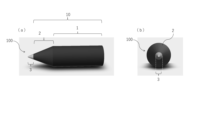
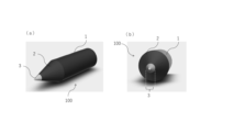
本実施形態のヘッドピンについて、図面を用いて説明する。図1は、本実施形態のヘッドピンの側面図と正面図である。図2は、本実施形態のヘッドピンの斜視図である。 The head pin of this embodiment will be described with reference to the drawings. FIG. 1 is a side view and a front view of the head pin of this embodiment. FIG. 2 is a perspective view of the head pin of this embodiment.
図1及び図2に示すように、ヘッドピン100は、体部10(軸部1とテーパー部2)と先端部3とを備える。先端部3は、体部10の先端に固定される。
As shown in FIGS. 1 and 2, the
図3は、体部10の強化繊維(1mmの炭素繊維)と樹脂(ビニルエステル)の組成比率(重量%)を変化させた場合の圧縮強度と内部空洞の有無の実験結果を示す表である。体部10は、主に強化繊維及び樹脂により組成されることから、低アーチファクトを実現することは可能であるが、適切な圧縮強度が必要である。
FIG. 3 is a table showing experimental results of compressive strength and the presence or absence of internal cavities when the composition ratio (% by weight) of the reinforcing fiber (1 mm carbon fiber) and resin (vinyl ester) of the
実験結果から、強化繊維の組成比率が増加すると圧縮強度が増加することが分かった。これにより、圧縮強度は強化繊維の組成比率に依存することが分かった。また、図4(a)に示すように、樹脂の組成比率が増加すると内部空洞が発生することが分かった。これにより、内部空洞は樹脂の組成比率に依存することが分かった。実際、図4(b)に示すように、樹脂のみで形成されたヘッドピンに内部空洞が発生していることを確認した。 From the experimental results, it was found that the compressive strength increased as the composition ratio of reinforcing fibers increased. As a result, it was found that the compressive strength depends on the composition ratio of the reinforcing fibers. Moreover, as shown in FIG. 4(a), it was found that internal cavities were generated as the composition ratio of the resin increased. From this, it was found that the internal cavity depends on the composition ratio of the resin. Actually, as shown in FIG. 4(b), it was confirmed that an internal cavity was generated in the head pin formed only of resin.
実験番号1,2では、それぞれ2700N、3000N以上の十分な圧縮強度があるが、樹脂の組成比率が高いことに起因して内部空洞が発生するため、ヘッドピンとしての性能を保証できない。つまり、内部空洞の位置や形状によっては、ヘッドピンとしての圧縮強度を得られない危険性がある。したがって、実験結果から、樹脂の組成比率が70重量%以下であることが適切である。 Experiment Nos. 1 and 2 have sufficient compressive strengths of 2700 N and 3000 N or more, respectively, but internal cavities occur due to the high composition ratio of the resin, so performance as a head pin cannot be guaranteed. In other words, depending on the position and shape of the internal cavity, there is a risk that the head pin will not have sufficient compressive strength. Therefore, according to experimental results, it is appropriate that the composition ratio of the resin is 70% by weight or less.
実験番号3,4では、それぞれ2700N、3000N以上の十分な圧縮強度があり、内部空洞も発生しないため、ヘッドピンとしての圧縮強度を得るためには、体部10は、30重量%以上の強化繊維(第1の強化繊維)の組成比率が必要である。 Experiment Nos. 3 and 4 had sufficient compressive strengths of 2700 N and 3000 N or more, respectively, and no internal cavities were generated. A composition ratio of (first reinforcing fibers) is required.
一方、強化繊維(第1の強化繊維)の組成比率を30重量%以上とし、樹脂の組成比率を70重量%以下とすると、体部10の内部空洞を防止しつつ圧縮強度を増加することができるが、樹脂の組成比率が30重量%未満となったとき、体部10を射出成型する際に、粘性が不十分となり射出成型がうまくできなかった。
On the other hand, when the composition ratio of the reinforcing fibers (first reinforcing fibers) is 30% by weight or more and the composition ratio of the resin is 70% by weight or less, it is possible to increase the compressive strength while preventing internal cavities in the
したがって、体部10の十分な圧縮強度を得ることができ、且つ射出成型に適した体部10の組成比率は、第1の強化繊維を30重量%乃至70重量%とし、樹脂を30重量%乃至70重量%とすることである。強化繊維は樹脂より高価であるため、より廉価でディスポーザビリティに優れたヘッドピンを提供するために、好ましくは、体部10の組成比率は、第1の強化繊維を30重量%乃至50重量%とし、樹脂を50重量%乃至70重量%とすることである。
Therefore, the composition ratio of the
このように、体部10は、30重量%乃至70重量%の第1の強化繊維と30重量%乃至70重量%の第1の樹脂を含む第1の強化プラスチックを有する。第1の強化プラスチックは、炭素繊維強化プラスチックが好ましいが、ガラス繊維強化プラスチック、カーボン繊維強化プラスチック、ボロン繊維強化プラスチック、アラミド繊維強化プラスチック、ケプラ繊維強化プラスチック、ダイニーマ繊維強化プラスチック、及びザイロン繊維強化プラスチックの少なくとも1つであっても、体部10の十分な圧縮強度を得られる。また、内部空洞及び射出成型時の粘性は樹脂の組成比率に依存するため、これらの強化繊維であっても、体部10の組成比率は炭素繊維と同様である。なお、一般的に、組成物である強化繊維の長さが長いほど強度が増加する。図3の実験では、1mmの炭素繊維を用いたが、0.5mm乃至5mmの炭素繊維を用いても十分な強度を得られることが分かっている。
Thus,
先端部3は、動物の頭部と接触可能であり、当該頭部を確実に固定するヘッドピンを提供するために、好ましくは、動物の頭部に突刺可能である。先端部3には特に力がかかるため、体部10の圧縮強度より高い圧縮強度が要求される。この場合、体部10の圧縮強度より高い圧縮強度は、先端部3の素材、形状、及びサイズの少なくとも1つに依存する。
The
また、先端部3によるアーチファクトも、先端部3の素材、形状、及びサイズの少なくとも1つに依存する。例えば、先端部3の素材が強化繊維である場合は、形状及びサイズにかかわらず、低アーチファクトを実現することができる。先端部3の素材が金属である場合は、アーチファクトを発生させやすいが、適切な形状及びサイズを選択することで、低アーチファクトを実現することができる。
Artifacts due to the
まず、先端部3の素材は、金属、セラミックス、サーメット、及び第2の強化プラスチックの少なくとも1つを含む素材である。
First, the material of the
頭部を確実に固定するためには、先端部3の素材は、金属、セラミックス、及びサーメットの少なくとも1つが好ましい。また、アーチファクトを低減するためには、先端部3の素材は、強化プラスチックが好ましい。
In order to securely fix the head, the material of the
次に、先端部3の形状及びサイズは、略錐体、略錐台、及び略回転体の少なくとも1つの形状を含む形状であり、アーチファクトを低減するために、当該形状の底面の長さの最大値が1.5mm乃至3mmであるサイズであることが好ましい。
Next, the shape and size of the
なお、先端部3のサイズは、アーチファクトを発生させやすい金属を基準に設定しており、それ以外の素材では、アーチファクトはより低減される。
Note that the size of the
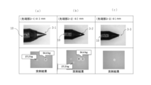
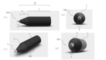
図5は、先端部の形状及びサイズの例を示す図である。素材は金属(チタン)である。図5では、先端部3-1,3-2,3-3は、略錐体(略回転体)30-1,30-2,30-3を含み、略錐体(略回転体)30-1,30-2,30-3の底面の長さがそれぞれ1mm、2mm、及び3mmである。 FIG. 5 is a diagram showing an example of the shape and size of the tip. The material is metal (titanium). In FIG. 5, the distal end portions 3-1, 3-2, 3-3 include substantially conical bodies (substantially rotating bodies) 30-1, 30-2, 30-3, and substantially conical bodies (substantially rotating bodies) 30 The bottom lengths of -1, 30-2, and 30-3 are 1 mm, 2 mm, and 3 mm, respectively.
また、先端部3-1,3-2,3-3は、体部10側に延伸する突起部31-1,31-2,31-3を含み、突起部31-1,31-2,31-3は、体部10に埋没することにより、先端部30-1,30-2,30-3を体部10に固定可能とする。
Further, the distal end portions 3-1, 3-2, 3-3 include protrusions 31-1, 31-2, 31-3 extending toward the
図5の突起部31-1,31-2,31-3は円柱形状であるが、体部10に固定する固定強度を高めるため、突起部31は、テーパー形状、ネジ形状、フランジ形状、及び矢じり形状の少なくとも1つを含んでもよい。体部10に固定する固定強度をより高めるため、好ましくは、突起部31はフランジ形状である。また、突起部31を体部10から着脱可能にして、より廉価でディスポーザビリティに優れたヘッドピンを提供するために、好ましくは、突起部31はネジ形状である。この場合、体部10の埋没孔(図示せず)は、ネジ形状の突起部31と螺合する形状を有する。
The projections 31-1, 31-2, and 31-3 in FIG. 5 are cylindrical, but in order to increase the fixing strength to be fixed to the
図6は、図5の先端部30-1,30-2,30-3(チタン製)をそれぞれ備えるヘッドピンを模擬骨に突刺した実験結果を示す図である。先端部30-1,30-2,30-3のそれぞれの突起部(図示せず)は、体部10側に延伸して、体部10に埋没している。図6では、ヘッドピンに27.2kg(60ポンド)と54.4kg(120ポンド)の力を加えて、先端部3を模擬骨に突刺した結果を示している。
FIG. 6 is a diagram showing the results of an experiment in which head pins each having tips 30-1, 30-2, and 30-3 (made of titanium) shown in FIG. 5 were pierced into simulated bones. Projections (not shown) of the distal ends 30-1, 30-2, and 30-3 extend toward the
図6(a)は、先端部30-1を備えるヘッドピンを模擬骨に突刺した実験結果を示す図である。両方の加重において、先端部30-1は模擬骨に突刺し、十分な圧縮強度と固定強度を示した。 FIG. 6(a) is a diagram showing the results of an experiment in which a head pin having a tip portion 30-1 was pierced into a simulated bone. At both loadings, the tip 30-1 penetrated the simulated bone and exhibited sufficient compressive strength and fixation strength.
図6(b)は、先端部30-2を備えるヘッドピンを模擬骨に突刺した実験結果を示す図である。両方の加重において、先端部30-2は模擬骨に突刺し、十分な圧縮強度と固定強度を示した。 FIG. 6(b) is a diagram showing the results of an experiment in which a head pin having a tip portion 30-2 was pierced into a simulated bone. At both loadings, tip 30-2 penetrated the simulated bone and exhibited sufficient compressive and anchoring strength.
図6(c)は、先端部30-3を備えるヘッドピンを模擬骨に突刺した実験結果を示す図である。27.2kg(60ポンド)の加重に到達する前に、先端部30-2の先端が曲がり、十分な圧縮強度と固定強度を示すことができなかった。 FIG. 6(c) is a diagram showing the results of an experiment in which a head pin having a tip portion 30-3 was pierced into a simulated bone. Before reaching a load of 27.2 kg (60 pounds), the tip of tip 30-2 bent and failed to exhibit sufficient compressive and anchoring strength.
なお、図6には示さないが、先端部3が略錐体(略回転体)を含み、当該略錐体(略回転体)の底面の長さが1.5mmである先端部3について、同様の実験を行った結果、両方の加重において、先端部30-2は模擬骨に突刺し、十分な圧縮強度と固定強度を示した。
Although not shown in FIG. 6, the
したがって、実験結果から、先端部3の十分な圧縮強度と固定強度を得るためには、当該略錐体(略回転体)の底面の長さが1.5mm以上であることが適切である。
Therefore, according to experimental results, in order to obtain sufficient compressive strength and fixing strength of the
次に、先端部3に含まれる略錐体(略回転体)の底面の長さが1mm、1.5mm、2mm、及び3mmであるヘッドピンによるアーチファクトの評価実験の結果を示す。 Next, the results of an artifact evaluation experiment using head pins whose base lengths are 1 mm, 1.5 mm, 2 mm, and 3 mm will be shown.
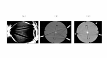
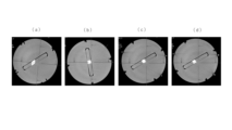
図7は、従来のヘッドピンのアーチファクトを示す図である。図8は、本実施形態のヘッドピンのアーチファクトを示す図である。動物の頭部を模したファントムにそれぞれのヘッドピンを3カ所で固定して、CT画像(コーンビームCT画像)を撮像した。 FIG. 7 is a diagram showing artifacts of a conventional head pin. FIG. 8 is a diagram showing artifacts of the headpin of this embodiment. A CT image (cone-beam CT image) was taken by fixing each head pin to a phantom imitating an animal's head at three points.
図7(a)は、ステンレスのヘッドピンのアーチファクトを示す図である。図7(b)は、サファイアのヘッドピンのアーチファクトを示す図である。図7(c)は、先端部にステンレスのキャップを装着したヘッドピンのアーチファクトを示す図である。 FIG. 7(a) is a diagram showing an artifact of a stainless steel head pin. FIG. 7(b) shows a sapphire headpin artifact. FIG. 7(c) is a diagram showing an artifact of a head pin with a stainless steel cap attached to the tip.
図8(a)は、先端部3に含まれる略錐体(略回転体)の底面の長さが1mmのヘッドピンによるアーチファクトを示す図である。図8(b)は、先端部3に含まれる略錐体(略回転体)の底面の長さが1.5mmのヘッドピンによるアーチファクトを示す図である。図8(c)は、先端部3に含まれる略錐体(略回転体)の底面の長さが2mmのヘッドピンによるアーチファクトを示す図である。図8(d)は、先端部3に含まれる略錐体(略回転体)の底面の長さが3mmのヘッドピンによるアーチファクトを示す図である。
FIG. 8(a) is a diagram showing an artifact caused by a head pin having a bottom surface length of 1 mm of a substantially conical body (substantially rotating body) included in the
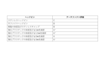
図9は、それぞれのヘッドピンのアーチファクトを評価した表を示す。図7のCT画像では、ヘッドピンの先端部から放射線状にアーチファクトが発生し、評価はC,Bと低かった。図8のCT画像では、先端部3に含まれる略錐体(略回転体)の底面の長さが長くなるほどヘッドピンの先端部から放射線状にアーチファクトが発生するが、評価はA+,A,A-と高かった。評価はA-まで許容される。
FIG. 9 shows a table evaluating the artifacts of each headpin. In the CT image of FIG. 7, artifacts were generated radially from the tip of the head pin, and the evaluation was as low as C and B. In the CT image of FIG. 8, the longer the length of the bottom surface of the substantially cone (substantially rotating body) included in the
したがって、先端部3の十分な圧縮強度と固定強度を考慮すると、先端部3に含まれる略錐体(略回転体)の底面の長さは1.5mm以上であり、低アーチファクトを考慮すると、先端部3に含まれる略錐体(略回転体)の底面の長さは3mm以下であることが適切である。先端部3の十分な圧縮強度と固定強度及び低アーチファクトの両立を考慮すると、先端部3に含まれる略錐体(略回転体)の底面の長さは1.5mm以上2.5mm以下であることが好ましい。さらには、先端部3に含まれる略錐体(略回転体)の底面の長さは1.5mm以上2mm以下であることが好ましい。
Therefore, considering the sufficient compressive strength and fixing strength of the
チタンの他、先端部3は、ステンレス、鉄、ニッケル、コバルト、及び超硬合金の少なくとも1つを金属として含んでもよい。
Besides titanium, the
以上、本発明にかかる実施形態について説明したが、本発明はこれらに限定されるものではなく、請求項に記載された範囲内において変更・変形することが可能である。 Although the embodiments according to the present invention have been described above, the present invention is not limited to these, and can be changed and modified within the scope described in the claims.
第1の強化プラスチックと同様の理由で、第2の強化プラスチックは、30重量%乃至70重量%の第2の強化繊維と30重量%乃至70重量%の第2の樹脂を含む強化プラスチックであればよい。第2の強化プラスチックは、第1の強化繊維より高圧縮強度の強化プラスチックであることが好ましい。したがって、第2の強化プラスチックは、50重量%乃至70重量%の第2の強化繊維と30重量%乃至50重量%の第2の樹脂を含む強化プラスチックであることが好ましい。また、第1の強化プラスチックと同様、第2の強化プラスチックは、炭素繊維強化プラスチックであることが好ましいが、その他の強化プラスチックであってもよい。 For the same reason as the first reinforced plastic, the second reinforced plastic is a reinforced plastic containing 30% to 70% by weight of the second reinforcing fiber and 30% to 70% by weight of the second resin. Just do it. The second reinforced plastic is preferably a reinforced plastic having a compression strength higher than that of the first reinforced fiber. Therefore, the second reinforced plastic is preferably a reinforced plastic containing 50% to 70% by weight of the second reinforcing fiber and 30% to 50% by weight of the second resin. Also, like the first reinforced plastic, the second reinforced plastic is preferably carbon fiber reinforced plastic, but may be another reinforced plastic.
また、樹脂は、熱硬化性樹脂及び熱可塑性樹脂の少なくとも1つを含む。例えば、樹脂は、エポキシ系、フェノール系、及び不飽和ポリエステル系等の樹脂から選択されればよい。 Also, the resin includes at least one of a thermosetting resin and a thermoplastic resin. For example, the resin may be selected from epoxy-based, phenolic-based, and unsaturated polyester-based resins.
また、先端部3は、図10に示すような形状であってもよい。この形状も、略錐体に含まれる。
Moreover, the
本発明は、ディスポーザビリティに優れ、アーチファクトを軽減できるヘッドピンとして有用である。 INDUSTRIAL APPLICABILITY The present invention is useful as a head pin that has excellent disposability and can reduce artifacts.
1…軸部
2…テーパー部
3,30…先端部
10…体部
31…突起部
100…ヘッドピン
DESCRIPTION OF
Claims (10)
30重量%乃至70重量%の第1の強化繊維と30重量%乃至70重量%の第1の樹脂を含む第1の強化プラスチックを有する前記ヘッドピンの体部と、
前記体部の先端に固定され、前記頭部と接触可能であり、金属、セラミックス、サーメット、及び第2の強化プラスチックの少なくとも1つを含む前記ヘッドピンの先端部と、
を備えることを特徴とするヘッドピン。 A head pin capable of fixing the head of an animal,
a body portion of the head pin having a first reinforced plastic containing 30% to 70% by weight of the first reinforcing fiber and 30% to 70% by weight of the first resin;
a tip of the head pin fixed to the tip of the body, contactable with the head, and comprising at least one of metal, ceramics, cermet, and a second reinforced plastic;
A headpin comprising:
前記突起部は、前記体部に埋没することにより、前記先端部を前記体部に固定可能とすることを特徴とする請求項1乃至請求項8の何れか1項に記載のヘッドピン。 The tip includes a protrusion extending toward the body,
9. The head pin according to any one of claims 1 to 8, wherein the protrusion is embedded in the body so that the tip can be fixed to the body.
Priority Applications (6)
| Application Number | Priority Date | Filing Date | Title |
|---|---|---|---|
| JP2021206525A JP2023091663A (en) | 2021-12-20 | 2021-12-20 | head pin |
| EP22911245.3A EP4454596A4 (en) | 2021-12-20 | 2022-12-20 | HEADPEN |
| KR1020247020661A KR20240115852A (en) | 2021-12-20 | 2022-12-20 | head pin |
| CN202280083402.5A CN118434382A (en) | 2021-12-20 | 2022-12-20 | Head Pin |
| PCT/JP2022/046974 WO2023120543A1 (en) | 2021-12-20 | 2022-12-20 | Head pin |
| US18/748,374 US20240341811A1 (en) | 2021-12-20 | 2024-06-20 | Skull pin |
Applications Claiming Priority (1)
| Application Number | Priority Date | Filing Date | Title |
|---|---|---|---|
| JP2021206525A JP2023091663A (en) | 2021-12-20 | 2021-12-20 | head pin |
Publications (1)
| Publication Number | Publication Date |
|---|---|
| JP2023091663A true JP2023091663A (en) | 2023-06-30 |
Family
ID=86902551
Family Applications (1)
| Application Number | Title | Priority Date | Filing Date |
|---|---|---|---|
| JP2021206525A Pending JP2023091663A (en) | 2021-12-20 | 2021-12-20 | head pin |
Country Status (6)
| Country | Link |
|---|---|
| US (1) | US20240341811A1 (en) |
| EP (1) | EP4454596A4 (en) |
| JP (1) | JP2023091663A (en) |
| KR (1) | KR20240115852A (en) |
| CN (1) | CN118434382A (en) |
| WO (1) | WO2023120543A1 (en) |
Citations (3)
| Publication number | Priority date | Publication date | Assignee | Title |
|---|---|---|---|---|
| JP2007268262A (en) * | 2006-03-31 | 2007-10-18 | Stryker Trauma Sa | External fixing implement element |
| US20080251086A1 (en) * | 2007-04-13 | 2008-10-16 | Dinkler Charles E | Limited artifact skull pin |
| US20150202012A1 (en) * | 2009-02-26 | 2015-07-23 | Pro Med Instruments Gmbh | Method and Apparatus for a Radiolucent and MRI Compatible Cranial Stabilization Pin |
Family Cites Families (11)
| Publication number | Priority date | Publication date | Assignee | Title |
|---|---|---|---|---|
| US5122132A (en) * | 1991-08-01 | 1992-06-16 | Bremer Medical, Inc. | Skull pin with enhanced shear resistance |
| JP2716047B2 (en) * | 1991-10-18 | 1998-02-18 | 株式会社東海理化電機製作所 | Medical skull fixation frame |
| DE4434519A1 (en) * | 1994-09-27 | 1996-03-28 | Brainlab Med Computersyst Gmbh | Fixing pin for fixing reference system in bone structure, esp. for head ring for neurosurgery |
| JP2004089456A (en) * | 2002-08-30 | 2004-03-25 | Mizuho Co Ltd | Headpin and apparatus for fixing head by using the same |
| JP2005342335A (en) | 2004-06-04 | 2005-12-15 | Mizuho Co Ltd | Head fixing device |
| EP2014251B1 (en) * | 2007-07-10 | 2012-05-30 | BrainLAB AG | Attachment device for securing a body made of polyphenyls in position for medical purposes and attachment device for securing a silicon nitride ceramic body in position for medical purposes |
| US8623029B2 (en) * | 2008-03-12 | 2014-01-07 | Neurologica Corp. | Composite skull pins with reduced X-ray signature |
| US9078679B2 (en) * | 2009-02-26 | 2015-07-14 | Pro Med Instruments Gmbh | Method and apparatus for a radiolucent and MRI compatible cranial stabilization pin |
| US8915914B2 (en) * | 2012-07-25 | 2014-12-23 | Orthofix S.R.L. | Method for treating a fracture of a bone having a medullary canal |
| KR20180078188A (en) * | 2018-05-17 | 2018-07-09 | 주식회사 카본티씨지 | Carbon composite skull pin |
| BR112021018063A2 (en) * | 2019-03-11 | 2021-11-23 | Nicoventures Trading Ltd | Aerosol delivery device and aerosol delivery system |
-
2021
- 2021-12-20 JP JP2021206525A patent/JP2023091663A/en active Pending
-
2022
- 2022-12-20 EP EP22911245.3A patent/EP4454596A4/en active Pending
- 2022-12-20 CN CN202280083402.5A patent/CN118434382A/en active Pending
- 2022-12-20 KR KR1020247020661A patent/KR20240115852A/en active Pending
- 2022-12-20 WO PCT/JP2022/046974 patent/WO2023120543A1/en not_active Ceased
-
2024
- 2024-06-20 US US18/748,374 patent/US20240341811A1/en active Pending
Patent Citations (3)
| Publication number | Priority date | Publication date | Assignee | Title |
|---|---|---|---|---|
| JP2007268262A (en) * | 2006-03-31 | 2007-10-18 | Stryker Trauma Sa | External fixing implement element |
| US20080251086A1 (en) * | 2007-04-13 | 2008-10-16 | Dinkler Charles E | Limited artifact skull pin |
| US20150202012A1 (en) * | 2009-02-26 | 2015-07-23 | Pro Med Instruments Gmbh | Method and Apparatus for a Radiolucent and MRI Compatible Cranial Stabilization Pin |
Also Published As
| Publication number | Publication date |
|---|---|
| WO2023120543A1 (en) | 2023-06-29 |
| CN118434382A (en) | 2024-08-02 |
| KR20240115852A (en) | 2024-07-26 |
| EP4454596A1 (en) | 2024-10-30 |
| US20240341811A1 (en) | 2024-10-17 |
| EP4454596A4 (en) | 2025-12-31 |
Similar Documents
| Publication | Publication Date | Title |
|---|---|---|
| JP5696053B2 (en) | Implant system for stabilizing bone | |
| EP0913131A3 (en) | Intra-articular tendon sling fixation screw | |
| CA2004569C (en) | Implantable fixing means for extraoral applications | |
| EP3597119A3 (en) | Permanent attachment means for curved tip of component of surgical stapling instrument | |
| US9078679B2 (en) | Method and apparatus for a radiolucent and MRI compatible cranial stabilization pin | |
| EP2522283A3 (en) | Clip and clipping instrument for biological tissues | |
| WO2003103733A8 (en) | SURGICAL THREAD </ = APTOS> / = FOR AESTHETIC SURGERY OPERATIONS | |
| CA2467180A1 (en) | Suture anchor with improved drive head | |
| US8623029B2 (en) | Composite skull pins with reduced X-ray signature | |
| EP1304080A3 (en) | Surgical ribbon file | |
| ATE379996T1 (en) | IMPLANT | |
| US20040162614A1 (en) | Flexible auditory ossicles prosthesis | |
| JP2023091663A (en) | head pin | |
| FI59919C (en) | KROEKT BENSPIK | |
| CN109171921B (en) | Novel design and manufacture of bone nail easy to screw in | |
| US9833289B2 (en) | Method and apparatus for a radiolucent and MRI compatible cranial stabilization pin | |
| US20220000528A1 (en) | Modular Head Compression Screw System and Device | |
| TWI308500B (en) | ||
| CN208942347U (en) | A kind of orthopaedics novel hollow screw | |
| US9167362B2 (en) | Implantable receptacle for a hearing aid component | |
| KR101583528B1 (en) | Stacking type prostheses for bone fracture healing | |
| CN2358847Y (en) | Bone screw | |
| CN202982200U (en) | Multiaxial universal nail | |
| CN119584929A (en) | Bone screws | |
| EP4523662A3 (en) | Rearfoot realignment and stabilization plate |
Legal Events
| Date | Code | Title | Description |
|---|---|---|---|
| A711 | Notification of change in applicant |
Free format text: JAPANESE INTERMEDIATE CODE: A711 Effective date: 20221214 |
|
| A521 | Request for written amendment filed |
Free format text: JAPANESE INTERMEDIATE CODE: A821 Effective date: 20221215 |
|
| RD02 | Notification of acceptance of power of attorney |
Free format text: JAPANESE INTERMEDIATE CODE: A7422 Effective date: 20231002 |
|
| A521 | Request for written amendment filed |
Free format text: JAPANESE INTERMEDIATE CODE: A821 Effective date: 20231002 |
|
| RD04 | Notification of resignation of power of attorney |
Free format text: JAPANESE INTERMEDIATE CODE: A7424 Effective date: 20231027 |
|
| A621 | Written request for application examination |
Free format text: JAPANESE INTERMEDIATE CODE: A621 Effective date: 20241031 |
|
| A131 | Notification of reasons for refusal |
Free format text: JAPANESE INTERMEDIATE CODE: A131 Effective date: 20251007 |
|
| A521 | Request for written amendment filed |
Free format text: JAPANESE INTERMEDIATE CODE: A523 Effective date: 20251127 |
|
| RD07 | Notification of extinguishment of power of attorney |
Free format text: JAPANESE INTERMEDIATE CODE: A7427 Effective date: 20251212 |
|
| A521 | Request for written amendment filed |
Free format text: JAPANESE INTERMEDIATE CODE: A821 Effective date: 20251212 |
|
| A131 | Notification of reasons for refusal |
Free format text: JAPANESE INTERMEDIATE CODE: A131 Effective date: 20260303 |
|
| A521 | Request for written amendment filed |
Free format text: JAPANESE INTERMEDIATE CODE: A523 Effective date: 20260305 |