JP2023077458A - BATTERY STORAGE DEVICE, METHOD OF MANUFACTURING BATTERY STORAGE DEVICE, AND ELECTRIC MOVING BODY INCLUDING THIS BATTERY STORAGE DEVICE - Google Patents

BATTERY STORAGE DEVICE, METHOD OF MANUFACTURING BATTERY STORAGE DEVICE, AND ELECTRIC MOVING BODY INCLUDING THIS BATTERY STORAGE DEVICE Download PDF

Info

Publication number
JP2023077458A
JP2023077458A JP2021190710A JP2021190710A JP2023077458A JP 2023077458 A JP2023077458 A JP 2023077458A JP 2021190710 A JP2021190710 A JP 2021190710A JP 2021190710 A JP2021190710 A JP 2021190710A JP 2023077458 A JP2023077458 A JP 2023077458A
Authority
JP
Japan
Prior art keywords
storage device
battery storage
module case
battery
case
Prior art date
Legal status (The legal status is an assumption and is not a legal conclusion. Google has not performed a legal analysis and makes no representation as to the accuracy of the status listed.)
Granted
Application number
JP2021190710A
Other languages
Japanese (ja)
Other versions
JP7766477B2 (en
Inventor
昌浩 石川
Masahiro Ishikawa
晋 甲野
Shin Kono
達也 杉森
Tatsuya Sugimori
英聰 薮
Hidetoshi Yabu
惇史 古瀬
Atsushi Furuse
直哉 松本
Naoya Matsumoto
雅憲 沖津
Masanori Okitsu
寛 横内
Hiroshi Yokouchi
Current Assignee (The listed assignees may be inaccurate. Google has not performed a legal analysis and makes no representation or warranty as to the accuracy of the list.)
Sanko Gosei Ltd
Original Assignee
Sanko Gosei Ltd
Priority date (The priority date is an assumption and is not a legal conclusion. Google has not performed a legal analysis and makes no representation as to the accuracy of the date listed.)
Filing date
Publication date
Application filed by Sanko Gosei Ltd filed Critical Sanko Gosei Ltd
Priority to JP2021190710A priority Critical patent/JP7766477B2/en
Publication of JP2023077458A publication Critical patent/JP2023077458A/en
Priority to JP2025181797A priority patent/JP2026016620A/en
Application granted granted Critical
Publication of JP7766477B2 publication Critical patent/JP7766477B2/en
Active legal-status Critical Current
Anticipated expiration legal-status Critical

Links

Images

Classifications

    • YGENERAL TAGGING OF NEW TECHNOLOGICAL DEVELOPMENTS; GENERAL TAGGING OF CROSS-SECTIONAL TECHNOLOGIES SPANNING OVER SEVERAL SECTIONS OF THE IPC; TECHNICAL SUBJECTS COVERED BY FORMER USPC CROSS-REFERENCE ART COLLECTIONS [XRACs] AND DIGESTS
    • Y02TECHNOLOGIES OR APPLICATIONS FOR MITIGATION OR ADAPTATION AGAINST CLIMATE CHANGE
    • Y02EREDUCTION OF GREENHOUSE GAS [GHG] EMISSIONS, RELATED TO ENERGY GENERATION, TRANSMISSION OR DISTRIBUTION
    • Y02E60/00Enabling technologies; Technologies with a potential or indirect contribution to GHG emissions mitigation
    • Y02E60/10Energy storage using batteries

Landscapes

  • Secondary Cells (AREA)
  • Battery Mounting, Suspending (AREA)

Abstract

To provide a battery storage device which improves storage space efficiency and cooling efficiency and is also advantageous in terms of cost, a manufacturing method of the battery storage device and an electrically-driven mobile with the battery storage device.SOLUTION: A battery storage device 1 comprises an aluminum battery case 2 and a resin module case 4 which is stored in the battery case 2 and in which a lithium ion battery 3 can be stored. The resin module case 4 is stored inside of the battery case 2 in a mode that an outer side face of the resin module case 4 is fitted to an inner side face of the battery case 2, a cooling water path 5 is formed in the resin module case 4 per se, and a height of the battery storage device 1 can be reduced. Namely, improvement of space efficiency can be attained. Further, the cooling water path 5 is formed in the resin module case 4 per se and the resin module case 4 includes the integrated cooling water path 5, such that cooking efficiency is also improved as a result.SELECTED DRAWING: Figure 1

Description

本発明は電動移動体に使用されるバッテリー収納装置及びバッテリー収納装置の製造方法とこのバッテリー収納装置を備える電動移動体に関し、とくに、全体の高さを低くして、狭いスペースに収納可能なバッテリー収納装置及びバッテリー収納装置の製造方法とこのバッテリー収納装置を備える電動移動体に関する。 TECHNICAL FIELD The present invention relates to a battery storage device used in an electric vehicle, a method for manufacturing the battery storage device, and an electric vehicle equipped with the battery storage device. The present invention relates to a storage device, a method for manufacturing a battery storage device, and an electric vehicle equipped with this battery storage device.

一般に冷却方式は空冷又は水冷又は冷媒による冷却方式に分類される。このうち自然空冷は構造簡単であるもののバッテリ性能に限界があり、またバッテリの寿命が比較的短期であるという欠点がある。また開放型強制空冷は構造簡単であるものの温度制御できないという問題がある。さらに密閉型強制空冷では水冷の場合のような水漏れの問題がない反面、水冷よりも冷却が困難でありまたファン/ダクトスペースが必要となるという問題がある。 Cooling systems are generally classified as air cooling, water cooling, or refrigerant cooling. Of these, natural air cooling has a simple structure, but has the drawback that the battery performance is limited and the life of the battery is relatively short. In addition, although the open type forced air cooling has a simple structure, there is a problem that the temperature cannot be controlled. Furthermore, although closed forced air cooling does not have the problem of water leakage as in the case of water cooling, it is more difficult to cool than water cooling and requires fan/duct space.

また水以外の液体を冷媒として用いる冷媒直冷は、冷却効果が高く冷却制御容易であるという利点があるものの冷媒漏れ防止対策が必要となる。 Direct cooling using a liquid other than water as a refrigerant has the advantages of high cooling effect and easy cooling control, but requires countermeasures to prevent leakage of the refrigerant.

さらに水を用いる冷却方式、すなわち水冷方式であるラジエター方式は構造が簡単であるものの外気温以下に冷却できないという問題がある。またこれも水冷方式であるチラー方式は構造簡単で確実に冷却できるという利点がある反面、バッテリーを温めることができという問題もある。
ラジエターとチラーのハイブリット方式は冷却制御が容易であるものの構造複雑になり、また水漏れの問題の可能性が指摘されている。
Furthermore, the cooling system using water, that is, the radiator system, which is a water-cooling system, has a simple structure, but has the problem that it cannot cool below the outside air temperature. The chiller system, which is also a water-cooling system, has the advantage of being simple in structure and capable of cooling reliably, but has the problem of being unable to heat the battery.
The radiator/chiller hybrid system makes it easy to control cooling, but the structure is complicated, and the possibility of water leakage has been pointed out.

以上の各種冷却方式の中で水冷方式によるバッテリー用冷却装置では、バッテリーケースと、そのバッテリーケースに収納するモジュールケースと、そのモジュールケース内に複数のバッテリーを収納する方式が従来から採用されている。
係るバッテリーモジュール方式を採用することによってバッテリー組付け工程のシンプル化を行うことが可能となる。具体的にはバッテリーを1つ1つバッテリーケースに入れてその各バッテリーの固定と配線接続を行う作業を行う場合にバッテリー組付け工程工数が膨大となる問題を解消し、生産性を飛躍的に向上することができる。またそのようにバッテリーモジュールを採用することによってバッテリー組付け工程のサブライン化や別の場所での作業にすることができ、工程設計の自由度が上がる。
Among the various cooling methods described above, water-cooled battery cooling devices have conventionally adopted a method in which a battery case, a module case that is housed in the battery case, and a plurality of batteries are housed in the module case. .
By adopting such a battery module system, it becomes possible to simplify the battery assembly process. Specifically, it solves the problem that the number of man-hours required for the battery assembly process is enormous when each battery is placed in a battery case and the work of fixing and wiring each battery is performed, and productivity is dramatically improved. can be improved. In addition, by adopting the battery module in this way, the battery assembly process can be sub-lined or the work can be done at a different location, increasing the degree of freedom in process design.

係る従来方式に関し特許文献1に示すバッテリー用冷却装置にあってはバッテリーモジュール100は、図23に示すように、前後方向に積層した複数のバッテリーセル101と、複数のバッテリーセル101を収容するモジュールケース105とを備えている。 Regarding such a conventional method, in the battery cooling device disclosed in Patent Document 1, as shown in FIG. A case 105 is provided.

さらにバッテリーケース200は、図24に示すように、略水平な板状をなすロアケース201と、ロアケース201に対し上から覆うように組み付けられたカバー206とを備えている。 Further, as shown in FIG. 24, the battery case 200 includes a substantially horizontal plate-shaped lower case 201 and a cover 206 assembled to cover the lower case 201 from above.

図25に示すように複数のバッテリーモジュール100をロアケース201に固定した後、バッテリーモジュー ル100を上から覆い隠すようにカバー206を被せ、被せたカバー206をボルト等によってロアケース201に固定する。以上により、バッテリーケース200が構成されるとともに、バッテリーケース200内に複数のバッテリーモジュール100が固定された状態で収容される。 After fixing a plurality of battery modules 100 to the lower case 201 as shown in FIG. 25, a cover 206 is placed to cover the battery modules 100 from above, and the cover 206 is fixed to the lower case 201 with bolts or the like. As described above, the battery case 200 is configured, and the plurality of battery modules 100 are accommodated in the battery case 200 in a fixed state.

特開2018-163741号公報JP 2018-163741 A

特許文献1に開示されたバッテリー収納装置では図26に示すようにバッテリーモジュール100の下面とロアケース201の底板部202の上面との間に冷却器300が配置される。その結果ロアケース201の底板部202、バッテリーモジュール100、冷却器300それぞれの高さを加算した地上高を生じる収納スペースが必要となる。しかもバッテリーモジュール100、冷却器300が上下に隣接して配置されて単にバッテリーモジュール100が下面から冷却されるだけであり、その冷却効率には限界があった。またそのような部品構成であることから部品点数が多くなり、部品コストが嵩むという問題もあった。 In the battery storage device disclosed in Patent Document 1, a cooler 300 is arranged between the lower surface of the battery module 100 and the upper surface of the bottom plate portion 202 of the lower case 201 as shown in FIG. As a result, a storage space is required that provides a ground clearance obtained by adding the respective heights of the bottom plate portion 202 of the lower case 201, the battery module 100, and the cooler 300. FIG. Moreover, since the battery modules 100 and the coolers 300 are arranged vertically adjacent to each other, the battery modules 100 are simply cooled from the bottom surface, and the cooling efficiency is limited. In addition, there is also a problem that the number of parts is increased due to such a part configuration, and the part cost is increased.

本発明は以上の従来技術に関する問題に鑑み、収納スペース効率、冷却効率が良く、部品コストの点からも有利なバッテリー収納装置及びバッテリー収納装置の製造方法とこのバッテリー収納装置を備える電動移動体を提供することを目的とする。 In view of the problems related to the prior art, the present invention provides a battery storage device that has good storage space efficiency, cooling efficiency, and is advantageous in terms of parts cost, a method for manufacturing the battery storage device, and an electric vehicle equipped with this battery storage device. intended to provide

すなわち本発明のバッテリー収納装置は、バッテリーケースと、そのバッテリーケースに収納されてバッテリーを収納可能にされたモジュールケースとを備えるバッテリー収納装置において、前記モジュールケース自体が温度調整液体経路を有することを特徴とする。 That is, the battery storage device of the present invention is a battery storage device comprising a battery case and a module case that is housed in the battery case and is capable of housing a battery, wherein the module case itself has a temperature-adjusting liquid path. Characterized by

また本発明のバッテリー収納装置は、バッテリーケースと、そのバッテリーケースに収納されてバッテリーを収納可能にされたモジュールケースとを備えるバッテリー収納装置において、前記モジュールケースと一体な温度調整液体経路を有することを特徴とする。 Further, the battery storage device of the present invention is a battery storage device comprising a battery case and a module case that is housed in the battery case so that the battery can be stored therein, wherein the module case has a temperature control liquid path integral with the module case. characterized by

さらに本発明のバッテリー収納装置は、バッテリーケースと、そのバッテリーケースに収納されてバッテリーを収納可能にされたモジュールケースとを備えるバッテリー収納装置において、前記モジュールケースに温度調整液体経路が形成されてなることを特徴とする。 Further, the battery storage device of the present invention is a battery storage device comprising a battery case and a module case which is housed in the battery case and is capable of housing a battery, wherein the module case is formed with a temperature control liquid path. It is characterized by

また本発明のバッテリー収納装置の製造方法は、本発明のバッテリー収納装置の製造方法であって、樹脂射出成形によってモジュールケースの底部と側部とを一体に形成し、温度調整液体経路が形成された本体部を得る工程と、前記温度調整液体経路の開口部分にボトムパネルを溶着して前記モジュールケースを得る工程とよりなることを特徴とする。 A method for manufacturing a battery storage device according to the present invention is a method for manufacturing a battery storage device according to the present invention, in which the bottom and side portions of the module case are integrally formed by resin injection molding to form a temperature control liquid path. and a step of welding a bottom panel to the opening of the temperature-adjusting liquid path to obtain the module case.

さらに本発明のバッテリー収納装置の製造方法は、本発明のバッテリー収納装置の製造方法であって、予めモジュールケース本体部とモジュールケース配管カットモデルとを射出成型する工程と、前記モジュールケース配管カットモデルを前記モジュールケース本体部に振動溶着する工程とよりなることを特徴とする。
ことを特徴とする。
Further, a method of manufacturing a battery storage device according to the present invention is a method of manufacturing a battery storage device according to the present invention, comprising a step of injection-molding a module case main body and a module case piping cut model in advance, and is vibration-welded to the module case main body.
It is characterized by

加えて本発明の電動移動体は、本発明のバッテリー収納装置を備える電動移動体であって、バッテリー収納装置が移動体の駆動力を生じるモータに電力を供給するようにしてなることを特徴とする。 In addition, an electric vehicle of the present invention is an electric vehicle equipped with the battery storage device of the present invention, and is characterized in that the battery storage device supplies electric power to a motor that generates a driving force of the vehicle. do.

本発明のバッテリー収納装置及びバッテリー収納装置の製造方法とこのバッテリー収納装置を備える電動移動体によれば、収納スペース効率、冷却効率が良く、部品コストの点からも有利であるという優れた効果が奏される。 According to the battery storage device, the manufacturing method of the battery storage device, and the electric vehicle provided with the battery storage device of the present invention, the storage space efficiency, the cooling efficiency, and the parts cost can be reduced. played.

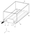
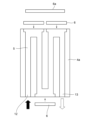
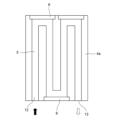
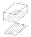
本発明の一実施の形態に係るバッテリー収納装置の模式断面図である。1 is a schematic cross-sectional view of a battery storage device according to an embodiment of the invention; FIG. 図1のバッテリー収納装置の分解斜視図である。FIG. 2 is an exploded perspective view of the battery storage device of FIG. 1; 本発明の他の実施の形態に係るバッテリー収納装置の模式断面図である。FIG. 4 is a schematic cross-sectional view of a battery storage device according to another embodiment of the invention; 本発明のバッテリー収納装置によるバッテリー収納状態の例を示す斜視図であり、(a)バッテリーの下面冷却時のバッテリー配列、(b)バッテリーの側面冷却時のバッテリー配列、である。FIG. 4 is a perspective view showing an example of a battery housing state in the battery housing apparatus of the present invention, (a) battery arrangement when cooling the lower surface of the battery, and (b) battery arrangement when cooling the side surface of the battery. 本発明の一実施の形態のバッテリー収納装置における温度調整液体経路の一パターンを示す模式図である。FIG. 4 is a schematic diagram showing one pattern of temperature-adjusting liquid paths in the battery storage device according to the embodiment of the present invention; 本発明の一実施の形態のバッテリー収納装置における温度調整液体経路の他のパターンを示す模式図である。FIG. 5 is a schematic diagram showing another pattern of the temperature-adjusting liquid path in the battery storage device according to the embodiment of the present invention; 本発明の一実施の形態のバッテリー収納装置における温度調整液体経路の別のパターンを示す模式図である。FIG. 4 is a schematic diagram showing another pattern of the temperature-adjusting liquid path in the battery storage device according to the embodiment of the present invention; 本発明の一実施の形態のバッテリー収納装置における温度調整液体経路のまた別のパターンを示す模式図である。FIG. 5 is a schematic diagram showing another pattern of the temperature-adjusting liquid path in the battery storage device according to the embodiment of the present invention; 本発明の他の実施の形態に係るバッテリー収納装置の部分斜視図である。FIG. 4 is a partial perspective view of a battery storage device according to another embodiment of the present invention; 本発明の他の実施の形態に係るバッテリー収納装置の部分模式図である。FIG. 5 is a partial schematic diagram of a battery storage device according to another embodiment of the present invention; 本発明のさらに他の実施の形態に係るバッテリー収納装置の部分模式図である。FIG. 5 is a partial schematic diagram of a battery storage device according to still another embodiment of the present invention; 本発明のさらに他の実施の形態に係るバッテリー収納装置の部分斜視図であり、(a)組付け工程を示す、(b)組付け後を示す。It is a partial perspective view of the battery storage device which concerns on further another embodiment of this invention, (a) shows an assembly process, (b) shows after assembly. 図12(b)の部分拡大斜視図である。FIG. 12B is a partially enlarged perspective view of FIG. 本発明のさらに他の実施の形態に係るバッテリー収納装置の組付け工程を示す部分分解斜視図である。FIG. 11 is a partially exploded perspective view showing a process of assembling a battery storage device according to still another embodiment of the present invention; 図14に示す実施の形態のバッテリー収納装置の組付け後を示す部分斜視図である。FIG. 15 is a partial perspective view showing the battery storage device of the embodiment shown in FIG. 14 after assembly; 図15に示す実施の形態のバッテリー収納装置の横断面図である。FIG. 16 is a cross-sectional view of the battery storage device of the embodiment shown in FIG. 15; 本発明のバッテリー収納装置の製造方法の一実施の形態の説明図である。FIG. 4 is an explanatory diagram of one embodiment of the method for manufacturing the battery storage device of the present invention; 本発明のバッテリー収納装置の製造方法の一実施の形態の他の説明図である。FIG. 10 is another explanatory view of one embodiment of the method for manufacturing the battery storage device of the present invention; 本発明のバッテリー収納装置の製造方法の一実施の形態のまた他の説明図である。FIG. 10 is yet another explanatory view of one embodiment of the method for manufacturing the battery storage device of the present invention; 本発明のバッテリー収納装置の製造方法の他の実施の形態の説明斜視図である。FIG. 8 is an explanatory perspective view of another embodiment of the method for manufacturing the battery storage device of the present invention; 図20に示す実施の形態の他の説明斜視図である。Figure 21 is another illustrative perspective view of the embodiment shown in Figure 20; 本発明の電動移動体の一実施の形態の側面透視模式図である。FIG. 1 is a schematic perspective side view of an embodiment of an electric vehicle of the present invention; 従来のバッテリー用冷却装置におけるバッテリーモジュールの分解斜視図である。1 is an exploded perspective view of a battery module in a conventional battery cooling device; FIG. 従来のバッテリー用冷却装置におけるバッテリーケースの斜視図である。FIG. 10 is a perspective view of a battery case in a conventional battery cooling device; 従来のバッテリー用冷却装置のバッテリーケースにおけるバッテリーモジュールの収納状態を示す部分斜視図である。FIG. 11 is a partial perspective view showing a state in which a battery module is accommodated in a battery case of a conventional battery cooling device; 従来のバッテリー用冷却装置におけるバッテリーケースの部分断面模式図である。FIG. 3 is a schematic partial cross-sectional view of a battery case in a conventional battery cooling device;

以下に、本発明の実施形態を図面に基づいて説明する。
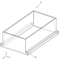
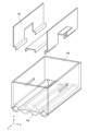
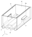
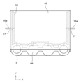
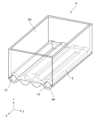
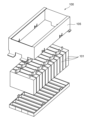
図1、図2に示す本発明の一実施の形態に係るバッテリー収納装置1は、アルミ製のバッテリーケース2と、そのバッテリーケース2に収納されてリチウムイオンバッテリー3を収納可能にされた樹脂製モジュールケース4とを備える。バッテリーケース2の内側面に樹脂製モジュールケース4の外側面が嵌合する態様で、バッテリーケース2の内側に樹脂製モジュールケース4が収納される。
この本発明の一実施の形態に係るバッテリー収納装置1にあっては樹脂製モジュールケース4自体が温度調整液体経路である冷却水経路5を有する。すなわち樹脂製モジュールケース4自体に冷却水経路5が形成されて、樹脂製モジュールケース4が一体な冷却水経路5を有する。温度調整液体経路の態様としては加温若しくは加熱水経路とすることもある。
An embodiment of the present invention will be described below with reference to the drawings.
A battery storage device 1 according to one embodiment of the present invention shown in FIGS. A module case 4 is provided. The resin module case 4 is accommodated inside the battery case 2 in such a manner that the outer surface of the resin module case 4 is fitted to the inner surface of the battery case 2 .
In the battery storage device 1 according to the embodiment of the present invention, the resin module case 4 itself has the cooling water path 5 which is the temperature adjusting liquid path. That is, the cooling water path 5 is formed in the resin module case 4 itself, and the resin module case 4 has the cooling water path 5 integrated therewith. The mode of the temperature-adjusting liquid path may be a heating or heating water path.

さらに詳細には樹脂製モジュールケース4の下面には凹所5aが形成され、その凹所5aの開口部分5bがボトムパネル6によって閉塞されて冷却水経路5が形成される。樹脂製モジュールケース4の下面とボトムパネル6上面との間にはOリング7が配置されて止水が図られ、その状態で樹脂製モジュールケース4とボトムパネル6相互はボルト8によって締結される。なお、樹脂製モジュールケース4とボトムパネル6相互はボルト8による機械的結合と併せて、もしくは機械的結合以外に溶着手段又は接着手段によって締結することもできる。
また樹脂製モジュールケース4は一体に形成したセパレータ9を備え、このセパレータ9を介在させて複数のリチウムイオンバッテリー3が収納可能にされる。
More specifically, a recess 5a is formed in the lower surface of the resin module case 4, and an opening 5b of the recess 5a is closed by a bottom panel 6 to form a cooling water path 5. As shown in FIG. An O-ring 7 is arranged between the lower surface of the resin module case 4 and the upper surface of the bottom panel 6 to stop water. . The resin module case 4 and the bottom panel 6 can also be fastened together with the mechanical connection using the bolts 8, or by welding means or adhesive means in addition to the mechanical connection.
Further, the resin module case 4 is provided with an integrally formed separator 9, and a plurality of lithium ion batteries 3 can be accommodated with the separator 9 interposed therebetween.

本実施の形態のバッテリー収納装置1は以上の様に構成される結果、従来の金属ケース、冷却装置及びバッテリーモジュールの3層構造のバッテリー収納装置に比較してバッテリー収納装置1の高さを低減することができる。すなわスペース効率の向上を図ることができる。しかも樹脂製モジュールケース4自体に冷却水経路5が形成されて、樹脂製モジュールケース4が一体な冷却水経路5を有する結果冷却効率も向上する。 As a result of the battery storage device 1 of the present embodiment being configured as described above, the height of the battery storage device 1 is reduced compared to a conventional battery storage device having a three-layer structure of a metal case, a cooling device, and a battery module. can do. In other words, space efficiency can be improved. Moreover, since the cooling water path 5 is formed in the resin module case 4 itself, the cooling efficiency is improved as a result of having the cooling water path 5 integrated with the resin module case 4 .

図3は本発明の他の実施の形態のバッテリー収納装置1を示す。本実施の形態では樹脂製モジュールケース4が底部4aと側部4bとを一体に形成してなり、側部4b自体が冷却水経路5を有する。すなわち側部4bに冷却水経路5が形成される。さらに詳細には樹脂製モジュールケース4の側部4b側面には凹所5cが形成され、その凹所5cの開口部分5dがサイドパネル10によって閉塞されて冷却水経路5が形成される。なお、樹脂製モジュールケース4の側面とサイドパネル10側面との間にはOリング11が配置されてその状態で樹脂製モジュールケース4とサイドパネル10相互は図示しないボルトによって締結される。またサイドパネル10の一端側部10aはバッテリーケース2の内側端部に嵌合して配置される。 FIG. 3 shows a battery storage device 1 according to another embodiment of the invention. In this embodiment, the resin module case 4 is formed by integrally forming a bottom portion 4a and a side portion 4b, and the side portion 4b itself has a cooling water path 5. As shown in FIG. That is, the cooling water path 5 is formed in the side portion 4b. More specifically, a recess 5c is formed in the side surface of the side portion 4b of the resin module case 4, and the opening 5d of the recess 5c is closed by the side panel 10 to form the cooling water path 5. As shown in FIG. An O-ring 11 is arranged between the side surface of the resin module case 4 and the side surface of the side panel 10, and the resin module case 4 and the side panel 10 are fastened together with bolts (not shown). One end side portion 10 a of the side panel 10 is fitted to the inner end portion of the battery case 2 .

以上の実施の形態で樹脂製モジュールケース4が底部4aと側部4bとを一体に形成してなり、底部4a自体も冷却水経路5を有するようにしてもよい。すなわち底部4aにも冷却水経路5が形成されるようにしてもよい。 In the above embodiment, the resin module case 4 may be integrally formed with the bottom portion 4a and the side portions 4b, and the bottom portion 4a itself may also have the cooling water path 5. FIG. That is, the cooling water path 5 may also be formed in the bottom portion 4a.

図4(a)は底部4a自体が冷却水経路5を有する下面冷却時のリチウムイオンバッテリー3配列を示し、図4(b)は、側部4b自体が冷却水経路5を有する。すなわち側部4bに冷却水経路5が形成される側面冷却時のリチウムイオンバッテリー3配列を示す。この場合に樹脂製モジュールケース4のサイズを適切に考慮し、下面冷却又は側面冷却いずれの場合でも同一サイズの樹脂製モジュールケース4によって同一数のリチウムイオンバッテリー3を収納することができるように構成することができる。 FIG. 4(a) shows the arrangement of the lithium ion batteries 3 when the bottom surface 4a itself has cooling water passages 5, and FIG. 4(b) shows the side portion 4b itself having cooling water passages 5. FIG. That is, it shows the arrangement of the lithium ion batteries 3 during side cooling in which the cooling water path 5 is formed in the side portion 4b. In this case, the size of the resin module case 4 is appropriately considered, and the same number of lithium-ion batteries 3 can be housed in the resin module case 4 of the same size in either case of bottom cooling or side cooling. can do.

以上の各実施の形態において樹脂製モジュールケース4は熱伝導率を向上する素材、例えば窒化アルミニウムを分散して高熱伝導化した複合材としてもよい。
またCNF(セルロースナノファイバー)との複合樹脂を素材として耐熱性を強化してもよい。
またアルミ製のバッテリーケース2及びサイドパネル10は炭素繊維複合樹脂を素材として軽量化を図ることもできる。
以上の各実施の形態において図2に示すように樹脂製モジュールケース4の底部4a及び/又は側部4bには冷却水経路5に接続するインレット接続口12及びアウトレット接続口13が樹脂成型によって樹脂製モジュールケース4と一体に設けられる。
In each of the above-described embodiments, the resin module case 4 may be made of a material that improves thermal conductivity, such as a composite material in which aluminum nitride is dispersed to achieve high thermal conductivity.
Moreover, you may strengthen heat resistance by using composite resin with CNF (cellulose nanofiber) as a material.
Also, the aluminum battery case 2 and the side panel 10 can be made of carbon fiber composite resin to reduce the weight.
In each of the above embodiments, as shown in FIG. 2, an inlet connection port 12 and an outlet connection port 13 connected to the cooling water path 5 are formed on the bottom portion 4a and/or the side portion 4b of the resin module case 4 by resin molding. It is provided integrally with the manufacturing module case 4 .

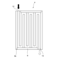
図5~図8は底部4aに形成される冷却水経路5の各種パターンを示す。
図5に示すパターンでは底部4aに底部4aの長手方向に延長する複数の同一長さの仕切り板14が同一間隔で相互に平行に配設される。各仕切り板14の両端部14a,bは底部4aの短手側両側内側面に達しない長さとされ、その両端部14a,b位置を均一に揃えて各仕切り板14が配置される。
以上の結果この図5に示すパターンではインレット接続口12から流入する冷却水は底部4aの長手側両側内側面及び短手側両側内側面に沿った分枝路5a,bと、各仕切り板14間に形成される分枝路5c内を同一方向に進行してアウトレット接続口13に達して排出される。この態様はインレット接続口12から流入してアウトレット接続口13に達して排出される。このパターンでは冷却水がインレット接続口12から流入してアウトレット接続口13に達して排出されるまでの時間が比較的に短くなることから冷却水の温度が比較的に高い場合の冷却効率向上に有効である。
5 to 8 show various patterns of the cooling water path 5 formed in the bottom portion 4a.
In the pattern shown in FIG. 5, a plurality of partition plates 14 having the same length and extending in the longitudinal direction of the bottom portion 4a are arranged parallel to each other at the same intervals. Both ends 14a and 14b of each partition plate 14 are set so as not to reach both inner surfaces on the short side of the bottom portion 4a.
As a result of the above, in the pattern shown in FIG. It advances in the same direction through the branch passage 5c formed between them, reaches the outlet connection port 13, and is discharged. In this mode, it flows in from the inlet connection port 12, reaches the outlet connection port 13, and is discharged. In this pattern, the cooling water flows in from the inlet connection port 12, reaches the outlet connection port 13, and is discharged from the outlet connection port 13 in a relatively short time. It is valid.

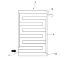
図6に示すパターンでは図5のパターンと同様に底部4aに底部4aの長手方向に延長する複数の同一長さの仕切り板14が同一間隔で相互に平行に配設される。しかし各仕切り板14の両端部14a,bのうち一端の14a若しくは14bは底部4aの短手側両側内側面の一方に達し、当接し、他端は短手側両側内側面の他方に達っせず、当接しない態様で、複数の同一長さの仕切り板14が交互に配置される。その結果この図6に示すパターンではインレット接続口12から流入する冷却水の底部4aの長手側両側内側面に沿った分枝路5aは形成されるものの短手側両側内側面に沿った状態で延びる分枝路は形成されない。
以上の結果、この図6に示すパターンでは図5に示すパターンとは異なり、インレット接続口12から流入して底部4aの長手側両側内側面に沿った分枝路5aを流れる冷却水の流れを順方向の流れとすると、接続口12から流入して底部4aの長手側両側内側面に沿った分枝路5aを順方向に流れる冷却水は短手側両側内側面に到達すると仕切り板14間を逆方向に流れ、さらに反対側の短手側両側内側面に到達すると仕切り板14間を再度順方向に流れ、その順方向の流れと逆方向の流れを交互に反復し、蛇行しながらアウトレット接続口13に達して排出される。このパターンでは冷却水がインレット接続口12から流入してアウトレット接続口13に達して排出されるまでの時間が比較的に長くなることから冷却水の温度が比較的に低い場合の冷却効率向上に有効である。
In the pattern shown in FIG. 6, a plurality of partition plates 14 having the same length and extending in the longitudinal direction of the bottom portion 4a are arranged parallel to each other at equal intervals in the same manner as in the pattern shown in FIG. However, one end 14a or 14b of both ends 14a and 14b of each partition plate 14 reaches and abuts one of the inner surfaces on both short sides of the bottom portion 4a, and the other end reaches the other inner surface on both short sides. A plurality of partition plates 14 having the same length are alternately arranged in such a manner that they do not contact each other. As a result, in the pattern shown in FIG. 6, although the branch paths 5a are formed along the inner side surfaces of the bottom portion 4a of the cooling water flowing from the inlet connection port 12, the branch paths 5a are formed along the inner side surfaces of the shorter side. No extended branches are formed.
As a result, unlike the pattern shown in FIG. 5, the pattern shown in FIG. Assuming that the cooling water flows in the forward direction, the cooling water that flows in from the connection port 12 and flows in the forward direction through the branch passages 5a along the inner surfaces on both the longitudinal sides of the bottom portion 4a reaches the inner surfaces on both the lateral sides, and flows between the partition plates 14. flow in the opposite direction, and when it reaches the inner side surfaces of the short sides on the opposite side, it flows again in the forward direction between the partition plates 14, and the forward and reverse flows are alternately repeated, meandering while the outlet It reaches the connection port 13 and is discharged. In this pattern, it takes a relatively long time for the cooling water to flow in from the inlet connection port 12, reach the outlet connection port 13, and then be discharged. It is valid.

図7に示すパターンでは底部4aに底部4aの短手方向に延長する複数の同一長さの仕切り板14が同一間隔で相互に平行に配設される。各仕切り板14の両端部14a,bは底部4aの長手側両側内側面に達しない長さとされ、その両端部14a,b位置を均一に揃えて各仕切り板14が配置される。
以上の結果この図5に示すパターンではインレット接続口12から流入する冷却水は底部4aの長手側両側内側面及び短手側両側内側面に沿った分枝路5a,bと、各仕切り板14間に形成される分枝路5c内を同一方向に進行してアウトレット接続口13に達して排出される。このパターンでは冷却水がインレット接続口12から流入してアウトレット接続口13に達して排出されるまでの時間が比較的に短くなることから冷却水の温度が比較的に高い場合の冷却効率向上に有効である。
In the pattern shown in FIG. 7, a plurality of partition plates 14 having the same length and extending in the lateral direction of the bottom portion 4a are arranged parallel to each other at the same intervals. Both ends 14a and 14b of each partition plate 14 are set so as not to reach both longitudinal side inner surfaces of the bottom portion 4a.
As a result of the above, in the pattern shown in FIG. It advances in the same direction through the branch passage 5c formed between them, reaches the outlet connection port 13, and is discharged. In this pattern, the cooling water flows in from the inlet connection port 12, reaches the outlet connection port 13, and is discharged from the outlet connection port 13 in a relatively short time. It is valid.

図8に示すパターンでは図7に示すパターンと同様に底部4aに底部4aの短手方向に延長する複数の同一長さの仕切り板14が同一間隔で相互に平行に配設される。しかし各仕切り板14の両端部14a,bのうち一端の14a若しくは14bは底部4aの長手側両側内側面の一方に達し、当接し、他端は長手側両側内側面の他方に達っせず、当接しない態様で、複数の同一長さの仕切り板14が交互に配置される。その結果この図8に示すパターンではインレット接続口12から流入する冷却水の底部4aの短手側両側内側面に沿った分枝路5aは形成されるものの長手側両側内側面に沿った状態で延びる分枝路は形成されない。
以上の結果、この図8に示すパターンでは図7に示すパターンとは異なり、インレット接続口12から流入して底部4aの短手側両側内側面に沿った分枝路5aを流れる冷却水の流れを順方向の流れとすると、接続口12から流入して底部4aの短手側両側内側面に沿った分枝路5aを順方向に流れる冷却水は長手側両側内側面に到達すると仕切り板14間を逆方向に流れ、さらに反対側の長手側両側内側面に到達すると仕切り板14間を再度順方向に流れ、その順方向の流れと逆方向の流れを交互に反復し、蛇行しながらアウトレット接続口13に達して排出される。このパターンでは冷却水がインレット接続口12から流入してアウトレット接続口13に達して排出されるまでの時間が比較的に長くなることから冷却水の温度が比較的に低い場合の冷却効率向上に有効である。
In the pattern shown in FIG. 8, as in the pattern shown in FIG. 7, a plurality of partition plates 14 having the same length and extending in the lateral direction of the bottom portion 4a are arranged parallel to each other at equal intervals. However, one end 14a or 14b of both ends 14a and 14b of each partition plate 14 reaches and abuts one of the longitudinal side inner surfaces of the bottom portion 4a, and the other end does not reach the other of the longitudinal side inner surfaces. , a plurality of partition plates 14 of the same length are alternately arranged in a non-contact manner. As a result, in the pattern shown in FIG. 8, the branch passages 5a are formed along both inner side surfaces of the bottom portion 4a of the cooling water flowing from the inlet connection port 12, but the branch passages 5a are formed along both inner side surfaces of the longer side. No extended branches are formed.
As a result, unlike the pattern shown in FIG. 7, the pattern shown in FIG. is a forward flow, the cooling water flowing from the connection port 12 and flowing forward through the branch passages 5a along the inner surfaces on both short sides of the bottom portion 4a reaches the inner surfaces on both longitudinal sides, and the partition plate 14 When it reaches the inner side surfaces on the opposite longitudinal side, it flows again in the forward direction between the partition plates 14, and the forward and reverse flows are alternately repeated, and the outlets are meandering. It reaches the connection port 13 and is discharged. In this pattern, it takes a relatively long time for the cooling water to flow in from the inlet connection port 12, reach the outlet connection port 13, and then be discharged. It is valid.

図9はさらに本発明の他の実施の形態の樹脂製モジュールケース4を示す。本実施の形態では樹脂製モジュールケース4外周にさらに冷却配管15を設けて冷却効果を増強する。冷却配管15は樹脂製モジュールケース4の成型工程において肉厚の大きい部位を予め設定し、その部分にガス射出を行うことによって空洞を生成し、その空洞を冷却媒体の流動通路、すなわち冷却配管15とする。これによって、樹脂製モジュールケース4による冷却性能をさらに向上させることができる。 FIG. 9 further shows a resin module case 4 according to another embodiment of the present invention. In this embodiment, a cooling pipe 15 is further provided around the resin module case 4 to enhance the cooling effect. In the molding process of the resin module case 4, the cooling pipe 15 is formed by preliminarily setting a portion having a large wall thickness and injecting gas into the portion to generate a cavity. and As a result, the cooling performance of the resin module case 4 can be further improved.

図10、 図11は本発明のバッテリー収納装置1の樹脂製モジュールケース4の他の形態を示す。
図10に示す樹脂製モジュールケース4はガスインジェクション成形にあたってスライド金型を用いて得られ、冷却水経路5はほとんどの領域が樹脂層によって形成され、スライド金型を用いて樹脂製モジュールケース4の短手側両側面に形成された開口部分5bに成形後にボトムパネル6を溶着して樹脂製モジュールケース4を得ることができる。その場合にボトムパネル6は両側面の2枚の同一のボトムパネル6で足りる。冷却水経路5はその長手方向を樹脂製モジュールケース4の長手方向に一致させて、順方向と逆方向とが交互に形成される蛇行する冷却水経路5となる。
10 and 11 show other forms of the resin module case 4 of the battery storage device 1 of the present invention.
The resin module case 4 shown in FIG. 10 is obtained by using a slide mold for gas injection molding. The resin module case 4 can be obtained by welding the bottom panel 6 to the openings 5b formed on both sides of the short side after molding. In that case, two identical bottom panels 6 on both sides are sufficient for the bottom panel 6 . The cooling water path 5 has its longitudinal direction aligned with the longitudinal direction of the resin module case 4 to form a meandering cooling water path 5 in which the forward direction and the reverse direction are alternately formed.

図11に示す樹脂製モジュールケース4もガスインジェクション成形にあたってスライド金型を用いて得られ、冷却水経路5はその長手方向を樹脂製モジュールケース4の短手方向に一致させて、樹脂製モジュールケース4の長手方向に蛇行して進行する冷却水経路5となる。またその開口部分5bは樹脂製モジュールケース4の長手側両側面に形成され、成形後にボトムパネル6を溶着して樹脂製モジュールケース4を得ることができる。その場合にボトムパネル6は両側面の2枚の同一のボトムパネル6で足りる。 The resin module case 4 shown in FIG. 11 is also obtained by using a slide mold for gas injection molding. A cooling water path 5 that meanders and advances in the longitudinal direction of 4 is formed. The openings 5b are formed on both longitudinal sides of the resin module case 4, and the resin module case 4 can be obtained by welding the bottom panel 6 after molding. In that case, two identical bottom panels 6 on both sides are sufficient for the bottom panel 6 .

図12(a)(b)は本発明のバッテリー収納装置1の樹脂製モジュールケース4の他の形態を示す。この実施の形態では樹脂製モジュールケース4壁面に板金プレス等によって得られた金属部品16をインサート成形し冷却効果を増強する。
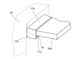
この場合にリチウムイオンバッテリー3に金属板を直接に接する構造とした場合にはショートの可能性が生じ、リチウムイオンバッテリー3がダメージを受けることがある。その場合には金属板からの放熱が出来ず、冷却性能が低くなる。そこで樹脂製モジュールケース4を射出成型する際に熱伝導率の高い銅、アルミ等の板状金属部品16をインサート成形し、樹脂製モジュールケース4内部の温度制御を向上させると共にショートの可能性を無くし冷却性能の低下を防ぐ。そのために樹脂製モジュールケース4本体部には板状金属部品16が備える係止部16aを係止させる係止孔部17が長手側両側面に形成される。さらに樹脂製モジュールケース4外側面には係止孔部17を囲む庇部17a,b,c,dが樹脂製モジュールケース4外側面の外方に延出する態様で設けられる。なお、図12中楕円破線部の庇部17a,b,c,dを図12中で拡大して示す。
板状金属部品16が備える係止部16a端部は樹脂製モジュールケース4外側に係止孔部17を介して延出し、庇部17a,b,c,dに係合する。
図13に示す様に、その樹脂製モジュールケース4の係止孔部17の開口面積は16の係止部16の断面積よりも大にされており、その結果、庇部17a,b,c,dと金属部品16の係止部16aとの間に予め間隙18を設けることができる。これによって、温度変化における樹脂部分と金属部分の線膨張の差を吸収し、製品の寸法安定性を向上させることができる。
12(a) and 12(b) show other forms of the resin module case 4 of the battery storage device 1 of the present invention. In this embodiment, a metal part 16 obtained by sheet metal pressing or the like is insert-molded on the wall surface of the resin module case 4 to enhance the cooling effect.
In this case, if the metal plate is in direct contact with the lithium ion battery 3, there is a possibility of a short circuit, and the lithium ion battery 3 may be damaged. In that case, the heat cannot be radiated from the metal plate, and the cooling performance is lowered. Therefore, when the resin module case 4 is injection molded, a plate-shaped metal part 16 made of copper, aluminum, or the like having high thermal conductivity is insert-molded to improve the temperature control inside the resin module case 4 and to reduce the possibility of short circuits. Prevents loss of cooling performance. For this purpose, locking holes 17 for locking locking portions 16a of the plate-like metal parts 16 are formed on both longitudinal sides of the main body of the resin module case 4. As shown in FIG. Further, eaves 17 a , b , c , and d surrounding the locking hole 17 are provided on the outer surface of the resin module case 4 so as to extend outward from the outer surface of the resin module case 4 . 12, the eaves 17a, b, c, and d of the elliptical broken line portion are enlarged in FIG.
The ends of the locking portions 16a of the plate-shaped metal part 16 extend outside the resin module case 4 through the locking holes 17 and engage with the eaves 17a, b, c, and d.
As shown in FIG. 13, the opening area of the locking hole portion 17 of the resin module case 4 is larger than the cross-sectional area of the locking portion 16 of the resin module case 4. , d and the engaging portion 16a of the metal part 16, a gap 18 can be provided in advance. As a result, the difference in linear expansion between the resin portion and the metal portion due to temperature changes can be absorbed, and the dimensional stability of the product can be improved.

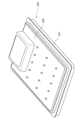
図14は本発明のバッテリー収納装置1の樹脂製モジュールケース4の他の形態を示す。樹脂製モジュールケース4を製造するにあたって予めプレス工法にて成型された熱伝導率の高い、銅、アルミ等の板状金属部品16を用意する。この板状金属部品16を配置して樹脂製モジュールケース配管カットモデル4eを脂製モジュールケース本体部4dに振動溶着して締結し、図15、図16に示す樹脂製モジュールケース4を得る。これによって板状金属部品16及び冷却水経路5の冷却媒体を介して効率よくバッテリーを冷却することを可能ならしめる。
具体的には図16に示す様に板状金属部品16はその端部が冷却水経路5に当接して冷却水経路5によって冷却されると共に金属部品16の係止部16a端部は樹脂製モジュールケース4の外側に突出して、放熱される。
FIG. 14 shows another form of the resin module case 4 of the battery storage device 1 of the present invention. In manufacturing the resin module case 4, a plate-shaped metal part 16 made of copper, aluminum, or the like, which is molded in advance by a press method and has a high thermal conductivity, is prepared. This plate-like metal part 16 is arranged, and the resin module case piping cut model 4e is vibration-welded to the fat module case main body 4d and fastened to obtain the resin module case 4 shown in FIGS. As a result, the battery can be efficiently cooled through the plate-like metal part 16 and the cooling medium of the cooling water path 5 .
Specifically, as shown in FIG. 16, the plate-like metal part 16 is cooled by the cooling water path 5 as its end abuts against the cooling water path 5, and the locking part 16a end of the metal part 16 is made of resin. It projects outside the module case 4 to dissipate heat.

以下に本発明のバッテリー収納装置1の製造方法につき説明する。
図17、図18、図19に示すように先ず樹脂射出成形によって樹脂製モジュールケース4の底部4aと側部4bとを一体に形成した本体部4cを得る。係る本体部4cには所定の射出成形金型(図示せず)を用いることによって冷却水経路5が形成される。その冷却水経路5の開口部分5bにボトムパネル6を溶着して樹脂製モジュールケース4を得ることができる。この場合に複数の開口部分5bに単一のボトムパネル6aを溶着するようにすることによって部品点数を低減しボトムパネル6の溶着工数を削減することができる。また冷却水経路5の長手方向端部に開口部分5bが形成される様にすることによって溶着工程を簡易化することができる。
A method for manufacturing the battery storage device 1 of the present invention will be described below.
As shown in FIGS. 17, 18 and 19, first, a body portion 4c is obtained by integrally forming the bottom portion 4a and the side portions 4b of the resin module case 4 by resin injection molding. A cooling water path 5 is formed in the body portion 4c by using a predetermined injection mold (not shown). The resin module case 4 can be obtained by welding the bottom panel 6 to the opening 5 b of the cooling water path 5 . In this case, by welding a single bottom panel 6a to the plurality of openings 5b, the number of parts can be reduced and the man-hours for welding the bottom panel 6 can be reduced. Further, by forming the opening 5b at the end of the cooling water path 5 in the longitudinal direction, the welding process can be simplified.

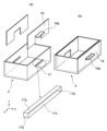
図20は本発明のバッテリー収納装置1の製造方法の他の形態を示す。図20に示すように予め樹脂製モジュールケース本体部4dと樹脂製モジュールケース配管カットモデル4eを射出成型する。その後に樹脂製モジュールケース配管カットモデル4eを脂製モジュールケース本体部4dに振動溶着して図21に示す樹脂製モジュールケース4を得る。係る態様によって樹脂製モジュールケース4の底部冷却部の冷却効果を最適化するよう制御する。すなわち樹脂製モジュールケース本体部4dを同一の態様の部品として、一方樹脂製モジュールケース配管カットモデル4eによって多様な冷却媒体の流路を形成できるようにする。これによって樹脂製モジュールケース配管カットモデル4eによって得られる冷却媒体の流路の最適化が容易となる。そのように最適化した樹脂製モジュールケース配管カットモデル4eを振動溶着により締結し、得られる樹脂製モジュールケース4によって適切な冷却効果が得られるように制御することが可能となる。 FIG. 20 shows another embodiment of the manufacturing method of the battery storage device 1 of the present invention. As shown in FIG. 20, a resin module case main body 4d and a resin module case piping cut model 4e are injection-molded in advance. After that, the resin module case piping cut model 4e is vibration welded to the resin module case main body 4d to obtain the resin module case 4 shown in FIG. Control is performed so as to optimize the cooling effect of the bottom cooling portion of the resin module case 4 in this manner. That is, the resin module case main body 4d is used as a component of the same aspect, while the resin module case piping cut model 4e is used to form various cooling medium flow paths. This facilitates optimization of the cooling medium flow path obtained by the resin module case piping cut model 4e. The resin module case piping cut model 4e optimized in this way can be fastened by vibration welding, and the obtained resin module case 4 can be controlled to obtain an appropriate cooling effect.

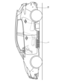
図22は本発明に係るバッテリー収納装置1を備える電動移動体としての自動車19を示す。この自動車19ではバッテリー収納装置1が自動車19の駆動力を生じるモータに電力を供給するように配置される。この場合にバッテリー収納装置1は自動車19の全高の半分の高さより下方に配置される。自動車19は電気自動車又はハイブリッド車又はPHEV又はFHEVである。
本発明に係るバッテリー収納装置1によれば従来の収納装置に比べ高さが低減されているため以上の自動車19はその全高が低減されている。
その結果、自動車19は前面投影面積を低減して空気抵抗係数(Cd=Contance drag) X 前面投影面積によって求められる空気抵抗を低くすることを可能として、電費向上を可能としている。しかも全高が低くかつバッテリー収納装置1は自動車19の全高の半分の高さより下方に配置されることも相まって重心高が低減され操舵性能が向上されている。特に電気自動車又はハイブリッド車はトルクが大きいので車重を下げることにもまして空気抵抗を下げた方が電費の抑制となるため空力性能の向上は非常に重要となる。
FIG. 22 shows an automobile 19 as an electric vehicle provided with the battery storage device 1 according to the present invention. In this motor vehicle 19, the battery storage device 1 is arranged to supply power to the motor that produces the driving force of the motor vehicle 19. As shown in FIG. In this case, the battery storage device 1 is arranged below half the height of the vehicle 19 . The vehicle 19 is an electric vehicle or hybrid vehicle or PHEV or FHEV.
According to the battery storage device 1 according to the present invention, the height is reduced as compared with the conventional storage device, so the vehicle 19 has a reduced overall height.
As a result, the frontal projected area of the automobile 19 can be reduced to lower the air resistance calculated by the coefficient of air resistance (Cd=Contance drag) x the frontal projected area, thereby improving the electric power consumption. Moreover, the overall height is low and the battery storage device 1 is arranged below half the overall height of the automobile 19, so that the height of the center of gravity is reduced and the steering performance is improved. In particular, an electric vehicle or a hybrid vehicle has a large torque. Therefore, it is very important to improve the aerodynamic performance because the reduction of the air resistance is more important than the reduction of the weight of the vehicle.

本発明に係るバッテリー収納装置1を備える電動移動体は空中飛翔体である航空機若しくは水上又は水中を移動する船体とすることもできる。
さらに本発明に係るバッテリー収納装置1を備える電動移動体は地上に設置された軌道上を移動する電車とすることもできる。
The electric vehicle equipped with the battery storage device 1 according to the present invention can also be an aircraft, which is an aerial flying object, or a hull that moves on or under water.
Furthermore, the electric vehicle provided with the battery storage device 1 according to the present invention can also be a train that moves on a track installed on the ground.

1・・・バッテリー収納装置、3・・・リチウムイオンバッテリー、2・・・バッテリーケース、4・・・樹脂製モジュールケース、5・・・冷却水経路、6・・・ボトムパネル、9・・・セパレータ。 DESCRIPTION OF SYMBOLS 1... Battery housing device 3... Lithium ion battery 2... Battery case 4... Resin module case 5... Cooling water path 6... Bottom panel 9... • Separator.

Claims (30)

バッテリーケースと、そのバッテリーケースに収納されてバッテリーを収納可能にされたモジュールケースとを備えるバッテリー収納装置において、前記モジュールケースに温度調整液体経路が形成されてなることを特徴とするバッテリー収納装置。 1. A battery storage device comprising a battery case and a module case that is housed in the battery case and capable of storing a battery, wherein the module case is formed with a temperature-adjusting liquid path. バッテリーケースと、そのバッテリーケースに収納されてバッテリーを収納可能にされたモジュールケースとを備えるバッテリー収納装置において、前記モジュールケースと一体な温度調整液体経路を有することを特徴とするバッテリー収納装置。 A battery storage device comprising a battery case and a module case that is housed in the battery case and capable of housing a battery, wherein the battery storage device is characterized by having a temperature control liquid path integrated with the module case. バッテリーケースと、そのバッテリーケースに収納されてバッテリーを収納可能にされたモジュールケースとを備えるバッテリー収納装置において、前記モジュールケース自体が温度調整液体経路を有することを特徴とするバッテリー収納装置。 1. A battery storage device comprising a battery case and a module case that is housed in the battery case and capable of housing a battery, wherein the module case itself has a temperature control liquid path. 前記モジュールケースに一体なセパレータを備え、前記セパレータを介在させて前記バッテリーを複数収納可能にされた請求項1~請求項3いずれか一に記載のバッテリー収納装置。 4. The battery storage device according to any one of claims 1 to 3, wherein a separator is provided integrally with the module case, and a plurality of the batteries can be stored with the separator interposed. 前記モジュールケースが底部と側部とを一体に形成してなり、前記底部に前記温度調整液体経路が形成された請求項1~請求項4いずれか一に記載のバッテリー収納装置。 The battery storage device according to any one of claims 1 to 4, wherein the module case is integrally formed with a bottom portion and a side portion, and the temperature control liquid path is formed in the bottom portion. 前記モジュールケースが底部と側部とを一体に形成してなり、前記側部に前記温度調整液体経路が形成された請求項1~請求項4いずれか一に記載のバッテリー収納装置。 The battery storage device according to any one of claims 1 to 4, wherein the module case is integrally formed with a bottom portion and a side portion, and the temperature control liquid path is formed in the side portion. 前記底部及び/又は側部には前記温度調整液体経路に接続するインレット接続口及びアウトレット接続口がモジュールケースと一体に形成された請求項5又は請求項6記載のバッテリー収納装置。 7. The battery storage device according to claim 5, wherein an inlet connection port and an outlet connection port connected to the temperature-adjusting liquid path are formed integrally with the module case on the bottom and/or the side. 前記モジュールケースが樹脂からなる請求項1~請求項8いずれか一に記載のバッテリー収納装置。 The battery storage device according to any one of claims 1 to 8, wherein the module case is made of resin. 前記モジュールケースが熱伝導率を向上する素材を分散した複合材からなる請求項1~請求項8いずれか一に記載のバッテリー収納装置。 The battery storage device according to any one of claims 1 to 8, wherein the module case is made of a composite material in which a material that improves thermal conductivity is dispersed. 前記モジュールケースはCNF(セルロースナノファイバー)との複合樹脂からなる請求項1~請求項9いずれか一に記載のバッテリー収納装置。 The battery storage device according to any one of claims 1 to 9, wherein the module case is made of composite resin with CNF (cellulose nanofiber). 前記バッテリーケースは炭素繊維複合樹脂からなる請求項1~請求項10のいずれか一記載のバッテリー収納装置。 The battery storage device according to any one of claims 1 to 10, wherein the battery case is made of carbon fiber composite resin. 前記温度調整液体経路が複数に分岐されて、少なくとも一対の分岐路内の温度調整液体の流れ方向が同一方向にされる請求項1~請求項11のいずれか一記載のバッテリー収納装置。 The battery storage device according to any one of claims 1 to 11, wherein the temperature-adjusting liquid path is branched into a plurality of paths, and the temperature-adjusting liquid flows in the same direction in at least one pair of branched paths. 前記温度調整液体経路が複数に分岐されて、少なくとも一対の分岐路内の温度調整液体の流れ方向が逆方向にされる請求項1~請求項12のいずれか一記載のバッテリー収納装置。 The battery storage device according to any one of claims 1 to 12, wherein the temperature-adjusting liquid path is branched into a plurality of branches, and the temperature-adjusting liquid flows in at least one pair of branched paths in opposite directions. 前記モジュールケース外周にさらに冷却配管を設けてなる請求項1~請求項13のいずれか一記載のバッテリー収納装置。 14. The battery storage device according to any one of claims 1 to 13, further comprising a cooling pipe provided around the module case. 前記モジュールケースがスライド金型を用いて成形されて、前記スライド金型によって形成された開口部分にボトムパネルを溶着してなる請求項1~請求項14のいずれか一記載のバッテリー収納装置。 The battery storage device according to any one of claims 1 to 14, wherein the module case is molded using a slide mold, and a bottom panel is welded to an opening formed by the slide mold. 前記モジュールケースの対向する2側面にボトムパネルを溶着してなる請求項1~請求項15のいずれか一記載のバッテリー収納装置。 The battery storage device according to any one of claims 1 to 15, wherein bottom panels are welded to two opposing sides of the module case. 前記モジュールケースに金属部品がインサート成形されてなる請求項1~請求項16のいずれか一記載のバッテリー収納装置。 The battery storage device according to any one of claims 1 to 16, wherein metal parts are insert-molded in said module case. 前記モジュールケース本体部には板状の前記金属部品が備える係止部を係止させる係止孔部が形成され前記金属部品を前記モジュールケース本体部に形成された係止孔部に係合させて金属部品がインサート成形されてなる請求項17に記載のバッテリー収納装置。 The module case body is formed with a locking hole for locking the locking part of the plate-like metal part, and the metal part is engaged with the locking hole formed in the module case body. 18. The battery storage device according to claim 17, wherein the metal part is insert-molded. 前記モジュールケースの係止孔部の開口面積は前記金属部品の係止部の断面積よりも大にされる請求項18に記載のバッテリー収納装置。 19. The battery storage device according to claim 18, wherein the opening area of the locking hole of the module case is larger than the cross-sectional area of the locking portion of the metal part. 前記金属部品の端部を前記温度調整液体経路に当接させ、かつ前記係止部端部はモジュールケースの外側に突出させた請求項18又は請求項19に記載のバッテリー収納装置。 20. The battery storage device according to claim 18, wherein an end portion of said metal part is brought into contact with said temperature-adjusting liquid path, and an end portion of said engaging portion protrudes outside the module case. 請求項1~請求項20のいずれか一記載のバッテリー収納装置の製造方法であって、 樹脂射出成形によってモジュールケースの底部と側部とを一体に形成し、温度調整液体経路が形成された本体部を得る工程と、前記温度調整液体経路の開口部分にボトムパネルを溶着して前記モジュールケースを得る工程とよりなることを特徴とするバッテリー収納装置の製造方法。 21. The method of manufacturing the battery storage device according to any one of claims 1 to 20, wherein the bottom and side portions of the module case are integrally formed by resin injection molding, and the main body is formed with a temperature control liquid path. and obtaining the module case by welding a bottom panel to the opening of the temperature adjusting liquid passage. 複数の前記開口部分に単一のボトムパネルを溶着する請求項21記載のバッテリー収納装置の製造方法。 22. The method of claim 21, wherein a single bottom panel is welded to the plurality of openings. 請求項1~請求項19のいずれか一記載のバッテリー収納装置の製造方法であって、予めモジュールケース本体部とモジュールケース配管カットモデルとを射出成型する工程と、前記モジュールケース配管カットモデルを前記モジュールケース本体部に振動溶着する工程とよりなることを特徴とするバッテリー収納装置の製造方法。 20. The method of manufacturing a battery storage device according to any one of claims 1 to 19, comprising a step of injection-molding a module case main body portion and a module case pipe cut model in advance; A method of manufacturing a battery storage device, comprising: a step of vibration welding to a module case main body. 同一の前記モジュールケース本体部に対し、前記モジュールケース配管カットモデルに2種類以上の冷却媒体の流路を形成できるようにした請求項23記載のバッテリー収納装置の製造方法。 24. The method of manufacturing a battery storage device according to claim 23, wherein two or more coolant flow paths can be formed in said module case piping cut model for the same module case main body. 請求項1~請求項19のいずれか一記載のバッテリー収納装置を備える電動移動体であって、前記バッテリー収納装置が移動体の駆動力を生じるモータに電力を供給するようにしてなる電動移動体。 An electric vehicle comprising the battery storage device according to any one of claims 1 to 19, wherein the battery storage device supplies electric power to a motor that generates driving force for the vehicle. . 請求項25に記載される電動移動体であって、前記バッテリー収納装置が移動体本体の全高の半分の高さより下方に配置される電動移動体。 26. The electric vehicle according to claim 25, wherein the battery storage device is arranged below half the height of the body of the vehicle. 前記電動移動体が地上を走行する電気自動車又はハイブリッド車又はPHEV又はFHEVである請求項25又は請求項26記載の電動移動体。 27. The electric vehicle according to claim 25 or 26, wherein the electric vehicle is an electric vehicle, hybrid vehicle, PHEV, or FHEV that runs on the ground. 前記電動移動体が空中飛翔体である請求項25又は請求項26記載の電動移動体。 27. The electric vehicle according to claim 25 or 26, wherein the electric vehicle is an aerial flying object. 前記電動移動体が水上又は水中を移動する船体である請求項25又は請求項26記載の電動移動体。 27. The electric vehicle according to claim 25 or 26, wherein the electric vehicle is a ship that moves on water or in water. 前記電動移動体が軌道上を移動する電車である請求項25又は請求項26記載の電動移動体。 27. The electric vehicle according to claim 25 or 26, wherein the electric vehicle is a train that moves on a track.
JP2021190710A 2021-11-25 2021-11-25 Battery storage device, manufacturing method for battery storage device, and electric vehicle equipped with the battery storage device Active JP7766477B2 (en)

Priority Applications (2)

Application Number Priority Date Filing Date Title
JP2021190710A JP7766477B2 (en) 2021-11-25 2021-11-25 Battery storage device, manufacturing method for battery storage device, and electric vehicle equipped with the battery storage device
JP2025181797A JP2026016620A (en) 2021-11-25 2025-10-28 Battery storage device, manufacturing method for battery storage device, and electric vehicle equipped with the battery storage device

Applications Claiming Priority (1)

Application Number Priority Date Filing Date Title
JP2021190710A JP7766477B2 (en) 2021-11-25 2021-11-25 Battery storage device, manufacturing method for battery storage device, and electric vehicle equipped with the battery storage device

Related Child Applications (1)

Application Number Title Priority Date Filing Date
JP2025181797A Division JP2026016620A (en) 2021-11-25 2025-10-28 Battery storage device, manufacturing method for battery storage device, and electric vehicle equipped with the battery storage device

Publications (2)

Publication Number Publication Date
JP2023077458A true JP2023077458A (en) 2023-06-06
JP7766477B2 JP7766477B2 (en) 2025-11-10

Family

ID=86622633

Family Applications (2)

Application Number Title Priority Date Filing Date
JP2021190710A Active JP7766477B2 (en) 2021-11-25 2021-11-25 Battery storage device, manufacturing method for battery storage device, and electric vehicle equipped with the battery storage device
JP2025181797A Pending JP2026016620A (en) 2021-11-25 2025-10-28 Battery storage device, manufacturing method for battery storage device, and electric vehicle equipped with the battery storage device

Family Applications After (1)

Application Number Title Priority Date Filing Date
JP2025181797A Pending JP2026016620A (en) 2021-11-25 2025-10-28 Battery storage device, manufacturing method for battery storage device, and electric vehicle equipped with the battery storage device

Country Status (1)

Country Link
JP (2) JP7766477B2 (en)

Citations (6)

* Cited by examiner, † Cited by third party
Publication number Priority date Publication date Assignee Title
JP2012256468A (en) * 2011-06-08 2012-12-27 Honda Motor Co Ltd Power supply device for vehicle
JP2013187010A (en) * 2012-03-07 2013-09-19 Toyota Motor Corp Power storage device
JP2016511509A (en) * 2013-06-07 2016-04-14 エルジー・ケム・リミテッド Battery pack with improved safety against outflow of liquid refrigerant
JP2019016596A (en) * 2017-07-05 2019-01-31 株式会社イノアックコーポレーション Battery case for vehicle
JP2019106283A (en) * 2017-12-12 2019-06-27 本田技研工業株式会社 Vehicle battery unit
JP2019114512A (en) * 2017-12-26 2019-07-11 株式会社豊田自動織機 Power storage device

Patent Citations (6)

* Cited by examiner, † Cited by third party
Publication number Priority date Publication date Assignee Title
JP2012256468A (en) * 2011-06-08 2012-12-27 Honda Motor Co Ltd Power supply device for vehicle
JP2013187010A (en) * 2012-03-07 2013-09-19 Toyota Motor Corp Power storage device
JP2016511509A (en) * 2013-06-07 2016-04-14 エルジー・ケム・リミテッド Battery pack with improved safety against outflow of liquid refrigerant
JP2019016596A (en) * 2017-07-05 2019-01-31 株式会社イノアックコーポレーション Battery case for vehicle
JP2019106283A (en) * 2017-12-12 2019-06-27 本田技研工業株式会社 Vehicle battery unit
JP2019114512A (en) * 2017-12-26 2019-07-11 株式会社豊田自動織機 Power storage device

Also Published As

Publication number Publication date
JP7766477B2 (en) 2025-11-10
JP2026016620A (en) 2026-02-03

Similar Documents

Publication Publication Date Title
US11247528B2 (en) Six-way valve and vehicle thermal management system having the same
US10734693B2 (en) Cell module for electric and hybrid vehicles
KR102269221B1 (en) Electric vehicle battery cooling system
US20220332162A1 (en) Integrated thermal management module for vehicle
JP2005349955A (en) Cooling structure of power storage mechanism
KR102691860B1 (en) Battery housing for battery module of a traction battery of a motor vehicle
JP2006179190A (en) Automotive battery pack
US20250220865A1 (en) Cooling module
JP2016091951A (en) Battery pack
JP7507538B2 (en) Vehicle and battery pack
KR20180085534A (en) Heat exchanger for battery and fuel cell stack
JP2024172114A (en) Vehicle Drive Unit
CN115702605A (en) Cooling system for electric vehicle
EP3579322B1 (en) Battery-cooling device for vehicle and manufacturing method of same
JP2023077458A (en) BATTERY STORAGE DEVICE, METHOD OF MANUFACTURING BATTERY STORAGE DEVICE, AND ELECTRIC MOVING BODY INCLUDING THIS BATTERY STORAGE DEVICE
JP7478922B2 (en) Vehicle and battery pack
CN114374020B (en) Battery pack and vehicle with same
CN216648494U (en) Box structure, battery and electric device
WO2024225210A1 (en) Vehicle drive device
CN119217925B (en) Thermal management integrated module and vehicle
CN223598808U (en) Radiator mounting structure and vehicle
US20230411727A1 (en) Battery pack including a thermal management assembly and a vehicle
CN224111415U (en) Electric drive controller and new energy vehicles
CN223014355U (en) A water cooling structure for automobile
CN119217925A (en) Thermal management integrated modules and vehicles

Legal Events

Date Code Title Description
A621 Written request for application examination

Free format text: JAPANESE INTERMEDIATE CODE: A621

Effective date: 20241022

A977 Report on retrieval

Free format text: JAPANESE INTERMEDIATE CODE: A971007

Effective date: 20250807

A131 Notification of reasons for refusal

Free format text: JAPANESE INTERMEDIATE CODE: A131

Effective date: 20250918

A521 Request for written amendment filed

Free format text: JAPANESE INTERMEDIATE CODE: A523

Effective date: 20250919

TRDD Decision of grant or rejection written
A01 Written decision to grant a patent or to grant a registration (utility model)

Free format text: JAPANESE INTERMEDIATE CODE: A01

Effective date: 20251006

A61 First payment of annual fees (during grant procedure)

Free format text: JAPANESE INTERMEDIATE CODE: A61

Effective date: 20251028

R150 Certificate of patent or registration of utility model

Ref document number: 7766477

Country of ref document: JP

Free format text: JAPANESE INTERMEDIATE CODE: R150