JP2023075813A - Storage device and image forming device - Google Patents
Storage device and image forming device Download PDFInfo
- Publication number
- JP2023075813A JP2023075813A JP2021188952A JP2021188952A JP2023075813A JP 2023075813 A JP2023075813 A JP 2023075813A JP 2021188952 A JP2021188952 A JP 2021188952A JP 2021188952 A JP2021188952 A JP 2021188952A JP 2023075813 A JP2023075813 A JP 2023075813A
- Authority
- JP
- Japan
- Prior art keywords
- storage
- medium
- main body
- elastic member
- pulled out
- Prior art date
- Legal status (The legal status is an assumption and is not a legal conclusion. Google has not performed a legal analysis and makes no representation as to the accuracy of the status listed.)
- Granted
Links
Images


Classifications
-
- B—PERFORMING OPERATIONS; TRANSPORTING
- B65—CONVEYING; PACKING; STORING; HANDLING THIN OR FILAMENTARY MATERIAL
- B65H—HANDLING THIN OR FILAMENTARY MATERIAL, e.g. SHEETS, WEBS, CABLES
- B65H5/00—Feeding articles separated from piles; Feeding articles to machines
- B65H5/006—Feeding stacks of articles to machines
-
- B—PERFORMING OPERATIONS; TRANSPORTING
- B65—CONVEYING; PACKING; STORING; HANDLING THIN OR FILAMENTARY MATERIAL
- B65H—HANDLING THIN OR FILAMENTARY MATERIAL, e.g. SHEETS, WEBS, CABLES
- B65H1/00—Supports or magazines for piles from which articles are to be separated
- B65H1/04—Supports or magazines for piles from which articles are to be separated adapted to support articles substantially horizontally, e.g. for separation from top of pile
-
- B—PERFORMING OPERATIONS; TRANSPORTING
- B65—CONVEYING; PACKING; STORING; HANDLING THIN OR FILAMENTARY MATERIAL
- B65H—HANDLING THIN OR FILAMENTARY MATERIAL, e.g. SHEETS, WEBS, CABLES
- B65H1/00—Supports or magazines for piles from which articles are to be separated
- B65H1/26—Supports or magazines for piles from which articles are to be separated with auxiliary supports to facilitate introduction or renewal of the pile
- B65H1/266—Support fully or partially removable from the handling machine, e.g. cassette, drawer
-
- G—PHYSICS
- G03—PHOTOGRAPHY; CINEMATOGRAPHY; ANALOGOUS TECHNIQUES USING WAVES OTHER THAN OPTICAL WAVES; ELECTROGRAPHY; HOLOGRAPHY
- G03G—ELECTROGRAPHY; ELECTROPHOTOGRAPHY; MAGNETOGRAPHY
- G03G15/00—Apparatus for electrographic processes using a charge pattern
- G03G15/65—Apparatus which relate to the handling of copy material
- G03G15/6502—Supplying of sheet copy material; Cassettes therefor
-
- B—PERFORMING OPERATIONS; TRANSPORTING
- B65—CONVEYING; PACKING; STORING; HANDLING THIN OR FILAMENTARY MATERIAL
- B65H—HANDLING THIN OR FILAMENTARY MATERIAL, e.g. SHEETS, WEBS, CABLES
- B65H2402/00—Constructional details of the handling apparatus
- B65H2402/30—Supports; Subassemblies; Mountings thereof
- B65H2402/32—Sliding support means
-
- B—PERFORMING OPERATIONS; TRANSPORTING
- B65—CONVEYING; PACKING; STORING; HANDLING THIN OR FILAMENTARY MATERIAL
- B65H—HANDLING THIN OR FILAMENTARY MATERIAL, e.g. SHEETS, WEBS, CABLES
- B65H2405/00—Parts for holding the handled material
- B65H2405/30—Other features of supports for sheets
- B65H2405/35—Means for moving support
-
- B—PERFORMING OPERATIONS; TRANSPORTING
- B65—CONVEYING; PACKING; STORING; HANDLING THIN OR FILAMENTARY MATERIAL
- B65H—HANDLING THIN OR FILAMENTARY MATERIAL, e.g. SHEETS, WEBS, CABLES
- B65H2801/00—Application field
- B65H2801/03—Image reproduction devices
- B65H2801/06—Office-type machines, e.g. photocopiers
-
- G—PHYSICS
- G03—PHOTOGRAPHY; CINEMATOGRAPHY; ANALOGOUS TECHNIQUES USING WAVES OTHER THAN OPTICAL WAVES; ELECTROGRAPHY; HOLOGRAPHY
- G03G—ELECTROGRAPHY; ELECTROPHOTOGRAPHY; MAGNETOGRAPHY
- G03G21/00—Arrangements not provided for by groups G03G13/00 - G03G19/00, e.g. cleaning, elimination of residual charge
- G03G21/16—Mechanical means for facilitating the maintenance of the apparatus, e.g. modular arrangements
- G03G21/1661—Mechanical means for facilitating the maintenance of the apparatus, e.g. modular arrangements means for handling parts of the apparatus in the apparatus
- G03G21/1695—Mechanical means for facilitating the maintenance of the apparatus, e.g. modular arrangements means for handling parts of the apparatus in the apparatus for paper transport
Landscapes
- Engineering & Computer Science (AREA)
- Mechanical Engineering (AREA)
- Physics & Mathematics (AREA)
- General Physics & Mathematics (AREA)
- Sheets, Magazines, And Separation Thereof (AREA)
- Electrophotography Configuration And Component (AREA)
Abstract
Description
本発明は、収容装置及び画像形成装置に関する。 The present invention relates to a storage device and an image forming device.
特許文献1には、給紙装置のカセット部を斜めに配し、対角線に最大サイズカセット(例えばA3)、その上下にそれよりも小さなカセットが置かれている構成が記載されている。 Japanese Patent Application Laid-Open No. 2002-200001 describes a configuration in which the cassette portion of the paper feeder is arranged obliquely, with the maximum size cassette (for example, A3) placed diagonally, and smaller cassettes placed above and below it.
本発明の目的は、ユーザが媒体を収容部に供給可能な収容装置において、収容部の両側に同じ高さで伸縮部材が取り付けられている場合と比較して、収容部の設置自由度を高くすることである。 SUMMARY OF THE INVENTION An object of the present invention is to provide a storage device in which a user can supply a medium to a storage unit, and to increase the degree of freedom in setting the storage unit compared to the case where elastic members are attached to both sides of the storage unit at the same height. It is to be.
本発明の第1態様の収容装置は、装置本体と、前記装置本体から引き出し方向に引き出されることで、ユーザが媒体を供給可能な供給位置へ移動可能な収容部であって、前記引き出し方向との交差方向において、重心位置が中心に対して一方の側面側に位置する前記収容部と、伸縮することで前記装置本体に対し前記収容部を引き出し可能に繋ぐ第1伸縮部材であって、前記交差方向において前記収容部の前記一方の側面に固定された前記第1伸縮部材と、伸縮することで前記装置本体に対し前記収容部を引き出し可能に繋ぐ第2伸縮部材であって、前記交差方向において前記収容部の他方の側面の前記第1伸縮部材よりも高い位置に固定された第2伸縮部材と、を備える。 A storage device according to a first aspect of the present invention includes a device main body, and a storage section that can be moved to a supply position where a user can supply a medium by being pulled out from the device main body in the pull-out direction. In the cross direction of the above, the center of gravity position is located on one side of the center, and a first elastic member that stretches and contracts to connect the storage portion to the apparatus body so that it can be pulled out, wherein the The first stretchable member fixed to the one side surface of the storage section in the cross direction, and the second stretchable member that stretches to connect the storage section to the apparatus main body so as to be able to be pulled out, wherein the stretchable member is the cross direction. and a second stretchable member fixed at a position higher than the first stretchable member on the other side surface of the accommodating portion.
本発明の第2態様の収容装置は、第1態様の収容装置において、前記交差方向において、前記収容部の前記第1伸縮部材取り付け側の側壁は金属により形成されており、前記収容部の前記第2伸縮部材取り付け側の側壁は樹脂により形成されている。 A storage device according to a second aspect of the present invention is the storage device according to the first aspect, wherein a side wall of the storage portion on the first elastic member attachment side of the storage portion in the cross direction is formed of metal, and the The side wall on the side where the second elastic member is attached is made of resin.
本発明の第3態様の収容装置は、第1態様または第2態様の収容装置において、前記収容部は、前記交差方向において、前記第2伸縮部材よりも前記第1伸縮部材に近い位置に、前記収容部に収容された媒体を鉛直方向上方に移動させるための移動機構を備える。 A storage device according to a third aspect of the present invention is the storage device according to the first aspect or the second aspect, wherein the storage portion is positioned closer to the first stretchable member than the second stretchable member in the cross direction, A movement mechanism is provided for moving the medium accommodated in the accommodation unit vertically upward.
本発明の第4態様の収容装置は、第1態様から第3態様のいずれか1つの態様の収容装置において、前記第2伸縮部材の耐荷重は、前記第1伸縮部材の耐荷重よりも高い。 A storage device according to a fourth aspect of the present invention is the storage device according to any one of the first to third aspects, wherein the withstand load of the second stretchable member is higher than the withstand load of the first stretchable member. .
本発明の第5態様の収容装置は、装置本体と、前記装置本体から引き出し方向に引き出されることで、ユーザが媒体を供給可能な供給位置へ移動可能な収容部と、伸縮することで前記装置本体に対し前記収容部を引き出し可能に繋ぐ第1伸縮部材であって、前記引き出し方向との交差方向において前記収容部の一方の側面に固定された前記第1伸縮部材と、伸縮することで前記装置本体に対し前記収容部を引き出し可能に繋ぐ、前記第1伸縮部材よりも耐荷重が高い第2伸縮部材であって、前記交差方向において前記収容部の他方の側面の前記第1伸縮部材よりも高い位置に固定された前記第2伸縮部材と、を備える。 A storage device according to a fifth aspect of the present invention includes a device body, a storage portion that can be moved to a supply position where a user can supply a medium by being pulled out from the device body in a pull-out direction, and A first stretchable member for connecting the housing portion to the main body so as to be able to be pulled out, the first stretchable member fixed to one side surface of the housing portion in a direction crossing the pull-out direction; A second stretchable member that connects the storage section to the device main body so as to be able to be pulled out and has a higher load capacity than the first stretchable member, the second stretchable member being located on the other side of the storage section in the cross direction. and the second telescopic member fixed at a higher position.
本発明の第6態様の収容装置は、第4態様または第5態様の収容装置において、前記第2伸縮部材の板金の枚数が、前記第1伸縮部材の板金の枚数よりも多い。 A storage device according to a sixth aspect of the present invention is the storage device according to the fourth aspect or the fifth aspect, wherein the number of metal sheets of the second elastic member is larger than the number of metal sheets of the first elastic member.
本発明の第7態様の収容装置は、第4態様から第6態様のいずれか1つの態様の収容装置において、前記交差方向において、前記第2伸縮部材の幅が、前記第1伸縮部材の幅よりも広い。 A storage device according to a seventh aspect of the present invention is the storage device according to any one of the fourth to sixth aspects, wherein the width of the second stretchable member in the cross direction is equal to the width of the first stretchable member. wider than
本発明の第8態様の収容装置は、第5態様から第7態様のいずれか1つの態様の収容装置において、前記収容部は、前記交差方向において、重心位置が中心に対して前記一方の側面側に位置する。 A storage device according to an eighth aspect of the present invention is the storage device according to any one of the fifth aspect to the seventh aspect, wherein the storage portion has a center of gravity position relative to the center in the cross direction. located on the side.
本発明の第9態様の収容装置は、第1態様から第8態様のいずれか1つの態様の収容装置において、前記収容部に収容された媒体は、前記収容部の前記一方の側面側から外部に搬送される。 A storage device according to a ninth aspect of the present invention is the storage device according to any one of the first aspect to the eighth aspect, wherein the medium stored in the storage portion is released from the one side surface of the storage portion to the outside. transported to
本発明の第10態様の収容装置は、第1態様から第9態様のいずれか1つの態様の収容装置において、前記装置本体の下面にキャスタが取り付けられており、鉛直方向において、前記収容部の下面が、前記キャスタの取付面よりも下方に位置する。 A storage device according to a tenth aspect of the present invention is the storage device according to any one of the first to ninth aspects, wherein casters are attached to the lower surface of the device main body, and the storage portion is vertically movable. The lower surface is located below the mounting surface of the caster.
本発明の第11態様の収容装置は、第10態様の収容装置において、前記収容部、前記第1伸縮部材、及び、前記キャスタが、鉛直方向において重なる位置に配置されている。 A storage device according to an eleventh aspect of the present invention is the storage device according to the tenth aspect, wherein the storage portion, the first elastic member, and the casters are arranged at positions overlapping each other in the vertical direction.
本発明の第12態様の収容装置は、第1態様から第11態様のいずれか1つの態様の収容装置において、前記装置本体から前記引き出し方向に引き出し可能な、前記収容部とは異なる、少なくとも1つ以上の他の収容部をさらに備え、全ての収容部の前記引き出し方向を向く前側面が、前記引き出し方向において略同じ位置まで引き出すことが可能なように構成されている。 A storage device according to a twelfth aspect of the present invention is the storage device according to any one of the first to eleventh aspects, wherein at least one It further comprises three or more other housing portions, and is configured such that the front side faces of all the housing portions facing the pull-out direction can be pulled out to approximately the same position in the pull-out direction.
本発明の第13態様の画像形成装置は、第1態様から第11態様のいずれか1つの態様の収容装置と、前記収容装置に収容されて搬送される媒体に画像を形成する画像形成部と、を備える。 An image forming apparatus according to a thirteenth aspect of the present invention comprises the storage device according to any one of the first to eleventh aspects, and an image forming unit configured to form an image on a medium stored in the storage device and conveyed. , provided.
本発明の第1態様の収容装置によれば、収容部の両側の同じ高さに伸縮部材を設ける場合と比較して、伸縮部材を含む収容部の設置自由度を高くすることができる。 According to the storage device of the first aspect of the present invention, compared to the case where the expansion members are provided at the same height on both sides of the storage portion, it is possible to increase the degree of freedom in installing the storage portion including the expansion members.
本発明の第2態様の収容装置によれば、第2伸縮部材取り付け側の側壁が金属により形成されている場合と比較して、第2伸縮部材に掛かる荷重を抑えることができる。 According to the storage device of the second aspect of the present invention, the load applied to the second elastic member can be suppressed compared to the case where the side wall on the side where the second elastic member is attached is made of metal.
本発明の第3態様の収容装置によれば、収容部の機能部品の配置により、第1伸縮部材側に重心を寄せることができる。 According to the accommodation device of the third aspect of the present invention, the center of gravity can be brought closer to the first elastic member side by arranging the functional parts of the accommodation portion.
本発明の第4態様の収容装置によれば、2つの伸縮部材の耐荷重が同じ、または、第1伸縮部材の耐荷重が第2伸縮部材の耐荷重よりも高い場合と比較して、第1伸縮部材を小型軽量化し易い。 According to the storage device of the fourth aspect of the present invention, compared to the case where the load resistance of the two elastic members is the same or the load resistance of the first elastic member is higher than the load resistance of the second elastic member, the 1. It is easy to reduce the size and weight of the expandable member.
本発明の第5態様の収容装置によれば、収容部の両側の同じ高さに伸縮部材を設ける場合と比較して、伸縮部材を含む収容部の設置自由度を高くすることができる。 According to the storage device of the fifth aspect of the present invention, compared to the case where the expansion members are provided at the same height on both sides of the storage portion, the installation freedom of the storage portion including the expansion members can be increased.
本発明の第6態様の収容装置によれば、第2伸縮部材の板金の枚数が、第1伸縮部材の板金の枚数と同じ、または第1伸縮部材の板金の枚数よりも少ない場合と比較して、第2伸縮部材の耐荷重を第1伸縮部材の耐荷重よりも高くし易い。 According to the storage device of the sixth aspect of the present invention, the number of sheet metals of the second elastic member is the same as the number of sheet metals of the first elastic member, or less than the number of sheet metals of the first elastic member. Therefore, it is easy to make the withstand load of the second elastic member higher than the withstand load of the first elastic member.
本発明の第7態様の収容装置によれば、第2伸縮部材の幅が、第1伸縮部材の幅と同じ、または第1伸縮部材の幅よりも狭い場合と比較して、第2伸縮部材の耐荷重を第1伸縮部材の耐荷重よりも高くし易い。 According to the housing device of the seventh aspect of the present invention, the width of the second elastic member is the same as the width of the first elastic member or narrower than the width of the first elastic member. can be made higher than that of the first elastic member.
本発明の第8態様の収容装置によれば、収容部の重心位置が中心に対して他方の側面側に位置する場合と比較して、第2伸縮部材に掛かる荷重を抑えることができる。 According to the storage device of the eighth aspect of the present invention, the load applied to the second elastic member can be suppressed compared to the case where the center of gravity of the storage portion is located on the other side of the center.
本発明の第9態様の収容装置によれば、収容部に収容された媒体が収容部の他方の側面側から外部に搬送される場合と比較して、媒体の搬送時に第2伸縮部材に掛かる荷重を抑えることができる。 According to the storage device of the ninth aspect of the present invention, compared to the case where the medium stored in the storage portion is transported to the outside from the other side surface side of the storage portion, the medium is caught on the second elastic member during transportation. load can be reduced.
本発明の第10態様の収容装置によれば、収容部の下面がキャスタの取付面よりも上方に位置する場合と比較して、収容部に媒体を収容した状態における装置全体の重心を下げることができる。 According to the storage device of the 10th aspect of the present invention, the center of gravity of the entire device can be lowered with the medium stored in the storage portion compared to the case where the lower surface of the storage portion is positioned above the mounting surface of the caster. can be done.
本発明の第11態様の収容装置によれば、収容部、第1伸縮部材、及び、キャスタが、鉛直方向において異なる位置に配置されている場合と比較して、収容部に媒体を収容した状態における装置全体の重心を下げることができる。 According to the storage device of the eleventh aspect of the present invention, the medium is stored in the storage section compared to the case where the storage section, the first elastic member, and the casters are arranged at different positions in the vertical direction. The center of gravity of the entire device can be lowered.
本発明の第12態様の収容装置によれば、複数の収容部を備えた場合に、全ての収容部を引き出した状態で各収容部の前側面が異なる位置となる場合と比較して、全ての収容部を引き出した状態での安全性を向上させることができる。 According to the storage device of the twelfth aspect of the present invention, when a plurality of storage portions are provided, compared to the case where the front side surface of each storage portion is in a different position when all the storage portions are pulled out, all the storage portions are It is possible to improve safety in a state in which the housing portion of the housing is pulled out.
本発明の第13態様の画像形成装置によれば、上記収容装置を備えていない場合と比較して、画像形成装置に媒体を供給する際に必要とされる範囲を小さくすることができる。 According to the image forming apparatus of the thirteenth aspect of the present invention, it is possible to reduce the range required for supplying media to the image forming apparatus as compared with the case where the storage device is not provided.
本発明の実施形態に係る収容装置、及び画像形成装置の一例を図1~図10に従って説明する。各図に示す矢印Hは鉛直方向であって装置上下方向を示し、矢印Dは水平方向であって装置奥行方向を示し、矢印Wは水平方向であって装置幅方向を示す。 An example of an accommodation device and an image forming device according to an embodiment of the present invention will be described with reference to FIGS. 1 to 10. FIG. The arrow H shown in each figure is vertical and indicates the vertical direction of the device, the arrow D is horizontal and indicates the depth direction of the device, and the arrow W is horizontal and indicates the width direction of the device.
(画像形成装置10の全体構成)
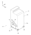
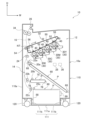
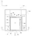
図1及び図2に示すように、画像形成装置10は、電子写真方式によりトナー画像を形成する画像形成部12と、搬送経路16に沿って媒体Pを搬送する搬送部14及び媒体Pを収容する収容部60、70、80を有する収容装置110と、を備えている。さらに、画像形成装置10は、各部を制御する制御部28と、商用主電源の電力を各部へ供給する主電源36とを備えている。
(Overall Configuration of Image Forming Apparatus 10)
As shown in FIGS. 1 and 2, the
上記構成による画像形成装置10では、収容部60、70、80によって媒体Pが収容され、搬送部14によって何れかの収容部60、70、80に収容された媒体Pが搬送経路16に沿って搬送される。さらに、画像形成部12によって形成されたトナー画像が、搬送される媒体Pに形成され、トナー画像が形成された媒体Pは、装置本体10aの外部へ排出される。
In the
〔画像形成部12〕
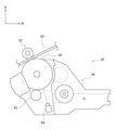
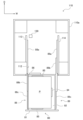
図2に示すように、画像形成部12は、各色のトナー画像を夫々形成する複数のトナー画像形成部30と、トナー画像形成部30で形成されたトナー画像を媒体Pに転写する転写部32とを備えている。さらに、画像形成部12は、転写部32によって媒体Pに転写されたトナー画像を媒体Pに定着する定着装置34を備えている。
[Image forming unit 12]
As shown in FIG. 2, the
-トナー画像形成部30-
トナー画像形成部30は、色ごとにトナー画像を形成するように複数備えられている。本実施形態では、イエロー(Y)、マゼンタ(M)、シアン(C)、ブラック(K)の計4色のトナー画像形成部30が設けられている。なお、以後の説明では、イエロー(Y)、マゼンタ(M)、シアン(C)、及びブラック(K)を区別する必要が無い場合は、符号に付するY、M、C、及びKを省略する。
- Toner image forming unit 30 -
A plurality of toner
図3に示すように、各色のトナー画像形成部30は、用いるトナーを除き基本的に同様に構成されており、回転する円筒状の像保持体40と、像保持体40を帯電する帯電器42とを備えている。さらに、トナー画像形成部30は、帯電した像保持体40に露光光を照射して静電潜像を形成する露光装置44と、トナーを含んだ現像剤Gで静電潜像をトナー画像として現像する現像装置46とを備えている。これにより、各色のトナー画像形成部30は、各色の画像を、各色のトナーを用いて形成するようになっている。
As shown in FIG. 3, the toner
また、図2に示すように、各色の像保持体40は、周回移動する転写ベルト50(詳細は後述)に接触している。そして、転写ベルト50の周回方向(図2中矢印参照)にいて、上流側からイエロー(Y)、マゼンタ(M)、シアン(C)、及びブラック(K)のトナー画像形成部30が、この順番に並んで配置されている。
Further, as shown in FIG. 2, each
-転写部32-
図2に示すように、転写部32は、転写ベルト50と、転写ベルト50を挟んで各色の像保持体40の反対側に夫々配置され、各色の像保持体40に形成されたトナー画像を転写ベルト50に転写する一次転写ロール52とを備えている。
- Transfer section 32 -
As shown in FIG. 2, the
また、転写部32は、転写ベルト50が巻き掛けられた巻掛ロール56と、転写ベルト50が巻き掛けられ、転写ベルト50に回転力を伝達する駆動ロール58とを備えている。これにより、転写ベルト50は、図中矢印方向に周回するようになっている。
The
さらに、転写部32は、転写ベルト50を挟んで巻掛ロール56の反対側に配置され、転写ベルト50上に転写されたトナー画像を媒体Pに転写する二次転写ロール54を備えている。そして、二次転写ロール54と転写ベルト50との間には、媒体Pにトナー画像を転写する転写ニップNTが形成されている。
Further, the
この構成において、イエロー(Y)、マゼンタ(M)、シアン(C)、及びブラック(K)の順番で、転写ベルト50上にトナー画像が一次転写ロール52によって一次転写される。一方、転写ベルト50と二次転写ロール54との間に挟まれて搬送される媒体Pに、二次転写ロール54によって転写ベルト50からトナー画像が転写される。さらに、トナー画像が転写された媒体Pは、定着装置34に向けて搬送される。
In this configuration, toner images are primarily transferred onto the
-定着装置34-
図2に示すように、定着装置34は、媒体Pの搬送方向において転写ニップNTの下流側に配置されている。定着装置34は、媒体Pに転写されたトナー画像を加熱、加圧して媒体Pに定着させる。
- Fixing device 34 -
As shown in FIG. 2, the fixing
〔収容装置110〕
図2に示すように、収容装置110は、画像形成装置10の下方部分に配置されており、媒体Pを収容する3個の収容部60、70、80と、媒体Pを搬送する搬送部14とを備えている。そして、最も上方に配置された収容部60は、水平方向に対して傾斜している。なお、収容装置110については、詳細を後述する。
[Accommodation device 110]
As shown in FIG. 2, the
〔制御部28、主電源36〕
制御部28、及び主電源36は、傾斜された収容部60と画像形成部12との間に形成された三角領域に配置されている。
[
The
(要部構成)
次に、収容装置110について説明する。図1及び図2に示されるように、収容装置110は、画像形成装置10の下方部分に配置されている。なお、収容装置110の装置本体110aは、画像形成装置10の装置本体10aと一体的に形成されている。
(main part configuration)
Next, the
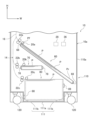
この収容装置110は、図4に示されるように、装置本体110aと、媒体Pを収容する収容部60と、媒体Pを収容する収容部70と、媒体Pを収容する収容部80とを備えている。また、収容装置110は、収容部60を装置奥行方向Dに移動可能とするスライドレール68と、収容部70を装置奥行方向Dに移動可能とするスライドレール78と、収容部80を装置奥行方向Dに移動可能とするスライドレール88とを備えている。そして、収容部60、収容部70、及び収容部80は、この順番で上方から下方へ並んでいる。
As shown in FIG. 4, the
本実施形態では、一例として、収容部60は、主にA3サイズの媒体Pを収容し、A3サイズの媒体Pが、収容部60に収容可能な媒体Pの最大サイズである。また、収容部70は、主にハガキサイズの媒体Pを収容し、ハガキサイズの媒体Pが、収容部70に収容可能な媒体Pの最大サイズである。収容部80は、主にA4サイズの媒体Pを収容し、A4サイズの媒体Pが、収容部80に収容可能な媒体Pの最大サイズである。
In the present embodiment, as an example, the
また、本実施形態では、一例として、収容部60は200枚の媒体Pを収容可能とし、収容部70は100枚の媒体Pを収容可能とし、収容部80は1000枚の媒体Pを収容可能としている。この画像形成装置10では、A4サイズの媒体Pの消費量が最も多くなることを想定している。つまり、最も消費量の多い媒体Pを収容する収容部80の収容可能な枚数が、収容部60の収容可能な枚数及び収容部70の収容可能枚数と比して多くされている。
In this embodiment, as an example, the
収容装置110の下面111の四隅には、キャスタ120が取り付けられている。収容装置110の下面111におけるキャスタ120の取付面111bは、装置上下方向Hにおいて、下面111の中心部分111aよりも高い位置に構成されている。
〔搬送部14〕
搬送部14は、図2に示されるように、収容部60に収容された媒体Pを搬送経路16へ送り出す送出ロール20aと、送出ロール20aによって送り出された媒体Pの重送を防止する防止ロール22aとを備えている。
[Conveyor 14]
As shown in FIG. 2, the
また、搬送部14は、収容部70に収容された媒体Pを搬送経路16へ送り出す送出ロール20bと、送出ロール20bによって送り出された媒体Pの重送を防止する防止ロール22bとを備えている。
The
さらに、搬送部14は、収容部80に収容された媒体Pを搬送経路16へ送り出す送出ロール20cと、送出ロール20cによって送り出された媒体Pの重送を防止する防止ロール22cとを備えている。
Further, the
また、搬送部14は、媒体Pの搬送方向において、防止ロール22a、22b、22cの下流側に配置され、転写ニップNTへ送り出す媒体Pのタイミングを調整する調整ロール24を備えている。さらに、搬送部14は、定着装置34によってトナー画像が定着された媒体Pを装置本体10aの外部へ排出する排出ロール26を備えている。
The
〔収容部60、スライドレール68〕
図4に示すように、収容部60は、上方が開放された箱状とされており、装置本体110a内で媒体を収容する。収容部60は、本発明の技術における他の収容部である。一対のスライドレール68は、収容部60の装置幅方向Wの両端に夫々取り付けられている。スライドレール68は、アウターメンバー、中間メンバー、及びインナーメンバーを備えており、アウターメンバーが、装置本体110aに取り付けられ、インナーメンバーが収容部60に取り付けられている。
[Accommodating
As shown in FIG. 4, the
これにより、ユーザが装置本体110aに対して装着された収容部60を装置奥行方向Dの手前側に引き出すと、収容部60は、スライドレール68に案内されて、装置本体110aに対して離脱される。また、ユーザが装置本体110aに対して離脱された収容部60を装置奥行方向Dの奥側に押し込むと、収容部60は、スライドレール68に案内されて、装置本体110aに対して装着される。
Accordingly, when the user pulls out the
また、収容部60は、図4に示されるように、装置本体110aに対して装着された状態、及び装置本体110aに対して離脱された状態で、装置奥行方向Dから見て、装置幅方向の一端(図中左側の端部)と他端との上下位置が異なるように水平方向に対して傾斜している。具体的には、収容部60は、装置奥行方向Dから見て、装置幅方向の一端が他端に対して上方となるように水平方向に対して傾斜している。ここで、一端、他端とは、収容部60の一部であって、装置幅方向で最も離れた2点の一方、又は他方である。
Further, as shown in FIG. 4, the
収容部60が装置本体110aに対して装着された状態で、収容部60に収容された媒体Pが搬送部14によって搬送可能とされる。換言すれば、装置本体110aに対して装着された収容部60は、収容された媒体Pを搬送可能とする搬送位置に位置している。
The medium P accommodated in the
一方、ユーザが装置本体110aに対して装着された収容部60を装置奥行方向Dの手前側に引き出すと、収容部60は、スライドレール68に案内されて、図示せぬストッパ―に当たって停止し、装置本体110aに対して離脱される。また、ユーザが装置本体110aに対して離脱された収容部60を装置奥行方向Dの奥側に押し込むと、収容部60は、スライドレール68に案内されて、装置本体110aに対して装着される。離脱とは、収容部60へ媒体Pを収容可能な状態である。本実施形態においては、収容部60が装置本体110aに対して離脱された状態とは、収容部60が装置本体110aから取り外されておらず、装置本体110aに支持されている状態であって、収容部60へ媒体Pを収容可能な状態である。
On the other hand, when the user pulls out the
そして、収容部60が装置本体110aに対して離脱された状態で、収容部60の上方が開放され、媒体Pを収容部60に供給可能とされる。換言すれば、装置本体110aに対して離脱された収容部60は、媒体Pを収容部60に供給可能とする供給位置に位置している。
Then, in a state in which the containing
〔収容部70、スライドレール78〕
図4に示すように、収容部70は、上方が開放された箱状とされており、装置本体110a内で媒体を収容する。収容部70は、本発明の技術における他の収容部である。一対のスライドレール78は、収容部70の装置幅方向Wの両端に夫々取り付けられている。
[Accommodating
As shown in FIG. 4, the
スライドレール78は、アウターメンバー、中間メンバー、及びインナーメンバーを備えており、アウターメンバーが、装置本体110aに取り付けられ、インナーメンバーが収容部70に取り付けられている。
The
これにより、ユーザが装置本体110aに対して装着された収容部70を装置奥行方向Dの手前側に引き出すと、収容部70は、スライドレール78に案内されて、装置本体110aに対して離脱される。また、ユーザが装置本体110aに対して離脱された収容部70を装置奥行方向Dの奥側に押し込むと、収容部70は、スライドレール78に案内されて、装置本体110aに対して装着される。
As a result, when the user pulls out the
また、収容部70は、装置本体110aに対して装着された状態、及び装置本体110aに対して離脱された状態で、装置奥行方向Dから見て、水平に配置されている。なお、本実施形態で収容部70が水平に配置されているとは、水平方向に沿って配置されていればよく、例えば、収容部70に収容された媒体Pが傾斜によって移動しない多少の傾斜を許容する状態である。
Further, the
そして、装置本体110aに対して装着された収容部70は、収容された媒体Pを搬送可能とする搬送位置に位置しており、装置本体110aに対して離脱された収容部70は、媒体Pを収容部70に供給可能とする供給位置に位置している。
The
〔収容部80、スライドレール88及び89〕
図4~図7に示すように、収容部80は、上方が開放された箱状とされており、装置本体110a内で、媒体Pを収容する。収容部80は、本発明の技術における収容部である。一対のスライドレール88及び89は、収容部80の装置幅方向Wの両端に夫々取り付けられている。スライドレール88は、装置幅方向Wにおいて収容部80の一方の側面80cに固定されている。スライドレール88は、本発明の技術における第1伸縮部材である。スライドレール89は、装置幅方向Wにおける収容部80の他方の側面80dにおいてスライドレール88よりも高い位置に固定されている。スライドレール89は、本発明の技術における第2伸縮部材である。
[Accommodating
As shown in FIGS. 4 to 7, the containing
なお、本実施形態では、装置奥行方向Dと、収容部80の引き出し方向Bは平行であり、装置奥行方向Dにおける引き出し方向B側を装置前側、装置奥行方向Dにおける引き出し方向Bと反対側を装置後側として説明する。また、装置幅方向Wは、本発明の技術における交差方向に対応する。なお、本実施形態において、装置奥行方向Dと収容部80の引き出し方向Bが平行であるとは、実質的に両者が平行であればよく、両者の角度差が±5°程度の誤差を許容する状態である。
In the present embodiment, the device depth direction D is parallel to the drawing direction B of the
収容部80は、図5に示すように収容装置110に装着された状態において、引き出し方向Bに引き出されることにより、図6に示すように収容装置110から引き出された状態となる。
When the
図5~図7に示すように、収容部80は、前面パネル81と、媒体保持部82と、媒体保持部82に取り付けられている媒体保持板83と、装置幅方向Wにおいて媒体Pの収容サイズを調整するための調整部材84と、装置奥行方向Dにおいて媒体Pの収容サイズを調整するための2つの調整部材85と、収容部80に収容された媒体Pを鉛直方向上方に移動させるための移動機構86と、を備える。
As shown in FIGS. 5 to 7, the
前面パネル81は、収容部80が収容装置110に装着された状態で、収容装置110の前面に露出するパネルであり、例えば樹脂により構成されている。
The
媒体保持部82は、媒体Pが設置される上方が開放された箱状の部材であり、媒体Pの設置面が箱状の収容部80の上面80eとなるように構成されている。媒体保持部82の側面82aのパネルは金属により形成されており、それ以外の部分82bは樹脂により形成されている。媒体保持部82の側面82aは、収容部80の一方の側面80cとなる面である。すなわち、装置幅方向Wにおいて、収容部80の一方の側面80cの側壁は金属により形成され、他方の側面80dの側壁は樹脂により形成されている。ここで、側面80cの側壁を形成する金属は、例えば、鉄、ステンレス、アルミニウム、ニッケル、マグネシウム、チタン、銅、及び、これら金属を含む合金等が挙げられる。また、側面80dの側壁を形成する樹脂は、例えば、ポリエチレン、ポリプロピレン、塩化ビニル樹脂、ABS(Acrylonitrile Butadiene Styrene)樹脂、ポリカーボネート、及び、エポキシ等が挙げられる。
The
媒体保持板83は、媒体保持部82内において媒体Pを保持する板状の部材であり、装置上下方向Hに移動可能なように、媒体保持部82に取り付けられている。
The
調整部材84は、装置幅方向Wに移動可能なように、媒体保持部82に取り付けられている。2つの調整部材85は、装置奥行方向Dにおいて、媒体Pの収容領域の中心位置を基準に対称的に連動して移動可能なように、媒体保持部82に取り付けられている。調整部材84及び2つの調整部材85は、ユーザにより手動で移動させられる。
The adjusting
移動機構86は、収容部80に収容された媒体Pを鉛直方向上方に移動させ、媒体Pを送出ロール20cに接触させるための機構であり、装置幅方向Wにおいて、スライドレール89よりもスライドレール88に近い位置に取り付けられている。
The moving
移動機構86は、例えば複数の歯車を備えた歯車機構により実現される。この移動機構86としての歯車機構は、収容部80が収容装置110に装着された状態で、装置本体110a内の駆動部130と連結する。駆動部130は、例えば、モータ等により実現される。
The moving
モータの回転軸と、歯車機構を構成する複数の歯車の回転軸は、ともに装置奥行方向Dと平行な軸となるように構成されている。また、歯車機構の回転軸の一つには、媒体保持板83がワイヤにより連結されている。収容部80が収容装置110に装着された状態で、モータにより歯車機構を回転させ、歯車機構の回転軸の一つに取り付けられたワイヤを巻き取ることにより、ワイヤに連結された媒体保持板83を、媒体Pとともに上方に移動させることができる。
The rotating shaft of the motor and the rotating shaft of a plurality of gears forming the gear mechanism are both configured to be parallel to the depth direction D of the device. A
上記の様に構成された収容部80は、装置幅方向Wにおいて、重心位置が中心CWに対して一方の側面80c側に位置するように構成されている。なお、この関係は、収容部80内に最大サイズの媒体Pを最大収容可能枚数収容した時も維持される。
The
なお、本実施形態において、装置幅方向Wにおける収容部80の中心CWとは、収容部80において前面80aのパネル及び後面80bのパネルを除く、媒体Pを収容する本体部の、装置幅方向Wにおける中心を意味する。具体的には、図7に示すように、収容部80において媒体Pを収容する本体部の幅である、側面80cから80dの間の領域R1の中心位置である。なお、本実施形態において、収容部80の本体部は、媒体保持部82により構成される。そのため、装置幅方向Wにおける収容部80の側面80c及び80dは、装置幅方向Wにおける媒体保持部82の両側面と同じである。ただし、媒体保持部82に対して他の部材が取り付けられている場合には、他の部材も含めて、装置幅方向Wにおける最も外側の位置が側面となる。従って、「装置幅方向Wにおける収容部80の中心CW」の位置は、収容部80の前面80aのパネル及び後面80bのパネルの形状及び大きさによって変化するものではない。
In the present embodiment, the center CW of the
図7に示すように、収容部80は、装置幅方向Wにおける収容部80の中心CWに対してスライドレール88側の内壁面80gに媒体Pを接触させて収容するように構成されている。媒体Pは、収容部80が収容装置110に装着された状態で、移動機構86により送出ロール20cに接触させられ、装置幅方向Wと平行な搬送方向Tに沿って、収容部80の一方の側面80c側から搬送される。
As shown in FIG. 7, the
本実施形態では、収容部80の引き出し方向Bと、媒体Pの搬送方向Tの先端側の辺Paは略平行である。収容部80の側面80cは、媒体Pの先端側の辺Paに沿って配置された面である。側面80dは、収容部80における側面80cと反対側の面である。なお、本実施形態において、収容部80の引き出し方向Bと媒体Pの搬送方向Tの先端側の辺Paが略平行であるとは、実質的に両者が平行であればよく、両者の角度差が±5°程度の誤差を許容する状態である。
In the present embodiment, the draw-out direction B of the
スライドレール88は、伸縮することで装置本体110aに対し収容部80を引き出し可能に繋ぐ第1伸縮部材の一例である。図8に示すように、スライドレール88は、アウターメンバー88a、中間メンバー88b、及びインナーメンバー88cを備えており、アウターメンバー88aが、装置本体110a内のキャスタ取付部の内側面112及びスライドレール固定部113に固定され、インナーメンバー88cが収容部80の一方の側面80cに取り付けられている。
The
アウターメンバー88a、中間メンバー88b、及びインナーメンバー88cは、それぞれ1枚の板金により構成されている。すなわち、スライドレール88は、全体として3枚の板金を備えている。スライドレール88は、スライドレール88を縮めた状態で、アウターメンバー88a内に中間メンバー88b及びインナーメンバー88cが収容されるように構成されている。
Each of the
スライドレール89は、伸縮することで装置本体110aに対し収容部80を引き出し可能に繋ぐ第2伸縮部材の一例である。図9に示すように、スライドレール89は、アウターメンバー89a、中間メンバー89b、及びインナーメンバー89cを備えており、アウターメンバー89aが、装置本体110a内のスライドレール固定部114に固定され、インナーメンバー89cが収容部80の他方の側面80dに取り付けられている。
The
アウターメンバー89a及びインナーメンバー89cは、それぞれ1枚の板金により構成されている。中間メンバー89bは、1枚の板金により形成されたインナーメンバー部89b1と、1枚の板金により形成されたアウターメンバー部89b2と、1枚の板金により形成された補強メンバー部89b3とが、一体化された形で構成されている。補強メンバー部89b3は、インナーメンバー部89b1及びアウターメンバー部89b2と平行に延び、中間メンバー89b全体の剛性を高めるための補強部材である。すなわち、スライドレール89は、全体として5枚の板金を備えている。
Each of the
スライドレール89は、スライドレール89を縮めた状態で、アウターメンバー89a内に中間メンバー89bのインナーメンバー部89b1が収容され、中間メンバー89bのアウターメンバー部89b2内にインナーメンバー89cが収容されるように構成されている。
The
スライドレール89の耐荷重は、スライドレール88の耐荷重よりも高くなるように構成されている。スライドレール89の板金の枚数は、スライドレール88の板金の枚数よりも多い。また、装置幅方向Wにおいて、スライドレール89の幅W2は、スライドレール88の幅W1よりも広い。これらは、いずれもスライドレール89の耐荷重を、スライドレール88の耐荷重よりも高くするのに有利な構成である。
The withstand load of the
収容部80の下面80fは、装置上下方向Hにおいて、キャスタ120の取付面111bよりも下方に位置する。また、収容部80、スライドレール88、及び、キャスタ120が、装置上下方向Hにおいて重なる位置に配置されている。また、収容部80内に媒体Pを収容した状態では、収容部80、媒体P、スライドレール88、及び、キャスタ120が、装置上下方向Hにおいて重なる位置に配置される。
A
上記の構成により、ユーザが装置本体110aに対して装着された収容部80を引き出し方向B、すなわち装置奥行方向Dの手前側に引き出すと、収容部80は、スライドレール88及び89に案内されて、装置本体110aに対して離脱される。また、ユーザが装置本体110aに対して離脱された収容部80を装置奥行方向Dの奥側に押し込むと、収容部80は、スライドレール88及び89に案内されて、装置本体110aに対して装着される。
With the above configuration, when the user pulls out the
また、収容部80は、図4に示されるように、装置本体110aに対して装着された状態、及び装置本体110aに対して離脱された状態で、装置奥行方向Dから見て、水平に配置されている。なお、本実施形態で収容部80が水平に配置されているとは、水平方向に沿って配置されていればよく、例えば、収容部80に収容された媒体Pが傾斜によって移動しない多少の傾斜を許容する状態である。
Further, as shown in FIG. 4, the
そして、装置本体110aに対して装着された収容部80は、収容された媒体Pを搬送可能とする搬送位置に位置しており、装置本体110aに対して離脱された収容部80は、媒体Pを収容部80に供給可能とする供給位置に位置している。
The
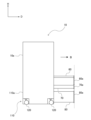
〔収容装置110の全体構成〕
上記の通り、収容装置110は、本発明の技術における収容部80に加えて、収容部80と同じ引き出し方向Bに引き出し可能な他の収容部60及び70を備えている。そして、図10に示すように、全ての収容部60、70、及び80の前面60a、70a、及び80aが、引き出し方向Bにおいて略同じ位置まで引き出すことが可能なように構成されている。なお、各収容部の前面は、収容部の引き出し方向Bを向く前側面である。なお、本実施形態において、全ての収容部60、70、及び80の前面60a、70a、及び80aが、引き出し方向Bにおいて略同じ位置まで引き出すことが可能であるとは、実質的に前面60a、70a、及び80aが同じ位置まで引き出すことが可能であればよく、各面同士の最大誤差が前面パネルの厚さ程度の1cm程度の誤差を許容する状態である。
[Overall Configuration of Storage Device 110]
As described above, the
〔収容装置110及び画像形成装置10の作用〕
以上説明したように、収容装置110においては、収容部80の装置幅方向Wの両端に夫々固定されている2本のスライドレール88及び89について、収容部80の他方の側面80dに固定されているスライドレール89は、収容部80の一方の側面80cに固定されているスライドレール88よりも高い位置に固定されている。これにより、収容部80の両側の同じ高さにスライドレールを設ける場合と比較して、重心位置の特定又は耐荷重差の特定により必要な取付強度を確保した上で、スライドレール88及び89を含む収容部80の設置自由度を高くすることができる。また、収容部80の設置自由度が高いため、収容装置110の小型化が容易になる。
[Actions of
As described above, in the
なお、収容部80の装置幅方向Wの両端において異なる高さにスライドレール88及び89を固定すると、低い位置に固定されたスライドレール88よりも、高い位置に固定されたスライドレール89に対して、荷重が掛かりやすくなる。このように、収容部80の装置幅方向Wの両端に夫々固定されている2本のスライドレール88及び89に均等に荷重が掛からず、一方の側のスライドレール89に掛かる荷重が大きくなると、収容装置110に対する収容部80の取り付け部分の耐久性が低下するおそれがある。
Note that if the slide rails 88 and 89 are fixed at different heights at both ends of the
そのため、収容部80は、装置幅方向Wにおいて、重心位置が中心CWに対して一方の側面80c側に位置するように構成されている。これにより、スライドレール89に掛かる荷重を抑えることができる。
Therefore, the
また、装置幅方向Wにおいて、収容部80の一方の側面80cの側壁は金属により形成され、他方の側面80dの側壁は樹脂により形成されている。これにより、スライドレール89に掛かる荷重を抑えることができる。
In addition, in the width direction W of the device, the side wall of one
また、移動機構86は、装置幅方向Wにおいて、スライドレール89よりもスライドレール88に近い位置に取り付けられている。このように、収容部80の機能部品の配置により、スライドレール88側に重心を寄せることができる。
Further, the moving
また、スライドレール89の耐荷重は、スライドレール88の耐荷重よりも高くなるように構成されている。これにより、スライドレール88及び89の耐荷重が同じ、または、スライドレール88の耐荷重がスライドレール89の耐荷重よりも高い場合と比較して、スライドレール88を小型軽量化し易い。
Further, the load resistance of the
また、スライドレール89の板金の枚数は、スライドレール88の板金の枚数よりも多くなるように構成されている。これにより、スライドレール89の板金の枚数が、スライドレール88の板金の枚数と同じ、またはスライドレール88の板金の枚数よりも少ない場合と比較して、スライドレール89の耐荷重をスライドレール88の耐荷重よりも高くし易い。
Further, the number of sheet metal sheets of the
また、装置幅方向Wにおいて、スライドレール89の幅W2は、スライドレール88の幅W1よりも広くなるように構成されている。これにより、スライドレール89の幅が、スライドレール88の幅と同じ、またはスライドレール88の幅よりも狭い場合と比較して、スライドレール89の耐荷重をスライドレール88の耐荷重よりも高くし易い。
Further, the width W2 of the
また、収容部80に収容された媒体Pは、装置幅方向Wと平行な搬送方向Tに沿って、収容部80の一方の側面80c側から外部に搬送される。これにより、媒体Pが収容部80の他方の側面80d側から外部に搬送される場合と比較して、媒体Pの搬送時にスライドレール89に掛かる荷重を抑えることができる。
Further, the medium P accommodated in the
また、画像形成装置10では、A4サイズの媒体Pが最も多く使用されることが想定される。そのため、本実施形態の収容部80のように、A4サイズの媒体Pを1000枚収容可能に構成した場合、収容部80に最大枚数の媒体Pを収容した状態では、媒体Pを含む収容部80の重量が非常に大きくなってしまう。そのため、本実施形態では、収容部80の下面80fは、装置上下方向Hにおいて、キャスタ120の取付面111bよりも下方に位置するように構成されている。これにより、収容部80の下面80fがキャスタ120の取付面111bよりも上方に位置する場合と比較して、収容部80に媒体Pを収容した状態における収容装置110全体の重心を下げることができる。
Also, in the
また、収容部80、スライドレール88、及び、キャスタ120が、装置上下方向Hにおいて重なる位置に配置されている。すなわち、装置幅方向Wにおいて両側のキャスタ120に挟まれた形で収容部80を配置している。これにより、収容部80、スライドレール88、及び、キャスタ120が、装置上下方向Hにおいて異なる位置に配置されている場合と比較して、収容部80に媒体Pを収容した状態における収容装置110全体の重心を下げることができる。また、このような場合に、スライドレール89をキャスタ120に挟まれていない位置に固定することにより、収容部80の両側のスライドレール88及び89をキャスタ120に挟まれた位置に固定した場合と比較して、装置幅方向Wの長さを抑えることができる。
Further, the
また、収容装置110は、本発明の技術における収容部80に加えて、収容部80と同じ引き出し方向Bに引き出し可能な他の収容部60及び70を備えている。そして、全ての収容部60、70、及び80の前面60a、70a、及び80aが、引き出し方向Bにおいて略同じ位置まで引き出すことが可能なように構成されている。これにより、複数の収容部を備えた場合に、全ての収容部を引き出した状態で各収容部の前面が異なる位置となる場合と比較して、全ての収容部を引き出した状態での装置外観の美しさ及び安全性を向上させることができる。
In addition to the
また、画像形成装置10においては、収容装置110を備えていない場合と比して、画像形成装置10に媒体Pを供給する際に必要とされる範囲を小さくすることができる。
In addition, in the
なお、本発明を特定の実施形態について詳細に説明したが、本発明は係る実施形態に限定されるものではなく、本発明は本発明の範囲にて他の種々の実施形態をとることが可能であることは当業者にとって明らかである。 Although the present invention has been described in detail with respect to specific embodiments, the present invention is not limited to such embodiments, and the present invention can take various other embodiments within the scope of the present invention. It is clear to those skilled in the art that
例えば、上記実施形態では、電子写真方式の画像形成装置10に収容装置110が用いられたが、例えば、インクジェット方式等の画像形成装置に収容装置110が用いられてもよい。また、収容装置は、画像形成装置への適用に限らず、給紙装置等のオプション装置に適用してもよい。
For example, in the above-described embodiment, the
また、収容部60、収容部70、及び収容部80の各々の、配置位置、配置の傾き状態、形状、大きさ、及び収容装置110の装置本体110aに対する最大引き出し量についても、上記実施形態に限定されるものではない。また、上記実施形態では、収容装置110は、収容部60、収容部70、及び収容部80を備えたが、収容部60及び収容部80を備えていなくてもよい。この場合には、収容部60及び収容部80を備えることで奏する作用は奏しない。
In addition, the arrangement position, arrangement inclination state, shape, and size of each of the
また、収容装置110において、収容部60、収容部70、及び収容部80を覆う開閉自在のカバーを設けてもよい。
Further, in the
また、スライドレール88は、収容装置110の装置本体110aに取り付けられるアウターメンバー88a、中間メンバー88b、及び収容部80に取り付けられるインナーメンバー88cの3つの部材から構成されているものに限らず、他の態様としてもよい。例えば、スライドレール88は、収容装置110の装置本体110aに取り付けられるガイドメンバー及び収容部80に取り付けられる被ガイドメンバーの2つの部材から構成されているものとしてもよい。また、スライドレール88の、収容装置110の装置本体110aに取り付けられるメンバーは、装置本体110aと一体的に構成されていてもよい。同様に、スライドレール88の、収容部80に取り付けられるメンバーは、収容部80と一体的に構成されていてもよい。
Further, the
また、スライドレール89も、スライドレール88と同様に、他の態様としてもよい。また、スライドレール88とスライドレール89は、上記実施形態の様に、異なる構造とする態様に限らず、同じ構造としてもよい。また、伸縮部材は、スライドレールに限らず、エアシリンダ等の他の機構としてもよい。
Moreover, the
10 画像形成装置
10a 装置本体
12 画像形成部
14 搬送部
16 搬送経路
60 収容部
68 スライドレール
70 収容部
78 スライドレール
80 収容部
81 前面パネル
82 媒体保持部
83 媒体保持板
84 調整部材
85 調整部材
86 移動機構
88,89 スライドレール
110 収容装置
110a 装置本体
120 キャスタ
P 媒体
10
Claims (13)
前記装置本体から引き出し方向に引き出されることで、ユーザが媒体を供給可能な供給位置へ移動可能な収容部であって、前記引き出し方向との交差方向において、重心位置が中心に対して一方の側面側に位置する前記収容部と、
伸縮することで前記装置本体に対し前記収容部を引き出し可能に繋ぐ第1伸縮部材であって、前記交差方向において前記収容部の前記一方の側面に固定された前記第1伸縮部材と、
伸縮することで前記装置本体に対し前記収容部を引き出し可能に繋ぐ第2伸縮部材であって、前記交差方向において前記収容部の他方の側面の前記第1伸縮部材よりも高い位置に固定された第2伸縮部材と、
を備えた収容装置。 a device body;
A storage unit that can be moved to a supply position where a user can supply a medium by being pulled out from the apparatus main body in the pull-out direction, and has a center of gravity positioned on one side of the center in a direction intersecting the pull-out direction. the storage portion located on the side;
a first extensible member that stretches and contracts to connect the storage section to the apparatus main body so as to be able to be pulled out, the first stretchable member being fixed to the one side surface of the storage section in the cross direction;
A second extensible member that connects the storage section to the apparatus main body so as to be able to be pulled out by stretching, and is fixed at a position higher than the first extensible member on the other side surface of the storage section in the cross direction. a second elastic member;
Containment device with
請求項1に記載の収容装置。 2. In the transverse direction, a side wall of the accommodating portion on the first elastic member attachment side is made of metal, and a side wall of the accommodating portion on the second elastic member attachment side is made of resin. Containment device as described.
請求項1または2に記載の収容装置。 The storage unit includes a moving mechanism for moving the medium stored in the storage unit vertically upward at a position closer to the first stretchable member than to the second stretchable member in the cross direction. 3. The containing device according to 1 or 2.
請求項1から3のいずれか1項に記載の収容装置。 The storage device according to any one of claims 1 to 3, wherein the withstand load of the second stretchable member is higher than the withstand load of the first stretchable member.
前記装置本体から引き出し方向に引き出されることで、ユーザが媒体を供給可能な供給位置へ移動可能な収容部と、
伸縮することで前記装置本体に対し前記収容部を引き出し可能に繋ぐ第1伸縮部材であって、前記引き出し方向との交差方向において前記収容部の一方の側面に固定された前記第1伸縮部材と、
伸縮することで前記装置本体に対し前記収容部を引き出し可能に繋ぐ、前記第1伸縮部材よりも耐荷重が高い第2伸縮部材であって、前記交差方向において前記収容部の他方の側面の前記第1伸縮部材よりも高い位置に固定された前記第2伸縮部材と、
を備えた収容装置。 a device body;
a storage unit that can be moved to a supply position where a user can supply a medium by being pulled out from the apparatus main body in a pull-out direction;
a first extensible member that connects the accommodating portion to the device main body so as to be able to be pulled out by expanding and contracting, the first extensible member being fixed to one side surface of the accommodating portion in a direction that intersects with the pull-out direction; ,
A second stretchable member having a higher load bearing capacity than the first stretchable member, which connects the storage section to the device body so as to be able to be pulled out by stretching, and is located on the other side surface of the storage section in the cross direction. The second elastic member fixed at a position higher than the first elastic member;
Containment device with
請求項4または5に記載の収容装置。 The storage device according to claim 4 or 5, wherein the number of sheet metals of the second elastic member is greater than the number of sheet metals of the first elastic member.
請求項4から6のいずれか1項に記載の収容装置。 The storage device according to any one of claims 4 to 6, wherein the width of the second elastic member is wider than the width of the first elastic member in the cross direction.
請求項5から7のいずれか1項に記載の収容装置。 The storage device according to any one of Claims 5 to 7, wherein the center of gravity of the storage portion is located on the one side surface with respect to the center in the cross direction.
請求項1から8のいずれか1項に記載の収容装置。 The storage device according to any one of claims 1 to 8, wherein the medium stored in the storage portion is conveyed to the outside from the one side surface of the storage portion.
鉛直方向において、前記収容部の下面が、前記キャスタの取付面よりも下方に位置する
請求項1から9のいずれか1項に記載の収容装置。 Casters are attached to the lower surface of the device body,
The accommodation device according to any one of claims 1 to 9, wherein the lower surface of the accommodation portion is located below the mounting surface of the caster in the vertical direction.
請求項10に記載の収容装置。 The storage device according to claim 10, wherein the storage portion, the first elastic member, and the caster are arranged at positions overlapping each other in the vertical direction.
全ての収容部の前記引き出し方向を向く前側面が、前記引き出し方向において略同じ位置まで引き出すことが可能なように構成されている
請求項1から11のいずれか1項に記載の収容装置。 further comprising at least one or more other storage units different from the storage unit that can be pulled out from the device main body in the pull-out direction;
12. The storage device according to any one of claims 1 to 11, wherein the front side faces of all storage portions facing the pull-out direction can be pulled out to approximately the same position in the pull-out direction.
前記収容装置に収容されて搬送される媒体に画像を形成する画像形成部と、
を備えた画像形成装置。 A containment device according to any one of claims 1 to 12;
an image forming unit that forms an image on a medium that is accommodated and transported in the accommodation device;
image forming apparatus.
Priority Applications (2)
| Application Number | Priority Date | Filing Date | Title |
|---|---|---|---|
| JP2021188952A JP7786150B2 (en) | 2021-11-19 | 2021-11-19 | Storage device and image forming device |
| US17/737,958 US11926501B2 (en) | 2021-11-19 | 2022-05-05 | Accommodating device and image forming apparatus with accommodating unit |
Applications Claiming Priority (1)
| Application Number | Priority Date | Filing Date | Title |
|---|---|---|---|
| JP2021188952A JP7786150B2 (en) | 2021-11-19 | 2021-11-19 | Storage device and image forming device |
Publications (2)
| Publication Number | Publication Date |
|---|---|
| JP2023075813A true JP2023075813A (en) | 2023-05-31 |
| JP7786150B2 JP7786150B2 (en) | 2025-12-16 |
Family
ID=86384326
Family Applications (1)
| Application Number | Title | Priority Date | Filing Date |
|---|---|---|---|
| JP2021188952A Active JP7786150B2 (en) | 2021-11-19 | 2021-11-19 | Storage device and image forming device |
Country Status (2)
| Country | Link |
|---|---|
| US (1) | US11926501B2 (en) |
| JP (1) | JP7786150B2 (en) |
Citations (3)
| Publication number | Priority date | Publication date | Assignee | Title |
|---|---|---|---|---|
| JPS5817030A (en) * | 1981-07-17 | 1983-02-01 | Canon Inc | Sheet feeding device |
| JPH02120441U (en) * | 1989-03-13 | 1990-09-28 | ||
| JP2001114428A (en) * | 1999-10-15 | 2001-04-24 | Hitachi Ltd | Electrophotographic image forming equipment |
Family Cites Families (3)
| Publication number | Priority date | Publication date | Assignee | Title |
|---|---|---|---|---|
| JP2003312870A (en) | 2002-04-19 | 2003-11-06 | Canon Inc | Paper feeder and image forming apparatus |
| JP5401517B2 (en) * | 2011-08-23 | 2014-01-29 | 株式会社沖データ | Medium cassette housing apparatus and image forming apparatus |
| JP2023075812A (en) * | 2021-11-19 | 2023-05-31 | 富士フイルムビジネスイノベーション株式会社 | Storage device and image forming device |
-
2021
- 2021-11-19 JP JP2021188952A patent/JP7786150B2/en active Active
-
2022
- 2022-05-05 US US17/737,958 patent/US11926501B2/en active Active
Patent Citations (3)
| Publication number | Priority date | Publication date | Assignee | Title |
|---|---|---|---|---|
| JPS5817030A (en) * | 1981-07-17 | 1983-02-01 | Canon Inc | Sheet feeding device |
| JPH02120441U (en) * | 1989-03-13 | 1990-09-28 | ||
| JP2001114428A (en) * | 1999-10-15 | 2001-04-24 | Hitachi Ltd | Electrophotographic image forming equipment |
Also Published As
| Publication number | Publication date |
|---|---|
| JP7786150B2 (en) | 2025-12-16 |
| US11926501B2 (en) | 2024-03-12 |
| US20230159290A1 (en) | 2023-05-25 |
Similar Documents
| Publication | Publication Date | Title |
|---|---|---|
| US8385787B2 (en) | Image forming apparatus and medium container installed therein | |
| US8270883B2 (en) | Powder carrying apparatus and image forming apparatus | |
| JP5994316B2 (en) | Opening and closing device, image forming apparatus | |
| JP2003302823A (en) | Image forming device | |
| US20250370404A1 (en) | Image forming apparatus | |
| JP6834145B2 (en) | Image forming device | |
| JP7786150B2 (en) | Storage device and image forming device | |
| US9988232B2 (en) | Damper mechanism of turning member, relay conveying unit, and image forming apparatus | |
| JP2023075812A (en) | Storage device and image forming device | |
| JP4319448B2 (en) | Image forming apparatus | |
| US11175622B2 (en) | Image formation apparatus with movable unit supporting image formation unit | |
| JP2012025162A (en) | Paper feeding device and image forming system | |
| US12443130B2 (en) | Image forming apparatus | |
| US12481232B2 (en) | Image forming apparatus having first and second retractable toner cartridges | |
| US12399453B2 (en) | Image forming apparatus having detachable toner cartridges | |
| JP4062114B2 (en) | Paper feeding device and image forming apparatus | |
| US20230141061A1 (en) | Image forming apparatus | |
| JP2006168892A (en) | Paper feeding device and image forming apparatus | |
| JP2019194120A (en) | Sheet feeding device and image formation device | |
| JP2004317884A (en) | Image forming device | |
| US20060192330A1 (en) | Sheet feeding device and image forming apparatus | |
| JP6394415B2 (en) | Image forming apparatus | |
| JP2018054949A (en) | Image formation apparatus | |
| US20200165090A1 (en) | Conveyance apparatus and image forming system including conveyance apparatus | |
| JPH02163224A (en) | Paper feeding device |
Legal Events
| Date | Code | Title | Description |
|---|---|---|---|
| A621 | Written request for application examination |
Free format text: JAPANESE INTERMEDIATE CODE: A621 Effective date: 20241015 |
|
| A977 | Report on retrieval |
Free format text: JAPANESE INTERMEDIATE CODE: A971007 Effective date: 20250606 |
|
| A131 | Notification of reasons for refusal |
Free format text: JAPANESE INTERMEDIATE CODE: A131 Effective date: 20250708 |
|
| A521 | Request for written amendment filed |
Free format text: JAPANESE INTERMEDIATE CODE: A523 Effective date: 20250822 |
|
| TRDD | Decision of grant or rejection written | ||
| A01 | Written decision to grant a patent or to grant a registration (utility model) |
Free format text: JAPANESE INTERMEDIATE CODE: A01 Effective date: 20251104 |
|
| A61 | First payment of annual fees (during grant procedure) |
Free format text: JAPANESE INTERMEDIATE CODE: A61 Effective date: 20251117 |
|
| R150 | Certificate of patent or registration of utility model |
Ref document number: 7786150 Country of ref document: JP Free format text: JAPANESE INTERMEDIATE CODE: R150 |