JP2023063112A - Image processing apparatus, image processing method, and program - Google Patents
Image processing apparatus, image processing method, and program Download PDFInfo
- Publication number
- JP2023063112A JP2023063112A JP2021173413A JP2021173413A JP2023063112A JP 2023063112 A JP2023063112 A JP 2023063112A JP 2021173413 A JP2021173413 A JP 2021173413A JP 2021173413 A JP2021173413 A JP 2021173413A JP 2023063112 A JP2023063112 A JP 2023063112A
- Authority
- JP
- Japan
- Prior art keywords
- size information
- deformation
- actual size
- image
- image processing
- Prior art date
- Legal status (The legal status is an assumption and is not a legal conclusion. Google has not performed a legal analysis and makes no representation as to the accuracy of the status listed.)
- Pending
Links
- 238000012545 processing Methods 0.000 title claims abstract description 77
- 238000003672 processing method Methods 0.000 title claims abstract 4
- 238000012937 correction Methods 0.000 claims description 24
- 238000000034 method Methods 0.000 claims description 21
- 230000006870 function Effects 0.000 claims description 8
- 230000010365 information processing Effects 0.000 abstract 2
- 238000010586 diagram Methods 0.000 description 18
- 230000010354 integration Effects 0.000 description 7
- 238000010801 machine learning Methods 0.000 description 6
- 238000003384 imaging method Methods 0.000 description 4
- 238000007689 inspection Methods 0.000 description 3
- 238000006243 chemical reaction Methods 0.000 description 2
- 230000006866 deterioration Effects 0.000 description 2
- 241001025261 Neoraja caerulea Species 0.000 description 1
- 238000010191 image analysis Methods 0.000 description 1
- 238000012986 modification Methods 0.000 description 1
- 230000004048 modification Effects 0.000 description 1
- 230000003287 optical effect Effects 0.000 description 1
- 239000004065 semiconductor Substances 0.000 description 1
- 238000012549 training Methods 0.000 description 1
Images


Classifications
-
- G—PHYSICS
- G06—COMPUTING; CALCULATING OR COUNTING
- G06T—IMAGE DATA PROCESSING OR GENERATION, IN GENERAL
- G06T7/00—Image analysis
- G06T7/0002—Inspection of images, e.g. flaw detection
- G06T7/0004—Industrial image inspection
- G06T7/001—Industrial image inspection using an image reference approach
-
- G—PHYSICS
- G06—COMPUTING; CALCULATING OR COUNTING
- G06T—IMAGE DATA PROCESSING OR GENERATION, IN GENERAL
- G06T7/00—Image analysis
- G06T7/0002—Inspection of images, e.g. flaw detection
- G06T7/0004—Industrial image inspection
-
- G—PHYSICS
- G06—COMPUTING; CALCULATING OR COUNTING
- G06T—IMAGE DATA PROCESSING OR GENERATION, IN GENERAL
- G06T3/00—Geometric image transformation in the plane of the image
- G06T3/40—Scaling the whole image or part thereof
-
- G06T5/77—
-
- G—PHYSICS
- G06—COMPUTING; CALCULATING OR COUNTING
- G06T—IMAGE DATA PROCESSING OR GENERATION, IN GENERAL
- G06T7/00—Image analysis
- G06T7/60—Analysis of geometric attributes
-
- G—PHYSICS
- G06—COMPUTING; CALCULATING OR COUNTING
- G06T—IMAGE DATA PROCESSING OR GENERATION, IN GENERAL
- G06T2207/00—Indexing scheme for image analysis or image enhancement
- G06T2207/20—Special algorithmic details
- G06T2207/20081—Training; Learning
-
- G—PHYSICS
- G06—COMPUTING; CALCULATING OR COUNTING
- G06T—IMAGE DATA PROCESSING OR GENERATION, IN GENERAL
- G06T2207/00—Indexing scheme for image analysis or image enhancement
- G06T2207/20—Special algorithmic details
- G06T2207/20092—Interactive image processing based on input by user
-
- G—PHYSICS
- G06—COMPUTING; CALCULATING OR COUNTING
- G06T—IMAGE DATA PROCESSING OR GENERATION, IN GENERAL
- G06T2207/00—Indexing scheme for image analysis or image enhancement
- G06T2207/30—Subject of image; Context of image processing
- G06T2207/30108—Industrial image inspection
Landscapes
- Engineering & Computer Science (AREA)
- Physics & Mathematics (AREA)
- General Physics & Mathematics (AREA)
- Theoretical Computer Science (AREA)
- Computer Vision & Pattern Recognition (AREA)
- Quality & Reliability (AREA)
- Geometry (AREA)
- Image Analysis (AREA)
Abstract
Description
本発明は、検査対象を撮影した画像から変状を検出する画像処理技術に関する。 The present invention relates to an image processing technique for detecting deformation from an image of an object to be inspected.
コンクリート構造物の壁面等の検査対象を撮影した画像に対して、コンピュータ装置が機械学習を行うことでひび割れ等の変状を検出したり、ひび割れの幅等の変状の属性を判定する方法がある。また、機械学習により変状の属性を判定する場合、学習データを入力として学習済みモデルを作成するが、学習データの内容が異なると、特性が異なるモデルが作成される。判定精度を高めるには、特性の異なるモデルを複数作成しておき、判定対象に応じて適切なモデルを選択することが望ましい。 There is a method of detecting deformations such as cracks and judging the attributes of deformations such as the width of cracks by using computer equipment to perform machine learning on images of inspection objects such as the walls of concrete structures. be. Further, when the attribute of deformation is determined by machine learning, a learned model is created using learning data as an input, but if the content of the learning data differs, a model with different characteristics is created. In order to improve determination accuracy, it is desirable to prepare a plurality of models with different characteristics and select an appropriate model according to the determination target.
特許文献1には、画像解析に用いる学習済みモデルを選択する方法として、画像の撮像位置および撮像角度からなる撮像条件と類似した撮像条件の画像で学習したモデルを選択する方法が記載されている。 As a method of selecting a trained model to be used for image analysis, Patent Literature 1 describes a method of selecting a model that has been trained using an image that has imaging conditions similar to the imaging conditions including the imaging position and imaging angle of the image. .
上述したように学習データの内容が異なる複数のモデルが存在する場合には、可能な限り判定対象のデータに類似した学習データで学習したモデルを選択することが望ましい。特に、変状幅等を判定する場合には、判定結果が実寸(例えば、mm)であることから、画像の画素あたりの実寸が類似する学習データで学習したモデルを選択することが望ましい。 As described above, when there are a plurality of models with different contents of learning data, it is desirable to select a model trained with learning data that is as similar as possible to the data to be determined. In particular, when judging the deformation width or the like, it is desirable to select a model learned with learning data having similar actual dimensions per pixel of the image since the judgment results are in actual dimensions (eg, mm).
しかしながら、特許文献1のモデルの選択条件は、画像の撮影位置と撮影角度の類似性のみであり、画像の実寸については考慮されていない。また、学習データとの類似性が低い場合は精度良く判定することが難しく、様々な画像を判定するには学習データの内容が異なる様々なモデルを用意する必要がある。 However, the model selection condition of Patent Document 1 is only the similarity between the photographing position and the photographing angle of the image, and the actual size of the image is not taken into consideration. In addition, when the similarity to the training data is low, it is difficult to make an accurate judgment, and in order to judge various images, it is necessary to prepare various models with different contents of the learning data.
本発明は、上記課題に鑑みてなされ、その目的は、判定精度を保持しつつ、画像の実寸情報を用いて変状の属性を判定できる技術を実現することである。 SUMMARY OF THE INVENTION The present invention has been made in view of the above problems, and an object thereof is to realize a technique capable of determining an attribute of deformation using actual size information of an image while maintaining determination accuracy.
上記課題を解決し、目的を達成するために、本発明の画像処理装置は、変状を含む画像の第1の実寸情報を取得する取得手段と、前記第1の実寸情報と、予め学習を行い生成されたモデルとを用いて前記画像に含まれる変状の属性を判定する判定手段と、を有する。 In order to solve the above problems and achieve the object, the image processing apparatus of the present invention includes acquisition means for acquiring first actual size information of an image including deformation, the first actual size information, and learning in advance. and determination means for determining the attribute of the deformation included in the image using the generated model.
本発明によれば、判定精度を保持しつつ、画像の実寸情報を用いて変状の属性を判定できるようになる。 According to the present invention, the attribute of deformation can be determined using the actual size information of the image while maintaining the determination accuracy.
以下、添付図面を参照して実施形態を詳しく説明する。なお、以下の実施形態は特許請求の範囲に係る発明を限定するものではない。実施形態には複数の特徴が記載されているが、これらの複数の特徴の全てが発明に必須のものとは限らず、また、複数の特徴は任意に組み合わせられてもよい。さらに、添付図面においては、同一若しくは同様の構成に同一の参照番号を付し、重複した説明は省略する。 Hereinafter, embodiments will be described in detail with reference to the accompanying drawings. In addition, the following embodiments do not limit the invention according to the scope of claims. Although multiple features are described in the embodiments, not all of these multiple features are essential to the invention, and multiple features may be combined arbitrarily. Furthermore, in the accompanying drawings, the same or similar configurations are denoted by the same reference numerals, and redundant description is omitted.
[実施形態1]
実施形態1では、コンピュータ装置が画像処理装置として動作し、検査対象の変状を含む画像(判定画像)及び実寸情報と、単一の判定モデルとに基づいて機械学習を行い変状の属性を判定する処理を行う例について説明する。
[Embodiment 1]
In the first embodiment, a computer device operates as an image processing device, performs machine learning based on an image (judgment image) including a deformation to be inspected, actual size information, and a single judgment model, and determines attributes of the deformation. An example of performing determination processing will be described.
なお、変状とは、自動車専用道路、橋梁、トンネル、ダム等のコンクリート構造物の損傷、劣化、その他の要因によりコンクリート面に生じるひび割れ等であり、ひび割れとは、経年劣化や地震の衝撃等により構造物の壁面等に生じる始点、終点、長さ及び幅を持つ線状の損傷である。 Deformation refers to cracks on the concrete surface due to damage, deterioration, and other factors in concrete structures such as expressways, bridges, tunnels, dams, etc. Cracks refer to aged deterioration, earthquake impact, etc. It is a linear damage with a start point, end point, length and width that occurs on the wall of a structure due to
<ハードウェア構成>
まず、図1を参照して、実施形態1の画像処理装置のハードウェア構成について説明する。
<Hardware configuration>
First, the hardware configuration of the image processing apparatus according to the first embodiment will be described with reference to FIG.
図1は、実施形態1の画像処理装置100のハードウェア構成を示すブロック図である。
FIG. 1 is a block diagram showing the hardware configuration of an
以下に説明する実施形態1、2では、コンピュータ装置が画像処理装置100として動作する。なお、本実施形態の画像処理装置の処理は単一のコンピュータ装置で実現してもよいし、必要に応じて複数のコンピュータ装置に各機能を分散して実現してもよい。複数のコンピュータ装置は、互いに通信可能に接続されている。
In Embodiments 1 and 2 described below, a computer device operates as the
画像処理装置100は、制御部101、不揮発性メモリ102、ワークメモリ103、記憶デバイス104、入力デバイス105、出力デバイス106、ネットワークインターフェース107、システムバス108を備える。
The
制御部101は、画像処理装置100の全体を統括して制御するCPU、MPU等の演算処理プロセッサを含む。不揮発性メモリ102は、制御部101のプロセッサが実行するプログラムやパラメータを格納するROMである。ここで、プログラムとは、後述する実施形態1、2の処理を実行するためのプログラムのことである。ワークメモリ103は、外部装置等から供給されるプログラムやデータを一時記憶するRAMである。記憶デバイス104は、画像処理装置100に内蔵されたハードディスクやメモリカード等の内部機器又は画像処理装置100に着脱可能に接続されたハードディスクやメモリカード等の外部機器である。記憶デバイス104は、半導体メモリや磁気ディスク等から構成されるメモリカードやハードディスク等を含む。また、記憶デバイス104は、DVD、Blue-ray Disc等の光ディスクに対してデータの読み出し/書き込みを行うディスクドライブから構成される記憶媒体を含む。
The
入力デバイス105は、ユーザ操作を受け付けるマウス、キーボード、タッチパネル等の操作部材であり、操作指示を制御部101に出力する。出力デバイス106は、LCDや有機ELから構成されるディスプレイやモニタ等の表示装置であり、画像処理装置100が保有するデータや外部機器から供給されたデータを表示する。ネットワークインターフェース107は、インターネットやLAN(Local Area Network)等のネットワークに通信可能に接続する。システムバス108は、画像処理装置100の各構成要素101~107をデータの授受が可能に接続するアドレスバス、データバス及び制御バスを含む。
The
不揮発性メモリ102には、制御部101が実行する基本的なソフトウェアであるOS(オペレーティングシステム)や、このOSと協働して応用的な機能を実現するアプリケーションが記録されている。また、本実施形態では、不揮発性メモリ102には、画像処理装置100が、後述する判定画像から変状の属性を判定する処理を実現するアプリケーションが格納されている。
The
本実施形態の画像処理装置100の処理は、アプリケーションにより提供されるソフトウェアを読み込むことにより実現される。なお、アプリケーションは画像処理装置100にインストールされたOSの基本的な機能を利用するためのソフトウェアを有しているものとする。なお、画像処理装置100のOSが本実施形態における処理を実現するためのソフトウェアを有していてもよい。
The processing of the
<機能構成>
次に、図2を参照して、実施形態1の画像処理装置の機能ブロックについて説明する。
<Functional configuration>
Next, functional blocks of the image processing apparatus according to the first embodiment will be described with reference to FIG.
図2は、実施形態1の画像処理装置200の機能ブロック図である。
FIG. 2 is a functional block diagram of the
画像処理装置200は、取得部201、選択部202、判定部203及び補正部204を備える。画像処理装置200の各機能は、ハードウェア及びソフトウェアにより構成される。なお、各機能部が、1つまたは複数のコンピュータ装置やサーバ装置で構成され、ネットワークにより接続されたシステムとして構成されてもよい。
The
取得部201は、変状の属性を判定するための判定画像と、判定画像の画素あたりの実寸情報と、を取得する。判定画像及び実寸情報は、記憶デバイス104から読み出されるか、入力デバイス105により入力されるが、ネットワークインターフェース107を介して外部機器から受信する。
The
選択部202は、取得部201により取得した判定画像及び実寸情報に基づいて変状の属性を判定するために用いる学習済みモデルやパラメータを選択する。
The
判定部203は、取得部201により取得した判定画像及び実寸情報と、選択部202により選択した判定モデルとに基づいて機械学習を行い変状の属性を判定する。
The
補正部204は、取得部201により取得し判定画像の1画素あたりの実寸情報と、判定部203により判定した変状の属性とに基づいて変状の属性を補正する。
The
なお、画素あたりの実寸情報は、判定画像の1画素あたりの実寸値(例えば、mm)を表す換算値であり、画素と実寸値との比率を表す画像実寸比(mm/pixel)である。実寸情報は、画像実寸比以外に、画像の実寸換算、解像度、画素実寸値、画像実寸値等とも呼ばれる。 Note that the actual size information per pixel is a conversion value representing the actual size value (for example, mm) per pixel of the judgment image, and is the image actual size ratio (mm/pixel) representing the ratio between the pixel and the actual size value. The actual size information is also called the actual size conversion of the image, the resolution, the actual pixel size value, the actual image size value, etc., in addition to the actual size ratio of the image.
また、本実施形態では、変状の属性として変状幅を判定する例を説明するが、これに限らず、変状の長さ、深さ、厚さ、面積、体積等を判定してもよい。 In addition, in the present embodiment, an example of determining the width of the deformation as an attribute of the deformation will be described. good.
<変状の属性を判定する処理>
次に、図3から図6を参照して、実施形態1の画像処理装置100が判定画像から変状の属性を判定する処理について説明する。
<Processing for Determining Attributes of Deformation>
Next, referring to FIGS. 3 to 6, the process of determining the attribute of deformation from the determination image by the
図3は、実施形態1の画像処理装置100が判定画像から変状の属性を判定する処理を示すフローチャートである。
FIG. 3 is a flow chart showing the process of determining the attribute of deformation from the determination image by the
なお、図3の処理は、図1に示す画像処理装置100の制御部101が不揮発性メモリ102に格納されているプログラムをワークメモリ103に展開して実行して各構成要素を制御し、図2に示す機能を実行することにより実現される。後述する図8も同様である。
3, the
S301では、取得部201が、変状の属性を判定するための判定画像を取得する。
In S301, the acquiring
S302では、取得部201が、S301において取得した判定画像の実寸情報(以下、画像実寸情報)を取得する。画像実寸情報は複数取得してもよいし、縦方向と横方向のそれぞれの画像実寸情報を取得してもよい。
In S302, the
図4は、判定画像の画像実寸情報を取得する方法を説明する図であり、画像処理装置100の表示画面を例示している。
FIG. 4 is a diagram for explaining a method of acquiring the actual image size information of the judgment image, and exemplifies the display screen of the
画像実寸情報は、例えば、図4(a)に示す表示画面の入力欄401に、ユーザが入力デバイス105を操作して実寸値を入力することで取得できる。また、画像実寸情報は、例えば、図4(b)に示す表示画面の入力欄404に、ユーザが入力デバイス105を操作して判定画像402に表示されている線分403の長さに対応する数値を入力することで取得できる。また、画像実寸情報は、図4(c)に示す表示画面のように、判定画像402と実寸値が関連付けられている図面405を表示し、ユーザが入力デバイス105を操作して判定画像402と図面405の関係406を対応させることで取得できる。さらには、画像実寸情報は、図4(d)に示す表示画面のように、実寸値407が既知の判定画像を選択することで取得できる。なお、画像実寸情報は複数取得してもよい。例えば、図4(c)に示す表示画面において、判定画像402と縦方向と横方向の実寸情報が関連付けられている図面405を表示し、判定画像402と図面405の関係406を対応させることで、縦方向と横方向の実寸情報を取得してもよい。
The image actual size information can be acquired, for example, by the user operating the
S303では、選択部202が、判定画像から変状の属性の判定に用いる判定モデルを選択する。
In S303, the
判定モデルは、実寸情報と実寸情報に近い変状を含む画像(変状画像)を学習することにより予め作成される。判定モデルは、学習に用いた変状画像の実寸情報を関連付けて記憶しておく。図5は、S303で選択される判定モデルのデータベースの一部を例示する図である。図5に示す判定モデルのデータベース501は、記憶デバイス104又はネットワークインターフェース107を介してアクセス可能な外部記憶装置に格納されている。図5において、判定モデルのデータベース501は、判定モデルごとにモデルID502、モデルファイル名503及びモデル実寸情報504が記憶されている。モデルID502は、判定モデルの識別情報である。モデルファイル名503は、判定モデルのデータファイルの名称である。モデル実寸情報504は、学習に用いた変状画像の実寸情報であり、本実施形態では画像実寸比である。
The judgment model is created in advance by learning the actual size information and an image (deformation image) containing a deformation close to the actual size information. The determination model is stored in association with the actual size information of the deformed image used for learning. FIG. 5 is a diagram illustrating a part of the database of judgment models selected in S303. A
選択部202は、図5に示すデータベースから、S302において取得した画像実寸情報に最も近い判定モデルを選択する。
The
判定モデルの選択方法は以下の通りである。 The method of selecting the judgment model is as follows.
まず、以下の式1を用いて距離f(n)を算出する。RtはS302において取得した画像実寸情報、Rnは判定モデルnのモデル実寸情報である。
(式1)
f(n)=|Rt-Rn|
次に、式1を用いて算出した距離f(n)が最も小さい判定モデルを選択する。なお、距離が最も小さい判定モデルが複数存在する場合は、モデル実寸情報が最も小さい判定モデルを選択してもよい。また、S302において画像実寸情報を複数取得した場合、それらの平均値を画像実寸情報として判定モデルを選択してもよい。
First, the distance f(n) is calculated using Equation 1 below. Rt is the image actual size information acquired in S302, and Rn is the model actual size information of the judgment model n.
(Formula 1)
f(n)=|Rt−Rn|
Next, the determination model with the smallest distance f(n) calculated using Equation 1 is selected. If there are a plurality of judging models with the smallest distance, the judging model with the smallest model actual size information may be selected. Further, when a plurality of pieces of image actual size information are obtained in S302, the average value of the pieces of image actual size information may be used as the determination model for selection.
S304では、判定部203が、S301とS302において取得した判定画像及び画像実寸情報と、S303において選択した判定モデルとに基づいて機械学習を行い変状の属性を判定する。なお、判定部203は、画像実寸情報に加えて変状の位置情報を用いて変状の属性を判定してもよい。ここで、変状の位置は、ユーザが判定画像から検出し入力デバイス105により入力してもよいし、外部機器により検出しネットワークインターフェース107を介して入力してもよい。
In S304, the
図6(a)は、S304において判定の結果として出力される変状の属性のデータベースの一部を例示する図である。図6(a)に示す変状の属性のデータベース601は、記憶デバイス104又はネットワークインターフェース107を介してアクセス可能な外部記憶装置に格納されている。図6(a)において、変状の属性のデータベース601は、判定された変状ごとに変状ID602、始点座標603、終点座標604及び変状の属性605が記憶されている。変状ID602は、判定された変状の識別情報である。始点座標603は、判定された変状位置の始点座標である。終点座標604は、判定された変状位置の終点座標である。変状の属性605は、判定された変状の属性であり、本実施形態では変状幅である。
FIG. 6A is a diagram exemplifying a part of the deformation attribute database output as a result of the determination in S304. A
S305では、補正部204が、S304において判定した変状の属性を補正する。
In S305, the
変状の属性の補正方法は以下の通りである。 The method for correcting deformation attributes is as follows.
まず、以下の式2を用いて補正係数αを算出する。RtはS302において取得した画像実寸情報、Rnは判定モデルnのモデル実寸情報である。
(式2)
α=Rt/Rn
次に、式2を用いて算出した補正係数αを用いてS304において判定された変状の属性Cnを補正する。
First, the correction coefficient α is calculated using Equation 2 below. Rt is the image actual size information acquired in S302, and Rn is the model actual size information of the judgment model n.
(Formula 2)
α=Rt/Rn
Next, the deformation attribute Cn determined in S304 is corrected using the correction coefficient α calculated using Equation 2.
そして、以下の式3で補正後の変状の属性C‘nを算出する。
(式3)
C’n=α・Cn
以上の補正を、S304で判定され、図6(a)に示すデータベース601に登録された変状の属性ごとに行う。補正後の変状の属性は、図6(b)に示す補正後の変状の属性のデータベース606に登録される。図6(b)は、S305において補正された変状の属性のデータベースの一部を例示する図である。図6(b)に示す補正後の変状の属性のデータベース606は、記憶デバイス104又はネットワークインターフェース107を介してアクセス可能な外部記憶装置に格納されている。図6(b)において、補正後の変状の属性のデータベース606は、補正された変状ごとに変状ID602、始点座標603、終点座標604、変状の属性605及び補正後の変状の属性607が記憶されている。変状ID602は、補正された変状の識別情報である。始点座標603は、補正された変状位置の始点座標である。終点座標604は、補正された変状位置の終点座標である。変状の属性605は、補正された変状の属性である。補正後の変状の属性607は、補正された変状の属性であり、本実施形態では変状幅である。
Then, the attribute C'n of the deformation after correction is calculated by the following equation 3.
(Formula 3)
C'n=α·Cn
The above correction is performed for each deformation attribute determined in S304 and registered in the
なお、S302において画像実寸情報を複数取得した場合、それらの平均値を画像実寸情報として変状の属性を補正してもよい。 If a plurality of pieces of actual image size information are obtained in S302, the average value thereof may be used as the actual image size information to correct the deformity attribute.
以上のように、実施形態1によれば、判定精度を保持しつつ、判定画像の実寸情報を用いて変状の属性を判定できる。これにより、変状の属性を判定する処理の信頼性が向上し、点検作業を効率化することが可能となる。 As described above, according to the first embodiment, the attribute of deformation can be determined using the actual size information of the determination image while maintaining the determination accuracy. This improves the reliability of the process of determining the attribute of deformation, and makes it possible to improve the efficiency of inspection work.
なお、S303またはS305は省略してもよい。例えば、S303における判定モデルの選択を省略し、予め決められた代表的な判定モデルを用いてもよい。また、S305における変状の属性の補正を省略してもよい。 Note that S303 or S305 may be omitted. For example, the selection of the determination model in S303 may be omitted and a predetermined representative determination model may be used. Also, the correction of the deformity attribute in S305 may be omitted.
また、S304における変状の属性の判定において、判定画像の画像実寸情報と判定モデルのモデル実寸情報とが一致するように判定画像を変倍してから変状の属性を判定してもよい。 Further, in determining the deformation attribute in S304, the deformation attribute may be determined after scaling the determination image so that the image actual size information of the determination image and the model actual size information of the determination model match.
また、画像実寸情報を複数取得した場合や画像実寸情報が縦方向と横方向の画像実寸情報を含む場合は、それぞれの画像実寸情報について、S303からS305の処理を行えばよい。 When a plurality of pieces of actual image size information are acquired or when the actual image size information includes vertical and horizontal image size information, the processing from S303 to S305 may be performed for each piece of image actual size information.
[実施形態2]
次に、図7から図11を参照して、実施形態2について説明する。
[Embodiment 2]
Next, Embodiment 2 will be described with reference to FIGS. 7 to 11. FIG.
実施形態1は、判定画像及び画像実寸情報と、単一の判定モデルとに基づいて機械学習を行い変状の属性を判定する処理であった。これに対して、実施形態2では、複数の判定モデルを用いて変状の属性を判定し、複数の判定モデルを用いて得られる複数の変状の属性を統合する処理を行う例について説明する。 In the first embodiment, machine learning is performed based on the determination image, the actual image size information, and a single determination model to determine the attribute of the deformity. On the other hand, in the second embodiment, an example of performing a process of determining deformation attributes using a plurality of determination models and integrating a plurality of deformation attributes obtained using the plurality of determination models will be described. .
<装置構成>
図7は、実施形態2の画像処理装置の機能ブロック図である。実施形態2の画像処理装置700は、実施形態1で説明した図2の画像処理装置200に統合部701が追加されている。
<Device configuration>
FIG. 7 is a functional block diagram of an image processing apparatus according to the second embodiment. The
統合部701は、補正部204が、複数の判定モデルを用いて判定された複数の変状の属性を統合する。
The
実施形態2の画像処理装置700のハードウェア構成は、実施形態1の図1と同様である。
The hardware configuration of the
<変状の属性を判定する処理>
次に、図8から図11を参照して、実施形態2の画像処理装置が判定画像から変状の属性を判定する処理について説明する。
<Processing for Determining Attributes of Deformation>
Next, referring to FIGS. 8 to 11, the process of determining the attribute of deformation from the determination image by the image processing apparatus according to the second embodiment will be described.
図8は、実施形態2の画像処理装置700が判定画像から変状の属性を判定する処理を示すフローチャートである。
FIG. 8 is a flow chart showing the process of determining the attribute of deformation from the determination image by the
図8におけるS801及びS802の処理は、実施形態1で説明した図3のS301及びS302の処理と同様である。なお、実施形態1で説明したように、画像実寸情報は複数取得してもよいし、縦方向と横方向のそれぞれの画像実寸情報を取得してもよい。 The processing of S801 and S802 in FIG. 8 is the same as the processing of S301 and S302 in FIG. 3 described in the first embodiment. Note that, as described in the first embodiment, a plurality of pieces of actual image size information may be acquired, or pieces of actual image size information in the vertical direction and in the horizontal direction may be acquired.
S803では、選択部202が、判定画像から変状の属性の判定に用いる複数の判定モデルを選択する。
In S803, the
選択部202は、実施形態1で説明した式1を用いて距離f(n)を算出し、図5に示すデータベースから、算出した距離f(n)に近いものから順にN個(例えば、N=2)の判定モデルを選択する。なお、S802において複数の画像実寸情報を取得した場合は、それぞれの画像実寸情報に対して距離f(n)を算出し、それぞれの距離f(n)のうち最も距離f(n)が小さい判定モデルを選択する。
The
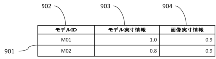
選択された判定モデル(以下、選択モデル)は、S802において取得した判定画像の画像実寸情報を関連付けて記憶しておく。図9は、S803において選択された選択モデルのデータベースの一部を例示する図である。図9に示す選択モデルのデータベース901は、記憶デバイス104又はネットワークインターフェース107を介してアクセス可能な外部記憶装置に格納されている。図9において、選択モデルのデータベース901は、選択モデルごとにモデルID902、モデル実寸情報903及び画像実寸情報904が記憶されている。モデルID902は、選択モデルの識別情報である。モデル実寸情報903は、学習に用いた変状画像の実寸情報であり、画像実寸情報904は、S802において取得した判定画像の画像実寸情報であり、本実施形態では画像実寸比である。
The selected determination model (hereinafter referred to as the selected model) is stored in association with the actual image size information of the determination image acquired in S802. FIG. 9 is a diagram exemplifying part of the selection model database selected in S803. A
S804では、判定部203が、S803において選択したそれぞれの選択モデルを用いて変状の属性を判定する。変状の属性の判定方法は、図3のS304と同様である。図10(a)は、S804において判定の結果として出力される変状の属性のデータベースの一部を例示する図である。図10(a)に示す変状の属性のデータベース1001は、記憶デバイス104又はネットワークインターフェース107を介してアクセス可能な外部記憶装置に格納されている。図10(a)において、変状の属性のデータベース1001は、判定された変状ごとに変状ID1002、モデルID1003、始点座標1004、終点座標1005及び変状の属性1006が記憶されている。変状ID1002は、判定された変状の識別情報である。モデルID1003は、変状の属性の判定に用いた選択モデルの識別情報である。始点座標1004は、判定された変状位置の始点座標である。終点座標1005は、判定された変状位置の終点座標である。変状の属性1006は、判定された変状の属性であり、本実施形態では変状幅である。図10(a)において、変状1007と変状1008は同じ位置の変状に対して異なる判定モデルを用いて変状の属性が判定されているので、同じ変状ID1002と異なるモデルID1003が登録されている。
In S804, the
S805では、補正部204が、S804において判定した変状の属性を補正する。補正部204は、図10(a)に示すデータベース1001の変状IDごとのモデルID1003について、図9に示す選択モデルのデータベース901を参照して、変状の属性の判定に用いた選択モデルのモデル実寸情報と画像実寸情報を取得する。また、補正部204は、実施形態1で説明した式2を用いて補正係数αを算出し、実施形態1で説明した式3を用いて変状の属性Cnを補正する。
In S805, the
以上の補正を、S804で判定され、図10(a)に示すデータベース1001に登録された変状の属性ごとに行う。補正後の変状の属性は、図10(b)に示す補正された変状の属性のデータベース1009に登録される。図10(b)は、S805において補正された変状の属性のデータベースの一部を例示する図である。図10(b)に示す補正後の変状の属性のデータベース1009は、記憶デバイス104又はネットワークインターフェース107を介してアクセス可能な外部記憶装置に格納されている。図10(b)において、補正後の変状の属性のデータベース1009は、補正された変状ごとに変状ID1002、モデルID1003、始点座標1004、終点座標1005、変状の属性1006及び補正後の変状の属性1010が記憶されている。変状ID1002は、補正された変状の識別情報である。モデルID1003は、変状の属性の判定に用いた選択モデルの識別情報である。始点座標1004は、補正された変状位置の始点座標である。終点座標1005は、補正された変状位置の終点座標である。変状の属性1006は、補正された変状の属性である。補正後の変状の属性1010は、補正された変状の属性であり、本実施形態では変状幅である。
The above correction is performed for each deformation attribute determined in S804 and registered in the
S806では、統合部701が、S805において補正した、複数の選択モデルを用いて判定した補正後の複数の変状の属性を統合する。統合部701は、例えば、異なる選択モデルを用いて判定された補正後の複数の変状の属性を、ユーザが指定した補正後の変状の属性に統合する。図11は、複数の選択モデルを用いて判定した補正後の複数の変状の属性を統合する方法を説明する図である。図11(a)に示す統合画面1101には、S801において取得した判定画像に、図10(b)のデータベース1009に登録されている各変状と、各変状について異なる選択モデルで判定された補正後の変状の属性が表示される。図11(a)は、統合画面1101に、例えば、図9のデータベース901に登録されているモデル実寸情報0.8mm/pixelの選択モデルを用いて判定された補正後の複数の変状の属性を含む判定画像1102と、モデル実寸情報1.0mm/pixelの選択モデルを用いて判定された補正後の複数の変状の属性を含む判定画像1103と、を表示する。そして、例えば、図11(a)の統合画面1101の判定画像1102において、ユーザが入力デバイス105を操作することにより変状1104を選択し、確定ボタン1105を操作すると、判定画像1102の複数の変状の属性が変状1104の属性に統合される。以上の処理を繰り返すことにより、図10(b)の変状IDごとに変状の属性が統合されたデータベースが生成される。なお、統合後のデータベースに統合前の属性を付記してもよい。
In S806, the
また、S802において取得した画像実寸情報が縦方向と横方向の画像実寸情報を含む場合、図11(b)に示す統合画面1106のように、図9のデータベース901において、縦方向の画像実寸情報から選択されたモデル実寸情報0.8mm/pixelの選択モデルを用いて判定された補正後の複数の変状の属性を含む判定画像1107と、横方向の画像実寸情報から選択されたモデル実寸情報1.0mm/pixelの選択モデルを用いて判定された補正後の複数の変状の属性を含む判定画像1108と、を表示する。そして、そして、例えば、図11(b)の統合画面1106のように判定画像1107及び/又は1108において、ユーザが入力デバイス105を操作することにより縦方向又は横方向の変状を選択し、確定ボタン1105を操作すると、判定画像1107及び/又は1108の複数の変状の属性が統合される。この場合、図10(b)のデータベース1009に登録されている始点座標1004と終点座標1005から変状の方向を判定し、画像実寸情報の方向が一致する変状を予め選択状態1109で表示してもよい。このようにすることで、ユーザが変状を選択する操作を行わずに、選択状態1109の変状を統合することができる。
When the actual image size information acquired in S802 includes vertical and horizontal image size information, vertical image size information is stored in the
以上のように、実施形態2によれば、変状の属性の判定精度と、判定画像の画像実寸情報の範囲をより向上することができる。これにより、変状の属性を判定する処理の信頼性が向上し、点検作業を効率化することが可能となる。 As described above, according to the second embodiment, it is possible to further improve the determination accuracy of the deformation attribute and the range of the image actual size information of the determination image. This improves the reliability of the process of determining the attribute of deformation, and makes it possible to improve the efficiency of inspection work.
なお、S803またはS805は省略してもよい。例えば、S803における選択モデルの選択を省略し、全ての判定モデルを用いてもよい。また、S805における変状の属性の補正を省略してもよい。 Note that S803 or S805 may be omitted. For example, the selection of the selection model in S803 may be omitted and all determination models may be used. Also, the correction of the deformation attribute in S805 may be omitted.
また、画像実寸情報を複数取得した場合や画像実寸情報が縦方向と横方向の画像実寸情報を含む場合は、それぞれの画像実寸情報について、S803からS306の処理を行えばよい。 Also, when a plurality of pieces of actual image size information are acquired or when the actual image size information includes vertical and horizontal image actual size information, the processing from S803 to S306 may be performed for each piece of image actual size information.
[他の実施形態]
本発明は、各実施形態の1以上の機能を実現するプログラムを、ネットワークや記憶媒体を介してシステムや装置に供給し、そのシステム又は装置のコンピュータの1つ以上のプロセッサがプログラムを読み出して実行する処理でも実現可能である。また、本発明は、1以上の機能を実現する回路(例えば、ASIC)によっても実現可能である。
[Other embodiments]
The present invention supplies a program that implements one or more functions of each embodiment to a system or device via a network or a storage medium, and one or more processors of the computer of the system or device reads and executes the program. It can also be realized by processing to The invention can also be implemented by a circuit (eg, an ASIC) that implements one or more functions.
発明は上記実施形態に制限されるものではなく、発明の精神及び範囲から離脱することなく、様々な変更及び変形が可能である。従って、発明の範囲を公にするために請求項を添付する。 The invention is not limited to the embodiments described above, and various modifications and variations are possible without departing from the spirit and scope of the invention. Accordingly, the claims are appended to make public the scope of the invention.
100、200、700…画像処理装置、101…制御部、102…不揮発性メモリ、104…記憶デバイス、201…取得部、202…選択部、203…判定部、204…補正部、701…統合部
DESCRIPTION OF
Claims (20)
前記第1の実寸情報と、予め学習を行い生成されたモデルとを用いて前記画像に含まれる変状の属性を判定する判定手段と、を有することを特徴とする画像処理装置。 obtaining means for obtaining first actual size information of an image including a deformation;
An image processing apparatus, comprising: determination means for determining an attribute of a deformation included in the image using the first actual size information and a model generated by learning in advance.
前記第1の実寸情報と前記第2の実寸情報とに基づいて、前記予め学習を行い生成されたモデルから前記判定を行うためのモデルを選択する選択手段と、をさらに有することを特徴とする請求項1に記載の画像処理装置。 storage means for storing a database that associates the model generated by learning in advance with second actual size information used for learning the model;
selection means for selecting a model for performing the determination from the models generated by learning in advance based on the first actual size information and the second actual size information. The image processing apparatus according to claim 1.
前記複数のモデルを用いて判定された変状の属性を統合する統合手段をさらに有することを特徴とする請求項2に記載の画像処理装置。 The selection means selects a plurality of models based on a difference between the first actual size information and the second actual size information;
3. The image processing apparatus according to claim 2, further comprising integrating means for integrating the deformation attributes determined using the plurality of models.
前記補正手段は、前記画像の縦方向及び横方向の実寸情報と前記第2の実寸情報との比に基づいて前記変状の属性を補正することを特徴とする請求項4又は5に記載の画像処理装置。 the first actual size information includes vertical and horizontal actual size information of the image;
6. A method according to claim 4, wherein said correcting means corrects said deformity attribute based on a ratio between said second actual size information and said vertical and horizontal size information of said image. Image processing device.
前記補正手段は、前記画像の縦方向及び横方向の実寸情報の平均と前記第2の実寸情報との比に基づいて前記変状の属性を補正することを特徴とする請求項4又は5に記載の画像処理装置。 the first actual size information includes vertical and horizontal actual size information of the image;
6. The apparatus according to claim 4, wherein said correction means corrects the attribute of said deformation based on a ratio between the average of the vertical and horizontal actual size information of said image and said second actual size information. The described image processing device.
前記統合手段は、前記画像の縦方向及び横方向の実寸情報と前記変状の方向とに基づいて前記変状の属性を統合することを特徴とする請求項8に記載の画像処理装置。 the first actual size information includes vertical and horizontal actual size information of the image;
9. The image processing apparatus according to claim 8, wherein said integrating means integrates attributes of said deformation based on information on actual vertical and horizontal dimensions of said image and the direction of said deformation.
取得手段が、変状を含む画像の第1の実寸情報を取得するステップと、
判定手段が、前記第1の実寸情報と、予め学習を行い生成されたモデルとを用いて前記画像に含まれる変状の属性を判定するステップと、を有することを特徴とする画像処理方法。 An image processing method comprising:
obtaining means for obtaining first actual size information of the image including the deformity;
An image processing method, wherein a determination means determines an attribute of a deformation included in the image using the first actual size information and a model generated by learning in advance.
Priority Applications (2)
| Application Number | Priority Date | Filing Date | Title |
|---|---|---|---|
| JP2021173413A JP2023063112A (en) | 2021-10-22 | 2021-10-22 | Image processing apparatus, image processing method, and program |
| US17/966,123 US20230130917A1 (en) | 2021-10-22 | 2022-10-14 | Image processing apparatus and image processing method |
Applications Claiming Priority (1)
| Application Number | Priority Date | Filing Date | Title |
|---|---|---|---|
| JP2021173413A JP2023063112A (en) | 2021-10-22 | 2021-10-22 | Image processing apparatus, image processing method, and program |
Publications (1)
| Publication Number | Publication Date |
|---|---|
| JP2023063112A true JP2023063112A (en) | 2023-05-09 |
Family
ID=86055764
Family Applications (1)
| Application Number | Title | Priority Date | Filing Date |
|---|---|---|---|
| JP2021173413A Pending JP2023063112A (en) | 2021-10-22 | 2021-10-22 | Image processing apparatus, image processing method, and program |
Country Status (2)
| Country | Link |
|---|---|
| US (1) | US20230130917A1 (en) |
| JP (1) | JP2023063112A (en) |
-
2021
- 2021-10-22 JP JP2021173413A patent/JP2023063112A/en active Pending
-
2022
- 2022-10-14 US US17/966,123 patent/US20230130917A1/en active Pending
Also Published As
| Publication number | Publication date |
|---|---|
| US20230130917A1 (en) | 2023-04-27 |
Similar Documents
| Publication | Publication Date | Title |
|---|---|---|
| JP6422573B2 (en) | Image processing apparatus, image processing method and program | |
| JP2007047930A (en) | Image processor and inspection device | |
| JP2021047197A (en) | Damage data editing device, damage data editing method and program | |
| JP2021196705A (en) | Image processing system, image processing method and program | |
| JP2006110190A (en) | Medical image data analyzing apparatus and method thereof | |
| JP7194410B2 (en) | Diagnostic method, program, and diagnostic device | |
| JP4686624B2 (en) | Information processing apparatus, image processing method, and program | |
| JP6786015B1 (en) | Motion analysis system and motion analysis program | |
| JP7136737B2 (en) | Three-dimensional position measuring device, three-dimensional position measuring method and program | |
| WO2023068323A1 (en) | Image processing device, image processing method, and program | |
| JP2023063112A (en) | Image processing apparatus, image processing method, and program | |
| JP4041060B2 (en) | Image processing apparatus and image processing method | |
| US11922659B2 (en) | Coordinate calculation apparatus, coordinate calculation method, and computer-readable recording medium | |
| JP2020024286A (en) | Measurement device, method for operating measurement device, and program | |
| JP2019174982A (en) | Model display control method and model display control program and model display control system | |
| JP2010278931A (en) | Image processing apparatus | |
| US7961931B2 (en) | Positioning measurement apparatus and method | |
| JP7329951B2 (en) | Image processing device and its control method | |
| JP6290743B2 (en) | Information processing apparatus and program | |
| JP2005062041A (en) | Soundness evaluation method, evaluation program and evaluation device | |
| KR20200002590A (en) | Inspection result presenting apparatus, inspection result presenting method and inspection result presenting program | |
| JP5411738B2 (en) | Hardness tester and program | |
| JP6399808B2 (en) | Image processing apparatus, image processing method, and program | |
| US20200034650A1 (en) | Measurement apparatus, measurement method, and computer-readable recording medium storing measurement program | |
| JP2020159969A (en) | Auxiliary facility state evaluation device, auxiliary facility state evaluation method, and auxiliary facility state evaluation program |