JP2022547255A - toilet seat assembly - Google Patents
toilet seat assembly Download PDFInfo
- Publication number
- JP2022547255A JP2022547255A JP2022502581A JP2022502581A JP2022547255A JP 2022547255 A JP2022547255 A JP 2022547255A JP 2022502581 A JP2022502581 A JP 2022502581A JP 2022502581 A JP2022502581 A JP 2022502581A JP 2022547255 A JP2022547255 A JP 2022547255A
- Authority
- JP
- Japan
- Prior art keywords
- toilet seat
- seat assembly
- liquid
- reservoir
- spray wand
- Prior art date
- Legal status (The legal status is an assumption and is not a legal conclusion. Google has not performed a legal analysis and makes no representation as to the accuracy of the status listed.)
- Pending
Links
- 239000007921 spray Substances 0.000 claims abstract description 263
- 238000004140 cleaning Methods 0.000 claims abstract description 94
- 238000001035 drying Methods 0.000 claims abstract description 41
- 239000012263 liquid product Substances 0.000 claims abstract description 25
- XLYOFNOQVPJJNP-UHFFFAOYSA-N water Substances O XLYOFNOQVPJJNP-UHFFFAOYSA-N 0.000 claims description 190
- 239000007788 liquid Substances 0.000 claims description 79
- 230000002070 germicidal effect Effects 0.000 claims description 50
- 238000010438 heat treatment Methods 0.000 claims description 28
- 238000000034 method Methods 0.000 claims description 25
- 238000004891 communication Methods 0.000 claims description 13
- 238000005507 spraying Methods 0.000 claims description 12
- 239000012530 fluid Substances 0.000 claims description 11
- 239000000523 sample Substances 0.000 claims description 7
- 238000007654 immersion Methods 0.000 claims description 5
- 230000004044 response Effects 0.000 claims description 5
- RYGMFSIKBFXOCR-UHFFFAOYSA-N Copper Chemical compound [Cu] RYGMFSIKBFXOCR-UHFFFAOYSA-N 0.000 claims description 3
- 229910052802 copper Inorganic materials 0.000 claims description 3
- 239000010949 copper Substances 0.000 claims description 3
- 230000000249 desinfective effect Effects 0.000 claims description 3
- 230000003134 recirculating effect Effects 0.000 claims description 3
- 238000005086 pumping Methods 0.000 claims description 2
- 230000001105 regulatory effect Effects 0.000 claims description 2
- 230000001960 triggered effect Effects 0.000 claims description 2
- 238000001514 detection method Methods 0.000 claims 1
- 230000002093 peripheral effect Effects 0.000 claims 1
- 229920000915 polyvinyl chloride Polymers 0.000 claims 1
- 239000004800 polyvinyl chloride Substances 0.000 claims 1
- 210000002640 perineum Anatomy 0.000 abstract description 48
- 238000005406 washing Methods 0.000 abstract description 10
- 239000012459 cleaning agent Substances 0.000 description 21
- 238000013459 approach Methods 0.000 description 10
- 238000012423 maintenance Methods 0.000 description 10
- 238000010586 diagram Methods 0.000 description 8
- 230000001954 sterilising effect Effects 0.000 description 8
- 230000009471 action Effects 0.000 description 7
- 239000004033 plastic Substances 0.000 description 7
- 229920003023 plastic Polymers 0.000 description 7
- 210000003484 anatomy Anatomy 0.000 description 5
- 230000000712 assembly Effects 0.000 description 5
- 238000000429 assembly Methods 0.000 description 5
- 210000001124 body fluid Anatomy 0.000 description 5
- 239000003599 detergent Substances 0.000 description 5
- 230000001276 controlling effect Effects 0.000 description 4
- 239000002274 desiccant Substances 0.000 description 4
- 238000005286 illumination Methods 0.000 description 4
- 230000000670 limiting effect Effects 0.000 description 4
- 239000000463 material Substances 0.000 description 4
- 238000004659 sterilization and disinfection Methods 0.000 description 4
- 230000004888 barrier function Effects 0.000 description 3
- 230000008878 coupling Effects 0.000 description 3
- 238000010168 coupling process Methods 0.000 description 3
- 238000005859 coupling reaction Methods 0.000 description 3
- 230000036961 partial effect Effects 0.000 description 3
- -1 polybutylene terephthalate Polymers 0.000 description 3
- 239000011347 resin Substances 0.000 description 3
- 229920005989 resin Polymers 0.000 description 3
- 125000006850 spacer group Chemical group 0.000 description 3
- 239000004909 Moisturizer Substances 0.000 description 2
- XLOMVQKBTHCTTD-UHFFFAOYSA-N Zinc monoxide Chemical compound [Zn]=O XLOMVQKBTHCTTD-UHFFFAOYSA-N 0.000 description 2
- 239000003795 chemical substances by application Substances 0.000 description 2
- 230000006735 deficit Effects 0.000 description 2
- 238000009826 distribution Methods 0.000 description 2
- 239000003814 drug Substances 0.000 description 2
- 238000011010 flushing procedure Methods 0.000 description 2
- 230000006870 function Effects 0.000 description 2
- 238000003780 insertion Methods 0.000 description 2
- 230000037431 insertion Effects 0.000 description 2
- 238000009434 installation Methods 0.000 description 2
- 230000002262 irrigation Effects 0.000 description 2
- 238000003973 irrigation Methods 0.000 description 2
- 239000000203 mixture Substances 0.000 description 2
- 238000010295 mobile communication Methods 0.000 description 2
- 230000001333 moisturizer Effects 0.000 description 2
- 229920001707 polybutylene terephthalate Polymers 0.000 description 2
- 229920000515 polycarbonate Polymers 0.000 description 2
- 239000004417 polycarbonate Substances 0.000 description 2
- 239000000047 product Substances 0.000 description 2
- 239000008400 supply water Substances 0.000 description 2
- 235000014692 zinc oxide Nutrition 0.000 description 2
- 239000011787 zinc oxide Substances 0.000 description 2
- 235000002961 Aloe barbadensis Nutrition 0.000 description 1
- 244000186892 Aloe vera Species 0.000 description 1
- 208000024827 Alzheimer disease Diseases 0.000 description 1
- 206010012289 Dementia Diseases 0.000 description 1
- LYCAIKOWRPUZTN-UHFFFAOYSA-N Ethylene glycol Chemical compound OCCO LYCAIKOWRPUZTN-UHFFFAOYSA-N 0.000 description 1
- AEMRFAOFKBGASW-UHFFFAOYSA-N Glycolic acid Natural products OCC(O)=O AEMRFAOFKBGASW-UHFFFAOYSA-N 0.000 description 1
- 230000001154 acute effect Effects 0.000 description 1
- 235000011399 aloe vera Nutrition 0.000 description 1
- 230000001580 bacterial effect Effects 0.000 description 1
- 244000052616 bacterial pathogen Species 0.000 description 1
- 238000005452 bending Methods 0.000 description 1
- 230000009286 beneficial effect Effects 0.000 description 1
- 238000007664 blowing Methods 0.000 description 1
- 229940105847 calamine Drugs 0.000 description 1
- 229910010293 ceramic material Inorganic materials 0.000 description 1
- KRKNYBCHXYNGOX-UHFFFAOYSA-N citric acid Chemical class OC(=O)CC(O)(C(O)=O)CC(O)=O KRKNYBCHXYNGOX-UHFFFAOYSA-N 0.000 description 1
- 239000011538 cleaning material Substances 0.000 description 1
- MRUAUOIMASANKQ-UHFFFAOYSA-N cocamidopropyl betaine Chemical compound CCCCCCCCCCCC(=O)NCCC[N+](C)(C)CC([O-])=O MRUAUOIMASANKQ-UHFFFAOYSA-N 0.000 description 1
- 229940073507 cocamidopropyl betaine Drugs 0.000 description 1
- 239000004020 conductor Substances 0.000 description 1
- 239000000356 contaminant Substances 0.000 description 1
- 239000006071 cream Substances 0.000 description 1
- 239000002781 deodorant agent Substances 0.000 description 1
- 230000000881 depressing effect Effects 0.000 description 1
- SOROIESOUPGGFO-UHFFFAOYSA-N diazolidinylurea Chemical compound OCNC(=O)N(CO)C1N(CO)C(=O)N(CO)C1=O SOROIESOUPGGFO-UHFFFAOYSA-N 0.000 description 1
- 229960001083 diazolidinylurea Drugs 0.000 description 1
- MOTZDAYCYVMXPC-UHFFFAOYSA-N dodecyl hydrogen sulfate Chemical compound CCCCCCCCCCCCOS(O)(=O)=O MOTZDAYCYVMXPC-UHFFFAOYSA-N 0.000 description 1
- 229940043264 dodecyl sulfate Drugs 0.000 description 1
- 229940079593 drug Drugs 0.000 description 1
- 238000010981 drying operation Methods 0.000 description 1
- 210000003608 fece Anatomy 0.000 description 1
- 239000006260 foam Substances 0.000 description 1
- 239000003205 fragrance Substances 0.000 description 1
- 239000011521 glass Substances 0.000 description 1
- 230000017525 heat dissipation Effects 0.000 description 1
- 229910052864 hemimorphite Inorganic materials 0.000 description 1
- 230000001771 impaired effect Effects 0.000 description 1
- 239000004615 ingredient Substances 0.000 description 1
- 238000009413 insulation Methods 0.000 description 1
- 230000002452 interceptive effect Effects 0.000 description 1
- 238000002483 medication Methods 0.000 description 1
- 238000012986 modification Methods 0.000 description 1
- 230000004048 modification Effects 0.000 description 1
- 230000004770 neurodegeneration Effects 0.000 description 1
- 208000015122 neurodegenerative disease Diseases 0.000 description 1
- 239000002674 ointment Substances 0.000 description 1
- 238000011022 operating instruction Methods 0.000 description 1
- 238000013021 overheating Methods 0.000 description 1
- 230000000737 periodic effect Effects 0.000 description 1
- 238000009428 plumbing Methods 0.000 description 1
- 230000002829 reductive effect Effects 0.000 description 1
- 238000003303 reheating Methods 0.000 description 1
- 230000003014 reinforcing effect Effects 0.000 description 1
- 239000000565 sealant Substances 0.000 description 1
- 229910001220 stainless steel Inorganic materials 0.000 description 1
- 239000010935 stainless steel Substances 0.000 description 1
- 230000003068 static effect Effects 0.000 description 1
- 238000003860 storage Methods 0.000 description 1
- 210000002700 urine Anatomy 0.000 description 1
- 239000011782 vitamin Substances 0.000 description 1
- 229940088594 vitamin Drugs 0.000 description 1
- 229930003231 vitamin Natural products 0.000 description 1
- 235000013343 vitamin Nutrition 0.000 description 1
- 238000005303 weighing Methods 0.000 description 1
- 238000004804 winding Methods 0.000 description 1
- CPYIZQLXMGRKSW-UHFFFAOYSA-N zinc;iron(3+);oxygen(2-) Chemical compound [O-2].[O-2].[O-2].[O-2].[Fe+3].[Fe+3].[Zn+2] CPYIZQLXMGRKSW-UHFFFAOYSA-N 0.000 description 1
Images


Classifications
-
- E—FIXED CONSTRUCTIONS
- E03—WATER SUPPLY; SEWERAGE
- E03D—WATER-CLOSETS OR URINALS WITH FLUSHING DEVICES; FLUSHING VALVES THEREFOR
- E03D9/00—Sanitary or other accessories for lavatories ; Devices for cleaning or disinfecting the toilet room or the toilet bowl; Devices for eliminating smells
- E03D9/08—Devices in the bowl producing upwardly-directed sprays; Modifications of the bowl for use with such devices ; Bidets; Combinations of bowls with urinals or bidets; Hot-air or other devices mounted in or on the bowl, urinal or bidet for cleaning or disinfecting
- E03D9/085—Hand-held spray heads for bidet use or for cleaning the bowl
-
- G—PHYSICS
- G05—CONTROLLING; REGULATING
- G05D—SYSTEMS FOR CONTROLLING OR REGULATING NON-ELECTRIC VARIABLES
- G05D23/00—Control of temperature
- G05D23/19—Control of temperature characterised by the use of electric means
- G05D23/1917—Control of temperature characterised by the use of electric means using digital means
-
- G—PHYSICS
- G05—CONTROLLING; REGULATING
- G05D—SYSTEMS FOR CONTROLLING OR REGULATING NON-ELECTRIC VARIABLES
- G05D23/00—Control of temperature
- G05D23/19—Control of temperature characterised by the use of electric means
- G05D23/27—Control of temperature characterised by the use of electric means with sensing element responsive to radiation
-
- G—PHYSICS
- G05—CONTROLLING; REGULATING
- G05D—SYSTEMS FOR CONTROLLING OR REGULATING NON-ELECTRIC VARIABLES
- G05D9/00—Level control, e.g. controlling quantity of material stored in vessel
- G05D9/02—Level control, e.g. controlling quantity of material stored in vessel without auxiliary power
Abstract
ハウジングとシートリッドを有するシートベースを含み、さらに、洗浄装置、乾燥装置、およびハウジング内に配置されたスプレーキャニスター装置を含む便座アセンブリが提供される。ユーザインターフェースを有するコントローラは、便座アセンブリの制御ユニットと通信して、便座アセンブリの構成要素の動作を制御するように構成されている。このように構成されているので、ユーザーは、洗浄装置を介してユーザーの会陰部を洗浄し、乾燥装置を介してユーザーの会陰部を乾燥し、スプレーキャニスター装置を介してユーザーの会陰部に1つまたは複数の液体製品をスプレーするために便座アセンブリを動作させることができる。【選択図】図7A toilet seat assembly is provided including a seat base having a housing and a seat lid, and further including a washing device, a drying device, and a spray canister device disposed within the housing. A controller having a user interface is configured to communicate with the control unit of the toilet seat assembly to control operation of the components of the toilet seat assembly. So configured, the user can clean the user's perineum via the cleaning device, dry the user's perineum via the drying device, and spray the user's perineum via the spray canister device. The toilet seat assembly can be operated to spray one or more liquid products. [Selection drawing] Fig. 7
Description
本開示は、便座アセンブリに関し、より具体的には、ユーザの個人衛生を支援するための便座アセンブリに関する。 BACKGROUND OF THE DISCLOSURE The present disclosure relates to toilet seat assemblies and, more particularly, to toilet seat assemblies for assisting a user in personal hygiene.
水性トイレシステムを含むものなどの便座アセンブリは、使用者の会陰部を洗浄し、清掃するために知られている。そのようなアセンブリは、助けなしに効果的に自分自身をケアし、そうでなければ自分自身を洗浄又は清掃することができない可能性がある器用さ又は移動性障害を有する個人のための医療及び補助生活用途にも関心が持たれている。それらの個人を支援するために、便座アセンブリは、排尿または排便後にその領域を洗浄するために、水および/または他の液体製品を使用者の会陰部へ供給するためのスプレーノズルを含むことができる。その後、便座アセンブリの乾燥機を用いて、会陰部を乾燥させることができる。 Toilet seat assemblies, such as those that include aqueous toilet systems, are known for washing and cleaning a user's perineum. Such an assembly would be a medical and medical aid for individuals with dexterity or mobility impairments who may not be able to effectively care for themselves, wash or clean themselves otherwise without assistance. There is also interest in assisted living applications. To assist those individuals, the toilet seat assembly may include a spray nozzle for delivering water and/or other liquid products to the user's perineum to cleanse the area after urinating or defecating. can. The dryer of the toilet seat assembly can then be used to dry the perineum.
手先が不自由な高齢者にとっては、便座アセンブリの操作、整備、および清掃が困難で負担になることがある。さらに、これらの便座アセンブリは、初期の認知症の人には操作が困難な場合がある。アルツハイマー病、または神経変性疾患は、操作指示が複雑であるためである。具体的には、便座アセンブリに含まれるボタンの数が多すぎる場合、または手順が多すぎる場合、そのような人は、便座アセンブリの使用方法を忘れてしまう可能性がある。また、便座アセンブリに液体や溶液を補充するための複雑な指示がある場合、手先が不器用な人にとっては、洗浄剤やその他の医薬品の交換が困難になる可能性がある。 For seniors with limited dexterity, operating, servicing, and cleaning toilet seat assemblies can be difficult and burdensome. Additionally, these toilet seat assemblies can be difficult for people with early dementia to operate. This is because Alzheimer's disease, or neurodegenerative disease, has complex operating instructions. Specifically, if the toilet seat assembly contains too many buttons or too many steps, such a person may forget how to use the toilet seat assembly. Also, if the toilet seat assembly has complicated instructions for refilling liquids and solutions, it can be difficult for people with poor dexterity to replace cleansers and other medications.
また、従来のスプレーノズルは、使用者の会陰部をスプレーするために伸長し、その後は体液との接触を避けるために収縮するように設計されているが、それでも、時間の経過と共にスプレーノズルまたは便座アセンブリの他の部分から種々の汚染物を清掃する必要がある場合がある。しかしながら、上述したように、これは、手先があまり器用でない人にとっては、介護が困難である場合がある。 Also, while conventional spray nozzles are designed to expand to spray the user's perineum and then contract to avoid contact with bodily fluids, over time the spray nozzle or Various contaminants may need to be cleaned from other parts of the toilet seat assembly. However, as noted above, this can be difficult to care for for those with less manual dexterity.
使いやすさのために設計され、その操作を単純化するための構成要素を含む便座アセンブリを有することが有益であろう。さらに、便座アセンブリが、使用者による手動での清掃を必要とせずに、清掃動作後にその特定の部分を消毒することができれば望ましいであろう。 It would be beneficial to have a toilet seat assembly that is designed for ease of use and includes components to simplify its operation. Additionally, it would be desirable if the toilet seat assembly could disinfect certain portions thereof after the cleaning action without requiring manual cleaning by the user.
本開示に従って、シートベース及びシートリッドを含み、シートベース内に配置された洗浄装置、乾燥装置、及びスプレーキャニスタ装置をさらに含む便座アセンブリが提供される。ユーザインターフェースを有するコントローラは、以下にさらに詳細に説明するように、便座アセンブリの制御ユニットと通信して、便座アセンブリの構成要素の動作を制御するように構成されている。このように構成されているので、ユーザは、洗浄装置を介してユーザの会陰部を洗浄し、乾燥装置を介してユーザの会陰部を乾燥し、スプレーキャニスタ装置を介してユーザの会陰部に1つまたは複数の液体製品をスプレーするために便座アセンブリを動作させることができる。 In accordance with the present disclosure, a toilet seat assembly is provided that includes a seat base and a seat lid, and further includes a cleaning device, a drying device, and a spray canister device disposed within the seat base. A controller having a user interface is configured to communicate with the control unit of the toilet seat assembly to control the operation of the components of the toilet seat assembly, as described in further detail below. So configured, the user can clean the user's perineum via the cleaning device, dry the user's perineum via the drying device, and spray the user's perineum via the spray canister device. The toilet seat assembly can be operated to spray one or more liquid products.
上述したように、便座アセンブリは、洗浄器具を含む。洗浄器具は、シートベース内に配置され、クレンザーリザーバ及び水リザーバに流体的に結合されたスプレーワンドと、スプレーワンドの外面の周りに少なくとも部分的に延在するカラーシュラウドと、を含む。スプレーワンドは、本体部分と、1つ以上のノズルを有するヘッド部分とを有し、その1つ以上のノズルを通して水リザーバからの水及び/又はクレンザーリザーバからの液体を送達するように構成される。洗浄装置のカラーシュラウドは、殺菌光源がスプレーワンドに殺菌光を照射してその殺菌を促進するように、スプレーワンドに近接して配置された1つ又は複数の殺菌光源を含んでもよい。 As noted above, the toilet seat assembly includes a cleaning implement. The cleaning implement includes a spray wand disposed within the seat base and fluidly coupled to the cleanser reservoir and the water reservoir, and a collar shroud extending at least partially around an outer surface of the spray wand. The spray wand has a body portion and a head portion having one or more nozzles configured to deliver water from the water reservoir and/or liquid from the cleanser reservoir through the one or more nozzles. . The color shroud of the cleaning device may include one or more germicidal light sources positioned proximate to the spray wand such that the germicidal light sources illuminate the spray wand with germicidal light to facilitate sterilization thereof.
1つ又は複数のモータが洗浄器具に動作可能に結合されてもよく、1つ又は複数のモータの1つは、スプレーワンドを格納位置と拡張位置の間で移動させるように構成されてもよい。さらに、1つ以上のモータの1つは、スプレーワンドのヘッド部分を回転させて水及び/又は洗浄剤を会陰部に供給するように構成されてもよい。動作において、モータは、コントローラのユーザインターフェースがユーザ入力を受信することに応答して、スプレーワンドを伸長及び回転させるように構成されてもよい。 One or more motors may be operably coupled to the cleaning implement, and one of the one or more motors may be configured to move the spray wand between the retracted position and the extended position. . Additionally, one of the one or more motors may be configured to rotate the head portion of the spray wand to dispense water and/or irrigant to the perineum. In operation, the motor may be configured to extend and rotate the spray wand in response to the user interface of the controller receiving user input.
いくつかの形態では、カラーシュラウドは、そこを通って延び、スプレーワンドの外面へのアクセスを可能にする1つ又は複数の管状開口を含んでもよい。スプレーワンドの外面にアクセスすることを可能にする1つ以上の開口は、その外面をすすぎ、洗浄するために水がそこからスプレーワンドに供給され得るように、便座アセンブリの水リザーバに流体的に結合され得る。 In some forms, the collar shroud may include one or more tubular openings extending therethrough to allow access to the outer surface of the spray wand. The one or more openings that allow access to the exterior surface of the spray wand are fluidly connected to the water reservoir of the toilet seat assembly so that water can be supplied therefrom to the spray wand for rinsing and cleaning the exterior surface thereof. can be combined.
いくつかの実施形態では、便座アセンブリは、乾燥装置をさらに含む。乾燥装置は、一般に、ファンと、加熱装置と、ファンからユーザの会陰部へ空気を供給するための導管とを含む。ファンは、洗浄装置を介して会陰部が水及び/又は清浄剤で洗浄された後に、導管及びそこに配置された加熱ユニットを通して空気を送風するように構成されている。ファンによって送出される空気の速度または空気の温度は、便座アセンブリに関連するコントローラによって調節されるように構成されている。 In some embodiments, the toilet seat assembly further includes a drying device. Drying devices generally include a fan, a heating device, and a conduit for supplying air from the fan to the user's perineum. The fan is configured to blow air through the conduit and the heating unit located therein after the perineum has been washed with water and/or cleansing agent through the washing device. The air velocity or air temperature delivered by the fan is configured to be regulated by a controller associated with the toilet seat assembly.
いくつかの構成において、液体製品を含むキャニスタと、開口部を有するキャニスタハウジングと、シャーシ要素と、シャーシ要素に摺動可能に結合されるトレイとを含むスプレーキャニスタ装置も提供される。スプレーキャニスタ装置およびその動作は、実質的にU.S.App.に開示されている。第16/426,436号、2019年5月30日に出願され、その全体が参照により本明細書に組み込まれる。特に、スプレーキャニスタ装置は、スプレーキャニスタ装置を使用して、ユーザの会陰部に液体製品を塗布するように、便座アセンブリに配置されてもよい。便座アセンブリの制御ユニットによって制御されるモータは、便座アセンブリ内の格納位置と便座アセンブリの開口部から外側に延びる拡張位置との間でトレイを摺動可能に動かすようにトレイに動作可能に結合されてもよい。このように構成された場合、キャニスタハウジングとキャニスタはその中に配置されたトレイは、格納位置と伸長位置の間でトレイと共に移動し、液体製品をユーザの会陰部に噴霧することができる。いくつかの態様において、スプレーキャニスタ装置は、ユーザの会陰部が洗浄装置及び乾燥装置によってそれぞれ洗浄及び乾燥された後に、液体製品をスプレーするように構成されてもよい。 In some configurations, a spray canister apparatus is also provided that includes a canister containing a liquid product, a canister housing having an opening, a chassis element, and a tray slidably coupled to the chassis element. The spray canister device and its operation are substantially described in U.S. Pat. S. App. disclosed in No. 16/426,436, filed May 30, 2019, which is incorporated herein by reference in its entirety. In particular, a spray canister device may be positioned on the toilet seat assembly such that the spray canister device is used to apply liquid product to the user's perineum. A motor controlled by a control unit of the toilet seat assembly is operably coupled to the tray to slidably move the tray between a retracted position within the toilet seat assembly and an extended position extending outwardly from the opening of the toilet seat assembly. may When so configured, the canister housing and the tray with the canister disposed therein can move with the tray between the retracted and extended positions to spray the liquid product onto the user's perineum. In some aspects, the spray canister device may be configured to spray the liquid product after the user's perineum has been cleaned and dried by the cleaning device and the drying device, respectively.
便座アセンブリに関連するコントローラは、便座アセンブリに含まれる構成要素の動作を制御するように構成される。コントローラは、ユーザ入力を受信するためのユーザインターフェースと、プロセッサまたは制御回路と、通信回路と、メモリとを含む。いくつかの態様では、ユーザインターフェースでユーザ入力を受け取ると、コントローラのプロセッサは、ユーザ入力を受信するために前記便座アセンブリの構成要素の動作を引き起こすための制御信号を前記制御ユニットに通信する通信回路を備え例えば、制御ユニットは、洗浄装置のモータに、水および/または洗浄剤を使用者の会陰部へ送達するための伸長位置へスプレーワンドを移動させるように構成された制御信号を通信することができる。 A controller associated with the toilet seat assembly is configured to control operation of components included in the toilet seat assembly. The controller includes a user interface for receiving user input, a processor or control circuitry, communication circuitry, and memory. In some aspects, upon receiving user input at the user interface, the processor of the controller communicates control signals to the control unit to cause operation of components of the toilet seat assembly to receive user input. For example, the control unit communicates to a motor of the irrigation device a control signal configured to move the spray wand to an extended position for delivering water and/or irrigant to the perineum of the user. can be done.
さらに、ユーザは、例えば、水リザーバ内の水の温度、乾燥装置からの空気の速度および温度など、以下にさらに詳細に説明するように、コントローラのユーザインターフェースを介して便座アセンブリの様々な特徴を調整することができる。加えて、または代替的に、便座アセンブリは、便座アセンブリを操作するために制御ユニットに結合された補助ユーザインターフェースをさらに含んでもよい。いくつかの形態では、制御ユニットに結合された補助ユーザインターフェースは、ユーザが便利にアクセスできるようにシートベースのハウジングに配置された圧電ボタンの形態である。 In addition, the user can control various features of the toilet seat assembly via the controller's user interface, such as, for example, the temperature of the water in the water reservoir, the velocity and temperature of the air from the dryer, etc., as described in more detail below. can be adjusted. Additionally or alternatively, the toilet seat assembly may further include an auxiliary user interface coupled to the control unit for operating the toilet seat assembly. In some forms, the auxiliary user interface coupled to the control unit is in the form of piezoelectric buttons located on the housing of the seat base for convenient access by the user.
例示的な便座アセンブリは、便座アセンブリを既存の便器及び水槽構造に固定するためのブラケットアセンブリをさらに含んでもよい。例えば、既存の便器の座面及び蓋を取り外し、ブラケットアセンブリを介して便座アセンブリを既存の便器に貼り付けてもよい。ブラケットアセンブリは、便座アセンブリを既存の便器及び水槽に取り付けるためのベースプレートと、アームプレートと、一対のヒンジと、を含んでもよい。他の態様では、ブラケットアセンブリは、アームプレートとヒンジのみを含んでもよい。ベースプレート、アームプレート、およびヒンジはそれぞれ、便器アセンブリが複数の異なるサイズの便器および水槽構造に貼り付けられ得るように、既存の便器のサイズに応じて調整するための手段を含む。例えば、ベースプレート、アームプレート、およびヒンジは、選択された便器のサイズおよび高さに応じて整列するためのスロットを含んでもよい。いくつかの態様では、ベースプレートは、ユーザの便座アセンブリからの立ち上がり及び便座アセンブリへの着座を容易にするために、便器アセンブリに近接して配置される1つ又は複数のグラブバーに取り付けるように構成されたスリーブ部分を含んでもよい。 The exemplary toilet seat assembly may further include a bracket assembly for securing the toilet seat assembly to existing toilet and basin structures. For example, the seat and lid of an existing toilet bowl may be removed and the seat assembly attached to the existing toilet bowl via a bracket assembly. The bracket assembly may include a base plate, arm plates, and a pair of hinges for attaching the seat assembly to existing toilet bowls and tubs. In other aspects, the bracket assembly may include only arm plates and hinges. The base plate, arm plates and hinges each include means for adjusting according to existing toilet bowl sizes so that the toilet bowl assembly can be applied to a plurality of differently sized toilet bowl and tub structures. For example, the base plate, arm plates, and hinges may include slots for alignment according to the size and height of the toilet bowl selected. In some aspects, the baseplate is configured to attach to one or more grab bars positioned proximate the toilet assembly to facilitate a user's standing up from and seating on the toilet seat assembly. may include a sleeve portion.
ここで図、より具体的には図1を参照すると、ベース部分103とそれに結合されたハウジング104を有するシートベース102を含み、さらに複数の支持部107を有する蓋106を含む便座アセンブリ100が示されている。漏電遮断器(GFCI)コンセントなどの標準的な壁コンセントに接続するための壁コネクタ112を有する電源コード110が、便座アセンブリ100から延びており、便座アセンブリ100の構成要素に電力を供給するように構成されているのが示されている。上述したように、洗浄装置200、乾燥装置300、およびスプレーキャニスタ装置400(すべて図2に示す)が便座アセンブリ100のシートベース102に配置される。リモートコントロール152の形態のコントローラ150が、便座アセンブリ100に関連付けられ、ユーザインターフェース154を介してその動作を制御するように構成されているのが示されている。メンテナンスカバー114は、便座アセンブリ100の構成要素を整備するための1つ以上の開口部(図14に示す)を覆う閉位置にあるハウジング104の後部部分116に配置される。便座アセンブリ100の各構成要素については、以下で順次説明する。
Referring now to the figures, and more particularly to FIG. 1, there is shown a
シートベース102のハウジング104は、使用者の快適さのために形状及び輪郭が決められてもよい。例えば、ハウジング104は、移動障害のある個人が便座アセンブリ100に座ること、及び便座アセンブリ100から立ち上がることを容易にし、支援するために、斜めに傾斜していてもよい。より詳細には、座面ベース102は、その前方に向かって下方に角度を付けられてもよい。以下に説明するように、便座アセンブリ100のシートベース102には、様々な電気部品が配置されている。そこに配置された電気部品に干渉するような水や体液のシートベース102への浸入を抑制するために、シートベース102を構成するハウジング104およびベース部103は、ハウジング104がシートベース部103の端部に重なるように結合されてもよい。加えて又は代替的に、シートベース102を水又は体液から絶縁するために、ゴムガスケットのような、ハウジング104とベース部分103との間に配置されるシール(図示せず)が含まれてもよい。示されるように、ハンドル118は、便座アセンブリ100から立ち上がること、および便座アセンブリ100に座ることを容易にするために、ハウジング104の側面に位置決めされてもよい。
The
ベース部分103及びハウジング104を含むシートベース102は、洗浄を容易にするために、ポリカーボネート及びポリブチレンテレフタレート(PC-PBT)組成物で形成されてもよい。他の形態では、シートベース102は、急性期及び急性期後のケア設定の両方で典型的に使用される他のプラスチック又は樹脂で形成されてもよい。蓋106および便座アセンブリ100の他の構成要素、例えばメンテナンスカバー114も、清掃の容易さおよび消毒の容易さを促進するために、プラスチックまたは樹脂材料で形成されてもよい。例えば、蓋106および他の構成要素も、ポリカーボネートおよびポリブチレンテレフタレート(PC-PBT)組成物で形成されてもよい。
図示されているように、蓋106は、蓋106がシートベース102のハウジング104に近接した閉位置にあるときにリブ部材108が蓋106を支持するように、その内面120上に6つの補強リブ部材108の形態の支持体107を含んでいる。他の形態では、蓋106は、任意の数の強化リブ部材108を含んでもよい。いくつかの実施形態では、支持体107は、代替的に、蓋106を支持するように構成された他の構造のうち、支持柱、ウェッジ、及びリッジとして形成されてもよい。そのように構成されると、蓋106が閉位置にあるとき、ユーザは、蓋106がユーザの体重で壊れる、曲がる、または他の方法で座屈するリスクが低くなるように、強化された支持で蓋の上に座ることができる。いくつかの形態では、蓋106は、強化された剛性を促進するために、弾力性のある、耐久性のあるプラスチック又は樹脂材料で作られる。1つの例示的な実施形態では、便座アセンブリ100は、蓋が閉位置にあるとき、最大325ポンドのユーザを支持するように構成される。さらに、便座アセンブリ100は、いくつかの構成において、蓋が閉じた位置と蓋が開いた位置の両方において、最大325ポンドのユーザを支持するように構成されている。
As shown,
図2は、例えば洗浄装置200、乾燥装置300、及びスプレーキャニスタ装置400を含む便座アセンブリ100の内部構成要素を明らかにするためにシートベース102のハウジング104を取り外した、図1の便座アセンブリを示す図である。図示されているように、洗浄装置200は、水及び/又は洗浄剤を使用者の会陰部に送達するために、水リザーバ204及び洗浄剤リザーバ206に流体的に結合されているスプレーワンド202を含む。シートベース102に配置された構成要素の数のために、図示を容易にするために、洗浄器具200の構成要素間の流体接続(例えば、プラスチック又はゴムチューブ)は、図2に示されておらず、代わりに図3においてより詳細に見ることができる。
FIG. 2 shows the seat assembly of FIG. 1 with the
さらに、洗浄装置200は、スプレーワンド202の外面210の少なくとも一部の周りに延在するカラーシュラウド208を含んでもよい。好ましい形態では、カラーシュラウド208は、以下に更に詳細に論じるように、ユーザの会陰部が水及び/又は洗浄剤でスプレーされた後にスプレーワンド202を殺菌するための1つ又は複数の殺菌性光源(図7に示す)を含む。カラーシュラウド208は、洗浄操作後にスプレーワンド202をすすぐために水が開口部212、212’を通じて供給され得るように、スプレーワンド202の外面210へのアクセスを可能にするその側壁214を通る1又は複数の開口部(すなわち、図6に示す開口部212、212’)を含むことができる。
Additionally,
図示されているように、スプレーワンド202はモータ216に結合されており、モータ216は、スプレーワンド202を格納位置(すなわち、便座アセンブリ100のシートベース102内に配置される)と拡張位置(すなわち、便座アセンブリ100のシートベース102から延びる)との間で動かすように構成される。スプレーワンド202が伸長位置にあると、水及びクレンザーリザーバ204、206に結合された1つ以上のポンプ(水ポンプ218、又はクレンザーポンプ220など)が、水及び/又はクレンザーをスプレーワンド202に供給してそのノズル222から使用者の会陰部へ噴出させることができる。さらに、スプレーワンド202は、いくつかの構成において、スプレーワンド202を回転させるために、以下に説明するような補助モータに結合される。
As shown, the
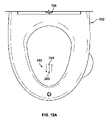
図2に見られる例示的な乾燥装置300は、ファン302、加熱ユニット304(図12に示す)、及び導管306を含む。導管306の一端は、乾燥カバー308によって覆われてもよい。ファン302は、導管306を通して、そこに配置された加熱ユニット304を通して空気を吹き込み、洗浄装置200を介して会陰部が水及び/又は清浄剤で洗浄された後に、ユーザの会陰部に空気を供給するように構成されている。ファン302によって送られる空気の速度又は空気の温度は、コントローラ150のユーザインターフェース154を介してユーザによって調整され得る。
The
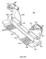
スプレーキャニスタ装置400は、液体製品を含むキャニスタ402と、開口部を有するキャニスタハウジング404と、シャーシ要素406と、シャーシ要素406に摺動可能に結合されたトレイ408と、を含む。図示された形態では、スプレーキャニスタ装置400は便座アセンブリ100に配置される。モータ410がトレイ408に動作可能に結合され、トレイ408をシートベース102内の格納位置とシートベース102の開口部から外側に延びる拡張位置との間でスライド可能に移動させる。このように構成されているので、キャニスタハウジング404及びその中に配置されたキャニスタ402は、液体製品を使用者の会陰部に噴霧し、その後、初期位置に引き戻されるように、トレイ408と共に格納位置と拡張位置との間で移動させることができる。いくつかの形態では、スプレーキャニスタ装置400は、ユーザの会陰部が洗浄装置200及び乾燥装置300によってそれぞれ洗浄及び乾燥された後に、液体製品をスプレーするように構成されてもよい。スプレーキャニスタ装置400は、便座アセンブリ100に関連するコントローラ150を介して操作されるように構成されている。
電源コード110から電力を受け、便座アセンブリ100の制御ユニット124に結合される電源122がシートベース102に配置されてもよい。制御ユニット124は、便座アセンブリ100の構成要素を制御するための1つまたは複数の回路基板126、128を含んでもよい。例えば、回路基板126は、電源回路を含む電源回路基板であってもよく、回路基板128は、制御回路を含む制御回路基板であってもよい。回路基板126,128は、例えば、当該技術分野で公知のプリント回路基板(PCB)として製造されてもよい。
A
制御ユニット124は、以下に更に詳細に説明するように、水及び/又はクレンザーを噴霧する洗浄装置200の動作を引き起こし、乾燥装置300の動作を引き起こし、スプレーキャニスタ装置400の動作を引き起こすように構成されてもよい。制御ユニット124は、プロセッサ130と、リモートコントロール152などの便座アセンブリ100に関連するコントローラ150からの通信を受信するための通信回路132(図16に示す)とを含んでもよい。そのように構成された、コントローラ150のユーザインターフェース154は、コントローラ150に制御信号を制御ユニット124に通信させて、便座アセンブリ100の構成要素の1つの動作または調節を引き起こすように構成されたユーザ入力を受信してもよい。
The
図1及び図2の両方に見られるように、便座アセンブリ100上に使用者が存在するかどうかを判断するために、シートベース102に近接してセンサ134が配置されてもよい。例えば、センサ134は、ユーザが存在するときにセンサ134が検出できるように、ガラスまたは薄いプラスチックなどの半透明材料で作られた窓136の背後に配置されてもよい。いくつかの形態では、センサ134は、便座アセンブリ100の制御ユニット124に結合された赤外線センサ、光電センサ、または超音波センサであってもよい。センサ134がユーザが存在することを検出しない場合、センサ134は、例えば、ユーザが存在しないときに水および/または洗浄剤が便座アセンブリ100から周囲に噴霧されないように、制御ユニット124が洗浄装置200を動作させることを抑制してもよい。あるいは、圧力センサ(図示せず)をシートベース102のハウジング104に組み込んで、使用者の存在を評価してもよい
As seen in both FIGS. 1 and 2, a
便座アセンブリ100は、例えば、便座アセンブリ100が洗浄及び/又は乾燥動作を完了すると音を発するように構成されたスピーカ(図示せず)をさらに含んでもよい。いくつかの形態では、スピーカーは、そこから音を発生させるために、コントローラ150に結合されるか、またはコントローラと一体化されてもよい。他の形態では、スピーカーは、シートベース102のハウジング104に近接して配置されてもよい。スピーカーの音量は、便座アセンブリ100に関連するコントローラ150を介して調整されてもよい。いくつかの実施形態では、スピーカーは、例えばBluetoothなどの無線短距離通信プロトコルを介してユーザのモバイル通信デバイス(例えば、携帯電話又はスマートフォン)と接続し、ユーザによって選択されたオーディオを再生するように構成されてもよい。
The
いくつかの形態では、便座アセンブリ100は、その一部を照明するためにシートベース102のハウジング104に近接して配置された光源(図示せず)を追加的に含んでもよい。例えば、光源は、コントローラ150を介してオン又はオフされてもよく、薄暗い場所で便座アセンブリ100を使用し、及び/又は清掃するために望ましい場合がある。
In some forms, the
さらに又は代替的に、コントローラ150及び/又は制御ユニット124と通信可能に結合された補助ユーザインターフェース138を含んでもよい。例えば、補助ユーザインターフェース138は、便利なアクセスのために、シートベース102のハウジング104の表面に近接して配置されてもよい。図1及び図2に示すように、補助ユーザインターフェース138は、圧電ボタン140の形態である。圧電ボタン140は、シートベース102の内部における水または体液の浸入を抑制するために機械的に密閉されてもよい(例えば、可撓性フィルムまたはプラスチックを用いて)。図示の形態では、補助ユーザインターフェース138は、便座アセンブリ100を使用する個人にとって便利なアクセス(例えば、ユーザの脚が配置されるであろう場所の間)のために、ハウジング104の前部分142に配置される。
Additionally or alternatively, an
いくつかの形態では、補助ユーザインターフェース138は、便座アセンブリ100の異なる機能を作動させるために複数回作動させることができる。例えば、1回のタッチで便座アセンブリ100がスプレーワンド202を動作させてユーザの会陰部を洗浄してもよく、2回の押下で洗浄と乾燥の両方の動作をさせてもよい。他の実施形態では、ユーザは、補助ユーザインターフェース138がユーザ入力を受信することに応答して、発生する操作の指定順序をプログラムすることができる。例えば、ユーザは、補助ユーザインターフェース138がユーザ入力を受信したときに、洗浄装置200及び乾燥装置300の動作のみが発生することを選択することができる。このように構成された場合、コントローラ150のユーザインターフェース154と補助ユーザインターフェース138の両方を使用して、便座アセンブリ100を操作することができる。さらに、補助ユーザインターフェース138は、ユーザに対して様々な動作条件を示すように構成された、LED144の形態などの1つまたは複数のインジケータを含んでもよい。例えば、インジケータがLED144である実施形態では、LED144の照明は、青色の光を介して洗浄動作の終了を示し得るか、またはLED144は、アンバー色の光を介して壊れた部品など、便座アセンブリ100のエラーを示し得る。他の形態では、ユーザに異なる情報を示すために、任意の色を選択することができる。
In some forms, the
いくつかの実施形態において、便座アセンブリ100は、ハウジング104の表面を加熱するためにシートベース102の内部に配置されたシートベースヒーター(図示せず)を含む。寒い気候に位置する一部の個人にとって、便座アセンブリ100を使用する前にシートベース102のハウジング104が加熱されることが望ましい場合がある。シートベースヒーターは、便座アセンブリ100に関連するコントローラ150によって制御されてもよく、さらに、コントローラ150のユーザインターフェース154で選択され得る、ユーザの好みに応じた低、中、および高などの様々な加熱設定を含んでもよい。
In some embodiments, the
洗浄装置200は、図3~図11に関してより詳細に説明される。今’-図3を参照すると、説明を簡単にするために、ハウジング104、乾燥装置300、およびスプレーキャニスタ装置400を含む便座アセンブリ100の様々な他の構成要素は、洗浄装置200およびそれに接続された構成要素をより明確に示すために取り除かれている。示されるように、洗浄装置200は、スプレーワンド202と、スプレーワンド202の外面210の周りに延びるカラーシュラウド208とを含む モーター216がスプレーワンド202に結合され、ユーザの会陰部に水および/または洗浄剤を供給するために、スプレーワンド202を格納位置と拡張位置との間で移動するように構成される。
図3に示すように、スプレーワンド202は、そのヘッド部分224が便座アセンブリ100のシートベース102から部分的に延びた状態で、格納位置(すなわち、シートベース102の内側)と拡張位置(すなわち、シートベース102の外側)の間で通過中である。そのように構成されているので、モータ216は、以下にさらに詳細に論じるように、スプレーワンド202を便座アセンブリ100のシートベース102の外に延出させ、使用者の会陰部に水および/または洗浄剤を送達させることができる。いくつかの形態では、スプレーワンド202は、格納位置と伸長位置との間の異なる所定点で停止するように構成されてもよい。例えば、ユーザの好みに応じて、スプレーワンド202は、シートベース102から約10mm~約50mm伸びるように構成されてもよい。他の形態では、スプレーワンド202は、便座アセンブリ100のシートベース102の外側にさらに延在してもよい。いくつかの形態では、スプレーワンド202は、その上での細菌又はバクテリアの成長を抑制するために、ステンレス鋼で作られてもよい。
As shown in FIG. 3, the
上述したように、便座アセンブリ100のコントローラ150は、洗浄装置200を動作させるように構成されてもよい。例えば、コントローラ150のユーザインターフェース154がユーザ入力を受信することに応答して、コントローラ150は、スプレーワンド202に結合されたモータ216に、スプレーワンド202を拡張位置へ移動させるように構成されてもよい。さらに、ユーザ入力は、後述するように、モータ216又は別の別個のモータのいずれかによるスプレーワンド202の回転を引き起こしてもよい。このように構成されたコントローラ150は、スプレーワンド202を格納位置と伸長位置との間で移動させ、スプレーワンド202を回転させて、水及び/又は洗浄剤を会陰部の正確な領域に供給してもよい。
As noted above,
以下でさらに詳細に説明するように、ユーザは、コントローラ150のユーザインターフェース154を介して、会陰部領域の所望の被覆に応じて、スプレーワンド202の選択されたスプレーパターンをプログラムすることもできる。さらに、ユーザは、コントローラ150のユーザインターフェース154を介して、水時間(例えば、スプレーワンド202が水及び/又は洗浄剤を噴霧する時間量)を選択することもできる。そのような特徴は、図16A及び16Bに関してさらに説明するように、コントローラ150のメモリにプログラムされ、記憶されてもよい。
As will be described in more detail below, the user can also program the selected spray pattern of the
水リザーバ204とクレンザーリザーバ206は、便座アセンブリ100のシートベース102に配置されているのが示されている。動作において、水リザーバ204は、ある量の水を含むように構成され、クレンザーリザーバ206は、ある量のクレンザー又は他の液体製品を含むように構成される。例えば、水リザーバ204は、約600~605立方センチメートルの水を収容するように構成されてもよく、クレンザーリザーバ206は、約300~350立方センチメートルのクレンザーを収容するように構成されてもよい。
A
水リザーバ204及びクレンザーリザーバ206の両方は、水及び/又はクレンザーのいずれかがスプレーワンド202のノズル222を介してユーザの会陰部に送達され得るように、チューブ、チャネル等を介してスプレーワンドに流体的に結合されてもよい。他の実施形態では、スプレーワンド202のヘッド部分224は、1つのノズルが水ホルンに流体的に結合され、水リザーバ204から水を送達するように構成され、他のノズルが洗浄剤リザーバ206に流体的に結合され、洗浄剤を送達するように構成された2つの別々のノズルを含んでいてもよい。さらに、水リザーバ204及びクレンザーリザーバ206の両方は、各リザーバ204、206から洗浄装置200のスプレーワンド202にそれぞれの液体を圧送するために、それぞれ水ポンプ218及びクレンザーポンプ220に動作可能に結合される。1つのアプローチによって、水リザーバ204及び水ポンプ218は、毎分約600mL~約800mLの間で吐出するように構成される。別の例示的な実施形態では、水リザーバ204及び水ポンプ218は、1分当たり約605mL~約750mLをディスペンスする。
Both
クレンザーリザーバに収容されるクレンザー又は他の液体製品は、例えば、他の成分のうち、水、アロエベラ、保湿剤、消臭剤、ビタミン、香料、コカミドプロピルベタイン、ラウリル硫酸、ジアゾリジニル尿素、メチルパラベンプロピレングリコール、及び/又はクエン酸付加物の量を含むことができる。 Cleansers or other liquid products contained in the cleanser reservoir may include, for example, water, aloe vera, moisturizers, deodorants, vitamins, fragrances, cocamidopropyl betaine, lauryl sulfate, diazolidinyl urea, methylparaben propylene, among other ingredients. Amounts of glycol and/or citric acid adducts may be included.
図示された実施形態では、水入口226が電源コード110に隣接して配置されて示されており、便座アセンブリ100が配置されている浴室の既存の配管など、外部の水源に結合されるように構成されている。いくつかの形態では、水入口226は、水入口226からの水が洗浄装置200の動作のために水リザーバ204を継続的に満たすように、水リザーバ204に直接結合されてもよい。他の形態では、水入口226は、便座アセンブリ100に配置された水調整器(図示せず)に結合されてもよく、この水調整器は、水が、あらゆる流体接続部を破裂させ、水リザーバ204を過充填し、または便座アセンブリ100の構成要素を他の方法で損傷し得る高すぎる圧力で水リザーバ204に流入しないように、水入口226を通って入る水の水圧を減少するよう構成される。
In the illustrated embodiment, the
さらに、図3に示すように、水リザーバ204はチューブ228を介して水ポンプ218に接続され、水リザーバ204はさらにチューブ230を介してスプレーワンドに接続されている。カラーシュラウド208が、そこを通してスプレーワンド202の外面210へのアクセスを可能にする開口部212、212’を含む実施形態では、水リザーバ204からの水が、スプレーワンド202をすすぐためにスプレーワンド202及びカラーシュラウド208の開口部212、212’の両方に供給できるように切替弁(図示せず)が含まれてもよい。そのように構成された場合、水リザーバ204内の水は、水入口226を介して受け取られ、チューブ232を介して水リザーバ204に流れ、その後、ポンプ218を介してチューブ230及び/又はチューブ234を介してカラーシュラウド208の開口212、212’にスプレーワンドに送出されてもよい。
Further, as shown in FIG. 3,
水リザーバ204は、水リザーバ204内の水の温度がユーザによって調節され得るように、ヒーター又は加熱部材をさらに含んでもよい。例えば、浸漬ヒーター231(図15に示す)は、水リザーバ204内に含まれる水を所望の温度まで加熱するために使用されてもよい。ユーザは、洗浄装置200で洗浄動作を行うために、より暖かい水又はより冷たい水を使用することを望むことができ、温度は、コントローラ150のユーザインターフェース154を介して調整されてもよい。例えば、ユーザインターフェース154は、低、中、及び高などの温度オプションをユーザに提供してもよい。他の形態では、ユーザインターフェース154は、水リザーバ204内の水の温度を正確に選択するためのスライド式スケール又はダイヤルを含んでもよい。水リザーバ204内の水がユーザに噴霧するために熱くなりすぎるのを防ぐために、サーミスタ236がヒーターを制御するように構成された回路に組み込まれてもよく、水の温度がサーミスタ236の抵抗値によって少なくとも部分的に決まる閾値よりも上昇すると洗浄装置200がスプレーワンド202を介して水を噴霧するのを阻害するために使用されてもよい。
同様にして、クレンザーリザーバ206は、チューブ238を介してクレンザーポンプ220に流体的に接続され、さらにチューブ240を介してスプレーワンド202に接続される。動作において、クレンザーリザーバ206内のクレンザーは、クレンザーポンプ220を介してスプレーワンド202に圧送され、そのノズル222を介して使用者の会陰部にクレンザーを送達することができる。あるいは、上述したように、清浄剤は、スプレーワンド202のヘッド部分224に配置された別個のノズルを介して送達されてもよい。
Similarly,
クレンザーリザーバ206は、追加のクレンザーを受け取るためにその上面244に配置されたバルブ242を含む。上述したように、メンテナンスカバー114(図1に示す)は、メンテナンスカバー114が閉位置にあるとき、補充用のバルブ242を覆っている。いくつかの形態では、弁242は、追加の清浄剤を含む充填ボトルが弁242を押し下げ、清浄剤リザーバを再充填するために対応する蓋を必要とするように、キー付き接続部を含んでもよい。例えば、バルブ242は、バルブ242をドーズ位置に継続的に偏らせるためのばね(図示せず)を含んでもよい。充填ボトルの蓋を介して弁242を押し下げると、そこに含まれる洗浄剤が洗浄剤リザーバ206に流入して、リザーバ206を洗浄剤又は他の液体製品で再充填することができる。そのように構成されたこの圧力作動構成は、高齢で器用でない使用者がクレンザーをこぼす可能性があることを抑制する。さらに、充填ボトルの蓋がバルブ242に嵌合結合されると、充填ボトルの操作は必要ない(例えば、充填ボトルから洗浄剤リザーバ206への洗浄剤の流れを引き起こすために充填ボトルを絞ったり操作したりする必要はない)。
The
さらに、水リザーバ204及びクレンザーリザーバ206の両方は、そこに含まれる液体のレベルが所定の閾値以下に低下したときに検出するためのレベルセンサ241(例えば、図15に示すフロートスイッチ243)を含んでもよい。各センサは、便座アセンブリ100に関連するインジケータに結合されて、その中の液体のレベルが低く、交換が必要なときに示すことができる。例えば、各センサは、圧電ボタン140のLED144またはコントローラ150上のLEDに結合されてもよく、センサがクレンザー/水のレベルが低いことを検出すると、コントローラ150上のLED144またはLEDが点灯してユーザにそのことを示すようにする。いくつかの形態では、1つの色が水リザーバ204内の液体が低いことを示し、別の色がクレンザーリザーバ206内の液体が低いことを示すように、各センサに対して異なる色のLEDが使用されてもよい。あるいは、センサは、コントローラ150のユーザインターフェース154に通信可能に結合され、例えば、その画面上でユーザに水及び/又はクレンザーのレベルが低いことを示してもよい。
Additionally, both the
いくつかの実施形態では、水リザーバ204は、ユーザ入力を必要とせずに、水入口226からの水を介して連続的に補充されてもよい。例えば、水リザーバ204の水位がある閾値以下であることをセンサが検出すると、便座アセンブリ100の制御ユニット124は、水入口226の弁(図示せず)を制御して、水リザーバ204にさらに水を流入させて水リザーバ204を再充填させてもよい。
In some embodiments,
図4A及び図4Bは、それぞれ格納位置及び拡張位置にあるスプレーワンド202を示す。以下に更に詳細に説明するように、1つ以上のモータは、スプレーワンド202を図4A及び4Bに示す位置の間で移動させて、ユーザの会陰部に水及び/又は洗浄剤を供給するように構成される。動作において、スプレーワンド202は、カラーシュラウド208を通って、シートベース102の外に進められる。
Figures 4A and 4B show the
上述したように、洗浄装置200は、モータ216のような1つまたは複数のモータを含む。図示のように、モータ216は、スプレーワンドを格納位置(図4Aに見られる)と伸長位置(図4Bに見られる)との間で移動させるように構成される。モータ216は、モータマウント246を介して便座アセンブリ100に搭載されてもよい。いくつかの態様において、モータ216は、ステッピングモータであってもよい。図示されているように、モータ216は、スプレーワンド202に連結されたスライドプレート248を方向Aに前進させるように構成されており、その結果、それに連結されたスプレーワンド202は、便座アセンブリ100のシートベース102から伸長位置に向かって方向Aに前進させられる。さらに、1つの例示的なアプローチでは、スライドプレート248がガイド250に沿って軌道上をスライドして、スプレーワンド202が動作中に望ましくない方向に動くことを抑制するように、細長いロッド252の形態のようなガイド250が提供されてもよい。
As mentioned above,
洗浄装置200は、それに接続されたアクチュエータ247を有する図4Bに示すような力センサ245をさらに含んでもよい。スプレーワンド202が格納位置に戻ると、スライドプレート248は、アクチュエータ247に接触して押し下げ、スプレーワンド202が完全に格納されたことを示してもよい。アクチュエータ247の押下時に、いくつかの形態では、力センサ245は、スプレーワンド202のすすぎと、以下に説明するようにカラーシュラウド208の殺菌光源276の照明とをトリガーしてもよい。
The
上述したスライドプレート248は、いくつかの実施形態において、図4Bに示すモータ256などの第2のモータを介してスプレーワンド202を回転させるように構成された回転アダプタ254に追加的に結合されてもよい。このような構成では、回転アダプタ254は、スペーサ260、260’を介してフランジ258に結合され、フランジ258は、その端部264でスプレーワンド202の本体部分262に順に結合される。スペーサ260、260’は、典型的には、回転アダプタ254とフランジ258との間に間隔を設け、スプレーワンド202と水及び洗浄剤リザーバ204、206との間の流体接続を収容するために使用される。例えば、図3に示すように、水リザーバ204からのチューブ230及び清浄剤リザーバ206からのチューブ240は、スペーサ260、260’によって生じるフランジ258と回転アダプタ254との間の空間において、水及び清浄剤をそれぞれスプレーワンド202に供給する。
The
回転アダプタ254は、例えば図4Bに示すモータ256によって回転するように構成される。 あるいは、単一のモータが、スプレーワンド202を格納位置と拡張位置との間で動かすこととスプレーワンド202を回転させることの両方に対応できるように複数のギアリングで構成されてもよい。本明細書でさらに詳細に説明するように、便座アセンブリ100に関連するコントローラ150は、1つ以上のモータの動作を引き起こして、洗浄装置200のスプレーワンド202を移動及び回転させて水及び/又は洗浄剤を供給するように構成されている。
図5および図6は、それぞれスプレーワンド202およびカラーシュラウド208の’クローズアップ分離図’を示す。ここで図5を参照すると、スプレーワンド202は、本体部分262及びヘッド部分224を含む。上述したように、スプレーワンド202は、外面210を含む。スプレーワンド202のヘッド部分224は、上面266を有する。示されるように、ノズル222は、水及び/又は洗浄剤がそこから使用者の会陰部に噴霧され得るように、スプレーワンド202のヘッド部分224に配置される。他の形態では、スプレーワンド202のヘッド部分224は、水及びクレンザーのような別々の液体製品を送達するための複数のノズルを含んでもよい。
Figures 5 and 6 show a 'close-up isolated view' of the
図6に示されるように、カラーシュラウド208は、スプレーワンド202の形状に対応し、それを収容するように構成された開口268をそこに有する概ね環状の構造として形成されている。いくつかの実施形態では、カラーシュラウド208は、カラーシュラウド208を便座アセンブリ100のシートベース102に取り付けるためのブラケット部分270を含む。示されるように、カラーシュラウド208は、洗浄装置200が組み立てられたときにスプレーワンド202が配置される開口部268に殺菌光を照射し得る殺菌光源(図7に示す)をその中に受け入れるように構成された開口部272を含む。
As shown in FIG. 6, the
上述したように、カラーシュラウド208は、水リザーバ204に流体的に結合されるその側壁214を通る開口部212、212’をさらに含むことができる。動作において、水は、洗浄動作後にスプレーワンド202を洗い流すために、水ポンプ218を介して、開口部212、212’を通して供給されてもよい。スプレーワンド202の環状形状のため、一対の開口部212、212’は、スプレーワンド202の両側が水で濯がれ得るように互いに間隔を空けて配置されることが好ましい。図3、4A、及び4Bに示されるように、水リザーバ204からの単一のチューブ234は、2つの別々のチューブ274、274’がそこから延びて各開口212、212’にそれぞれ水を供給するように分割弁273に結合される。
As noted above,
図7に関して、カラーシュラウド208及びスプレーワンド202は、カラーシュラウド208がスプレーワンド202の外面210を囲んで配置された状態で示されている。図示されているように、いくつかの実施形態では、殺菌光源276が開口272の各々に配置され、スプレーワンド202を殺菌光で照らす。いくつかの形態では、殺菌性光源276は、チップオンボードLEDなどのLEDであってもよい殺菌性光源276は、殺菌性又は消毒性のために知られている光を生成するように構成された光源であると理解されるべきである。いくつかの形態では、殺菌光は紫外線(UV)であり、殺菌光源276はUV LEDである。他の形態では、殺菌性光は、約405nm~約470nmの間の波長を有する任意の光である。
With reference to FIG. 7,
図示のように、図7における2つの殺菌性光源276は方向Aに整列しているが、他の形態では、殺菌性光源276を受け入れる開口部272は他の構成で配置されてもよい。例えば、開口部272は、互いに間隔を空けて、カラーシュラウド208の内側、環状側壁278について半径方向に延びていてもよい。代替の実施形態では、殺菌性光源276は、代わりに、スプレーワンド202に近接する便座アセンブリ100内の別の構造に配置されてもよい。
As shown, the two germicidal
次に、スプレーワンド202の殺菌動作について説明する。スプレーワンド202を伸ばして水及び/又は洗浄剤を使用者の会陰部に供給する洗浄操作の後、尿、排泄物、又は他の体液のいずれかがスプレーワンド202の外面210に不注意に飛散する可能性がある スプレーワンド202が格納位置に戻る際に、図に示すように、スプレーワンド202が格納位置から外れることがある。4A、水ポンプ218は、スプレーワンド202をすすぐために、水リザーバ204からチューブ234を介してカラーシュラウド208の開口部212、212’に水を汲み上げてもよい。加えて又は代替的に、殺菌光源276は、その後、スプレーワンド202の外面210を殺菌光で照らし、スプレーワンド202の殺菌を促進してもよい。このように構成されているので、カラーシュラウド208は、便座アセンブリ100の衛生的な使用を促進する。
Next, the sterilization operation of the
図8A及び8Bは、スプレーワンド202の外面210を囲んで配置されたカラーシュラウド208の図7と同様の図を示し、カラーシュラウド208は、ワイヤ、コネクタ、トレース等を介して殺菌光源276に電気的に結合される電源回路280を含む。電源回路基板280は、殺菌光源276に電力を供給して殺菌光を照射するようにドージングされるように構成された電源回路を含む。このように構成された場合、殺菌光は、ノズル222を含むスプレーワンド202のヘッド部224、本体部262、またはヘッド部および本体部224、262の両方に照射されてもよい。また、電源回路は、スプレーワンド202が格納位置に戻る際に、殺菌光源276に電力を供給するために閉じられるように構成されていてもよい。言い換えれば、殺菌性光源276の照射は、洗浄動作が完了するとトリガーされることがある。1つのアプローチにおいて、カラーシュラウド208の電源回路基板280は、カラーシュラウド208の殺菌性光源276が制御ユニット124によって制御され得るように、便座アセンブリ100の制御ユニット124に電気的に結合される。
8A and 8B show views similar to FIG. 7 of a
いくつかの形態では、殺菌光源276は、便座アセンブリ100の各清掃動作の後、所定時間、スプレーワンド202を殺菌光で照らすことができる。例えば、スプレーワンド202が格納位置に戻ると、殺菌光源276は、約2分間作動してスプレーワンド202の外面を照明してもよい。他の形態では、殺菌性光源276は、約1分と約3分との間の期間にわたって活性化されてもよい。
In some forms, the germicidal
図4Bに関して上述したように、力センサ245のアクチュエータ247の作動は、殺菌光源276の照明をトリガーするように構成されてもよい。特に、力センサ245は、アクチュエータ247の作動が、電力回路基板280の電力回路を閉じて殺菌光源276に所定期間電力を供給するように構成されるように、ワイヤ、コネクタ、トレースなどを介してカラーシュラウド208の電力回路基板280に電気的に結合されてもよい。このように構成されたカラーシュラウド208は、殺菌光をスプレーワンド202に当てるように構成され、例えば、各洗浄操作の後、スプレーワンド202を伸ばし、水及び/又は清浄剤をスプレーし、スプレーワンド202を後退させるように構成される。
As described above with respect to FIG. 4B, actuation of
カラーシュラウド1208の代替実施形態の分解図を、図9に関して説明する。カラーシュラウド1208は、スプレーワンド202を受け入れるように構成された環状開口部1268をその中に含んでいる。カラーシュラウド208と同様に、カラーシュラウド1208は、その中に殺菌光源を受け入れるように構成された1つ以上の開口部1272を含む。示されるように、開口部1272は、そこに配置された殺菌性光源が対応する環状形状を有するように、環状形状である。カラーシュラウド1208は、カラーシュラウド1208を便座アセンブリ100のシートベース102内に取り付けるためのブラケット部分1270も含んでもよい。図示されているように、カラーシュラウド1208は、環状開口1268内に配置されたスプレーワンド202の外面210をすすぐために水リザーバ204からの水を開口1212を通して圧送し得るように水リザーバ204に流体的に結合されるように構成された単一の開口1212を含む カラーシュラウド1208は同様に電源回路基板1280を含んでいる。であり、さらに、水が開口部1212を通ってポンプで送られたときに水が電源回路基板1280にかかることを抑制するように、開口部1272に配置された殺菌光源と電源回路基板1280との間に配置される窓部分1271を含んでもよい。
An exploded view of an alternate embodiment of
図10および図11は、便座アセンブリ100に配置された洗浄装置200の追加図である。図示されているように、シートベース102は、洗浄動作中にスプレーワンド202がそこを通って伸縮することを可能にするために、ベース部分103を通る開口部156を含む。スプレーワンド202が格納位置にあるとき、そのヘッド部分224の上面266は、シートベース102から外側に延びる部分がないように、シートベース102の表面と同一平面を保つように構成される。他の実施形態では、清掃作業中に開かれるカバーが使用されてもよい。例えば、カバーは、モータ216がスプレーワンド202を伸長位置に移動させるときにカバーが開位置に押され、スプレーワンド202が格納位置に移動されるときにカバーがバネを介して閉位置に偏倚されるように、シートベース102とヒンジ結合し、さらに便座アセンブリ100にばねで取り付けられてもよい。図11は、シートベース102のベース部分103及びハウジング104を含む図1の便座アセンブリを示し、スプレーワンド202のヘッド部分224が開口156から延びて使用者の会陰部をスプレーしている。ノズル222が水及び/又は洗浄剤を噴霧したら、スプレーワンド202は、例えば、図4A及び図10に示すように、格納位置に戻されることができる。
10 and 11 are additional views of the
上述のように、スプレーワンド202は、1つ又は複数のモータを介して、格納位置(すなわち、少なくとも部分的にシートベース102内にある)と拡張位置(すなわち、少なくとも部分的にシートベース102から延びる)との間で動くように構成されてもよく、そのノズル222が、ユーザの会陰部領域の選択した場所に水及び/又は洗浄剤を送達し得るように回転させるように更に構成されてもよい。いくつかの形態では、便座アセンブリ100の制御ユニット124は、洗浄動作中に1つまたは複数の所定のまたはプログラムされたパターンで水および/またはクレンザーを送達するためにノズル222の軌道を変更するように1つまたは複数のモータを制御するよう構成されてもよい。
As described above, the
スプレーワンド202を介して水及び/又はクレンザーを供給するための例示的なパターンが、図12A~C及び図13A~Cにさらに詳細に示される。パターンは、1つ以上のサイクルについて実行するようにプログラムされてもよく、各サイクルは、噴霧動作中に図示された経路の方向に従う開始点と停止点との間で水及び/又はクレンザーを噴霧することを含む。図12A及び図13Aに関して、スプレーワンド202が開始点283で伸長位置に移動され、ノズル222を介して噴霧を開始し、開始点283と停止点284との間で直線的に水及び/又は洗浄剤を噴霧するように引き込まれ伸長しながら噴霧を継続してもよい直線噴霧パターン282が図示されている。線形噴霧パターン282に隣接して図示された矢印は、開始点283と停止点284との間のスプレーワンド202の例示的な動きを示すことを意図しているに過ぎない。線形パターン282は、多数の異なる開始点又は停止点で開始するように構成されてもよく、開始点と停止点との間で任意の回数振動してもよい。そのように構成された場合、線形パターン282の長さ及びサイクルの数は、ユーザの好みに応じて調整されてもよい。典型的な形態では、線形パターン282は、スプレーワンド202のいかなる回転も必要としない。他の形態では、図12Aに示すように、線形パターン282が中心位置決めからオフセットされるように、スプレーワンド202を回転させてもよい。
An exemplary pattern for delivering water and/or cleanser via
一例では、線形パターン282の開始点は、シートベース102に近接するセンサ134から約200~250mmの間隔を空けてもよく、停止点は、センサ134から約175~225mmの間隔を空けていてもよい。一つのアプローチによって、線形パターン282の開始点は、センサ134から約212mmであり、停止点は、センサ134から約200mmである。スプレーワンド202が伸ばされると、ノズル222は、水及び/又はクレンザーの噴霧を開始し、所定のサイクル数だけ開始点と停止点の間で振動してもよい。他の形態では、線形パターンは、センサ134から約205mmの間隔を置いた開始点と、センサ134から約192mmの間隔を置いた停止点との間で延びてもよい。
In one example, the starting point of the
制御ユニット124はまた、スプレーワンド202に、図12B及び図13Bに示す例示的な「ジグザグ」又は巻線パターン286でスプレーさせるように構成されてもよい。示されるように、パターン286は、開始点287で開始してもよい。その後、スプレーワンド202は、停止点288に達するまで、水及び/又は洗浄剤がパターン286でノズル222によって噴霧されるように、伸長、後退、及び回転の組み合わせで移動させられてもよい。パターン286に隣接して図示された矢印は、開始点287と停止点288との間の噴霧の例示的な動きを示すことのみを意図している。また、パターン286は、多数の異なる開始点及び停止点で開始するように構成されてもよく、パターン286を任意の回数たどりながら開始点及び停止点の間で振動してもよい。例えば、パターンは、ユーザの好みに応じて、反転、回転、または他の方法で調整されてもよい。1つの例示的な例では、図12B及び13Bのスプレーパターンは、スプレーワンド202がユーザの左から右への向きで流体を噴霧するように、約90°回転されてもよい。
一例では、開始点は、センサ134から約192mmの間隔を空けて、開始点では、スプレーワンド202が反時計回りに約3°回転するようにオフセットされてもよい。その後、スプレーワンド202は、センサ134から約205mmまで直線的に移動し、センサ134から約205mmの間隔を置いた停止点でスプレーワンド202が時計回りに約3°回転するまで、パターン286で伸縮しながら回転を続けてもよい。
In one example, the starting point may be spaced approximately 192 mm from the
さらに他の形態では、図12C及び13Cに示すように、スプレーワンド202は、制御ユニット124によって動かされて、正方形、長方形、又は箱状のパターン290で水及び/又は洗浄剤を噴霧してもよい。パターン290は、使用者の肛門領域を洗浄するように構成されてもよい。図示されるように、スプレーワンド202は、ノズル222が開始点291でスプレーするように位置付けられるように伸長及び回転されてもよく、スプレーワンド202は、停止点292に戻るまで箱状パターン290で水をスプレーするように制御ユニット124によって動かされてもよい。パターン290に隣接して図示された矢印は、開始点291と停止点292との間の噴霧の例示的な動きを示すためのものであるに過ぎない。上述したパターンと同様に、箱状のパターン290は、任意の形状またはサイズでプログラムされてもよく、開始点と停止点の間で任意の回数振動してもよい。他の形態では、スプレーワンド202は、ユーザの好みに応じて、任意の多角形、円形、または他の形状でパターンを噴霧するように構成されてもよい。
In still other forms, as shown in FIGS. 12C and 13C, the
箱状パターン290の開始点は、例えば、センサ134から約190mm間隔であって、開始点で、スプレーワンドを時計回りに約4°回転させるようにオフセットされてもよい。その後、スプレーワンド202は、反時計回りに約4°回転し、センサ134から約162mmまで引き込まれ、時計回りに約4°回転して戻り、その後、センサ134から約190mm間隔の開始点まで伸びるようにしてもよい。このように構成されることにより、水および/またはクレンザーが箱状に噴霧される。
The starting point of the
さらに、上述したパターンのいずれか(例えば、線形パターン282、ジグザグパターン286、及び箱状パターン290)は、会陰部における選択された領域又は領域の組み合わせを対象とする洗浄動作中に任意の順序で組み合わされてもよい。いくつかの形態では、コントローラ150は、それぞれが異なるパターンの1つまたは組み合わせを含む1つまたは複数の所定のパターン設定(図23Bに関して以下でさらに詳細に説明する)を含んでもよい。そのようなパターン設定は、男性の洗浄、女性の洗浄、及び/又は肛門領域の洗浄に対応してもよい。例えば、1つのパターン設定選択は、女性の解剖学的構造の洗浄のために提供されてもよく、(1)サイクル数のための線形パターン、(2)サイクル数のためのジグザグパターン、及び(3)サイクル数のための箱状パターンを含んでもよい。男性の解剖学的構造の洗浄のための別の例では、パターン設定は、(1)第1の長さの第1の線形パターンをサイクル数分、(2)第2の長さの第2の線形パターンをサイクル数分、(3)箱状のパターンをサイクル数分含んでもよい。さらに別の例では、1つのパターン設定は、特に会陰部の肛門領域を洗浄するために設計されてもよく、サイクル数のための箱状のパターンのみを含んでもよい。他の形態では、ユーザは、スプレーワンド202を介して噴霧するためのパターン設定をカスタマイズするために、1つ又は複数の好ましいパターンをプログラム又は選択することができるようにしてもよい。
Additionally, any of the patterns described above (eg,
コントローラ150(図23B)はまた、パターン設定の持続時間(例えば、45秒、60秒、又は90秒)を調整するための1つ又は複数の時間選択を含んでもよい。)例えば、ユーザは、スプレーワンド202が45秒の間隔にわたって様々なパターンで水及び/又はクレンザーを噴霧するように構成されるように、45秒のパターン設定を選択してもよい。時間の選択に応じて、選択されたパターン設定における各異なるパターンは、異なるサイクル数だけ発振することができる。上述した女性の解剖学的構造を洗浄するためのパターン設定を参照すると、45秒の時間選択は、線形パターンの10サイクル、ジグザグパターンの1サイクル、及びボックス状パターンの2サイクルを含んでもよい。あるいは、90秒の時間選択は、線状パターンを20サイクル、ジグザグパターンを2サイクル、箱状パターンを4サイクル含んでもよい。このように構成すると、個々のパターンのサイクル数は、ユーザによって選択されたパターン設定の持続時間に対して、異なる時間選択に対応するように拡大縮小することができる。
Controller 150 (FIG. 23B) may also include one or more time selections for adjusting the duration of pattern setting (eg, 45 seconds, 60 seconds, or 90 seconds). ) For example, a user may select a 45 second pattern setting such that the
便座アセンブリ100で使用するための例示的な水/液体リザーバ204’とその動作が、図14~図17にさらに詳細に示されている。水リザーバ204’は、図3に示される水リザーバ204と実質的に類似しており、あらゆる相違点が以下に説明されるようなものである。図14を参照すると、水リザーバ204’は、シートベース102から分離された状態で示されている。示されるように、水リザーバ204’は、ベース部分223、カバー部分225、入口227、及び出口229を有するハウジング221を含む。リザーバ204’のハウジング221は、水のような量の液体を収容するように構成される。上述したように、水リザーバ204’の出口229は、水がそのノズル222を介してユーザの会陰部に送達され得るように、1つ又は複数のチューブ(例えば、チューブ230)を介してスプレーワンド202に流体的に結合され得る。水リザーバ204’はまた、リザーバ204’からスプレーワンド202に液体を圧送し、さらにリザーバ204’のハウジング221内に含まれる液体を再循環させるために、チューブ228を介して水ポンプ(例えば、図3に示す水ポンプ218)に連結される。1つのアプローチによって、水入口226は、リザーバ204’への液体の浸入を制御するために、チューブ232を介して入口227に流体的に結合されてもよい。
An exemplary water/
図15は、図14に示したウエハリザーバ204’の分解図であり、その内部構成例を示している。図3に関して上述したように、浸漬ヒーター231のような加熱部材がハウジング221内に配置され、ハウジング221内に含まれる液体を所望の温度まで加熱することができる。温度プローブ233、235のような1つ以上のセンサは、ハウジング221に含まれる液体の温度を連続的に測定するために、ヒーター231に近接して配置されてもよい。いくつかの形態では、温度プローブ233、235は、銅などの導電性材料で形成されてもよい。さらに、サーミスタ236’(図3に示すサーミスタ236と同様)が制御回路に組み込まれて、温度がサーミスタ236’の抵抗値によって少なくとも部分的に決まるある閾値よりも上昇すると、洗浄装置200がスプレーワンド202を介して水をスプレーすることを阻害してもよい。あるいは、制御部124は、温度プローブ233、235が温度が所定の閾値以上であることを示すと、洗浄装置200の動作を防止してもよい。例えば、閾値は、約41℃の温度であるように選択されてもよく、他の形態では、閾値は、約35℃~約45℃の温度であるように選択されてもよい。
FIG. 15 is an exploded view of the
さらに、リザーバ204’のハウジング221は、追加の支持、液体の改善された循環、及び/又は熱の放散のための様々な内部ストラット及びバッフル(例えば、バッフル237及びバッフル239)を含んでもよい。水リザーバ204’はまた、ハウジング221内に収容された液体の量を検出するように構成されたレベルセンサ241を含んでもよい。図15に示されるように、レベルセンサ241は、洗浄動作の結果としてハウジング221に含まれる液体のレベルが所定の閾値未満に低下したときに検出するように構成されたフロートスイッチ243であってもよい。レベルセンサ241は、液体レベルが所定の閾値未満であるときに制御ユニット124がリザーバ204’への液体の浸入を促進できるように、制御ユニット124に通信可能に結合されてもよい。いくつかの形態では、水リザーバ204’は、洗浄動作が始まるとすぐに再充填を開始してもよい。
Additionally,
ユーザが現在便座アセンブリ100を使用していない待機動作の間、ヒーター231は、オフになっているか、またはハウジング221内の液体が継続的に加熱されないように低電力設定で動作しているかのいずれかであってもよい。センサ134を介してユーザの存在を検出すると、制御ユニット124は、便座アセンブリ100を使用した後にユーザの会陰部を洗浄するために温められた液体を使用し得るように、リザーバ204’内の液体をユーザが選択した設定温度まで加熱するためにヒーター231をオンにするか、高出力状態にするように構成されてもよい。例えば、制御ユニット124は、コントローラ150(図23B)を介して選択され得る液体の所望の温度に応じて、約30秒から約60秒の間でヒーター231を動作させることができる。例えば、コントローラ150は、設定温度について、低設定(例えば、約32℃)、中設定(例えば、約35℃)、高設定(例えば、約38℃)をユーザに選択させることができるようにしてもよい。液体全体の熱の分布をより均等にするために、制御ユニット124は、リザーバ204’内に含まれる液体を周期的に再循環させるために、ポンプ218の動作を行わせてもよい。このように構成されることにより、スプレーワンド202は、洗浄動作の全体にわたって一貫して温かい水を供給することができるようになる場合がある。
During standby operation when the user is not currently using the
センサ134がユーザの存在を検出する第1の時間と、スプレーワンド202が動作する第2の時間との間に、ハウジング221内の液体を所望の温度に加熱する十分な時間を促進するために、ヒーター231はハウジング221内の液体を設定温度(すなわち、上述のユーザ選択設定)の近くの温度に保持してもよい。)いくつかの形態では、温度プローブ233、235が、水が設定温度の約2℃未満に低下したことを検出すると、制御ユニット124は、ヒーター231を動作させ、液体を設定温度に戻して加熱させてもよい。さらに、制御ユニット124は、ポンプ218に、上述した方法で液体を再循環させて、均等な熱分布をさらに促進させてもよい。このように構成された場合、リザーバ204’内の液体は、設定温度またはその付近に長時間保持される可能性がある。
To facilitate sufficient time to heat the liquid in
いくつかの実施例では、制御ユニット124は、液体が温度閾値を超えたことを温度プローブ233、235が検出したときに、リザーバ204’に含まれる液体の少なくとも一部を排出するように構成されてもよい。例えば、そのような温度閾値は、約40℃~約41℃の範囲にあることができる。その後、ハウジング221は、入口227を介して液体で再充填されてもよい。いくつかの代替形態では、制御ユニット150(図23B)は、制御ユニット124に、洗浄又はサービスのために水リザーバ204’を排出させるように構成されてもよい。
In some embodiments, the
水リザーバ204’はまた、流体ライン(例えば、チューブ228、230、232)内に残留する、加熱されていない液体を排出するために、スプレーワンド202を介して液体をスプレーする前に、コンポーネント間の流体接続を洗浄するように構成されてもよい。)例えば、洗浄操作の後、少なくともいくらかの液体が、リザーバ204’の出口229をスプレーワンド202に結合しているチューブ230内に残っている可能性がある。後続の洗浄動作の前に、制御ユニット124は、ポンプ218を低出力で動作させて、残りの冷たい液体をチューブ230から、スプレーワンド202のノズル222を通して便器に徐々に排出し、選択された温度未満の液体が使用者の会陰部に送達するのを阻害してもよい。
The
図17に示すように、センサ134などのセンサを介してユーザの存在を検出するステップ1702を含む、洗浄装置を動作させる例示的な方法1700が提供される。ユーザの存在を検出すると、ステップ1704でリザーバ内の液体の温度を調整するために、ヒーター231の動作が調整され得る。さらに、ステップ1706において、本方法は、センサがユーザの存在を検出した際に、リザーバ内の液体を再循環させることを含む。そこで構成された方法1700は、ステップ1708で任意に例えばスプレーワンドから噴霧される前に、リザーバ内の液体を再加熱及び再循環させることを提供する。いくつかの態様では、センサは赤外線センサであってもよい。別のアプローチにより、方法1700は、温度センサを使用してリザーバ内の液体の温度を検出するステップ1710を追加的に含んでもよい。温度センサが、液体の温度が所定の閾値を超えたことを検出した時点で制御ユニット(例えば、制御ユニット124)は、ステップ1712でポンプにリザーバの少なくとも一部を排出させ、任意選択でその入口を介してリザーバを再充填させるように構成されてもよい。さらに別のアプローチでは、方法は、レベルセンサを介してリザーバ内の液体の量を検出するステップ1712と、検出された液体の量が所定の閾値を下回ると液体を再充填するステップ1714とを含んでもよい。いくつかの態様では、リザーバ204内の液体の温度を上げるか下げるかのいずれかに加熱部材の動作を調整するように構成された温度調整信号を伝達するコントローラ(例えば、コントローラ150)が提供され得る。
As shown in FIG. 17, an
乾燥装置300は、図18~図20に関してより詳細に説明される。図18では、ハウジング104を含む便座アセンブリ100の様々な他の構成要素が、乾燥装置300およびそれに接続された構成要素をより明確に示すために、単純化’および説明の容易さのために取り除かれている。
図示されているように、乾燥装置300は、ファン302と、細長い導管306と、ファン302によって生成される空気を加熱するように構成された加熱ユニット304とを含む。いくつかの実施形態では、ファン302は、一定の静圧で空気を供給するための電気インペラ送風機であってもよい。ファン302は、細長い導管306の第1の端部310に結合され、そこを通る空気を供給する。1つのアプローチにより、細長い導管306は、水が導管306に入り、そうでなければ乾燥装置300の動作に干渉することが抑制されるように、角度を付けて形成されてもよい。図19及び図20に示すように、加熱ユニット304は、細長い導管306の拡大部分311に配置され、細長い導管306の第2の端312からユーザの会陰部へ空気が送られる前に空気を所定の温度まで加熱する。いくつかの態様では、加熱ユニット304は、正の温度係数ヒーターであってもよい。そのように構成され、加熱ユニット304は、自己調節加熱特性を提供するために、例えば、セラミック材料で形成されてもよい。
As shown, drying
乾燥装置300は、空気の温度が測定され得るように、乾燥装置300のノズル303に近接して配置されたサーミスタ又は温度センサをさらに含んでもよい。測定された温度に少なくとも部分的に基づいて、制御ユニット124、又は乾燥装置300に結合された別の制御回路基板319(図20)は、ユーザの快適さを改善し、ユーザの会陰部への熱蓄積を低減するための温度(例えば、周期的高/低温パターン)を提供するために加熱ユニット304に供給する電力量を交替させるように構成されてもよい。
図示のように、上述の乾燥カバー308は、シートベース102の一部にヒンジ結合され、空気がそこから供給されている間、空気からの圧力が乾燥カバー308を吹き飛ばして開いた状態に保持するように、導管306の第2端312を覆っている。上述したように、乾燥装置300は、便座アセンブリ100のコントローラ150によって制御されるように構成されている。例えば、コントローラ150は、コントローラ150のユーザインターフェース154で受信したユーザ入力に応じて、ファン302をオンまたはオフにし、ファン302の速度を調整し、加熱ユニット304の温度を調整することができる。加えて又は代替的に、ユーザは、コントローラ150のユーザインターフェース154を介して、乾燥時間帯(すなわち、乾燥装置が空気を吹き付けている時間の長さ)を設定してもよい。
As shown, the
図20において、乾燥装置300の分解図が、その個々の構成要素をより詳細に示している。例えば、図19の乾燥カバー308の背後に位置するノズル303は、洗浄操作後の会陰部への空気の均一な分配のために、複数のポート305を有することが示されている。さらに、より小さい個々のポート305を通る空気の流れを制限することによって、ノズル303において空気の速度を増加させることができる。乾燥装置300の構成要素を支持する様々な支柱及びバッフル307,309、並びに乾燥装置300のための制御回路基板319が示されている。断熱層313、315、317もまた、乾燥装置300が組み立てられたときに、加熱ユニット304が過熱したり他の構成要素を損傷したりするのを抑制するために、加熱ユニット304に近接して含まれ配置されることがある。
In FIG. 20, an exploded view of drying
スプレーキャニスタ装置については、図21及び図22に関してより詳細に説明する。図21において、ハウジング104を含む便座アセンブリ100の様々な他の構成要素は、スプレーキャニスタ装置400及びそれに接続された構成要素をより明確に示すために、説明を単純化及び容易にするために取り外されている。上述したように、開示された便座アセンブリに関連して使用するためのスプレーキャニスタ装置は、より完全にU.S. App.第16/426,436号、2019年5月30日に出願され、その開示内容は、その全体が参照により本明細書に組み込まれる。
The spray canister device is described in more detail with respect to FIGS. 21 and 22. FIG. In FIG. 21, various other components of
図21に示すように、スプレーキャニスタ装置400は、液体製品を含むキャニスタ402と、開口を有するキャニスタハウジング404と、シャーシ要素406と、シャーシ要素406に摺動可能に結合されたトレイ408と、を含む。便座アセンブリ100のコントローラ150によって操作されてもよいモータ410が、トレイ408に動作可能に結合されて、トレイ408をシートベース102内の再開位置とこれらのシートベース102の開口部から外側に延びる拡張位置との間でスライド可能に動かしてもよい。このように構成された場合、キャニスタハウジング404及びその中に配置されたキャニスタ402は、液体製品がユーザの会陰部に噴霧され得るように、トレイ408と共に格納位置と延出位置との間で移動させられてもよい。いくつかの形態では、スプレーキャニスタ装置400は、ユーザの会陰部領域が洗浄装置200及び乾燥装置300によってそれぞれ洗浄及び乾燥された後に、液体製品をスプレーするように構成されてもよい。
As shown in FIG. 21,
例えば、スプレーキャニスタ装置400によって送達されるように構成された液体製品は、皮膚保護剤、軟膏、クリーム、酸化亜鉛、カラミン、バリア溶液、洗浄溶液、保湿剤、スキンシール剤、水、医薬品、洗浄溶液などのうちの1つ又はそれ以上を含んでよいが、これらに限定はされない。いくつかのアプローチにおいて、液体製品は、例えば洗浄装置200を介した洗浄後に、ユーザの皮膚を保護し、過度の湿気を抑制するために、ユーザの会陰部にバリア溶液を塗布することができるようなバリア溶液である。
For example, liquid products configured to be delivered by the
図22は、その下に複数の開口を示すためにメンテナンスカバー114を取り外したシートベース102のハウジング104の後方部分116を示す。上述したように、メンテナンスカバー114は、ヒンジまたはピボットポイントを介して、閉位置と開位置との間で移動されるように構成されている。メンテナンスカバー114の下には、スプレーキャニスタ402及びスプレーキャニスタハウジング404の取り付け及び取り外しのためにシートベース102の内部へのアクセスを可能にする開口部158がある。一つのアプローチにより、開口部158は、そこに配置されたトレイ408との係合のために、シートベース102におけるキャニスタハウジング404及びキャニスタ402の挿入を容易にする形状である。例えば、開口部158は、キャニスタハウジング404及びキャニスタ402が所望の向きでシートベース102に挿入されることのみを可能にするために、キャニスタハウジング404の形状に対応するように形成されてよく、これにより、ユーザに対する取り付けが簡素化される。
FIG. 22 shows the
また、クレンザーリザーバ206のクレンザーバルブ242は、ハウジング104の凹部160に位置決めされているのが示されている。クレンザーリザーバ206を再充填するために、メンテナンスカバー114を枢動させて開き、充填ボトルを使用して、上述のようにリザーバ206を充填することができる。便座アセンブリ100はまた、図22に示すように、サービスボタン162またはスイッチを含んでもよい。サービスボタン162の作動により、便座アセンブリ100の制御ユニット124は、例えば、清掃のためにスプレーワンド202を伸長位置に移動させること、殺菌光源276を介してスプレーワンド202に殺菌光を照射すること、スプレーワンド202をすすぐことなど、一つ以上のサービス動作を実行してもよい。
Also, the
ここで図23A~図23Gを参照すると、便座アセンブリ100に関連するコントローラ150は、便座アセンブリ100の様々な動作を制御するために提供されている。図23Aに示されるように、コントローラ150は、便座アセンブリ100の特徴を調整するための一次ボタン164などの様々なボタンを含むリモートコントロール152の形態であり、コントローラ150はユーザインターフェース154を含むかまたはユーザインターフェース154に動作可能に結合される。他の実施形態では、コントローラ150は、例えば、タッチスクリーンを含む壁掛けディスプレイ、モバイル通信デバイス(例えば、携帯電話またはスマートフォン)、または任意の他のリモートコントロールであってもよい。コントローラ150は、無線接続または有線接続のいずれかを介して便座アセンブリ100に接続されてもよい。
23A-23G, a
図23Bに示すように、コントローラ150のユーザインターフェース154は、枢動して開くように構成されたフリップカバー168などの庇によって隠された一次ボタン164および二次ボタン166を含む。代替形態では、カバーは、スライド式カバーであり得、一次ボタン164および二次ボタン166のいずれか、一次ボタン164だけ、または二次ボタン166だけを覆ってもよい。さらに他の形態において、コントローラ150は、カバーを含まなくてもよい。
As shown in FIG. 23B, the
一次ボタン164及び二次ボタン166は、図23Aに示すように、閉位置にあるときにフリップカバー168が二次ボタン166を覆い、フリップカバー168の表面がフロントパネルと実質的に同一平面を保つように、コントローラ150のフロントパネルの凹部上に配置されてもよい。各一次ボタン164は洗浄装置200、乾燥装置300、及び/又はスプレーキャニスタ装置400の動作に対応することができる。
When the
二次ボタン166は、例えば、スプレーワンド202の位置調整、水の温度、パターン設定、パターン設定の持続時間、スプレーから噴霧される液体の量?ワンド202、シートベース102のためのヒーターの温度、乾燥装置300によって吹き付けられる空気の温度、乾燥装置300によって空気が吹き付けられる時間の持続時間、スピーカーの音のオン/オフ、および/または便座アセンブリ100に関連するライトのオン/オフを行うことなどを含む、便座アセンブリ100の各構成要素の機能を上述したようにそれぞれ調整してもよい例として、「水パターン」副ボタンは、図12A~Cおよび図13A~Cに示すパターンを含む上述の様々なパターン設定に対応する複数のモードを有していてもよい。いくつかの実施形態では、水パターンボタンが3つのモードを有する場合、パターン設定は、女性解剖学的構造の洗浄、男性解剖学的構造の洗浄、及び肛門領域の洗浄のために構成されてもよい。さらに、「水時間」副ボタンは、個々のパターンのサイクル数が調整され得るように、パターン設定の持続時間を調整する様々なモードを有していてもよい。
主ボタン164および副ボタン166の両方は、コントローラ150を操作する際に視覚障害ユーザを支援するために、その上に点字を含むことができる。図23C~図23Gは、上面180、右側面181、及び左側面182などのコントローラ150の様々な追加図を示す。
Both
コントローラ150は、便座アセンブリ100の動作に関する情報をユーザに伝えるための1つまたは複数のインジケータまたはLEDをさらに含んでもよい。例えば、インジケータは、補助ユーザインターフェースのLED144と同様のLEDの形態であってよい。例えば、水リザーバ204又はクレンザーリザーバ206のセンサの1つがクレンザー/水のレベルが低いことを検出すると、コントローラ150のLEDが点灯して、ユーザに同じことを示してもよい。いくつかの形態では、1つの色が水リザーバ204内の液体が低いことを示し、別の色がクレンザーリザーバ206内の液体が低いことを示すように、各センサに対して異なる色のLEDが使用されてもよい。加えて又は代替的に、インジケータは、ユーザに対してシステムの問題又はエラーを示すために点灯してもよい。インジケータを含むコントローラ150の実施形態では、フリップカバー168は、インジケータをユーザに視覚的に示すために、開口部又は窓をそこを通して含んでもよい。
他の実施形態では、インジケータは、コントローラ150のデジタル画面インターフェースの形態であってよい。そのような形態では、画面インターフェースは、例えば、水及びクレンザーリザーバ204、206内の水及びクレンザーの量をそれぞれグラフィカルに表示してもよい。
In other embodiments, the indicator may be in the form of a digital screen interface of
コントローラ1150の代替実施形態が、図24A~図24Eに示されている。具体的には、コントローラ1150は、コントローラ1150にヒンジ結合され、フリップカバー1168が投薬位置にあるときに1つまたは複数の副ボタン1166を覆うように構成されたフリップカバー1168を含むことが示されている。コントローラ150のフリップカバー168とは異なり、フリップカバー1168は、コントローラ1150の前面を覆うように構成され、一次ボタン1164がそれを通して見ることができるような窓を含んでいる。図示されているように、コントローラ1150は、作動時に、洗浄装置200、乾燥装置300、及び/又はスプレーキャニスタ装置400の動作に対応し得る一次ボタン1164をさらに含む。コントローラ1150とコントローラ150は、本明細書で特に説明しない限り、その操作などの全ての点で実質的に類似している。図24C~図24Eは、上面1180.、右側面1181、及び左側面1182などのコントローラ1150の様々な追加ビューを示す。
An alternative embodiment of
ここで、便座アセンブリ100の制御方式の概略図を示す図25を参照すると、コントローラ150は、プロセッサ170、通信回路172、およびメモリ174をさらに含み、所望のユーザ設定を記憶するためにプログラムされるように構成されている。例えば、ユーザは、水温、空気温度などの所望の設定を選択するために、1つまたは複数の選択されたプロファイルの「プログラム」モードに入ることができる。コントローラ150のプロセッサ170は、便座アセンブリ100の異なるユーザがそのプロファイルに応じて異なる設定を利用できるように、そのメモリ174にプロファイルを記憶するように構成されてもよい。例えば、あるユーザは、特定の水及び/又は洗浄剤の供給パターン(例えば、スプレーワンド202が伸び、ユーザの会陰部を完全に覆ってディアナするために引っ込むようにスプレーしながら横から横に回転させる)をプログラムしてもよい。
25, which shows a schematic diagram of the control scheme of the
コントローラ150の通信回路172は、その動作を制御するために、便座アセンブリ100内の制御ユニット124の通信回路132と通信するように構成される。例えば、コントローラ150の通信回路172は、洗浄装置200、乾燥装置300及び/又はスプレーキャニスタ装置400の動作を引き起こすために、制御ユニット124の通信回路132に1又は複数の制御信号を通信するように構成されてもよい。図示されるように、制御ユニット124は、コントローラ150からの1つ以上の制御信号を介して、洗浄装置200、乾燥装置300、スプレーキャニスタ装置400、水ヒーター、シートヒーター、シートベースライトなどのうちの1つ以上の動作を引き起こすように構成されている。
次に、図23Bおよび図25に関する洗浄装置200の動作例について説明する。ユーザは、まず、ユーザインターフェース154の二次ボタン166を介して水パターン、水時間、水温、及び/又は他の所望の設定を選択し、次に、洗浄装置200の動作を引き起こすように構成された一次ボタン164と対話することができる。コントローラ150のプロセッサ170は(ユーザがコントローラ150のユーザインターフェース154と対話するとき)、通信回路172に制御信号を便座アセンブリ100の制御ユニット124に通信させるように構成される。制御信号を受信すると、制御ユニット124は、ユーザの選択された設定に少なくとも部分的に基づいて、洗浄装置200の動作を引き起こすように構成される。このように構成されているため、ユーザは、コントローラ150を介して便座アセンブリ100の含まれる各態様を制御することができる。
Next, an operation example of the
図26~図29に示すように、便座アセンブリ100は、既存の便器および水槽構造に便座アセンブリ100を取り付けるためのブラケットアセンブリ500も任意に含む。例えば、既存の便器の蓋が取り外され、後述するように、ブラケットアセンブリ500を介して便座アセンブリ100がそこに貼付されてもよい。いくつかの構成では、ブラケットアセンブリ500は、個人が便座アセンブリ100に座ること、または便座アセンブリ100から立ち上がることのいずれかを支援するためのグラブバーアセンブリ502への取り付けを容易にするようにさらに構成されている。さらに、ブラケットアセンブリ500は、以下にさらに詳細に説明するように、シートベース102の下側の清掃を容易にするためのヒンジ504を含んでもよい。
As shown in Figures 26-29, the
図26は、便器及び水タンクを取り外した状態でシートベース102の後方部分116に取り付けられたブラケットアセンブリ500を示す。図示のように、ブラケットアセンブリ500は、ベースプレート506と、アームプレート508と、一対の調節可能なヒンジ504、504’とを含む。ブラケットアセンブリ500は、図2に示すように、ネジ付きファスナー510を介して便座アセンブリ100の座面ベース102に結合されてもよい。ネジ付きファスナーは、例えば、ネジであってよく、シートベース102に配置されたネジ付き開口部(図示せず)に固定されて、ブラケットアセンブリ500を便座アセンブリ100に結合させてもよい。ブラケットアセンブリ500が便座アセンブリ100に結合されると、ブラケットアセンブリ500は、以下に説明するように、既存の便器に取り付けられることができる。
FIG. 26 shows the
図27A及び図27Bは、ブラケットアセンブリ500の前面側及び背面側の透視図である。図27Aに示すように、ブラケットアセンブリ500は、2つのヒンジ504、504’を含む。他の実施形態では、ブラケットアセンブリ500は、2つ以上のヒンジを含んでもよい。図示されているように、各ヒンジ504、504’は、取り付け部分512と、調整部分514とを有する。各取付部分512は、上述のようにシートベース102の内部の構造体に結合するためのネジ付きファスナー510を受けるための開口部516を含む。各調整部分514は、調整部分514をアームプレート508のアーム522に固定するために、ネジ付きファスナー520をそこを通して受け取るように構成された1つまたは複数のスロット518を含んでいる。そのように構成されているので、調整部分514は、異なるサイズの既存の便器への取り付けを容易にするためにブラケットアセンブリ500の高さを調整するために、ねじ付きファスナー520が1つ以上のスロット518の異なる部分に固定されるように調整され得る。
27A and 27B are front and rear perspective views of
図27A及び図27Bに示すように、ベースプレート506は、典型的には、ネジ付きファスナー526(図26に示す)を受け入れるための1つ又は複数の開口を含む実質的に平坦な部分524と、平坦部分524から延びるスリーブ部分528を含み、スリーブ部分528はシートベース102の後部表面532に平行に軸に沿ってそこを通って伸びる開口を有している。図示されているように、シートベース102のスリーブ部分528は、開口部530を横切る、ネジ付きファスナーまたはバイアスピン(図示せず)を受けるための開口部534を間隔を置いてそこに含んでいる。開口部534は、図28に関してより詳細に説明される。
As shown in FIGS. 27A and 27B,
アームプレート508は、ベースプレート506の平坦部524に隣接して配置されるように構成されたベース部536を含み、アームプレート508はさらに、2つのアーム522、522’を含む。ベース部分536は、ヒンジ504、504’の調整部分514と同様に、ブラケットアセンブリ500の位置決めを調整するための複数のスロット538を含む。スロット538は、便座アセンブリ100が所望の位置に配置され、その後、ねじ付きファスナー526がそこを通って、ベースプレート506の平坦部524の開口540を通って進められ、便座アセンブリ100を便器に固定できるように位置決めされてもよい。アーム522、522’は、図27Bに示すように、アーム522、522’がその上に支持されるように、ベースプレート506のスリーブ部分528を越えて上方、および外側に延びる。
便座アセンブリ100がブラケットアセンブリ500を介して既存の便器に固定されると、シートベース102の後方部分116のより高い位置に固定されたヒンジ504、504の位置は、便座アセンブリ100全体がヒンジ504、504’を中心に回動することを可能にし、便座アセンブリ100を既存の便器の水槽に対して上方にかつ平行に回動させて、保守又は清掃のためにシートベース102の下側へのアクセスを容易にする図である。27C~27Hは、ブラケットアセンブリ500の追加の例示的な図であり、ベースプレート506を含んでいない。
When the
ここで図28及び29を参照すると、ブラケットアセンブリ500のグラブバーアセンブリ502は、その第1の端部543でベースプレート506のスリーブ部分528内のブラケットアセンブリ500に結合され得る2つの細長いバー542、542’を含むことが示されている。いくつかの形態では、ベースプレート506は、ブラケットアセンブリ500がベースプレート506なしで既存のトイレに便座アセンブリを固定するために使用可能であるように、グラブバーアセンブリ502に含まれてもよい。 図示されているように、細長いバー542、542’は、便座アセンブリ100を使用する個人が立ち上がりまたは座りの補助に細長いバー542、542’を使用できるように便座アセンブリ100のそれぞれの側面で互いに平行して延びている。細長いバー542、542’は、使用者の快適性を高めるために、軟質プラスチックカバーの発泡体など、その一部上にカバー544を含んでもよい。細長いバー542、542’の第1の端部543は、グラブバーアセンブリ502をブラケットアセンブリ500に固定するためにネジ付き締結具がそこを通って進められるように、ベースプレート506のスリーブ部分528の開口534と対応する開口(図示しない)を含んでもよい。他の実施形態では、細長いバー542、542’は、ユーザがスリーブ部分528への挿入のために内側に押し、細長いバー542、542’の第1の端部をスリーブ部分528にスライドさせ、開口534の1つに到達するとバイアスピンが、既知の手段を介してバイアスアップしてグラブバーアセンブリ502を所定の位置にロックしてもよい、バイアスピンを含んでもよい。細長いバー542、542’の第2の端部546は、図29に示すように、便座アセンブリ100の近くで地面に向かって下方に延びている。同様に、細長いバー542、542’の第2の端部546は、グラブバーアセンブリ502が様々な高さの既存のトイレに設置され得るように、調整特徴を含んでもよい。そのような調整特徴は、細長いグラブバー542、542’の第2の端部546を囲み、グラブバーアセンブリ502が地面に接触して頑丈で安全な保持を提供するように所定の箇所でロックするように構成された伸縮式スリーブ548を含み得る。
28 and 29, the
便座アセンブリ100のスプレーワンド202を消毒する例示的な方法600の概略図が、図30に提供される。開示された方法は、ユーザ入力を受信するステップ602を含む。ユーザ入力は、例えば、便座アセンブリ100に関連するコントローラ150のユーザインターフェース154によって受信されてもよく、あるいは、代替的に’補助ユーザインターフェース138によって受信されてもよい。ユーザ入力を受け取ると、ステップ604において、便座アセンブリの制御ユニット124は、洗浄装置200のスプレーワンド202を格納位置と拡張位置との間で移動させて、ユーザの会陰部に水および/または洗浄剤を供給するように構成される。ステップ606において、スプレーワンド202が格納位置に戻ると、スプレーワンド202の外面210は、例えば、シートベース102に配置された水リザーバ204からの水ですすがれてもよい。さらに、ステップ608において、スプレーワンド202は、その殺菌を促進するために、1つ以上の殺菌性光源276に曝される。いくつかの態様では、殺菌性光源276は、その殺菌性のために選択されたLTV光源である。いくつかの実施形態では、スプレーワンド202を殺菌する方法600は、便座アセンブリ100の乾燥装置300を介して、空気を供給して、ユーザの会陰部を乾燥させるステップをさらに含む。
A schematic diagram of an
「a」、「an」のような単数形の用語の使用は、本明細書で特に示されない限り、または文脈によって明らかに矛盾しない限り、単数と複数の両方をカバーすることを意図している。用語「からなる」、「有する」、「含む」、及び「含む」は、自由形式の用語として解釈される。特定の実施形態を「好ましい」実施形態とする説明、及び実施形態、特徴、又は範囲を好ましいとする他の記載、又はそれらが好ましいという示唆は、限定的であるとは見なされない。本開示は、現在、あまり好ましくないとみなされる実施形態、及びそのように本明細書に記載され得る実施形態を包含するものとみなされる。本明細書に記載される全ての方法は、本明細書に別途示されない限り、または文脈によって明らかに矛盾しない限り、任意の適切な順序で実行することができる。本明細書で提供される任意の及び全ての例、又は例示的な言語(例えば、「など」)の使用は、本開示を照明することを意図しており、本開示の範囲に制限を与えるものではない。開示された装置又は好ましい実施形態の性質又は利点に関する本明細書のいかなる記述も、限定することを意図していない。本発明は、適用される法律によって許可される、本明細書に記載される主題のすべての変更および等価物を含む。さらに、そのすべての可能な変形における上述した要素の任意の組み合わせは、本明細書に別途示されるか、または文脈によって明らかに矛盾する場合を除き、本開示によって包含される。いかなる未請求の文言も、本発明の範囲を限定するものと見なすべきではない。特定の特徴が請求された発明の構成要素を構成するという本明細書におけるいかなる記述または示唆も、添付の請求項に反映されない限り、限定することを意図するものでない。製品への特許番号の表示や、サービスに関連した特許番号の特定は、本書に記載されたすべての実施形態が当該製品またはサービスに組み込まれていることを表明するものと見なしてはならない。 The use of singular terms such as "a", "an" is intended to cover both singular and plural unless otherwise indicated herein or otherwise clearly contradicted by context. . The terms “consisting of,” “having,” “including,” and “including” are to be interpreted as open-ended terms. Descriptions of particular embodiments as "preferred" embodiments and other statements that embodiments, features, or ranges are preferred or that they are preferred are not to be considered limiting. The present disclosure is considered to encompass embodiments currently considered less preferred, and those embodiments that may be described as such. All methods described herein can be performed in any suitable order unless otherwise indicated herein or otherwise clearly contradicted by context. The use of any and all examples or exemplary language (e.g., "such as") provided herein is intended to illuminate the present disclosure and to limit the scope of the present disclosure. not a thing Any statements herein regarding the properties or advantages of the disclosed apparatus or preferred embodiments are not intended to be limiting. This invention includes all modifications and equivalents of the subject matter described herein as permitted by applicable law. Moreover, any combination of the above-described elements in all possible variations thereof is encompassed by the disclosure unless otherwise indicated herein or clearly contradicted by context. Any unclaimed language should not be taken as limiting the scope of the invention. Any statement or suggestion herein that a particular feature constitutes a component of the claimed invention is not intended to be limiting unless so reflected in the appended claims. Indication of a patent number on a product or identification of a patent number in connection with a service should not be construed as a representation that all embodiments described herein are incorporated in such product or service.
Claims (41)
本体部分とヘッド部分とを含むスプレーワンドであって、ヘッド部分は、1つ以上の液体製品をその中を通して供給するように構成されたノズルを含む、スプレーワンド、および、
便座アセンブリに配置されたカラーシュラウドであって、前記カラーシュラウドは、スプレーワンドの表面の少なくとも一部の周りに延び、かつスプレーワンドの近くに配置された1つ以上の殺菌性光源を含む、カラーシュラウドを含み、
ここで、前記スプレーワンドが、格納位置と拡張位置との間で移動するように構成され、および、
ここで、前記殺菌性光源は、前記スプレーワンドが前記格納位置と前記伸長位置との間で移動する際に、前記スプレーワンドに殺菌性光を照射するように構成される、弁座アセンブリ。 A toilet seat assembly including a cleaning device, said cleaning device comprising:
a spray wand including a body portion and a head portion, the head portion including a nozzle configured to dispense one or more liquid products therethrough; and
A collar shroud disposed on the toilet seat assembly, said collar shroud extending around at least a portion of the surface of the spray wand and including one or more germicidal light sources positioned near the spray wand. including a shroud,
wherein said spray wand is configured to move between a retracted position and an extended position; and
wherein the germicidal light source is configured to illuminate the spray wand with germicidal light as the spray wand moves between the retracted position and the extended position.
便座アセンブリに関連するユーザインタフェースでユーザ入力を受け取るステップと、
洗浄装置のスプレーワンドを格納位置と拡張位置との間で移動させるステップと、
ユーザ入力に応答して、洗浄装置のスプレーワンドを水ですすぐステップと、
スプレーワンドを1つまたは複数の殺菌性光源に照射し、1つまたは複数の殺菌性光源は便座アセンブリに配置され、スプレーワンドの表面の周りに少なくとも部分的に延在している、ステップとを含む、方法。 A method of disinfecting cleaning implements located on a toilet seat assembly, the method comprising:
receiving user input at a user interface associated with the toilet seat assembly;
moving a spray wand of the cleaning device between a retracted position and an extended position;
rinsing a spray wand of the cleaning device with water in response to user input;
illuminating the spray wand with one or more germicidal light sources, the one or more germicidal light sources disposed on the toilet seat assembly and extending at least partially around the surface of the spray wand; including, method.
リザーバであって、
中に液体を収容するように構成されたハウジングと、
インレットと、
排出口と、
前記液体の温度を調整するように構成された加熱部材とを含む、リザーバ、
ポンプ、
ユーザの存在を検出するように構成されたセンサ、および、
プロセッサと通信回路を含む制御ユニットであって、
ここで、通信回路は、前記前記センサと前記ポンプとに通信可能に結合され、
ここで、前記プロセッサは、前記センサがユーザの存在を検出したときに、前記ハウジング内の液体の温度を調整するために前記加熱部材の動作を調整するように構成され、および、
ここで、前記プロセッサセンサがユーザの存在を検出したときに、ポンプにハウジング内の液体を再循環させるようにさらに構成されている、制御ユニットを含む、装置。 A device, the device comprising:
being a reservoir,
a housing configured to contain a liquid therein;
an inlet;
an outlet;
a heating member configured to regulate the temperature of said liquid;
pump,
a sensor configured to detect the presence of a user; and
A control unit including a processor and communication circuitry,
wherein communication circuitry is communicatively coupled to said sensor and said pump;
wherein the processor is configured to adjust operation of the heating element to adjust the temperature of liquid within the housing when the sensor detects the presence of a user; and
The apparatus, wherein the control unit is further configured to cause the pump to recirculate liquid within the housing when the processor sensor detects the presence of a user.
ここで、前記プロセッサは、前記ハウジング内の液体の検出量に少なくとも部分的に基づいて、前記注入口を介して前記ハウジング内に追加の液体を流入させるようにさらに構成される、請求項21に記載の装置。 the reservoir further includes a level sensor configured to detect the amount of the liquid in the housing, the level sensor communicatively coupled to communication circuitry of the control unit;
22. The method of claim 21, wherein the processor is further configured to flow additional liquid into the housing through the inlet based at least in part on the detected amount of liquid in the housing. Apparatus as described.
ベース部分、カバー部分、入口、および出口を有し、液体を収容するように構成される、ハウジング、
加熱部材、
ハウジング内の液体の温度を検出するように構成された温度センサ、および、
前記ハウジング内の液体の量を検出するように構成されたレベルセンサを含み、
ここで、前記加熱部材は、前記便座アセンブリの存在センサがユーザの存在を検出したときに、前記ハウジング内に含まれる液体を加熱するように構成される、液体リザーバ。 A liquid reservoir for use with a toilet seat assembly, said toilet seat assembly having a presence sensor configured to detect the presence of a user, said liquid reservoir comprising:
a housing having a base portion, a cover portion, an inlet and an outlet and configured to contain a liquid;
heating element,
a temperature sensor configured to detect the temperature of the liquid within the housing; and
a level sensor configured to detect the amount of liquid in the housing;
A liquid reservoir, wherein said heating member is configured to heat liquid contained within said housing when a presence sensor of said toilet seat assembly detects the presence of a user.
センサを介して、ユーザの存在を検出するステップ、
ユーザの存在を検出するセンサによって、その中に配置された加熱部材を使用して、リザーバ内の液体の温度を調整するステップ、および
センサがユーザの存在を検出すると、ポンプでリザーバ内の液体を再循環させるステップ、を含む、方法。 1. A method of operating a liquid reservoir system, said method detecting, via a sensor, the presence of a user;
adjusting the temperature of the liquid in the reservoir by means of a sensor detecting the presence of a user using a heating member disposed therein; and when the sensor detects the presence of the user, pumping the liquid in the reservoir recirculating.
検出された温度が所定の閾値を超えると、リザーバの少なくとも一部を排出するステップをさらに含む、請求項37に記載の方法。 sensing the temperature of the liquid in the reservoir via a temperature sensor; and
38. The method of claim 37, further comprising draining at least a portion of the reservoir when the detected temperature exceeds a predetermined threshold.
Applications Claiming Priority (5)
| Application Number | Priority Date | Filing Date | Title |
|---|---|---|---|
| US16/511,882 US11445869B2 (en) | 2019-07-15 | 2019-07-15 | Toilet seat assembly |
| US16/511,882 | 2019-07-15 | ||
| US16/681,041 US11739516B2 (en) | 2019-07-15 | 2019-11-12 | Toilet seat assembly |
| US16/681,041 | 2019-11-12 | ||
| PCT/US2020/041966 WO2021011556A1 (en) | 2019-07-15 | 2020-07-14 | Toilet seat assembly |
Publications (2)
| Publication Number | Publication Date |
|---|---|
| JP2022547255A true JP2022547255A (en) | 2022-11-11 |
| JPWO2021011556A5 JPWO2021011556A5 (en) | 2023-09-15 |
Family
ID=74211219
Family Applications (1)
| Application Number | Title | Priority Date | Filing Date |
|---|---|---|---|
| JP2022502581A Pending JP2022547255A (en) | 2019-07-15 | 2020-07-14 | toilet seat assembly |
Country Status (5)
| Country | Link |
|---|---|
| US (2) | US11739516B2 (en) |
| EP (1) | EP4022139A4 (en) |
| JP (1) | JP2022547255A (en) |
| CA (1) | CA3147763A1 (en) |
| WO (1) | WO2021011556A1 (en) |
Family Cites Families (200)
| Publication number | Priority date | Publication date | Assignee | Title |
|---|---|---|---|---|
| US2875450A (en) | 1956-08-17 | 1959-03-03 | Harry M Umann | Sanitary fixture |
| US3810260A (en) | 1972-07-10 | 1974-05-14 | Sani Seat Inc | Hygienic apparatus |
| US3995326A (en) | 1975-08-01 | 1976-12-07 | Umann Harry M | Bidet toilet seat |
| US4279362A (en) | 1979-01-26 | 1981-07-21 | Pursell Grant W | Dispensing of hygienic fluids |
| US4287618A (en) | 1979-04-26 | 1981-09-08 | Louis Silver | Portable therapeutic sitz-bath, shower and bidet combination |
| USD266758S (en) | 1980-03-24 | 1982-11-02 | Technicare Corporation | Hand-held control module for an ultrasound diagnostic imaging system |
| US4327560A (en) | 1980-06-03 | 1982-05-04 | Leon Harry I | Earth-embedded, temperature-stabilized heat exchanger |
| US4422189A (en) | 1981-11-17 | 1983-12-27 | Guy Couvrette | Toilet seat sanitary fixture |
| USD279184S (en) | 1982-04-07 | 1985-06-11 | Sharp Corporation | Telephone acoustic coupler base |
| US4595825A (en) * | 1984-06-18 | 1986-06-17 | Purex Pool Products, Inc. | Thermostatically controlled electric water heater |
| US4628548A (en) | 1985-03-23 | 1986-12-16 | Toto Ltd. | Device and method of moving and controlling the position of a slidable body such as used for body cleansing |
| US4903347A (en) | 1987-05-20 | 1990-02-27 | Garcia Gilbert C | Automated cleansing apparatus adaptable to a commode |
| USD303966S (en) | 1988-02-29 | 1989-10-10 | Siemens Aktiengesellschaft | Telephone station |
| US4987617A (en) | 1989-03-16 | 1991-01-29 | Aisin Seiki Kabushiki Kaisha | Nozzle mechanism in a sanitary device |
| JPH039709A (en) | 1989-06-08 | 1991-01-17 | Teisa Sangyo Kk | Closet seat germ-removing device |
| US5090067A (en) * | 1990-02-23 | 1992-02-25 | Cogdill Cletus V | Bidet apparatus |
| KR920008184B1 (en) | 1990-05-14 | 1992-09-25 | 권오광 | Bidet |
| JP2516190Y2 (en) | 1990-06-18 | 1996-11-06 | アイシン精機株式会社 | Human body cleaning device |
| CA2050185C (en) | 1990-09-11 | 1996-07-16 | Eiichi Tanaka | Cleansing control apparatus |
| US5101520A (en) | 1990-09-14 | 1992-04-07 | Lockhart Alonzo E | Hemorrhoid treatment system |
| KR940000125B1 (en) | 1990-12-14 | 1994-01-07 | 삼성전자 주식회사 | Device for ejecting water of genital washer |
| USD355246S (en) | 1992-05-01 | 1995-02-07 | Toto Ltd. | Combined bidet, bidet control, toilet seat and cover |
| US5272774A (en) | 1992-08-10 | 1993-12-28 | Ivko Joseph J | Toilet conversion kit |
| US5335855A (en) | 1993-08-24 | 1994-08-09 | Murray Borod | Hygienic spray bottle |
| US5409167A (en) | 1993-08-24 | 1995-04-25 | Borod; Murray | Hygienic spray apparatus |
| ATE217708T1 (en) | 1993-12-30 | 2002-06-15 | Toto Ltd | METHOD AND DEVICE FOR COLLECTING URINE SAMPLES |
| US5551098A (en) | 1994-01-14 | 1996-09-03 | Wilk; Peter J. | Personal bidet and associated method |
| US5504948A (en) | 1994-07-11 | 1996-04-09 | Cory Allen Chandler | Combination toilet seat and bidet attachment |
| JP3487447B2 (en) | 1994-09-27 | 2004-01-19 | 東陶機器株式会社 | Local cleaning equipment |
| USD367922S (en) | 1994-10-07 | 1996-03-12 | Matsushita Electric Works, Ltd. | Combined toilet seat, lid, and bidet |
| US5898956A (en) | 1995-02-28 | 1999-05-04 | Toto Ltd. | Sanitary cleansing apparatus |
| US6105178A (en) | 1995-02-28 | 2000-08-22 | Toto Ltd. | Sanitary cleansing apparatus |
| US5566402A (en) | 1995-03-14 | 1996-10-22 | Rim Innovation And Marketing Consultants Inc. | Bidet apparatus for toilets |
| US6430366B1 (en) | 1995-06-05 | 2002-08-06 | Inax Corporation | Water heating appliance with tipover and float switches |
| US5630234A (en) | 1995-08-28 | 1997-05-20 | Childs; Jack D. | Bidet assembly |
| JPH0988165A (en) | 1995-09-22 | 1997-03-31 | Toto Ltd | Hot water tank device in hot water cleaning closet seat |
| US5842237A (en) | 1996-02-15 | 1998-12-01 | Lotecon, Llc | Convertible bed/chair with waste disposal |
| JP3700739B2 (en) | 1996-02-21 | 2005-09-28 | アイシン精機株式会社 | Sanitary washing device |
| US5987659A (en) | 1996-05-20 | 1999-11-23 | Cannizzaro; Carl C. | Bidet device providing repeatable solution treatments |
| IT1289114B1 (en) | 1996-06-12 | 1998-09-25 | N T S Nuove Tecnologie Sanitar | AUTOMATIC PLANT FOR HYGIENIC CLEANING AFTER PHYSIOLOGICAL FUNCTIONS |
| CA81268S (en) | 1996-06-13 | 1997-07-18 | Sydsons Cavaliers Inc | Combined bidet, toilet seat and cover |
| US5813060A (en) | 1996-09-12 | 1998-09-29 | Klopocinski; Stanislaw | Multifunction toilet |
| US6073275A (en) | 1996-09-12 | 2000-06-13 | Klopocinski; Stanislaw | Multifunction toilet |
| US6167577B1 (en) | 1997-05-08 | 2001-01-02 | Adman Hammad | Personal hygiene device, toilet bidet |
| JPH1163666A (en) | 1997-08-07 | 1999-03-05 | Aichi Electric Co Ltd | Hot water storage type heat exchanger |
| TW328311U (en) | 1997-08-09 | 1998-03-11 | wan-lai Zhang | Water-spraying closestool |
| US6003159A (en) | 1998-09-18 | 1999-12-21 | Sadegh; Ali M. | Apparatus for automatic washing, sanitizing and drying toilet seats |
| AU3077500A (en) | 1999-01-25 | 2000-08-07 | Toto Ltd. | Human body washing device |
| USD423655S (en) | 1999-04-15 | 2000-04-25 | Bemis Manufacturing Company | Toilet seat and cover combination |
| USD432220S (en) | 1999-04-15 | 2000-10-17 | Bemis Manufacturing Company | Bidet seat cover combination |
| AUPQ410599A0 (en) | 1999-11-17 | 1999-12-09 | Colivier Pty Ltd | Toilet seat having a cleansing facility |
| US6192527B1 (en) | 2000-01-21 | 2001-02-27 | Raj Paul | Water jet personal hygiene fixture for installation on a toilet bowl |
| USD435638S (en) | 2000-01-24 | 2000-12-26 | Pottypal L.L.C. | Combination adult and child toilet seat assembly |
| US6178568B1 (en) | 2000-01-31 | 2001-01-30 | Spiros Boulieris | Toilet and bidet assembly |
| USD451076S1 (en) | 2000-03-28 | 2001-11-27 | Sommer Gmbh Mechanische Fertigung | Hand-held remote control device |
| JP2001279778A (en) | 2000-03-31 | 2001-10-10 | Toto Ltd | Warm water tank for bidet |
| US6618864B2 (en) * | 2000-04-06 | 2003-09-16 | Bennie N Veal | Automatic flushing and seat raising arrangements for toilets |
| USD451177S1 (en) | 2000-05-26 | 2001-11-27 | La Difference Vertriebsgesellschaft für innovative Produkte m.b.H. | Toilet seat |
| US6481590B1 (en) | 2000-09-29 | 2002-11-19 | Joseph S. Kanfer | Container carrier |
| US6339852B1 (en) | 2000-10-13 | 2002-01-22 | Sung F. Huang | Bidet toilet seat |
| US6397406B1 (en) | 2001-01-24 | 2002-06-04 | Natan M. Moshkovich | Bidet attachment for toilet seat |
| US6449780B1 (en) | 2001-02-08 | 2002-09-17 | Pottypal L.L.C. | Combined adult and children's toilet seat assembly |
| US7191473B2 (en) | 2002-01-15 | 2007-03-20 | Matsushita Electric Industrial Co., Ltd. | Sanitary washing apparatus |
| USD471966S1 (en) | 2002-01-21 | 2003-03-18 | Matsushita Electric Industrial Co., Ltd. | Toilet seat |
| US6688500B1 (en) | 2002-04-19 | 2004-02-10 | Dara Cheng | Grout and mortar bottle |
| US7837132B2 (en) | 2002-05-28 | 2010-11-23 | S.C. Johnson & Son, Inc. | Automated cleansing sprayer |
| US20040055080A1 (en) | 2002-09-24 | 2004-03-25 | Marshall Jeanne Carol | Easy to clean toilet seat bidet |
| USD481016S1 (en) | 2002-09-27 | 2003-10-21 | Herman Miller, Inc. | Control wand |
| USD485337S1 (en) | 2002-12-25 | 2004-01-13 | Toto Ltd. | Combination toilet seat and bidet set |
| USD500130S1 (en) | 2003-02-03 | 2004-12-21 | Brian H. Jung | Control housing for a bidet |
| JP3859153B2 (en) | 2003-04-07 | 2006-12-20 | 勲 武永 | Body wash unit for toilet |
| KR20030064724A (en) | 2003-07-16 | 2003-08-02 | 강윤식 | Bidet apparatus |
| USD512425S1 (en) | 2003-08-29 | 2005-12-06 | Kokuyo Co., Ltd. | Mouse |
| USD541225S1 (en) | 2003-11-25 | 2007-04-24 | Aisin Seiki Kabushiki Kaisha | Remote control for a toilet seat with bidet |
| USD528991S1 (en) | 2003-11-25 | 2006-09-26 | Aisin Seiki Kabushiki Kaisha | Remote control for a toilet seat with bidet |
| US6941590B2 (en) | 2003-12-09 | 2005-09-13 | Howard Tak Su Lim | Toilet system attached a multi-purpose hand held sprayer |
| USD517184S1 (en) | 2004-01-12 | 2006-03-14 | Sara Lee Household And Body Care Nederland B.V. | Air deodorizer |
| US7216374B2 (en) | 2004-04-05 | 2007-05-15 | Shawky Hassan | Smart toilet seat |
| US6973679B1 (en) | 2004-07-02 | 2005-12-13 | Jahan N. Schad | Personal cleansing spray device |
| USD508733S1 (en) | 2004-07-08 | 2005-08-23 | Shao-Yu Peng | Auto-controlled stool seat |
| US20110203044A1 (en) | 2004-07-12 | 2011-08-25 | Izen Co., Ltd. | Spray nozzle structure for a bidet having an enema function |
| JP4584309B2 (en) | 2004-07-12 | 2010-11-17 | アイゼン・カンパニー, リミテッド | Bidet with enema function |
| US7120946B1 (en) | 2004-08-19 | 2006-10-17 | Lazar Saurel J | Bidet apparatus |
| US20060047055A1 (en) | 2004-09-02 | 2006-03-02 | Giorgio Agostini | Pelletized fluffy carbon black composite, preparation of rubber composition thereof and article of manufacture |
| US7287286B2 (en) | 2004-10-22 | 2007-10-30 | Hsueh-Hui Lee | Closestool with clean water injector and photo catalytic bactericidal lamps |
| ITTV20040153A1 (en) | 2004-12-17 | 2005-03-17 | Nice Spa | MODULAR REMOTE CONTROL. |
| US7284285B2 (en) | 2005-02-01 | 2007-10-23 | Saverio Scalzi | Toilet and bidet system |
| US20060207002A1 (en) | 2005-03-17 | 2006-09-21 | Bradshaw Scott N | Mobility aid for use with toilet bowl fixture |
| USD541261S1 (en) | 2005-05-11 | 2007-04-24 | Microsoft Corporation | Body shape for remote controller |
| US20060265801A1 (en) | 2005-05-25 | 2006-11-30 | Riccobon Paul J | Combination toilet and bidet |
| KR100734063B1 (en) | 2005-06-30 | 2007-07-02 | 오영국 | Bidet for Toilet Pan |
| RU2008110543A (en) | 2005-08-22 | 2009-09-27 | Меди-Стрим Пи Ти Вай Лтд (Au) | DEVICE FOR INHALATION OF MEDICINES |
| US8438672B2 (en) * | 2005-11-11 | 2013-05-14 | Masco Corporation Of Indiana | Integrated electronic shower system |
| USD536772S1 (en) | 2006-01-05 | 2007-02-13 | Kohler Co. | Bowl attachment |
| USD554613S1 (en) | 2006-01-12 | 2007-11-06 | Nec Infrontia Corporation | Telephone |
| TW200738941A (en) | 2006-02-10 | 2007-10-16 | Toto Ltd | Sanitary washing toilet seat device, and toilet device |
| US20070256226A1 (en) * | 2006-05-08 | 2007-11-08 | Scott Pinizzotto | Toilet accessory with sterilization elements |
| KR101304487B1 (en) | 2006-05-31 | 2013-09-05 | 파나소닉 주식회사 | Drying device, and sanitary rinsing apparatus having the device |
| US20080055394A1 (en) | 2006-08-17 | 2008-03-06 | Inventec Multimedia & Telecom Corporation | Video phone device |
| WO2008024005A2 (en) | 2006-08-23 | 2008-02-28 | Bernstein Research Limited | A toilet and associated apparatuses |
| KR100786217B1 (en) | 2006-08-28 | 2007-12-17 | 주식회사 노비타 | A bidet |
| USD583030S1 (en) | 2006-10-16 | 2008-12-16 | Panasonic Electric Works Ip Center Co., Ltd. | Combined water closet and private part washing device |
| USD565554S1 (en) | 2006-10-19 | 2008-04-01 | Hannspree, Inc. | Remote control |
| USD564976S1 (en) | 2006-10-31 | 2008-03-25 | Herman Miller, Inc. | Control wand |
| USD558181S1 (en) | 2006-12-18 | 2007-12-25 | Kabushiki Kaisha Toshiba | Telephone set |
| GB0703875D0 (en) | 2007-02-28 | 2007-04-11 | Crown Packaging Technology Inc | Dispensing container |
| USD579342S1 (en) | 2007-05-04 | 2008-10-28 | Conopco, Inc. | Aerosol dispenser |
| US20110186154A1 (en) * | 2007-10-24 | 2011-08-04 | Michael Klicpera | Water Parameter Apparatus for Displaying, Monitoring and/or Controlling Kitchen, Bathroom, Bath or Other Sink Faucets |
| US20090126100A1 (en) * | 2007-11-19 | 2009-05-21 | Michael Lee Kenoyer | Systems and Methods for Bathtub Heating |
| USD608426S1 (en) | 2008-01-28 | 2010-01-19 | Inax Corporation | Toilet bowl |
| CA127405S (en) | 2008-02-20 | 2009-05-05 | Inax Corp | Toilet seat with bidet |
| US7543339B1 (en) | 2008-02-25 | 2009-06-09 | Robert Marion Harris | Modular bidet, cartridge based liquid dispenser and blow-dryer system |
| KR20090127708A (en) | 2008-06-09 | 2009-12-14 | 주식회사 노비타 | Nozzle assembly |
| DE102008030533B4 (en) | 2008-06-27 | 2011-07-21 | Kennerknecht, Stephan, 82395 | Device and method for cleaning the genital area |
| US8904575B1 (en) | 2008-07-22 | 2014-12-09 | Thomas Lindheimer | Perineal spray attachment for toilets |
| CN101634164A (en) | 2008-07-23 | 2010-01-27 | 德昌电机(深圳)有限公司 | Closestool nozzle transmission structure |
| JP2010084344A (en) | 2008-09-29 | 2010-04-15 | Toto Ltd | Sanitary washing device |
| USD594537S1 (en) | 2008-11-26 | 2009-06-16 | Bentley Edwin Driedger | Toilet seat |
| DE102008054586A1 (en) | 2008-12-12 | 2010-06-17 | Basf Se | Process for the continuous production of geometric shaped catalyst bodies K |
| US8960575B2 (en) | 2009-01-13 | 2015-02-24 | Finishing Brands Holdings Inc. | Electrostatic spray system and method |
| KR101201065B1 (en) | 2009-03-26 | 2012-11-14 | 웅진코웨이주식회사 | Toilet bidet |
| FI125179B (en) | 2009-03-26 | 2015-06-30 | Sandvik Mining & Constr Oy | Sealing arrangement in a rotary control valve rotary valve |
| US8065755B2 (en) | 2009-04-24 | 2011-11-29 | David Chen | Water jet injector for sanitary self-cleaning toilet seat device |
| USD616445S1 (en) | 2009-07-10 | 2010-05-25 | Shining Union Limited | Mouse |
| US8844766B2 (en) | 2009-07-14 | 2014-09-30 | Sterilogy, Llc | Dispenser assembly for dispensing disinfectant fluid and data collection and monitoring system for monitoring and reporting dispensing events |
| USD639399S1 (en) | 2009-08-03 | 2011-06-07 | Toto Ltd. | Water closet |
| EP2482797B1 (en) | 2009-09-29 | 2018-09-12 | Glaxo Group Limited | Improvements to pressurised metered dose inhalers |
| US8978172B2 (en) | 2009-11-17 | 2015-03-17 | Kohler Co. | Plumbing fixture having modular control housing |
| US8499974B2 (en) | 2009-12-07 | 2013-08-06 | Ron Bennett | Automatic light switch on a self defense device |
| CA135967S (en) | 2009-12-15 | 2011-02-24 | Fm Marketing Gmbh | Remote control |
| USD639400S1 (en) | 2010-01-07 | 2011-06-07 | Daelim B&Co Co., Ltd. | Toilet stool |
| US20110191950A1 (en) | 2010-02-11 | 2011-08-11 | Lin-Ho Liu | Sanitary toilet seat |
| EP2571788A1 (en) | 2010-05-21 | 2013-03-27 | S.C. Johnson & Son, Inc. | Shroud and dispensing system for a handheld container |
| US8776278B1 (en) | 2013-04-16 | 2014-07-15 | Maximo Dorra | Auto cleaning toilet seat and drying system |
| US8365317B1 (en) | 2010-06-25 | 2013-02-05 | Maximo Dorra | Auto cleaning toilet seat with anal cleaning device and blow dry |
| US8060953B1 (en) | 2010-06-25 | 2011-11-22 | Auto Cleaning Toilet Seat, L.L.C. | Auto cleaning toilet seat with anal cleaning device and blow dry |
| US9049970B2 (en) | 2010-06-25 | 2015-06-09 | Maximo Dorra | Auto cleaning toilet seat with anal cleaning device and blow dry |
| EP2407602B1 (en) | 2010-07-16 | 2020-02-12 | Toto Ltd. | Sanitary washing apparatus |
| USD668642S1 (en) | 2010-07-28 | 2012-10-09 | Avaya Inc. | Telephone handset |
| WO2012044086A2 (en) | 2010-09-30 | 2012-04-05 | Woongjin Coway Co., Ltd | Nozzle position control method and apparatus, and bidet including the same |
| US9044533B2 (en) | 2010-12-09 | 2015-06-02 | Jiangmen Idear Hanyu Electrical Joint-Stock Co., Ltd. | Method for emptying rectum |
| USD654808S1 (en) | 2010-12-21 | 2012-02-28 | Reckitt & Colman (Overseas) Limited | Combined aerosol canister and cap |
| US8425475B2 (en) | 2010-12-28 | 2013-04-23 | Iniziativa centro sud srl | Sanitary apparatus for intestinal cleansing |
| KR101233122B1 (en) | 2011-01-19 | 2013-02-14 | 대림비앤코주식회사 | bidet nozzle tip washing apparatus and bidet nozzle assembly |
| US20120266483A1 (en) | 2011-04-20 | 2012-10-25 | Goody Products, Inc. | Blow Dryer and Controls for Same |
| USD708954S1 (en) | 2011-04-28 | 2014-07-15 | KOR Water, Inc. | Container |
| US9273454B2 (en) | 2011-06-28 | 2016-03-01 | Michael F. Slawinski | Bidet system and methods therefor |
| USD682246S1 (en) | 2011-07-07 | 2013-05-14 | Sagemcom Broadband Sas | Combined telephone and base assembly |
| TWI583854B (en) | 2011-08-03 | 2017-05-21 | Shao-Yu Peng | A toilet seat with a man - machine interface |
| CH705351A2 (en) | 2011-08-09 | 2013-02-15 | Mueller Haustechnik Ag M | Under shower device for a water closet. |
| KR101320587B1 (en) | 2011-10-14 | 2013-10-22 | 주식회사 콜러노비타 | sterilization control method for nozzle assembly of bidet |
| US20160316978A1 (en) | 2011-11-30 | 2016-11-03 | B-O-Lane Comfortech Co., Ltd. | Toilet seat |
| USD698754S1 (en) | 2012-01-03 | 2014-02-04 | Parrot | Remote control for hands-free communications device |
| USD670659S1 (en) | 2012-01-30 | 2012-11-13 | Toto Ltd. | Remote controller for toilet seat with bidet |
| USD671935S1 (en) | 2012-04-06 | 2012-12-04 | Xiamen Maxa Engineering Co., Ltd. | Docking station for cell phone |
| US9168199B2 (en) | 2012-04-09 | 2015-10-27 | Jianhua Li | Household medicated-bath treatment device |
| CA148396S (en) | 2012-05-22 | 2013-10-08 | Aisin Seiki | Toilet seat with bidet |
| USD688359S1 (en) | 2012-06-11 | 2013-08-20 | Toto Ltd. | Toilet seat with cleaning function |
| US9594500B2 (en) | 2012-06-27 | 2017-03-14 | sigmund lindsay clements | Touch Free hygienic display control panel for a smart toilet |
| GB2519273B (en) | 2012-07-23 | 2019-12-11 | Silgan Dispensing Systems Corp | Aerosol actuators,with extended triggers |
| US9387976B2 (en) | 2012-08-09 | 2016-07-12 | S.C. Johnson & Son, Inc. | Carrier assemblies for portable dispensers |
| US9038215B2 (en) | 2012-09-13 | 2015-05-26 | Ahmed I. S. I. Al-Jafar | Bed with integral toilet |
| US20140107409A1 (en) | 2012-10-15 | 2014-04-17 | Alicia E BAILEY | Portable Vibrating Bidet |
| USD692417S1 (en) | 2012-11-07 | 2013-10-29 | Hon Hai Precision Industry Co., Ltd. | Remote controller |
| DE102012025223A1 (en) | 2012-12-28 | 2014-07-03 | Carsten Willers Consulting Gmbh | under shower |
| DE102012025222A1 (en) | 2012-12-28 | 2014-07-03 | Carsten Willers Consulting Gmbh | Toilet seat |
| CA151952S (en) | 2013-01-08 | 2014-04-16 | Lixil Corp | Toilet seat |
| CN105007790B (en) | 2013-01-23 | 2018-01-02 | 科勒公司 | System and method between Intelligent sanitary |
| USD716768S1 (en) | 2013-03-05 | 2014-11-04 | Samsung Electronics Co., Ltd. | Remote controller |
| USD715774S1 (en) | 2013-03-05 | 2014-10-21 | Samsung Electronics Co., Ltd. | Remote controller |
| USD704316S1 (en) | 2013-03-07 | 2014-05-06 | Toto Ltd. | Toilet |
| USD703797S1 (en) | 2013-03-08 | 2014-04-29 | Lixil Corporation | Toilet bowl |
| USD714920S1 (en) | 2013-03-11 | 2014-10-07 | Kohler Co. | Plumbing fixture |
| USD724059S1 (en) | 2013-03-12 | 2015-03-10 | Samsung Electronics Co., Ltd. | Remote controller |
| USD724058S1 (en) | 2013-03-13 | 2015-03-10 | Google Inc. | Remote control |
| JP5652491B2 (en) | 2013-03-27 | 2015-01-14 | Toto株式会社 | Remote control device |
| USD706402S1 (en) | 2013-07-24 | 2014-06-03 | Karibu Baby Limited | Toilet cover |
| US9212477B2 (en) | 2013-09-05 | 2015-12-15 | Ilan Tiagai | Electronic automatically adjusting bidet with visual object recognition software |
| USD713815S1 (en) | 2013-12-26 | 2014-09-23 | Panasonic Corporation | Telephone base unit |
| US11285277B2 (en) | 2014-03-31 | 2022-03-29 | Boehringer Ingelheim Vetmedica Gmbh | Inhaler |
| US9464425B2 (en) | 2014-05-25 | 2016-10-11 | Joe H. Bailey | Portable personal hygiene device |
| USD753095S1 (en) | 2014-12-11 | 2016-04-05 | Comcast Cable Communications, Llc | Remote and base with illuminated region |
| JP6358707B2 (en) * | 2015-02-13 | 2018-07-18 | 糧三 斎藤 | Toilet equipment |
| USD758984S1 (en) | 2015-02-25 | 2016-06-14 | Sorenson Communications, Inc. | Video phone set |
| USD750765S1 (en) | 2015-04-24 | 2016-03-01 | Joseph Anthony Giametta | Portable toilet seat |
| US20180036473A1 (en) | 2015-08-06 | 2018-02-08 | Whole Bath, LLC. | Remote-Controlled Medicine Delivery System |
| US9995106B2 (en) | 2015-10-13 | 2018-06-12 | Baker Hughes, A Ge Company, Llc | Hydraulically released running tool for setting a whipstock anchor before cementing therethrough |
| TWI564454B (en) | 2015-11-16 | 2017-01-01 | Shao-Yu Peng | Computer toilet seat image capture system |
| USD781808S1 (en) | 2015-11-30 | 2017-03-21 | Cisco Technology, Inc. | Combined phone and base therefor |
| US10206484B2 (en) | 2016-03-16 | 2019-02-19 | HCT Group Holdings Limited | Airless cosmetics dispenser |
| CA3061046C (en) | 2016-05-06 | 2023-01-03 | Whole Bath, Llc | Seat and cover system with medical units |
| WO2017193114A1 (en) | 2016-05-06 | 2017-11-09 | Whole Bath, Llc | A medicine delivery, wash, clean and air dry system |
| US10563390B2 (en) | 2017-12-19 | 2020-02-18 | Whole Bath, Llc | Wash and clean apparatus |
| CA3061246C (en) | 2016-05-06 | 2022-07-12 | Whole Bath, Llc | Drying nozzle apparatus |
| US10982422B2 (en) | 2016-08-11 | 2021-04-20 | Whole Bath, Llc | Wash system with a cleanser assembly |
| USD805615S1 (en) | 2016-05-06 | 2017-12-19 | Whole Bath | Combined bidet seat and cover |
| US10869583B2 (en) | 2016-07-16 | 2020-12-22 | Whole Bath, Llc | Wash, clean and dry system with removable spray canister device |
| WO2017193111A1 (en) | 2016-05-06 | 2017-11-09 | Whole Bath, Llc | A seat and cover system with dynamic spray nozzle |
| US11458260B2 (en) | 2016-07-16 | 2022-10-04 | Bemis Manufacturing Company | Spray canister device with removable sleeved cover |
| US10907334B2 (en) * | 2018-06-01 | 2021-02-02 | Toto Ltd. | Sanitary washing device |
-
2019
- 2019-11-12 US US16/681,041 patent/US11739516B2/en active Active
-
2020
- 2020-07-14 EP EP20841592.7A patent/EP4022139A4/en active Pending
- 2020-07-14 WO PCT/US2020/041966 patent/WO2021011556A1/en unknown
- 2020-07-14 JP JP2022502581A patent/JP2022547255A/en active Pending
- 2020-07-14 CA CA3147763A patent/CA3147763A1/en active Pending
-
2023
- 2023-07-06 US US18/348,189 patent/US20230349141A1/en active Pending
Also Published As
| Publication number | Publication date |
|---|---|
| EP4022139A4 (en) | 2023-11-08 |
| WO2021011556A1 (en) | 2021-01-21 |
| US20230349141A1 (en) | 2023-11-02 |
| CA3147763A1 (en) | 2021-01-21 |
| US20210017753A1 (en) | 2021-01-21 |
| EP4022139A1 (en) | 2022-07-06 |
| US11739516B2 (en) | 2023-08-29 |
Similar Documents
| Publication | Publication Date | Title |
|---|---|---|
| US11445869B2 (en) | Toilet seat assembly | |
| TWI666365B (en) | A method and a wash system with a built-in cleanser assembly | |
| US9168199B2 (en) | Household medicated-bath treatment device | |
| US10912878B2 (en) | Seat and cover system with medical units | |
| JP5153807B2 (en) | Sanitary washing device with drying mechanism | |
| EP3487369B1 (en) | Semi-open showering device | |
| US11559171B2 (en) | Bath with elliptical air flow and/or moveable bottom | |
| KR20170100615A (en) | Bathing aids | |
| KR102416611B1 (en) | Toilet bowl attachable foot washing apparatus | |
| KR200441147Y1 (en) | Hand dryer having means for disinfection | |
| JP6810876B1 (en) | Bathing structure | |
| WO2013015763A1 (en) | Auto cleaning toilet seat with anal cleaning device and blow dry | |
| JP2022547255A (en) | toilet seat assembly | |
| KR102379764B1 (en) | Toilet bowl with foot health care apparatus | |
| JPWO2021011556A5 (en) | ||
| US7055185B1 (en) | Antiseptic bidet in combination with a hygiene safety guard | |
| KR20130038485A (en) | Method for controlling sterilizing apparatus of shower and sterilizing apparatus of shower | |
| KR20110088080A (en) | Washing liquid spraying apparatus for toilet seat | |
| KR200410720Y1 (en) | Movable washing device | |
| KR101518861B1 (en) | Toilet seat having detachable controller | |
| KR20180133293A (en) | a bidet | |
| JPH09192194A (en) | Body washer and chair for the same | |
| JP3403311B2 (en) | Bathing equipment with safety device | |
| JP2023133116A (en) | Washing/drying nozzle device for sanitary western style toilet bowl cover | |
| AU2022439659A1 (en) | Personal hygiene capsule and methods of using same |
Legal Events
| Date | Code | Title | Description |
|---|---|---|---|
| A521 | Request for written amendment filed |
Free format text: JAPANESE INTERMEDIATE CODE: A523 Effective date: 20221025 |
|
| A521 | Request for written amendment filed |
Free format text: JAPANESE INTERMEDIATE CODE: A523 Effective date: 20230713 |
|
| A524 | Written submission of copy of amendment under article 19 pct |
Free format text: JAPANESE INTERMEDIATE CODE: A524 Effective date: 20230713 |
|
| A621 | Written request for application examination |
Free format text: JAPANESE INTERMEDIATE CODE: A621 Effective date: 20230713 |
|
| A521 | Request for written amendment filed |
Free format text: JAPANESE INTERMEDIATE CODE: A523 Effective date: 20230905 |
|
| A521 | Request for written amendment filed |
Free format text: JAPANESE INTERMEDIATE CODE: A523 Effective date: 20230906 |
|
| A977 | Report on retrieval |
Free format text: JAPANESE INTERMEDIATE CODE: A971007 Effective date: 20240311 |
|
| A131 | Notification of reasons for refusal |
Free format text: JAPANESE INTERMEDIATE CODE: A131 Effective date: 20240318 |