JP2022542213A - A system for holding an object in front of a camera lens - Google Patents
A system for holding an object in front of a camera lens Download PDFInfo
- Publication number
- JP2022542213A JP2022542213A JP2021575916A JP2021575916A JP2022542213A JP 2022542213 A JP2022542213 A JP 2022542213A JP 2021575916 A JP2021575916 A JP 2021575916A JP 2021575916 A JP2021575916 A JP 2021575916A JP 2022542213 A JP2022542213 A JP 2022542213A
- Authority
- JP
- Japan
- Prior art keywords
- camera lens
- optical path
- holding
- objects
- recited
- Prior art date
- Legal status (The legal status is an assumption and is not a legal conclusion. Google has not performed a legal analysis and makes no representation as to the accuracy of the status listed.)
- Pending
Links
- 230000003287 optical effect Effects 0.000 claims abstract description 61
- 230000033001 locomotion Effects 0.000 claims description 18
- 239000002184 metal Substances 0.000 claims description 5
- 239000004033 plastic Substances 0.000 claims description 4
- 239000011521 glass Substances 0.000 claims description 3
- 239000004973 liquid crystal related substance Substances 0.000 claims description 3
- 239000010453 quartz Substances 0.000 claims description 3
- VYPSYNLAJGMNEJ-UHFFFAOYSA-N silicon dioxide Inorganic materials O=[Si]=O VYPSYNLAJGMNEJ-UHFFFAOYSA-N 0.000 claims description 3
- 230000000717 retained effect Effects 0.000 claims description 2
- 230000000694 effects Effects 0.000 abstract description 42
- 238000000034 method Methods 0.000 abstract description 7
- 230000007246 mechanism Effects 0.000 description 8
- 230000000712 assembly Effects 0.000 description 5
- 238000000429 assembly Methods 0.000 description 5
- 239000000463 material Substances 0.000 description 5
- 239000000853 adhesive Substances 0.000 description 3
- 230000001070 adhesive effect Effects 0.000 description 3
- 230000000007 visual effect Effects 0.000 description 3
- 239000013078 crystal Substances 0.000 description 2
- 238000005516 engineering process Methods 0.000 description 2
- 239000007787 solid Substances 0.000 description 2
- 241001559542 Hippocampus hippocampus Species 0.000 description 1
- 229910000831 Steel Inorganic materials 0.000 description 1
- 230000009286 beneficial effect Effects 0.000 description 1
- 238000005286 illumination Methods 0.000 description 1
- 238000003384 imaging method Methods 0.000 description 1
- 239000007788 liquid Substances 0.000 description 1
- 239000000696 magnetic material Substances 0.000 description 1
- 230000005389 magnetism Effects 0.000 description 1
- 230000013011 mating Effects 0.000 description 1
- 230000001151 other effect Effects 0.000 description 1
- 238000004091 panning Methods 0.000 description 1
- 239000000843 powder Substances 0.000 description 1
- 230000011514 reflex Effects 0.000 description 1
- 239000010959 steel Substances 0.000 description 1
- 239000000758 substrate Substances 0.000 description 1
Images


Classifications
-
- G—PHYSICS
- G03—PHOTOGRAPHY; CINEMATOGRAPHY; ANALOGOUS TECHNIQUES USING WAVES OTHER THAN OPTICAL WAVES; ELECTROGRAPHY; HOLOGRAPHY
- G03B—APPARATUS OR ARRANGEMENTS FOR TAKING PHOTOGRAPHS OR FOR PROJECTING OR VIEWING THEM; APPARATUS OR ARRANGEMENTS EMPLOYING ANALOGOUS TECHNIQUES USING WAVES OTHER THAN OPTICAL WAVES; ACCESSORIES THEREFOR
- G03B11/00—Filters or other obturators specially adapted for photographic purposes
-
- G—PHYSICS
- G03—PHOTOGRAPHY; CINEMATOGRAPHY; ANALOGOUS TECHNIQUES USING WAVES OTHER THAN OPTICAL WAVES; ELECTROGRAPHY; HOLOGRAPHY
- G03B—APPARATUS OR ARRANGEMENTS FOR TAKING PHOTOGRAPHS OR FOR PROJECTING OR VIEWING THEM; APPARATUS OR ARRANGEMENTS EMPLOYING ANALOGOUS TECHNIQUES USING WAVES OTHER THAN OPTICAL WAVES; ACCESSORIES THEREFOR
- G03B17/00—Details of cameras or camera bodies; Accessories therefor
- G03B17/56—Accessories
- G03B17/566—Accessory clips, holders, shoes to attach accessories to camera
-
- F—MECHANICAL ENGINEERING; LIGHTING; HEATING; WEAPONS; BLASTING
- F16—ENGINEERING ELEMENTS AND UNITS; GENERAL MEASURES FOR PRODUCING AND MAINTAINING EFFECTIVE FUNCTIONING OF MACHINES OR INSTALLATIONS; THERMAL INSULATION IN GENERAL
- F16B—DEVICES FOR FASTENING OR SECURING CONSTRUCTIONAL ELEMENTS OR MACHINE PARTS TOGETHER, e.g. NAILS, BOLTS, CIRCLIPS, CLAMPS, CLIPS OR WEDGES; JOINTS OR JOINTING
- F16B1/00—Devices for securing together, or preventing relative movement between, constructional elements or machine parts
-
- F—MECHANICAL ENGINEERING; LIGHTING; HEATING; WEAPONS; BLASTING
- F16—ENGINEERING ELEMENTS AND UNITS; GENERAL MEASURES FOR PRODUCING AND MAINTAINING EFFECTIVE FUNCTIONING OF MACHINES OR INSTALLATIONS; THERMAL INSULATION IN GENERAL
- F16C—SHAFTS; FLEXIBLE SHAFTS; ELEMENTS OR CRANKSHAFT MECHANISMS; ROTARY BODIES OTHER THAN GEARING ELEMENTS; BEARINGS
- F16C11/00—Pivots; Pivotal connections
- F16C11/04—Pivotal connections
- F16C11/06—Ball-joints; Other joints having more than one degree of angular freedom, i.e. universal joints
-
- F—MECHANICAL ENGINEERING; LIGHTING; HEATING; WEAPONS; BLASTING
- F16—ENGINEERING ELEMENTS AND UNITS; GENERAL MEASURES FOR PRODUCING AND MAINTAINING EFFECTIVE FUNCTIONING OF MACHINES OR INSTALLATIONS; THERMAL INSULATION IN GENERAL
- F16M—FRAMES, CASINGS OR BEDS OF ENGINES, MACHINES OR APPARATUS, NOT SPECIFIC TO ENGINES, MACHINES OR APPARATUS PROVIDED FOR ELSEWHERE; STANDS; SUPPORTS
- F16M11/00—Stands or trestles as supports for apparatus or articles placed thereon Stands for scientific apparatus such as gravitational force meters
- F16M11/02—Heads
- F16M11/04—Means for attachment of apparatus; Means allowing adjustment of the apparatus relatively to the stand
- F16M11/041—Allowing quick release of the apparatus
-
- F—MECHANICAL ENGINEERING; LIGHTING; HEATING; WEAPONS; BLASTING
- F16—ENGINEERING ELEMENTS AND UNITS; GENERAL MEASURES FOR PRODUCING AND MAINTAINING EFFECTIVE FUNCTIONING OF MACHINES OR INSTALLATIONS; THERMAL INSULATION IN GENERAL
- F16M—FRAMES, CASINGS OR BEDS OF ENGINES, MACHINES OR APPARATUS, NOT SPECIFIC TO ENGINES, MACHINES OR APPARATUS PROVIDED FOR ELSEWHERE; STANDS; SUPPORTS
- F16M11/00—Stands or trestles as supports for apparatus or articles placed thereon Stands for scientific apparatus such as gravitational force meters
- F16M11/02—Heads
- F16M11/04—Means for attachment of apparatus; Means allowing adjustment of the apparatus relatively to the stand
- F16M11/06—Means for attachment of apparatus; Means allowing adjustment of the apparatus relatively to the stand allowing pivoting
- F16M11/12—Means for attachment of apparatus; Means allowing adjustment of the apparatus relatively to the stand allowing pivoting in more than one direction
- F16M11/14—Means for attachment of apparatus; Means allowing adjustment of the apparatus relatively to the stand allowing pivoting in more than one direction with ball-joint
-
- F—MECHANICAL ENGINEERING; LIGHTING; HEATING; WEAPONS; BLASTING
- F16—ENGINEERING ELEMENTS AND UNITS; GENERAL MEASURES FOR PRODUCING AND MAINTAINING EFFECTIVE FUNCTIONING OF MACHINES OR INSTALLATIONS; THERMAL INSULATION IN GENERAL
- F16M—FRAMES, CASINGS OR BEDS OF ENGINES, MACHINES OR APPARATUS, NOT SPECIFIC TO ENGINES, MACHINES OR APPARATUS PROVIDED FOR ELSEWHERE; STANDS; SUPPORTS
- F16M11/00—Stands or trestles as supports for apparatus or articles placed thereon Stands for scientific apparatus such as gravitational force meters
- F16M11/20—Undercarriages with or without wheels
- F16M11/2007—Undercarriages with or without wheels comprising means allowing pivoting adjustment
- F16M11/2035—Undercarriages with or without wheels comprising means allowing pivoting adjustment in more than one direction
- F16M11/2078—Undercarriages with or without wheels comprising means allowing pivoting adjustment in more than one direction with ball-joint
-
- F—MECHANICAL ENGINEERING; LIGHTING; HEATING; WEAPONS; BLASTING
- F16—ENGINEERING ELEMENTS AND UNITS; GENERAL MEASURES FOR PRODUCING AND MAINTAINING EFFECTIVE FUNCTIONING OF MACHINES OR INSTALLATIONS; THERMAL INSULATION IN GENERAL
- F16M—FRAMES, CASINGS OR BEDS OF ENGINES, MACHINES OR APPARATUS, NOT SPECIFIC TO ENGINES, MACHINES OR APPARATUS PROVIDED FOR ELSEWHERE; STANDS; SUPPORTS
- F16M13/00—Other supports for positioning apparatus or articles; Means for steadying hand-held apparatus or articles
- F16M13/02—Other supports for positioning apparatus or articles; Means for steadying hand-held apparatus or articles for supporting on, or attaching to, an object, e.g. tree, gate, window-frame, cycle
- F16M13/022—Other supports for positioning apparatus or articles; Means for steadying hand-held apparatus or articles for supporting on, or attaching to, an object, e.g. tree, gate, window-frame, cycle repositionable
-
- G—PHYSICS
- G03—PHOTOGRAPHY; CINEMATOGRAPHY; ANALOGOUS TECHNIQUES USING WAVES OTHER THAN OPTICAL WAVES; ELECTROGRAPHY; HOLOGRAPHY
- G03B—APPARATUS OR ARRANGEMENTS FOR TAKING PHOTOGRAPHS OR FOR PROJECTING OR VIEWING THEM; APPARATUS OR ARRANGEMENTS EMPLOYING ANALOGOUS TECHNIQUES USING WAVES OTHER THAN OPTICAL WAVES; ACCESSORIES THEREFOR
- G03B15/00—Special procedures for taking photographs; Apparatus therefor
- G03B15/02—Illuminating scene
- G03B15/03—Combinations of cameras with lighting apparatus; Flash units
- G03B15/05—Combinations of cameras with electronic flash apparatus; Electronic flash units
-
- G—PHYSICS
- G03—PHOTOGRAPHY; CINEMATOGRAPHY; ANALOGOUS TECHNIQUES USING WAVES OTHER THAN OPTICAL WAVES; ELECTROGRAPHY; HOLOGRAPHY
- G03B—APPARATUS OR ARRANGEMENTS FOR TAKING PHOTOGRAPHS OR FOR PROJECTING OR VIEWING THEM; APPARATUS OR ARRANGEMENTS EMPLOYING ANALOGOUS TECHNIQUES USING WAVES OTHER THAN OPTICAL WAVES; ACCESSORIES THEREFOR
- G03B17/00—Details of cameras or camera bodies; Accessories therefor
- G03B17/02—Bodies
- G03B17/12—Bodies with means for supporting objectives, supplementary lenses, filters, masks, or turrets
- G03B17/14—Bodies with means for supporting objectives, supplementary lenses, filters, masks, or turrets interchangeably
-
- F—MECHANICAL ENGINEERING; LIGHTING; HEATING; WEAPONS; BLASTING
- F16—ENGINEERING ELEMENTS AND UNITS; GENERAL MEASURES FOR PRODUCING AND MAINTAINING EFFECTIVE FUNCTIONING OF MACHINES OR INSTALLATIONS; THERMAL INSULATION IN GENERAL
- F16B—DEVICES FOR FASTENING OR SECURING CONSTRUCTIONAL ELEMENTS OR MACHINE PARTS TOGETHER, e.g. NAILS, BOLTS, CIRCLIPS, CLAMPS, CLIPS OR WEDGES; JOINTS OR JOINTING
- F16B2200/00—Constructional details of connections not covered for in other groups of this subclass
- F16B2200/83—Use of a magnetic material
-
- F—MECHANICAL ENGINEERING; LIGHTING; HEATING; WEAPONS; BLASTING
- F16—ENGINEERING ELEMENTS AND UNITS; GENERAL MEASURES FOR PRODUCING AND MAINTAINING EFFECTIVE FUNCTIONING OF MACHINES OR INSTALLATIONS; THERMAL INSULATION IN GENERAL
- F16M—FRAMES, CASINGS OR BEDS OF ENGINES, MACHINES OR APPARATUS, NOT SPECIFIC TO ENGINES, MACHINES OR APPARATUS PROVIDED FOR ELSEWHERE; STANDS; SUPPORTS
- F16M2200/00—Details of stands or supports
- F16M2200/06—Arms
Abstract
カメラレンズの前方で物体を保持するためのシステムは、マウントと、写真効果を生じさせるための位置決め可能な物体とを含んでいる。このシステムは、磁気ボール-ソケット関係で1以上の効果棒を受け入れる磁気的に受入可能な面を含んでいる。磁気ボール-ソケットの強さは、所望の効果を実現するためにそのような棒をカメラレンズの光路内に置くために、撮影者が使用する効果棒のサイズと重さに応じたサイズとされる。また、延長アームが取付リングベースと効果棒との間で一体化されてよく、これによりさらなる柔軟性が提供される。関連する方法も開示される。A system for holding an object in front of a camera lens includes a mount and a positionable object for producing a photographic effect. The system includes a magnetically receptive surface that receives one or more effect bars in a magnetic ball-and-socket relationship. The strength of the magnetic ball-socket is sized according to the size and weight of the effect rod used by the photographer to place such rod in the optical path of the camera lens to achieve the desired effect. be. Also, an extension arm may be integrated between the mounting ring base and the effect bar, providing additional flexibility. A related method is also disclosed.
Description
本開示は、取付システムに係り、特にカメラレンズの前方で様々な物体を保持するための取付システムに関するものである。 The present disclosure relates to mounting systems, and more particularly to mounting systems for holding various objects in front of a camera lens.
内蔵レンズ又は交換レンズを含む写真用カメラは、カメラレンズと対象物との間の光路に置くと、一部の静止画像又は動画像に所望の視覚効果を加えることができ、カメラレンズと対象物との間の光路から取り除くと、他の静止画像又は動画像から所望の視覚効果を除去することができるレンズフィルタを用いることにより恩恵を受けることが多い。 A photographic camera, including built-in or interchangeable lenses, can add a desired visual effect to some still or moving image when placed in the optical path between the camera lens and the object. It is often beneficial to use lens filters that can remove desired visual effects from other still or moving images when removed from the optical path between and.
従来のレンズフィルタが知られており、普通にありふれており、これらのレンズフィルタは多くのカメラ及びレンズの前部に適合するように様々なサイズを有している。一般的に、光は、カメラレンズに入射する前に従来のレンズフィルタを通過する。このレンズフィルタでは、フィルタにより追加される1以上の効果を写真又は動画像に組み込んだ対象物を表示するために光が屈折されるか曲げられる。これらのフィルタは、レンズの前部全体を覆い、最終的な静止画像又は動画像の全体にその効果を適用することが多い。従来の丸いフィルタは、せいぜい周方向の調整又は回転調整あるいは1自由度に制限されており、これが、フィルタの1以上の領域が画像の中で移動することを意図されている独特な要素を含んでいる場合に、撮影者の芸術的表現を制限する場合がある。 Conventional lens filters are known and commonly available, and these lens filters come in a variety of sizes to fit the fronts of many cameras and lenses. Light typically passes through a conventional lens filter before entering the camera lens. In this lens filter, light is refracted or bent to display an object that incorporates one or more effects added by the filter into a photograph or video image. These filters often cover the entire front of the lens and apply their effect over the final still or moving image. Conventional round filters are at best limited to circumferential or rotational adjustment or one degree of freedom, which includes unique elements in which one or more regions of the filter are intended to move within the image. may limit the artistic expression of the photographer.
フィルタ要素を手で保持するような他のフィルタ解決策は柔軟性と拡張性に制限があることが分かっている。さらに、カメラに固定し、フィルタ要素を保持するフィルタフレーム又は屈曲可能なアームを含み得る他の複雑なシステムが知られているが、これらは非常に複雑になる傾向があり、また比較的大きくて重く、これにより撮影者の使い勝手が悪くなる。 Other filter solutions, such as hand-held filter elements, have been found to have limited flexibility and scalability. Additionally, other complex systems are known that may include a filter frame or bendable arm that is fixed to the camera and holds the filter element, but these tend to be very complex and are relatively large. It is heavy, which makes it less convenient for the photographer.
したがって、従来のシステムには欠点がある。本開示の主題の実施形態は、従来技術におけるこれらの問題及び他の問題を解決しようとするものである。 Therefore, conventional systems have drawbacks. Embodiments of the disclosed subject matter seek to solve these and other problems in the prior art.
本開示の実施形態は、例として示されており、添付図面の図により限定されるものではない。これらの図においては、同様の参照符号は同様の要素を示すことがある。 Embodiments of the present disclosure are illustrated by way of example and not by way of limitation by the figures of the accompanying drawings. In these figures, like reference numerals may indicate like elements.
本発明の実施形態(本明細書では「システム」ということがある)は、画像撮像レンズの前方及びその周囲に光源及び透明な、半透明な、及び/又は不透明な物体を置くことにより、写真静止画像又は動画像を取得しつつ、カメラレンズに入射する光を修正及び/又は追加することに向けられている。 Embodiments of the present invention (sometimes referred to herein as a "system") provide photographic light by placing a light source and transparent, translucent, and/or opaque objects in front of and around an image capture lens. It is directed to modifying and/or adding light incident on a camera lens while capturing still or moving images.
自然に存在する物体及び導入された物体の両方をはじめとして、画像における複雑な前景要素は、平坦又は普通に見える画像に深度を与えることができる。 Complex foreground elements in images, including both naturally occurring and introduced objects, can impart depth to images that appear flat or normal.
景色中の現実の要素及び/又は導入された要素から構成される前景がカメラレンズに十分に近く、そのレンズが前景の詳細がぼやけるほどの浅い被写界深度を有している場合には、これらの前景要素がないとき、あるいはそれらの要素がその形状及び同一性が見る者に分かる程度にレンズの前方から十分に離れているときには不可能な独特で強制的な見た目を生成するように自然の前景要素及び導入された前景要素を作ることができる。本発明の実施形態は、撮影者に芸術的な画像の創造的な制御を与える。 If the foreground, which consists of real and/or introduced elements in the scene, is close enough to the camera lens that the lens has such a shallow depth of field that the foreground details are blurred. Naturally, these foreground elements produce unique and forced looks that are not possible without them, or when they are far enough from the front of the lens that their shape and identity are noticeable to the viewer. foreground elements and introduced foreground elements. Embodiments of the present invention give the photographer creative control over artistic images.
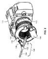
図1は、本開示の実施形態に係るカメラレンズの前方で物体を保持するためのシステムの側面図である。図2は、図1に示されるシステムの等角図である。図1及び図2を参照すると、取付ベース又はマウント100がカメラ104の前方でカメラレンズ102の前部に連結されている。取付リング100は、カメラレンズ102の前方に位置し得る1以上の効果棒106を支持するベースとして機能する。これらの図に示されている取付リング100は、丸いもの又は環状のものとして示されているが、取付リング100は、正方形、矩形、楕円など任意の形状を取り得るが、便宜上、本明細書では取付リング100とだけ言うこととする。後述するように、棒106は、カメラレンズに入る光を修正し、撮影者により制御可能な視覚効果を生成するような構造を有している。また、以下に述べるように、棒106は、撮影者により位置決めされた後も適切な位置に留まったままであるため、撮影者により作られる所望の効果を繰り返し再現することが可能である。
1 is a side view of a system for holding an object in front of a camera lens according to an embodiment of the present disclosure; FIG. FIG. 2 is an isometric view of the system shown in FIG. Referring to FIGS. 1 and 2, a mounting base or
図示された実施形態においては、棒106は、撮影者又は撮影者とともに作業する者により手で置かれ位置決めされ得る。棒106は、比較的強い磁石により適切な位置に保持される。図2に最も良く示されているように、棒106は、アーム108の磁気ソケット部に着座する磁気球状部152を含んでおり、アーム108は、ヨーク110のソケット部の中に着座する自身の球状部を有している。ヨーク110は、ベース100に磁気的に保持されるか、あるいは固定されている。このシステムの磁気球-ソケットインタフェイスのそれぞれにより界面での移動が可能となる。例えば、棒106の磁気球状部152は、アーム108のソケット部に対して移動することができ、位置決めすることができる。加えて、アーム108の磁気球状部は、ヨーク110のソケット部に対して移動することができ、位置決めすることができる。動作の際は、棒106とアーム108の磁性ボール-ソケットインタフェイスにより、撮影者は、カメラレンズ102に対してほとんどすべての位置に棒106を移動することが可能となる。そして、撮影者が棒106を離した際には、磁性ボール-ソケットインタフェイスの磁気作用は、撮影者によって設定された位置に棒を保持できる程に十分に強い。アーム108とヨーク110との間の磁性ボール-ソケットインタフェイスも同様に動作する。このため、撮影者は、必要とするところであればどこにでも棒を位置決めすることができ、撮影者が棒を配置した後も棒は適切な位置に留まるので、撮影者は、カメラレンズ102の前方の光路内のどこにどのように1以上の効果棒106を向けるかをほとんど完全に制御することができる。
In the illustrated embodiment, the
図3、図4、及び図5は、実施形態による、図1のシステムとともに使用され得る取付リング100、ヨークアセンブリ110、アームアセンブリ108、及び効果棒106を示している。図示された実施形態においては、取付リング100は、取付リング100の背面の嵌合フィルタネジ溝116(図5)とカメラレンズの標準フィルタネジ溝(図示せず)とを介してカメラレンズ102(図1)に取り付けられる。ある実施形態においては、取付リング100は、1以上の標準フィルタを受け入れるネジ前部112(図3)を追加で含み得る。このように、取付リング100は、自身のネジ溝116を介してカメラレンズの標準フィルタネジに取り付けられているにもかかわらず、取付リング100は標準フィルタを使用する選択肢を保持している。
Figures 3, 4, and 5 show a
取付リング100の取付ネジ溝116がカメラレンズのフィルタネジのサイズと異なるサイズを有している場合には、取付リング100をカメラレンズ102に連結するために1以上の標準フィルタアダプタリングを使用することができる。ある実施形態においては、取付リング100は、カメラレンズ102の任意のサイズのフィルタネジに適合する任意のサイズで製造され得る。他の実施形態においては、取付リング100は、限られた数のサイズで製造され、取付リング100の標準サイズのうちの1つに任意のカメラレンズ102を適合させるために標準フィルタアダプタリングが使用される。動作の際は、まず、アダプタリングをカメラレンズ102のフィルタネジに連結し、その後、取付リング100の取付ネジ溝116をアダプタの外縁(これもネジを含んでいる)に連結する。取付リングと(存在する場合には)アダプタのネジが締結されると、取付リング100がカメラレンズ102にしっかりと保持され、システムの他の部分に対して強固な基盤を提供する。取付リング100のある実施形態により、カメラレンズにしっかりと取り付けられたままでリングをカメラレンズ102に対して回転させることが可能になる。そのような実施形態は、取付リング100の取付ネジ溝116と取付リング自体との間に摺動面又は軸受面を含み得る。
One or more standard filter adapter rings are used to connect the
他の実施形態においては、取付リング100は、例えば、カメラの本体に取付リング100を紐でくくったり、クランプしたりするなど他の取付方法を用いてカメラの前部に固定され得る。他の実施形態においては、取付リング100は、多くのカメラの底部に位置する標準三脚ソケットに取り付けられるブラケットを含み得る。そのような実施形態においては、蝶ネジ又は他の固定具を使用して、取付リングがカメラレンズの前部近傍に位置するように取付リング100のブラケットをカメラに取り付けることができる。さらに他の実施形態は、カメラレンズの前部近傍に取付リング100を配置しつつ、ホットシュー又はコールドシュー(すなわち、フラッシュマウント)に取り付けられるブラケットを含んでいることがある。取付リング又は取付ベースをカメラ又はカメラレンズに取り付けることができるさらに他のものとしては、レールマウント、バヨネットマウント、及びネジ及び/又はボルトのような機械的マウントが考えられる。
In other embodiments, the mounting
取付リング100は、金属又は他の堅い材料から形成され得る。ある実施形態においては、取付リング100は、鋼のような磁性材料から製造されるか、あるいは、基材に連結される磁性面を含んでいる。取付リング100には、耐久性及び外観の観点からパウダーコーティングがなされていてもよい。図示された実施形態においては、取付リング100は、取付リング100の表面の大部分を占める凹状フロントリング114を含んでいる。フロントリング114は、図4に示されているように、内側リップと外側リップに対して凹んでいる。内側リップは、取付リング100のネジ部112から形成され得る。外側リップ118は、アームアセンブリ又は他のアクセサリを取り付け可能な機械的マウントとして機能するベース又は他の構造として作られている。
Mounting
取付リング100のフロントリング114は、その前面に取り付けられる1以上のヨークアセンブリ110を受け入れるようなサイズ及び構造を有している。取付リング100のフロントリングの内縁と外縁との間で、凹状の磁気的受容性のあるフロントリング114は、ヨークアセンブリ110の移動経路を保持し、ヨークアセンブリを再び位置決めしてヨークアセンブリ110に取り付けられた効果棒106の位置を調整しつつ、ヨークアセンブリが取付リングの前部の周囲で滑った場合においても、ヨークアセンブリを取付リング100にしっかりと取り付けた状態に維持することができる。
ある実施形態においては、図6に示されるように、ヨークアセンブリ110は、ヨークフレーム124と2つの磁気ソケット130とを含んでいる。それぞれのソケット130は、磁性ボールを受け入れる構造を有する幾分球状に凹んだ形状を形成する面取り磁石120と磁石プラグ122とを含み得る。磁石120と組み合わせて磁石プラグ122を用いることにより、特に強い磁気レシーバを作ることができる。ある実施形態においては、磁石120及び磁石プラグはそれぞれ6mmのサイズであるが、他のサイズ、例えばこれより小さいサイズ又は大きいサイズを用いてもよい。より大きなサイズの磁性ボールとソケットジョイントは大きな力を必要とするため、手で楽に棒106及びアーム108を動かすことができないことが考えられる。一方、より小さなサイズの磁性ボール及びソケットジョイントは、棒及びアームを適切な位置に保持するのに十分な磁力を有していないことが考えられる。
In one embodiment, the
それぞれのヨークアセンブリ110は、取付リングのフロントリング114に磁気的に結合され得る。ヨークアセンブリをフロントリング114に連結し続けるための磁力は、磁石120及び磁石プラグ122から生じるか、あるいはヨークアセンブリ110に取り付けられた他の磁石(図示せず)から生じ得る。好ましくは、それぞれのヨークアセンブリ110は、互いに離間した2以上の磁気ソケット130を含んでいる。アセンブリ110が1つの磁気ソケット130を含んでいる場合には磁石120が自由に回転し得るが、アセンブリ110ごとに互いに離間した2以上の磁気ソケット130を含めることにより、磁石120が自由に回転しないことを確実にすることができる。その代わりに、アセンブリ110ごとに2つの磁気ソケット130を含めることにより、アセンブリ110を取付リング100のフロントリング114に磁気的にしっかりと取り付けた状態のまま、撮影者が効果棒を自由に動かすことが可能となる。
Each
取付リング100のフロントリング114は、1以上のヨークアセンブリ110を受け入れることができるサイズとなっている。フロントリング114の経路の幅は、ヨークアセンブリ110の移動に適合するように選択され得る。換言すれば、フロントリングの経路の幅は、取付リング上でヨークアセンブリ110を位置決めする際に撮影者に選択肢を与えるほど十分に大きくてもよい。他の実施形態においては、経路の幅は、動きが制限された状態で1以上のヨークアセンブリ110を受け入れるのにちょうどの大きさとされ得る。さらに他の実施形態においては、取付リング100は、10個~20個の磁気ソケット(図示せず)でリング全体が完全に満たされていてもよい。そのような実施形態においては、システムは、別個のアセンブリ110を含んでいないであろうが、アーム108又は棒106を取付リング100上に恒久的に取り付けられるソケットの1つに直接取り付けてもよい。
磁気的に取り付けることに加えて、ある実施形態においては、一時的な接着材又は永久的な接着材あるいは機械的固定具を用いてヨークアセンブリ110を取付リング100に取り付けてもよい。
In addition to magnetic attachment, in some embodiments, temporary or permanent adhesives or mechanical fasteners may be used to attach
図7を参照すると、アームアセンブリ108は、ヨークアセンブリ110と連係して使用され得る。図示されたアームアセンブリ108は、フレーム140と、磁気球状部142と、磁気ソケット部148とを含んでいる。図6のヨークアセンブリ110と同様に、アームアセンブリ108の磁気ソケット部148は、小さな中空円筒状磁石144と小さな磁石プラグ146とを含んでいる。ある実施形態においては、アームアセンブリ108の磁石144とプラグ146は、ヨークアセンブリ110の磁石120とプラグ120と同じサイズである。アームアセンブリ108のフレーム130の長さは、実施の仕様に合わせてもよい。また、図1のシステムの1組の構成要素は、異なる長さの複数のアームアセンブリ108を含んでいてもよく、これらにより撮影者にはさらなる柔軟性が提供される。
Referring to FIG. 7,
動作の際は、アームアセンブリの磁気球状部148は、ヨークアセンブリ110の磁気ソケット部130のうちの1つに挿入される。その後、棒106、特に棒106の磁気球状部152が、アームアセンブリ108の磁気ソケット部148に挿入される。この2つの別個の磁気ボール-ソケットジョイントとの組み合わせ(図1及び図2に示されているように、アームアセンブリ108へのヨークアセンブリ110の結合部と、アームアセンブリ108と棒106との結合部)により、撮影者には、カメラレンズ102に対して様々な効果棒を位置決めする際に多くの自由度が与えられる。また、それぞれのヨークアセンブリ110は少なくとも2つの磁気ソケット部130を含んでいるので、これにより、それぞれのヨークアセンブリ110が、それぞれ別個に撮影者によって位置決め可能な2つの別個の効果棒106を支持することが可能となる。さらに、棒106同士を重ねて又は部分的に重ねて棒106の効果を組み合わせてもよい。さらにまた、それぞれの追加のヨークアセンブリ110が、追加の2つの棒106を支持し、取付リング100上に多くのヨークアセンブリ110を配置するためのスペースがある。したがって、撮影者は、カメラレンズ102に入射する光に対してそれぞれ効果を与える効果棒の無限に近い組み合わせを選択及び位置決めすることにより様々な美的なコントロールを行うことができ、これにより、撮影者は自分のイメージをどのように作り上げるのかについて効果的に完全に把握することができる。
In operation, the arm assembly's
上述した実施形態は、磁気ボール-ソケット関節ジョイント構造であったが、他の実施形態においては他の関節ジョイント構造を用いることができる。例えば、そのような関節ジョイント構造の1つは、効果棒106を適切な位置に移動して位置決めされた後にその位置に保持させることを可能にする2つの別個の部品の間の摩擦ジョイント又はラチェットジョイントのような任意の機械的関節ジョイントから構成することができる。さらに、関節ジョイント構造として述べられているものは、実際には、関節構造ではないが、効果棒106を位置決めされた後に保持される位置に置くように操作され得る単一の材料部品から構成されていてもよい。例えば、効果棒106に連結されるアーム又は他の構造は、移動された後にその位置を保持する金属ワイヤあるいはプラスチック又は他の材料でコーティングされた金属ワイヤのような屈曲可能な又は曲げやすい材料から構成されていてもよい。
Although the embodiment described above was a magnetic ball-and-socket articulated joint structure, other articulated joint structures can be used in other embodiments. For example, one such articulated joint structure is a friction joint or ratchet between two separate parts that allows the
図8は、実施形態に係る図1のシステムとともに使用され得る効果棒106の平面図である。上述したように、効果棒106は、ハンドル154と効果部156との間に位置する磁気球状部152を含み得る。棒106の効果部156は、概して、対象物からの光がカメラレンズ102に入射する際にその光を修正するために使用される。多くの実施形態においては、効果部156は、それぞれ得られる画像に様々な効果を与える水晶、ガラス、又はプラスチックから形成される。効果部156は、例えば、プリズムや部分プリズム、丸形状、又は半球状などの異なる形状から形成されていてもよい。ある実施形態においては、効果部156は、ハンドル154にクランプされた回折フィルムのようなフィルムであってもよい。特定の実施形態においては、棒の効果部156は、水晶槍、水晶シーホース、円筒レンズ、回折グレーティングフィルム、縁部に小平面を有する光学窓、40/60/80度三角形プリズム、等辺三角形プリズム、光学窓リング、ミラー又はミラー窓、ロッド又はチューブ、色付き又はパターン付きフィルム、液体又は非晶質固体で満たされた容器、透明液晶ディスプレイのうち1つ以上を含み得る。
FIG. 8 is a plan view of an
他の実施形態においては、棒106の効果部156は、カメラレンズ102に入射する光に対して不透明な様々な形状を含み得る。そのような不透明な棒106を移動させることで、撮影者は、光のない状態を制御可能とすることで影、陰、閉塞や他の効果を作り出すことができる。
In other embodiments,
さらに他の実施形態においては、効果棒106は、その効果部156に光源を含んでいてもよい。この光源は、例えば電池により駆動されてもよく、太陽光により駆動されていてもよい。他の例においては、光源は、グロースティックのような化学発光体であってもよい。効果棒106が光源を含んでいる実施形態においては、撮影者は、得られる画像の特定の部分に光源を追加することができる。簡単に移動でき、移動された後は適切な位置に保持される棒106に光源を配置することにより、以前は得られなかった多くの創造的なコントロールが撮影者に提供される。
In still other embodiments, the
上記で述べた実施形態は棒106を手で操作しているが、他の実施形態においては、棒アセンブリ106のハンドル154をモータ駆動又は機械駆動アクセサリに挿入することができ、これにより、ユーザが調整可能な速度で物体が移動し、周方向移動、径方向移動、ピッチ移動、ヨー移動、ロール移動、及び写真レンズからの距離移動が可能になる。そのような実施形態においては、ユーザによりプログラムされた所定の経路に合致するように移動を行うことができる。
Although the embodiments described above have manually operated
ある実施形態においては、棒アセンブリ106は、カメラに取り付けられた電話内の加速度計に基づいてモータ駆動により移動され得る。これにより、撮像しているカメラをパンニングしたり、上げたり、下げたりすることと連係させて画像を通して考えられる動作の中でも物体をスイープ及び回転させる能力をユーザに与えることができる。
In one embodiment, the
他の実施形態においては、効果棒106のモータ駆動による移動は、静止画又は動画を撮影しているカメラによって決定される。このカメラは、有線又は無線により棒アセンブリの動作を決定するモータと通信し、カメラの移動に基づいてカメラの前方に置かれる物体又は光に対して自然な動き又は明確に人工的な動きを与える。
In other embodiments, the motorized movement of the
図9を参照すると、開示されている実施形態は、アーム108及び棒106をフィルタネジのないカメラとレンズの組み合わせに接続することができる自身の磁気ソケットを有する取付機構160をさらに含んでいる。カメラは、従来のフィルムカメラ又はデジタルポイントアンドシュートカメラ又は一眼レフカメラのようなスタンドアロン型のカメラ、あるいは、携帯デバイス、コンピュータ、あるいは電話164のような他のデバイスに一体化されたカメラであってもよい。この取付機構は、様々な実施形態において、ヨークアセンブリ110において使用されたものに類似する磁気ソケット130とのクランプの形態を取ることができ、あるいは電話ケースに一体化することができ、あるいは元々は補助レンズを取り付けることを意図したバヨネット又はネジ機構の形態の既存のレンズマウントを利用することができる。他の実施形態においては、取付機構160は、一時的な接着材又は永久的な接着材、摩擦マウントなどのようなデバイスにカメラレンズの光路に棒106を配置することができるように取り付ける他の方法を使用することができる。
Referring to FIG. 9, the disclosed embodiment further includes a
本明細書で述べたように、本発明の実施形態は、カメラレンズの前方で物体を保持するためのシステムに向けられている。上述した様々な実施形態の要素は、周方向の調整、径方向の調整、ピッチ調整、ヨー調整、ロール調整、及び写真レンズ調整からの距離を可能にし、レンズフィルタネジにより取り付けられるベース、クランプにより取り付けられるベース、及びラックにより取り付けられるベースに機械的にテンションが付与されたボール及びソケットシステムを組み込んだ磁気ベースシステムを提供する。上述したシステムは、フィルタネジを有するレンズ、ネジのないレンズ、より大きな支持システムの一部であるレンズを用いたものに対する芸術的コントロールを可能にする。カメラのレンズの前方でシステムを取り付けるすべての方法が考えられる。これらの取付オプションは、カメラ及びレンズのユーザに対して追加の芸術的なコントロールを提供し、現在入手可能なフィルタシステムで、あるいは、カメラレンズの前方に物体を配置するために現在用いられている方法では作成することができない再現可能な画像をユーザが生成することを可能にする。 As described herein, embodiments of the present invention are directed to systems for holding an object in front of a camera lens. The elements of the various embodiments described above allow for circumferential adjustment, radial adjustment, pitch adjustment, yaw adjustment, roll adjustment, and distance from the photographic lens adjustment, base attached by lens filter screws, by clamps. A magnetic base system incorporating a mounted base and a ball and socket system mechanically tensioned to the base mounted by a rack is provided. The system described above allows artistic control over lenses with filter threads, lenses without threads, and with lenses that are part of a larger support system. All ways of mounting the system in front of the camera lens are conceivable. These mounting options provide additional artistic control to the user of the camera and lens and are currently used in currently available filter systems or to place objects in front of the camera lens. It allows the user to create reproducible images that cannot be created by the method.
したがって、カメラレンズの前方で物体を保持するためのシステムの少なくともいくつかの実施形態は、磁気的に受入可能な取付リングと、磁気的に受入可能なリングを様々な物体に接続するために使用される少なくとも1つの磁石とを含んでいる。また、カメラ上に取り付けられる取付リングは、カメラレンズの周囲かつその前方で物体を保持する磁石を受け入れる部分を含んでいる。 Accordingly, at least some embodiments of a system for holding an object in front of a camera lens include a magnetically receptive mounting ring and use to connect the magnetically receptive ring to various objects. and at least one magnet that is connected to the magnet. A mounting ring mounted on the camera also includes a portion that receives a magnet that holds an object around and in front of the camera lens.
システムの少なくともいくつかの実施形態においては、物体を磁気的に受入可能なリングに固定するために使用される磁石は、最大表面積と接触し、物体のハンドルとユニバーサルクリップに一体化される磁気的に受入可能な球状面にしっかりと保持するために、内側面取りと貫通孔を有する円筒形である。これにより、調整が完了したときの物体の位置を維持しつつ、物体をシステムに取り付けて移動させることが可能になる。したがって、物体のハンドル及びユニバーサルクリップの磁気的に受入可能な球状部のテンションを上げるために、これらの中空面取り円筒磁石は、磁石の中空部をほぼ満たす磁気的に受入可能な円筒プラグを組み込んでいてもよい。これらの磁気的に受入可能な円筒プラグは、延長アーム及び他のアクセサリの円筒面だけではなく、ハンドルの球面を押し付け、ハンドルと他のアクセサリ上のテンションを上げ、さらに、調整が完了したときに物体が確実に固定されたままとなる。 In at least some embodiments of the system, the magnet used to secure the object to the magnetically receptive ring contacts the largest surface area and is integrated into the handle of the object and the universal clip. It is cylindrical with internal chamfers and through-holes to hold it securely on a spherical surface receptive to the. This allows the object to be attached to the system and moved while maintaining the position of the object when the adjustment was completed. Therefore, these hollow chamfered cylindrical magnets incorporate a magnetically receptive cylindrical plug that substantially fills the hollow of the magnet in order to increase the tension of the magnetically receptive sphere of the object's handle and universal clip. You can These magnetically receptive cylindrical plugs press against the spherical surface of the handle as well as the cylindrical surface of the extension arm and other accessories, increasing the tension on the handle and other accessories, and further, when the adjustment is complete. The object remains securely fixed.
上述した例及び説明に基づくと、本発明の実施形態は、磁石、ピン、ボルト、クランプ、又は他の機械的手段により、物体、光学系、ライト、モータなどをカメラレンズの前方に取り付けることを可能にする。ある実施形態においては、システムに取り付けられた関節機構は、アクセサリを適切な位置に保持し、効果を生じさせる物体の操作を可能にするためにカメラレンズの前部に取り付けられる。これらの物体は、磁性、ネジ、クランプ、接着材、又は他の機械的手段により、関節機構にしっかりと取り付けられ、また関節機構から取り外される。 Based on the examples and explanations given above, embodiments of the present invention provide for mounting objects, optics, lights, motors, etc. in front of the camera lens by magnets, pins, bolts, clamps, or other mechanical means. to enable. In one embodiment, an articulation mechanism attached to the system is attached to the front of the camera lens to hold the accessory in place and allow manipulation of the object to produce the effect. These objects are securely attached to and detached from the articulation mechanism by magnetism, screws, clamps, adhesives, or other mechanical means.
本開示の様々な実施形態は、効果を生じさせる物体の周方向の調整、径方向の調整、ピッチ調整、ヨー調整、ロール調整、及び写真レンズ調整からの距離を可能にするために、関節機構を利用した磁石、摩擦嵌めボール及びソケット、ラチェットヒンジ、又は他の手段若しくは機構を提供する。 Various embodiments of the present disclosure use an articulation mechanism to allow circumferential adjustment, radial adjustment, pitch adjustment, yaw adjustment, roll adjustment, and distance from photographic lens adjustment of the object to produce an effect. magnets, friction fit balls and sockets, ratchet hinges, or other means or mechanisms utilizing
様々な実施形態は、他の物体及び/又は関節アームとともに、あるいは他の物体及び/又は関節アームとは別個に使用される伝統的な丸い又は四角いフィルタを取り付けることを可能にする。 Various embodiments allow attachment of traditional round or square filters for use with other objects and/or articulated arms or separately from other objects and/or articulated arms.
様々な実施形態は、関節アーム、物体又は、効果を生じさせる物体、棒、又は関節アームに連結される光源を移動又は回転させるためのモータを取り付けることを可能にする。 Various embodiments allow the attachment of motors to move or rotate an articulated arm, an object, or a light source coupled to an effect-producing object, rod, or articulated arm.
様々な実施形態は、照明されていない物体を使用する場合とは異なる又はより強い効果を生成する目的でシステム内に保持された物体に光を投光するための照明デバイスを取り付けることを可能にする。あるいは、取り付けられた照明デバイスを写真対象物を照明するために使用してもよい。 Various embodiments enable the attachment of lighting devices to project light onto objects held within the system for the purpose of producing different or stronger effects than using unilluminated objects. do. Alternatively, an attached lighting device may be used to illuminate the photographic subject.
取り付けられた照明デバイスの他の用途は、付加的な光がフレア、ゴースト、及びコントラスト低下を生じさせるのでそのような効果を生じさせるために、カメラレンズに光を投光することである。照明デバイスは、関節アームを利用して生成する光の位置及び方向を操作するオプションを有するシステムに取り付けられる。 Another application for attached lighting devices is to project light onto a camera lens to produce flare, ghosting, and contrast loss as the additional light produces such effects. The lighting device is attached to the system with the option of manipulating the position and direction of the light it produces utilizing the articulated arm.
本説明は特定の特徴を参照している。本明細書の開示は、これらの特定の特徴の考えられるすべての組み合わせを含むものであることは理解すべきである。例えば、特定の側面又は実施形態の文脈において特定の特徴が開示されている場合には、考えられる範囲においてその特徴は他の側面及び実施形態の文脈においても用いることができる。 This description refers to specific features. It is to be understood that the disclosure herein encompasses all possible combinations of these specific features. For example, if a particular feature is disclosed in the context of a particular aspect or embodiment, that feature can also be used in the context of other aspects and embodiments to the extent contemplated.
また、本出願において2以上の規定ステップ又は動作を有する方法に言及する場合には、その規定ステップ又は動作は、文脈がその可能性を排除していない限り、任意の順序で行われてもよく、同時に行われてもよい。 Also, when this application refers to a method having more than one defined step or action, the defined steps or actions may be performed in any order, unless the context precludes the possibility. , may be performed simultaneously.
さらに、「備える」、「含む」及びこれらと文法的に等価な用語は、本出願においては、他の構成要素、特徴、ステップ、プロセス、動作などが必要に応じて存在することを意味するものとして使用される。例えば、構成要素A、B、及びCを「有する」又は「備える」物は、構成要素A、B、及びCだけを含んでいてもよいし、構成要素A、B、及びCとともに1以上の他の構成要素を含んでいてもよい。 Further, the terms "comprising," "including," and grammatical equivalents, as used in this application, mean that the optional presence of other elements, features, steps, processes, acts, etc. used as For example, an article that "comprises" or "comprising" components A, B, and C may include only components A, B, and C, or together with components A, B, and C, one or more It may contain other components.
本明細書で開示される技術の例示的な例が以下に述べられる。本技術の実施形態は、以下に述べる実施例のいずれか1つ以上及びその組み合わせを含み得る。 Illustrative examples of the technology disclosed herein are described below. Embodiments of the present technology may include any one or more of the examples described below and combinations thereof.
実施例1は、カメラレンズの光路内で物体の位置を維持するためのシステムを含み、カメラレンズに取り付けられるような構造を有する取付ベースと、上記カメラレンズの上記光路に置かれた場合に光を修正する1以上の物体と、上記取付ベースと上記1以上の物体との間に配置され、上記1以上の物体を上記カメラレンズの上記光路に移動可能に配置できるような構造を有する少なくとも1つの関節ジョイント構造とを備える。 Example 1 includes a system for maintaining the position of an object within the optical path of a camera lens, a mounting base configured to be attached to a camera lens, and a mounting base configured to attach to the optical path of the camera lens. and at least one object disposed between the mounting base and the one or more objects, and having a structure that allows the one or more objects to be movably positioned in the optical path of the camera lens. and an articulated joint structure.
実施例2は、上記関節ジョイント構造は、周方向の調整、径方向の調整、ピッチ調整、ヨー調整、ロール調整、及び上記1以上の物体のうち少なくとも1つの上記カメラレンズからの距離からなる群のうち1つ以上の調整を可能にする、実施例1のカメラレンズの光路内で物体を保持するためのシステムを含んでいる。 In a second embodiment, the articulated joint structure comprises a group consisting of circumferential adjustment, radial adjustment, pitch adjustment, yaw adjustment, roll adjustment, and distance from the camera lens of at least one of the one or more objects. includes a system for holding an object within the optical path of the camera lens of Example 1 that allows adjustment of one or more of
実施例3は、上記1以上の物体は、位置決めされた後にその位置を維持する、先行する実施例のいずれかのカメラレンズの光路内で物体を保持するためのシステムを含んでいる。 Example 3 includes a system for holding an object within the optical path of a camera lens of any of the preceding examples, wherein the one or more objects maintain their position after being positioned.
実施例4は、上記関節ジョイント構造は、上記1以上の物体を手で位置決めできるような構造を有する、先行する実施例のいずれかのカメラレンズの光路内で物体を保持するためのシステムを含んでいる。 Example 4 includes the system for holding an object within the optical path of a camera lens of any of the preceding examples, wherein said articulated joint structure has a structure such that said one or more objects can be manually positioned. I'm in.
実施例5は、上記取付ベースは、上記カメラレンズに取り付けるための第1組のネジと、ネジ付きフィルタを受け入れるための第2組のネジとを備える、先行する実施例のいずれかのカメラレンズの光路内で物体を保持するためのシステムを含んでいる。 Example 5 is the camera lens of any preceding example, wherein the mounting base comprises a first set of screws for attaching to the camera lens and a second set of screws for receiving a threaded filter. includes a system for holding an object within the optical path of the
実施例6は、上記1以上の物体のうち少なくとも1つに連結されるモータであって、上記連結された物体を上記カメラレンズに対して移動するような構造を有するモータをさらに備える、先行する実施例のいずれかのカメラレンズの光路内で物体を保持するためのシステムを含んでいる。 Example 6 further comprises a motor coupled to at least one of the one or more objects, the motor configured to move the coupled object relative to the camera lens, preceding. Any of the embodiments includes a system for holding an object within the optical path of a camera lens.
実施例7は、さらにプログラム可能なモータコントローラをさらに備える、実施例6のカメラレンズの光路内で物体を保持するためのシステムを含んでいる。 Example 7 includes the system for holding an object within the optical path of the camera lens of Example 6, further comprising a programmable motor controller.
実施例8は、上記プログラム可能なモータコントローラは、上記カメラレンズの移動に基づいて、あるいは上記カメラレンズにより生成された画像内での対象物の移動に基づいて上記モータを制御する構造を有する、実施例7のカメラレンズの光路内で物体を保持するためのシステムを含んでいる。 Embodiment 8 is configured such that the programmable motor controller controls the motor based on movement of the camera lens or movement of an object within an image produced by the camera lens. Example 7 includes a system for holding an object within the optical path of the camera lens.
実施例9は、上記1以上の物体のうち少なくとも1つは、投光用の光源を含む、先行する実施例のいずれかのカメラレンズの光路内で物体を保持するためのシステムを含んでいる。 Example 9 includes a system for holding an object within the optical path of a camera lens of any of the preceding examples, wherein at least one of said one or more objects includes a light source for illumination. .
実施例10は、上記光源は、写真対象物を照明するような構造を有する、先行する実施例のいずれかのカメラレンズの光路内で物体を保持するためのシステムを含んでいる。 Example 10 includes a system for holding an object within the optical path of a camera lens of any of the preceding examples, wherein the light source is structured to illuminate the photographic object.
実施例11は、上記光源は、光を上記カメラレンズに投光するような構造を有する、先行する実施例のいずれかのカメラレンズの光路内で物体を保持するためのシステムを含んでいる。 Example 11 includes a system for holding an object within the optical path of a camera lens of any of the preceding examples, wherein the light source is structured to project light onto the camera lens.
実施例12は、上記1以上の物体のうち少なくとも1つは、水晶、液晶、ガラス、金属、又はプラスチックから構成される、先行する実施例のいずれかのカメラレンズの光路内で物体を保持するためのシステムを含んでいる。 Example 12 holds an object within the optical path of the camera lens of any preceding example, wherein at least one of said one or more objects is composed of quartz, liquid crystal, glass, metal, or plastic. contains a system for
実施例13は、上記1以上の物体のうち少なくとも1つは、回折グレーティングフィルムである、先行する実施例のいずれかのカメラレンズの光路内で物体を保持するためのシステムを含んでいる。 Example 13 includes a system for holding an object within the optical path of a camera lens of any of the preceding examples, wherein at least one of the one or more objects is a diffractive grating film.
実施例14は、上記1以上の物体のうち少なくとも1つは、色付きジェルである、先行する実施例のいずれかのカメラレンズの光路内で物体を保持するためのシステムを含んでいる。 Example 14 includes the system for holding an object within the optical path of a camera lens of any of the preceding examples, wherein at least one of the one or more objects is a colored gel.
実施例15は、上記関節ジョイント構造は磁気ソケットを含む、先行する実施例のいずれかのカメラレンズの光路内で物体を保持するためのシステムを含んでいる。 Example 15 includes a system for holding an object within the optical path of a camera lens of any of the preceding examples, wherein the articulated joint structure includes a magnetic socket.
実施例16は、上記関節ジョイント構造は、取付ベースに磁気的に連結されるような構造を有する1対の磁気ソケットを含む、先行する実施例のいずれかのカメラレンズの光路内で物体を保持するためのシステムを含んでいる。 Embodiment 16 is any of the preceding embodiments, wherein the articulating joint structure includes a pair of magnetic sockets configured to be magnetically coupled to the mounting base for holding an object within the optical path of the camera lens of any of the preceding embodiments. contains a system for
実施例17は、上記関節ジョイント構造は、上記磁気ソケットに磁気的に保持されるような構造を有する磁性ボールをさらに含む、先行する実施例のいずれかのカメラレンズの光路内で物体を保持するためのシステムを含んでいる。 Example 17 holds an object in the optical path of a camera lens of any of the preceding examples, wherein said articulating joint structure further comprises a magnetic ball configured to be magnetically retained in said magnetic socket. contains a system for
実施例18は、上記磁性ボールは、上記1以上の物体のうち1つに取り付けられる、先行する実施例のいずれかのカメラレンズの光路内で物体を保持するためのシステムを含んでいる。 Example 18 includes the system for holding an object within the optical path of a camera lens of any of the preceding examples, wherein said magnetic ball is attached to one of said one or more objects.
実施例19は、上記磁性ボールは、追加で自身の磁気ソケットを含むアームに取り付けられる、先行する実施例のいずれかのカメラレンズの光路内で物体を保持するためのシステムを含んでいる。 Example 19 includes a system for holding an object within the optical path of a camera lens of any of the previous examples, wherein the magnetic ball is additionally attached to an arm containing its own magnetic socket.
実施例20は、上記関節ジョイント構造は、磁性ボール及び磁気ソケットをそれぞれ含む少なくとも2つのアームを含む、先行する実施例のいずれかのカメラレンズの光路内で物体を保持するためのシステムを含んでいる。 Example 20 includes a system for holding an object within the optical path of a camera lens of any of the preceding examples, wherein the articulated joint structure includes at least two arms each including a magnetic ball and a magnetic socket. there is
実施例21は、上記関節ジョイント構造は、機械的関節ジョイントを含む、先行する実施例のいずれかのカメラレンズの光路内で物体を保持するためのシステムを含んでいる。 Example 21 includes a system for holding an object within the optical path of a camera lens of any of the preceding examples, wherein the articulated joint structure comprises a mechanical articulated joint.
実施例22は、上記関節ジョイント構造は、摩擦ジョイント又はラチェットジョイントを含む、実施例21のカメラレンズの光路内で物体を保持するためのシステムを含んでいる。 Example 22 includes a system for holding an object within the optical path of the camera lens of Example 21, wherein the articulated joint structure comprises a friction joint or a ratchet joint.
実施例23は、上記取付ベースは、摩擦マウントを用いて上記カメラレンズに取り付けられる、先行する実施例のいずれかのカメラレンズの光路内で物体を保持するためのシステムを含んでいる。 Example 23 includes a system for holding an object within the optical path of the camera lens of any of the preceding examples, wherein the mounting base is attached to the camera lens using a friction mount.
実施例24は、上記取付ベースは、クランプマウントを用いて上記カメラレンズに取り付けられる、先行する実施例のいずれかのカメラレンズの光路内で物体を保持するためのシステムを含んでいる。 Example 24 includes the system for holding an object within the optical path of the camera lens of any of the preceding examples, wherein the mounting base is attached to the camera lens using a clamp mount.
実施例25は、上記取付ベースは、バヨネットマウントを用いて上記カメラレンズに取り付けられる、先行する実施例のいずれかのカメラレンズの光路内で物体を保持するためのシステムを含んでいる。 Example 25 includes the system for holding an object within the optical path of the camera lens of any of the preceding examples, wherein the mounting base is attached to the camera lens using a bayonet mount.
実施例26は、上記取付ベースは、カメラの三脚マウントに取り付けられたベースサポートを介して上記カメラレンズに取り付けられる、先行する実施例のいずれかのカメラレンズの光路内で物体を保持するためのシステムを含んでいる。 Example 26 is for holding an object within the optical path of a camera lens of any of the preceding examples, wherein said mounting base is attached to said camera lens via a base support attached to a camera tripod mount. contains the system.
実施例27は、上記取付ベースは、カメラのホットシュー又はコールドシューに取り付けられたベースサポートを介して上記カメラレンズに取り付けられる、先行する実施例のいずれかのカメラレンズの光路内で物体を保持するためのシステムを含んでいる。 Example 27 is a method for holding an object in the optical path of a camera lens of any of the preceding examples, wherein the mounting base is attached to the camera lens via a base support attached to a hot shoe or cold shoe of the camera. contains a system for
実施例28は、上記取付ベースは、機械的固定具を介して上記カメラレンズに取り付けられる、先行する実施例のいずれかのカメラレンズの光路内で物体を保持するためのシステムを含んでいる。 Example 28 includes the system for holding an object within the optical path of the camera lens of any of the preceding examples, wherein the mounting base is attached to the camera lens via mechanical fasteners.
実施例29は、上記取付ベースは、レールマウントを介して上記カメラレンズに取り付けられる、先行する実施例のいずれかのカメラレンズの光路内で物体を保持するためのシステムを含んでいる。 Example 29 includes a system for holding an object within the optical path of the camera lens of any of the preceding examples, wherein the mounting base is attached to the camera lens via a rail mount.
実施例30は、上記取付ベースは、上記カメラレンズにボルト締結される、先行する実施例のいずれかのカメラレンズの光路内で物体を保持するためのシステムを含んでいる。 Example 30 includes a system for holding an object within the optical path of the camera lens of any of the preceding examples, wherein the mounting base is bolted to the camera lens.
説明のために特定の実施形態が図示され述べられてきたが、本開示の精神及び範囲を逸脱することなく、様々な変更が可能であることは理解されよう。 While particular embodiments have been illustrated and described for purposes of explanation, it will be appreciated that various changes can be made therein without departing from the spirit and scope of the disclosure.
Claims (20)
カメラレンズに取り付けられるような構造を有する取付ベースと、
前記カメラレンズの前記光路に置かれた場合に光を修正する1以上の物体と、
前記取付ベースと前記1以上の物体との間に配置され、前記1以上の物体を前記カメラレンズの前記光路に移動可能に配置できるような構造を有する少なくとも1つの関節ジョイント構造と
を備える、システム。 A system for maintaining the position of an object within the optical path of a camera lens, comprising:
a mounting base having a structure to be mounted on a camera lens;
one or more objects that modify light when placed in the optical path of the camera lens;
at least one articulated joint structure disposed between the mounting base and the one or more objects and configured to movably position the one or more objects in the optical path of the camera lens. .
Applications Claiming Priority (3)
| Application Number | Priority Date | Filing Date | Title |
|---|---|---|---|
| US201962862704P | 2019-06-18 | 2019-06-18 | |
| US62/862,704 | 2019-06-18 | ||
| PCT/US2020/038545 WO2020257529A1 (en) | 2019-06-18 | 2020-06-18 | System for holding objects at the front of a camera lens |
Publications (2)
| Publication Number | Publication Date |
|---|---|
| JP2022542213A true JP2022542213A (en) | 2022-09-30 |
| JPWO2020257529A5 JPWO2020257529A5 (en) | 2023-06-23 |
Family
ID=74038559
Family Applications (1)
| Application Number | Title | Priority Date | Filing Date |
|---|---|---|---|
| JP2021575916A Pending JP2022542213A (en) | 2019-06-18 | 2020-06-18 | A system for holding an object in front of a camera lens |
Country Status (5)
| Country | Link |
|---|---|
| US (2) | US20200401023A1 (en) |
| EP (1) | EP3987356A4 (en) |
| JP (1) | JP2022542213A (en) |
| CN (1) | CN114424117A (en) |
| WO (1) | WO2020257529A1 (en) |
Family Cites Families (22)
| Publication number | Priority date | Publication date | Assignee | Title |
|---|---|---|---|---|
| GB710967A (en) * | 1950-10-11 | 1954-06-23 | Kurt Kirchhoff | Improvements in or relating to lens attachments for photographic cameras |
| US5208624A (en) * | 1991-10-10 | 1993-05-04 | Sony Corporation Of America | Camera lens and filter adapter assembly |
| US5550610A (en) * | 1995-08-09 | 1996-08-27 | Demarco; Frank G. | System for creating special effect images in the out-of-focus highlights of photographs |
| JPH10274799A (en) * | 1997-03-31 | 1998-10-13 | Inon:Kk | Ring light stroboscope provided with rotary light shielding plate for light balance and light quantity control |
| US6033130A (en) * | 1997-10-27 | 2000-03-07 | Olympus Optical Co., Ltd. | Lens cover and a lens cover support assembly mounted external to a lens barrel |
| KR20000004291A (en) * | 1998-06-30 | 2000-01-25 | 안승균 | Apparatus for supporting a filter for a camera lens |
| JP4306913B2 (en) * | 2000-03-02 | 2009-08-05 | マミヤ・デジタル・イメージング株式会社 | Polarizing filter guide device |
| JP2003050421A (en) * | 2001-08-06 | 2003-02-21 | Tamron Co Ltd | Camera equipped with polarizing filter and polarizing filter device |
| US7194200B1 (en) * | 2005-01-25 | 2007-03-20 | Behlow Charles L | Camera attachment for compressing pliant objects during photography thereof |
| US7296902B2 (en) * | 2005-07-27 | 2007-11-20 | Christie Digital Systems Canada, Inc. | Opto-mechanical filter for blending of images from a digital projector |
| KR100718241B1 (en) * | 2006-02-06 | 2007-05-15 | 이용주 | Filter holder for lenz of camera |
| CN200962174Y (en) * | 2006-09-29 | 2007-10-17 | 易文清 | Camera random natural light reflection board |
| US8620152B1 (en) | 2011-11-09 | 2013-12-31 | Rex Martin | Auxiliary lens positioning system for portable cameras |
| JP5207094B1 (en) * | 2012-04-09 | 2013-06-12 | 公善 富田 | Monopod free head for long focus lens |
| JP6037262B2 (en) * | 2012-04-20 | 2016-12-07 | 福田 英樹 | Camera adapter for adjusting the amount of strobe light |
| TW201430438A (en) * | 2013-01-29 | 2014-08-01 | Ingrasys Technology Inc | Camera module |
| US8774618B1 (en) * | 2013-10-04 | 2014-07-08 | Michael Muzila | Adjustable camera flash mounting device |
| DE202013104541U1 (en) | 2013-10-08 | 2013-10-28 | Arnold & Richter Cine Technik Gmbh & Co. Betriebs Kg | Compendium for a film or video camera |
| TWM481558U (en) * | 2014-01-13 | 2014-07-01 | Beseye Cloud Security Co Ltd | Monitoring device |
| US9939714B1 (en) * | 2017-03-28 | 2018-04-10 | Andrew Ryan Matthews | Intra-oral camera |
| CN207148500U (en) * | 2017-04-28 | 2018-03-27 | 魏志凌 | A kind of camera lens support |
| CN208621888U (en) * | 2018-07-24 | 2019-03-19 | 杭州海康威视数字技术股份有限公司 | Lens aperture and image acquisition equipment |
-
2020
- 2020-06-18 JP JP2021575916A patent/JP2022542213A/en active Pending
- 2020-06-18 CN CN202080044096.5A patent/CN114424117A/en active Pending
- 2020-06-18 WO PCT/US2020/038545 patent/WO2020257529A1/en unknown
- 2020-06-18 US US16/905,795 patent/US20200401023A1/en not_active Abandoned
- 2020-06-18 EP EP20827885.3A patent/EP3987356A4/en active Pending
-
2023
- 2023-07-31 US US18/228,588 patent/US20230375905A1/en active Pending
Also Published As
| Publication number | Publication date |
|---|---|
| US20230375905A1 (en) | 2023-11-23 |
| WO2020257529A1 (en) | 2020-12-24 |
| EP3987356A1 (en) | 2022-04-27 |
| CN114424117A (en) | 2022-04-29 |
| EP3987356A4 (en) | 2023-06-28 |
| US20200401023A1 (en) | 2020-12-24 |
Similar Documents
| Publication | Publication Date | Title |
|---|---|---|
| CN103353664B (en) | Lens assembly | |
| CN105549197B (en) | Lens cap adapter for image capture device | |
| EP1317687B1 (en) | PHOTOGRAPHING SYSTEM FOR PRODUCING ViRTUAL REALITY EDITING | |
| TW200532349A (en) | Optical equipment converter | |
| CN1046609C (en) | Camoorder with detachable and rotatable LCD assembly having tiltable LCD viewfinder and strap body | |
| JP2010117718A5 (en) | ||
| JP2012042902A (en) | Lens hood | |
| JP2022542213A (en) | A system for holding an object in front of a camera lens | |
| JP5507884B2 (en) | All-view panorama stereoscopic viewer | |
| US4733960A (en) | Lens adapter for creating photographically reproduced designs with turnable mirror tube | |
| CN205028017U (en) | Image location remote control auto heterodyne appearance | |
| CN106707664B (en) | Image remote position controlled self-timer instrument | |
| US9451136B2 (en) | Array camera shutter | |
| US20180164666A1 (en) | Articulating Projector Mount | |
| US6628458B1 (en) | Microscope with improved camera mount and illumination system | |
| JP2006119554A (en) | Camera fixture | |
| CN216577929U (en) | Lens gluing centering support | |
| CN2147550Y (en) | Wantonly image changeable sleeve lens | |
| KR20200017892A (en) | Mounting apparatus of digital camera for hairdressing | |
| CN112346243B (en) | Glasses | |
| CN2217228Y (en) | Arrangement for special procedure for taking photographs | |
| CN2828865Y (en) | Camera flash structure with image displaying function | |
| KR200362033Y1 (en) | Multi-Purpose Imaging Device | |
| CN100585484C (en) | Image photograph method with painting effect and special-purpose photo image refraction apparatus | |
| JPWO2020257529A5 (en) |
Legal Events
| Date | Code | Title | Description |
|---|---|---|---|
| A521 | Request for written amendment filed |
Free format text: JAPANESE INTERMEDIATE CODE: A523 Effective date: 20220311 |
|
| A521 | Request for written amendment filed |
Free format text: JAPANESE INTERMEDIATE CODE: A523 Effective date: 20230615 |
|
| A621 | Written request for application examination |
Free format text: JAPANESE INTERMEDIATE CODE: A621 Effective date: 20230615 |
|
| RD07 | Notification of extinguishment of power of attorney |
Free format text: JAPANESE INTERMEDIATE CODE: A7427 Effective date: 20230901 |
|
| A521 | Request for written amendment filed |
Free format text: JAPANESE INTERMEDIATE CODE: A821 Effective date: 20230901 |
|
| A977 | Report on retrieval |
Free format text: JAPANESE INTERMEDIATE CODE: A971007 Effective date: 20240312 |
|
| A131 | Notification of reasons for refusal |
Free format text: JAPANESE INTERMEDIATE CODE: A131 Effective date: 20240423 |