JP2022540407A - Vacuum system with diagnostic circuitry and method and computer program for monitoring the health of such vacuum system - Google Patents
Vacuum system with diagnostic circuitry and method and computer program for monitoring the health of such vacuum system Download PDFInfo
- Publication number
- JP2022540407A JP2022540407A JP2022500536A JP2022500536A JP2022540407A JP 2022540407 A JP2022540407 A JP 2022540407A JP 2022500536 A JP2022500536 A JP 2022500536A JP 2022500536 A JP2022500536 A JP 2022500536A JP 2022540407 A JP2022540407 A JP 2022540407A
- Authority
- JP
- Japan
- Prior art keywords
- pump
- cryopump
- diagnostic
- data
- failure
- Prior art date
- Legal status (The legal status is an assumption and is not a legal conclusion. Google has not performed a legal analysis and makes no representation as to the accuracy of the status listed.)
- Granted
Links
Images


Classifications
-
- G—PHYSICS
- G05—CONTROLLING; REGULATING
- G05B—CONTROL OR REGULATING SYSTEMS IN GENERAL; FUNCTIONAL ELEMENTS OF SUCH SYSTEMS; MONITORING OR TESTING ARRANGEMENTS FOR SUCH SYSTEMS OR ELEMENTS
- G05B23/00—Testing or monitoring of control systems or parts thereof
- G05B23/02—Electric testing or monitoring
- G05B23/0205—Electric testing or monitoring by means of a monitoring system capable of detecting and responding to faults
- G05B23/0218—Electric testing or monitoring by means of a monitoring system capable of detecting and responding to faults characterised by the fault detection method dealing with either existing or incipient faults
- G05B23/0224—Process history based detection method, e.g. whereby history implies the availability of large amounts of data
- G05B23/0227—Qualitative history assessment, whereby the type of data acted upon, e.g. waveforms, images or patterns, is not relevant, e.g. rule based assessment; if-then decisions
- G05B23/0237—Qualitative history assessment, whereby the type of data acted upon, e.g. waveforms, images or patterns, is not relevant, e.g. rule based assessment; if-then decisions based on parallel systems, e.g. comparing signals produced at the same time by same type systems and detect faulty ones by noticing differences among their responses
-
- A—HUMAN NECESSITIES
- A47—FURNITURE; DOMESTIC ARTICLES OR APPLIANCES; COFFEE MILLS; SPICE MILLS; SUCTION CLEANERS IN GENERAL
- A47L—DOMESTIC WASHING OR CLEANING; SUCTION CLEANERS IN GENERAL
- A47L9/00—Details or accessories of suction cleaners, e.g. mechanical means for controlling the suction or for effecting pulsating action; Storing devices specially adapted to suction cleaners or parts thereof; Carrying-vehicles specially adapted for suction cleaners
- A47L9/28—Installation of the electric equipment, e.g. adaptation or attachment to the suction cleaner; Controlling suction cleaners by electric means
- A47L9/2836—Installation of the electric equipment, e.g. adaptation or attachment to the suction cleaner; Controlling suction cleaners by electric means characterised by the parts which are controlled
- A47L9/2852—Elements for displacement of the vacuum cleaner or the accessories therefor, e.g. wheels, casters or nozzles
-
- A—HUMAN NECESSITIES
- A47—FURNITURE; DOMESTIC ARTICLES OR APPLIANCES; COFFEE MILLS; SPICE MILLS; SUCTION CLEANERS IN GENERAL
- A47L—DOMESTIC WASHING OR CLEANING; SUCTION CLEANERS IN GENERAL
- A47L9/00—Details or accessories of suction cleaners, e.g. mechanical means for controlling the suction or for effecting pulsating action; Storing devices specially adapted to suction cleaners or parts thereof; Carrying-vehicles specially adapted for suction cleaners
- A47L9/28—Installation of the electric equipment, e.g. adaptation or attachment to the suction cleaner; Controlling suction cleaners by electric means
- A47L9/2889—Safety or protection devices or systems, e.g. for prevention of motor over-heating or for protection of the user
-
- F—MECHANICAL ENGINEERING; LIGHTING; HEATING; WEAPONS; BLASTING
- F04—POSITIVE - DISPLACEMENT MACHINES FOR LIQUIDS; PUMPS FOR LIQUIDS OR ELASTIC FLUIDS
- F04B—POSITIVE-DISPLACEMENT MACHINES FOR LIQUIDS; PUMPS
- F04B37/00—Pumps having pertinent characteristics not provided for in, or of interest apart from, groups F04B25/00 - F04B35/00
- F04B37/06—Pumps having pertinent characteristics not provided for in, or of interest apart from, groups F04B25/00 - F04B35/00 for evacuating by thermal means
- F04B37/08—Pumps having pertinent characteristics not provided for in, or of interest apart from, groups F04B25/00 - F04B35/00 for evacuating by thermal means by condensing or freezing, e.g. cryogenic pumps
-
- G—PHYSICS
- G05—CONTROLLING; REGULATING
- G05B—CONTROL OR REGULATING SYSTEMS IN GENERAL; FUNCTIONAL ELEMENTS OF SUCH SYSTEMS; MONITORING OR TESTING ARRANGEMENTS FOR SUCH SYSTEMS OR ELEMENTS
- G05B23/00—Testing or monitoring of control systems or parts thereof
- G05B23/02—Electric testing or monitoring
- G05B23/0205—Electric testing or monitoring by means of a monitoring system capable of detecting and responding to faults
- G05B23/0218—Electric testing or monitoring by means of a monitoring system capable of detecting and responding to faults characterised by the fault detection method dealing with either existing or incipient faults
- G05B23/0224—Process history based detection method, e.g. whereby history implies the availability of large amounts of data
- G05B23/024—Quantitative history assessment, e.g. mathematical relationships between available data; Functions therefor; Principal component analysis [PCA]; Partial least square [PLS]; Statistical classifiers, e.g. Bayesian networks, linear regression or correlation analysis; Neural networks
Landscapes
- Engineering & Computer Science (AREA)
- Physics & Mathematics (AREA)
- General Physics & Mathematics (AREA)
- Automation & Control Theory (AREA)
- Mechanical Engineering (AREA)
- Evolutionary Computation (AREA)
- Mathematical Physics (AREA)
- Artificial Intelligence (AREA)
- General Engineering & Computer Science (AREA)
- Testing And Monitoring For Control Systems (AREA)
- Testing Of Devices, Machine Parts, Or Other Structures Thereof (AREA)
- Non-Positive Displacement Air Blowers (AREA)
- Control Of Positive-Displacement Pumps (AREA)
- Compressors, Vaccum Pumps And Other Relevant Systems (AREA)
Abstract
少なくとも1つのクライオポンプと、クライオポンプの作動条件を感知するように各々が構成されてクライオポンプに関連付けられた複数のセンサと、センサからサンプリングされた信号を受信するように構成された診断回路とを含み、診断回路を備えた真空システム、そのような真空システムの健全性をモニタする方法及びコンピュータプログラム。診断回路は、クライオポンプの診断モデルを含み、診断モデルは、複数の再生及び修理期間にわたって作動する同じタイプの複数のクライオポンプの履歴データから導出され、かつ少なくとも一部のセンサからサンプリングされた信号の値を予め決められた時間内のポンプ故障の確率に関連付けるように構成される。診断回路は、サンプリングされた信号を診断モデルに適用し、かつモデルの出力から予め決められた時間内の少なくとも1つのクライオポンプ故障の確率を決定するように構成される。【選択図】図1at least one cryopump, a plurality of sensors associated with the cryopump each configured to sense an operating condition of the cryopump, and diagnostic circuitry configured to receive signals sampled from the sensors. a vacuum system with diagnostic circuitry, a method and computer program for monitoring the health of such a vacuum system. The diagnostic circuitry includes a diagnostic model of the cryopump, the diagnostic model being derived from historical data of multiple cryopumps of the same type operating over multiple regeneration and repair periods and sampled signals from at least some of the sensors. is configured to relate the value of to the probability of pump failure over a predetermined period of time. A diagnostic circuit is configured to apply the sampled signal to a diagnostic model and determine a probability of at least one cryopump failure within a predetermined time period from the output of the model. [Selection drawing] Fig. 1
Description
本発明の分野は、クライオポンプを閉じ込める真空システム及びそのようなポンプの故障時点を予測するための診断装置及び方法に関する。 The field of the invention relates to vacuum systems containing cryopumps and diagnostic apparatus and methods for predicting the point of failure of such pumps.
クライオポンプは、ポンピングされることになるガスを凝縮又は捕集する原理に基づいて作動する。これは、クライオポンプは、捕集ガスを除去するために定期的に再生される必要があることを意味する。再生は、ポンプを真空システムから隔離する段階と、パージガスを導入しながらポンプを加温して捕集ガスを脱着又は昇華させる段階とを伴う。この段階は、ポンプを稼働から外すことになり、従って、エンドユーザは、計画された定期的な予防保守(PM)中に再生段階を予定しようと試みる。 Cryopumps operate on the principle of condensing or trapping the gas to be pumped. This means that cryopumps need to be regenerated periodically to remove trapped gases. Regeneration involves isolating the pump from the vacuum system and warming the pump while introducing a purge gas to desorb or sublimate the trapped gas. This phase will take the pump out of service, so the end user will attempt to schedule a regeneration phase during scheduled regular preventative maintenance (PM).
予定PM中では、再生それ自体(開始から完了までに4時間までかかる可能性がある)は、エンドユーザが全体システム準備で対処する計画された事象である。しかし、再生又は保守を予期せずに実行しなければならず、従って、予定PM外で発生する場合に、これは、真空システムに対する予定外のダウンタイムを表すものである。これは、エンドユーザに対して、特に、真空システムの容量、収率、及び/又は生産性に対して悪影響を有する可能性がある。 During scheduled PMs, the playback itself (which can take up to 4 hours from start to finish) is a planned event that the end-user addresses in overall system preparation. However, if regeneration or maintenance must be performed unexpectedly and thus occurs outside of the scheduled PM, this represents unscheduled downtime to the vacuum system. This can have an adverse effect on the end user, and in particular on the capacity, yield, and/or productivity of the vacuum system.
予定外の再生は、クライオポンプがその予測通りに機能していないことを示す信号に応答してトリガされる場合がある。典型的には、これらの信号は、第1及び第2の段の温度(それぞれT1及びT2と呼ぶ)に基づいている。エンドユーザは、特にT2に対して制御限界値を設定し、統計処理制御(又は均等物)を用いて増大又は不安定傾向が真であるか否か及び措置を講じるか(又は否か)を決定する。問題は、その性能が劣化し始めているポンプを検出するのにT1及びT2だけに頼ると、予定外の再生又は更に悪いことに予定外のポンプの完全な交換及び予備品との交換のような措置を講じなければならなくなる前のリードタイムが不十分になることである。 An unscheduled regeneration may be triggered in response to a signal indicating that the cryopump is not functioning as expected. Typically, these signals are based on the temperatures of the first and second stages (referred to as T1 and T2, respectively). The end user specifically sets control limits for T2 and uses statistical processing controls (or the equivalent) to determine if an increase or instability trend is true and to take action (or not). decide. The problem is that relying solely on T1 and T2 to detect a pump whose performance is beginning to degrade may result in unscheduled regeneration or, worse, unscheduled complete replacement of the pump and replacement with a spare. Insufficient lead time before action must be taken.
ポンプの将来の故障をより的確に予測し、それによって予定外の保守要件の発生を低減することができる診断システムを提供することが望ましいと考えられる。 It would be desirable to provide a diagnostic system that can better predict future pump failures, thereby reducing the occurrence of unscheduled maintenance requirements.
第1の態様は、少なくとも1つのクライオポンプと、少なくとも1つのクライオポンプに関連付けられて少なくとも1つのクライオポンプの作動条件を感知するように各々が構成された複数のセンサと、複数のセンサの少なくとも一部からサンプリングされた信号を受信するように構成された診断回路であって、診断回路が、クライオポンプの診断モデルを含み、診断モデルが、複数の再生及び修理期間にわたって作動する同じタイプの複数のクライオポンプの履歴データから導出され、かつ少なくとも一部のセンサからのサンプリング信号の値を予め決められた時間内のポンプ故障の確率に関連付けるように構成され、診断回路が、サンプリング信号を診断モデルに適用し、かつモデルの出力から予め決められた時間内の少なくとも1つのクライオポンプ故障の確率を決定するように構成される上記診断回路とを含む真空システムを提供する。 A first aspect comprises: at least one cryopump; a plurality of sensors associated with the at least one cryopump and each configured to sense an operating condition of the at least one cryopump; A diagnostic circuit configured to receive a signal sampled from the portion, the diagnostic circuit including a diagnostic model of the cryopump, the diagnostic model operating over multiple regeneration and repair periods of multiple cryopumps of the same type. of the cryopump and configured to relate values of sampled signals from at least some of the sensors to probabilities of pump failure within a predetermined time period, diagnostic circuitry applying the sampled signals to the diagnostic model and configured to determine the probability of at least one cryopump failure within a predetermined period of time from the output of the model.
本発明者は、いくつかのセンサをクライオポンプに関連付けることによってポンプの作動を示す信号をサンプリングすることができることを認識した。これらの信号は、クライオポンプの現在の健全性、及びそれがどのように変化しているかの詳細な表示を与える。実施形態は、これらの情報を解析してポンプが故障する可能性がある時点を予測し、それに従って保守を予定する。ポンプから追加の信号を収集する段階は、ポンプの現在の健全性に関する追加の情報を与えることができるが、欠点は、信号が多いほどそれを修理技術者が実質的に解析し、そこから関連情報を導出することが困難になることである。本発明者は、感知信号のうちの多くが関連性を有することだけではなく、同じタイプの多くの機械からデータを収集した場合に様々な時点でサンプリングされた様々な信号の値とこれらの信号の値が故障確率と共にどのように経時変化するかとを正確に結び付けるモデルを構成することができることにも認識した。そのようなモデルは、多くの異なる信号を考慮し、故障を予測する有効な方式を与えることができた。更に、新しいデータを収集する時に、そのようなモデルは、最初のモデルを開発するのに使用されたものと同じ機械学習技術を用いて経時的に更新することができた。 The inventors have recognized that by associating a number of sensors with the cryopump, signals indicative of pump operation can be sampled. These signals give a detailed indication of the current health of the cryopump and how it is changing. Embodiments analyze this information to predict when the pump is likely to fail and schedule maintenance accordingly. Collecting additional signals from the pump can give additional information about the current health of the pump, but the downside is that the more signals, the more effectively it can be analyzed by a repair technician, from which relevant information can be derived. It becomes difficult to derive the information. The inventor believes not only that many of the sensed signals are related, but also that the values of various signals sampled at various times and the values of these signals when collecting data from many machines of the same type. We also realized that we can construct a model that accurately links how the value of Such a model could consider many different signals and provide an effective scheme for predicting failures. Moreover, as new data were collected, such models could be updated over time using the same machine learning techniques that were used to develop the original models.
実際に、そのような診断ソリューションは、今日可能であるものよりも高度で正確なポンプ性能劣化の通知を提供し、それによって高コストの予定外ダウンタイムを招くのではなく、次の予定PMで措置を講じる機会をエンドユーザに与えることができると考えられる。 In fact, such a diagnostic solution would provide more sophisticated and accurate notification of pump performance degradation than is possible today, thereby leading to costly unscheduled downtime, rather than incurring costly unscheduled downtime. It is believed that end-users may be given the opportunity to take action.
このソリューションは、現在使用されているクライオポンプにわたって一般的に有利とすることができるが、次世代のクライオポンプシステムに対して、特に、クライオポンプの寿命がPM間隔と同じく短めであることが予測されるイオン注入の使用事例に対して特に有利とすることができる。 Although this solution can be generally advantageous across cryopumps currently in use, it is anticipated that for next generation cryopump systems in particular cryopump lifetimes will be as short as PM intervals. It can be particularly advantageous for ion implantation use cases where the
ポンプの故障予測は、ポンプの性能が所与の閾値よりも低いと考えられるか、又はいずれかの保守又は時に再生が実施されなかった場合に作動が完全に停止すると考えられると評価される時点であることに注意しなければならない。従って、技術者がポンプを何らかの方法で交換又は修理することによって関与するための推定時点として故障予測を使用することができる。 Pump failure prediction is the point at which pump performance is considered to be below a given threshold, or to cease operation entirely if no maintenance or regeneration has been performed at any time. It must be noted that Therefore, the failure prediction can be used as a probable point in time for a technician to get involved by replacing or repairing the pump in some way.
クライオポンプに関連付けられたセンサは、真空ポンプの現在の健全性を各々が示すクライオポンプのいくつかの作動条件、及びその値及び/又は値の経時変化をサンプリングしてポンプの潜在的な故障の表示を与えるように構成することができる。これらの信号の少なくとも一部を診断モデルの中に入力することにより、正確なポンプ故障確率を導出することができる。 Sensors associated with the cryopump sample several operating conditions of the cryopump, each indicative of the current health of the vacuum pump, and their values and/or changes in value over time to provide an indication of potential failure of the pump. It can be configured to provide an indication. By inputting at least some of these signals into the diagnostic model, an accurate pump failure probability can be derived.
一部の実施形態では、真空システムは、複数のクライオポンプを含み、診断回路は、複数のクライオポンプの各々から信号を受信してクライオポンプの各々が故障する確率を決定するように構成される。 In some embodiments, the vacuum system includes a plurality of cryopumps, and the diagnostic circuitry is configured to receive signals from each of the plurality of cryopumps to determine the probability that each of the cryopumps will fail. .
真空システムは、1つのみのクライオポンプを閉じ込めることができるが、多くの場合に、半導体処理チャンバを排気するためのシステムのような真空システムの中には複数のクライオポンプが存在し、これらのクライオポンプの交換及び保守を予定することは、システムの生産性及び収率に対して重要である。従って、ポンプのいずれかの保守及び/又は交換を予定保守期間中に行うことができるようなクライオポンプの故障の正確な予測を提供することは有利である。 A vacuum system can contain only one cryopump, but often there are multiple cryopumps in a vacuum system, such as a system for evacuating a semiconductor processing chamber. Scheduling cryopump replacement and maintenance is critical to system productivity and yield. Accordingly, it would be advantageous to provide an accurate prediction of cryopump failure such that maintenance and/or replacement of any of the pumps can be performed during a scheduled maintenance period.
一部の実施形態では、診断回路は、少なくとも1つのクライオポンプ故障の確率が予め決められた閾値を設定時間にわたって超えることを検出するのに応答してポンプを次の予定予防保守で交換しなければならないことを示す警告を出力する。 In some embodiments, the diagnostic circuitry is responsive to detecting that the probability of at least one cryopump failure exceeds a predetermined threshold for a set amount of time and the pump should be replaced at next scheduled preventive maintenance. output a warning that you must
上述のように、ポンプの故障の予測は、予定保守期間中にポンプを交換するか又は修理するのに使用することができる。実施形態では、システムは、どこでクライオポンプ故障の確率が設定時間にわたって予め決められた確率閾値よりも上に上昇するかを決定し、かつそれを次の予防保守期間にポンプを交換しなければならないことの表示として採用する。 As noted above, the prediction of pump failure can be used to replace or repair the pump during scheduled maintenance periods. In an embodiment, the system should determine where the probability of cryopump failure rises above a predetermined probability threshold over a set period of time and replace the pump at the next preventative maintenance period. adopted as an indication of
この点に関して、診断モデルは、予め決められた時間内のクライオポンプ故障の確率を決定するように設定され、この予め決められた時間は、予防保守間の期間又は一部の場合はそれよりも短い期間であるように選択される。この予め決められた時間が予防保守間の期間であるように選択される場合に、警告信号が受信された時に、ポンプが次の期間の前に故障することになる高い確率があるので、ポンプを次の予防保守期間に交換しなければならない。しかし、故障予測が、例えば、30日間の範囲の故障予測であり、保守予定が、例えば、イオン注入の事例では典型的な期間である45日間である場合に、この警告が作動期間の終了の近く、例えば、40日目に発生する場合に、ポンプは、次の予防保守予定まで持続することができる場合がある。
In this regard, the diagnostic model is set to determine the probability of cryopump failure within a predetermined time period, which may be the period between preventative maintenance or in some cases more so. chosen to be of short duration. If this predetermined time is chosen to be the period between preventive maintenance, then when the warning signal is received there is a high probability that the pump will fail before the next period, so must be replaced during the next preventive maintenance period. However, if the failure prediction is, for example, a 30-day range failure prediction and the maintenance schedule is, for example, 45 days, which is a typical time period in the case of ion implantation, then this warning is at the end of the operating period. If it occurs in the near future, eg, on
一部の実施形態では、真空ポンプシステムは、リモート診断システムから信号を受信するための入力と、リモート診断システムに信号を出力するための出力とを含む。 In some embodiments, the vacuum pump system includes an input for receiving signals from a remote diagnostic system and an output for outputting signals to the remote diagnostic system.
真空システムと診断回路は独立したユニットとして使用することができるが、一部の実施形態では、真空システムは、リモートの、一部の場合はクラウドベースのシステムと連携して使用され、このシステムから信号を受信し、このシステムに信号を出力する。 Although the vacuum system and diagnostic circuitry can be used as independent units, in some embodiments the vacuum system is used in conjunction with a remote, in some cases cloud-based, system from which It receives signals and outputs signals to this system.
一部の実施形態では、真空システムは、センサの少なくとも一部から収集されたデータを少なくとも1つのクライオポンプに対して実施された保守を示すデータと共にクラウドベースの診断システムに定期的に出力するように構成される。 In some embodiments, the vacuum system periodically outputs data collected from at least some of the sensors along with data indicative of maintenance performed on the at least one cryopump to a cloud-based diagnostic system. configured to
リモート診断システムは、診断モデルの精度が絶えず改善され、かつポンプ作動に関連することを保証するように診断モデルを維持するのに使用することができる。従って、ポンプの作動及び故障を示すデータをシステムにアップロードし、モデルを改善するのに使用することができる。 A remote diagnostic system can be used to maintain the diagnostic model to ensure that the accuracy of the diagnostic model is continually improved and relevant to pump operation. Therefore, data indicative of pump operation and failure can be uploaded to the system and used to improve the model.
一部の実施形態では、真空システムは、保守期間中に交換されたポンプの条件を示すデータを修理技術者から受信するための入力を含み、交換ポンプの条件を示すデータは、定期的に出力されるデータの一部として出力されるように構成される。 In some embodiments, the vacuum system includes an input for receiving data from a repair technician indicating the condition of a replaced pump during a maintenance period, and the data indicating the condition of the replacement pump is output periodically. configured to be output as part of the data that is
モデルを更に改善するために、修理技術者からの追加のデータをクラウドベースの診断システムにアップロードすることができる。この点に関して、ポンプ故障の予測に特に関連するデータは、ポンプを交換しなければならないことを示す確率の決定に応答してポンプが交換されたか否かだけではなく、その時点でのポンプの条件でもある。この追加情報がない場合に、ポンプが手遅れの状態で交換されるモデルの失敗としか考えられない危険性があり、従って、モデルは、所要の保守期間よりも短い保守期間を予測しがちになる。交換された時のポンプの条件を示す修理技術者からのデータを含めることにより、この追加情報を用いて、当前記時点でポンプを交換することが真に必要とされるか否かを決定し、例えば、ポンプが次の期間まで持続したであろうと決定された場合に、診断モデルを生成するのに使用されるデータベース内の保守期間を調節することができる。更に、一部の場合に、汚染のようなポンプ故障の理由を示すデータを診断モデルに出力することができ、それは、真空システムを全体的に改善するのに使用することができる。 Additional data from the repair technician can be uploaded to the cloud-based diagnostic system to further refine the model. In this regard, the data of particular relevance to predicting pump failure are not only whether the pump was replaced in response to determining the probability that the pump should be replaced, but also the condition of the pump at that time. But also. In the absence of this additional information, there is a risk that the pump will be replaced prematurely and can only be considered a failure of the model, thus the model will tend to predict a shorter maintenance period than required. . By including data from the repair technician indicating the condition of the pump when it was replaced, this additional information can be used to determine whether it is truly necessary to replace the pump at this time. For example, the maintenance period in the database used to generate the diagnostic model can be adjusted if it is determined that the pump will last for another period of time. Additionally, in some cases, data indicating the reason for pump failure, such as contamination, can be output to the diagnostic model, which can be used to improve the overall vacuum system.
一部の実施形態では、真空システムは、診断モデルへの更新を定期的に受信するように構成された入力を含む。 In some embodiments, the vacuum system includes an input configured to periodically receive updates to the diagnostic model.
上述のように、診断モデルを絶えず更新することは、このモデルが改善されることで有利とすることができ、そのようなモデルを受信するための入力を有することにより、この更新が発生することを可能にする。 As noted above, constantly updating the diagnostic model can be advantageous as this model improves, and having an input to receive such a model allows this update to occur. enable
一部の実施形態では、真空システムは、診断モデルへの更新をクラウドベースの診断システムから定期的に受信するように構成された入力を含む。 In some embodiments, the vacuum system includes an input configured to periodically receive updates to the diagnostic model from the cloud-based diagnostic system.
モデルは、修理技術者が手動で更新することができるが、一部の場合はクラウドベースの診断システムから信号を直接受信することによって更新される。このようにして、クラウドベースの診断システムは、それが受信データからモデルを改善することができると決定した時にモデルを自動的に更新することができる。 Models can be manually updated by repair technicians, but in some cases are updated by receiving signals directly from cloud-based diagnostic systems. In this way, the cloud-based diagnostic system can automatically update the model when it determines that it can improve the model from the received data.
第2の態様は、少なくとも1つのクライオポンプを含む真空システムをモニタする方法を提供し、本方法は、少なくとも1つのクライオポンプの作動条件を示す複数の信号をクライオポンプに関連付けられたセンサからサンプリングする段階と、複数の期間にわたって作動する同じタイプの複数のクライオポンプの履歴データであって、その少なくとも一部が、ポンプの再生、修理、及び故障のうちの少なくとも1つを含む上記履歴データから導出された診断モデルに信号の少なくとも一部を入力する段階であって、診断モデルが、信号をポンプが故障する確率に関連付ける上記入力する段階と、モデルの出力から少なくとも1つのクライオポンプ故障の確率を決定する段階とを含む。 A second aspect provides a method of monitoring a vacuum system including at least one cryopump, the method sampling a plurality of signals indicative of operating conditions of the at least one cryopump from sensors associated with the cryopump. and historical data for a plurality of cryopumps of the same type operating over a plurality of time periods, at least some of which include at least one of pump regeneration, repair, and failure. inputting at least a portion of the signal into a derived diagnostic model, wherein the diagnostic model relates the signal to a probability of pump failure; and at least one probability of cryopump failure from the output of the model. and determining.
第3の態様は、コンピュータによって実行された時に本発明の第2の態様による方法を実施するようにコンピュータを制御するように作動可能な機械可読命令を含むコンピュータプログラムを提供する。 A third aspect provides a computer program product comprising machine-readable instructions operable when executed by a computer to control the computer to perform the method according to the second aspect of the invention.
本発明の第4の態様は、あるタイプのクライオポンプに対する診断モデルを生成する方法を提供し、本方法は、このタイプの複数のクライオポンプの作動条件を感知する段階から収集されたデータを再生、修理、及び故障のうちの少なくとも1つを少なくとも一部が含む複数の期間にわたってサンプリングされた複数のクライオポンプの感知作動条件を格納するデータベースから機械学習アルゴリズムの中に入力し、予め決められた時間内にポンプが故障する複数の確率を生成する段階と、それぞれのポンプに関する確率をデータベースから取り出されたポンプに関するポンプ故障タイミングと比較し、決定された確率とポンプ故障タイミングとの差を縮小するように機械学習アルゴリズム内のパラメータを更新する段階と、差が最小値又は予め決められた値の一方に達するまでこれらの段階を繰り返す段階と、アルゴリズム及び差を与えたパラメータから診断モデルを生成する段階とを含む。 A fourth aspect of the invention provides a method of generating a diagnostic model for a type of cryopump, the method regenerating data collected from sensing operating conditions of a plurality of cryopumps of the type. input into a machine learning algorithm from a database storing sensed operating conditions of a plurality of cryopumps sampled over a plurality of time periods at least partially including at least one of , repair, and failure; Generating a plurality of probabilities of pump failure in time and comparing the probability for each pump with the pump failure timing for the pump retrieved from the database to reduce the difference between the determined probability and the pump failure timing. and repeating these steps until the difference reaches one of a minimum value or a predetermined value; and generating a diagnostic model from the algorithm and the differencing parameters. including steps.
実施形態の真空システムを診断するのに使用される診断モデルは、複数のポンプが作動している期間、再生されている期間、及びこれらのポンプの少なくとも一部が故障している期間を含む作動期間にわたって接続された複数のポンプの感知作動条件を含むデータベースへのアクセスを有する機械学習アルゴリズムを用いて生成することができる。機械学習アルゴリズムは、感知及びサンプリングされた作動条件からポンプの故障確率を生成するように構成され、次に、これらの確率は、データベースから得られた実際のポンプ故障タイミングと比較され、更に機械学習アルゴリズムは、これらの確率と実際のポンプ故障タイミングとが互いにより緊密に一致するまで更新される。実際の故障と比較された時に故障予測が予め決められた望ましい精度を与えると見なされる場所、又はこれらの値の間に最小の差しか見られなかった場所とすることができる適切な一致が見られた時に、上述のアルゴリズムから診断モデルが生成される。 The diagnostic model used to diagnose the vacuum system of an embodiment includes a period of time when multiple pumps are operating, a period of regeneration, and a period of time when at least some of these pumps are failing. It can be generated using a machine learning algorithm with access to a database containing the sensed operating conditions of multiple connected pumps over time. A machine learning algorithm is configured to generate pump failure probabilities from sensed and sampled operating conditions, these probabilities are then compared to actual pump failure timings obtained from a database, and machine learning algorithms are The algorithm is updated until these probabilities and actual pump failure timings more closely match each other. A suitable agreement is found where failure predictions are deemed to give a predetermined desired accuracy when compared to actual failures, or where minimal differences between these values were observed. A diagnostic model is generated from the algorithm described above.
一部の実施形態では、データを機械学習アルゴリズムの中に入力する前に、異常データを除去するために、これらのデータはフィルタリングされる。この点に関して、感知信号は、それが正確ではなく、ポンプの真の作動条件を表さないような関連するノイズを有する場合があり、及び/又はポンプは、それを特に低いか又は高い温度で作動させ、それによってこのポンプからの信号が他のポンプ作動を表さないような障害を有する場合がある。 In some embodiments, the data is filtered to remove anomalous data prior to inputting the data into machine learning algorithms. In this regard, the sensed signal may have associated noise such that it is not accurate and does not represent the true operating conditions of the pump, and/or the pump may have a fault such that the signal from this pump is not representative of the operation of the other pump.
一部の実施形態では、受信信号を機械学習アルゴリズムの中に入力する前に、信号は、クライオポンプの再生の前及び後の予め決められた時間にサンプリングされた信号を除去するようにフィルタリングされる。 In some embodiments, prior to inputting the received signal into the machine learning algorithm, the signal is filtered to remove signals sampled at predetermined times before and after regeneration of the cryopump. be.
信号のフィルタリングは、異常値ではない場合があるがポンプの正常作動を表さないことが既知である信号を除去するために行うことができる。例えば、クライオポンプの再生の前及び後の予め決められた時間にサンプリングされた信号は、正常作動を表さない場合がある。 Signal filtering may be performed to remove signals that may not be outliers but are known not to represent normal operation of the pump. For example, signals sampled at predetermined times before and after regeneration of the cryopump may not represent normal operation.
第5の態様は、第4の態様に従って生成された診断モデルを更新する方法を提供し、本方法は、同じタイプの複数のクライオポンプの作動条件を示す更に別の複数の信号を受信する段階と、複数のクライオポンプに関するポンプの保守及び故障のタイミングを受信する段階と、受信データをデータベースに追加し、第4の態様の方法を実施して更新された診断モデルを生成する段階と、更新された診断モデルを出力する段階とを含む。 A fifth aspect provides a method of updating a diagnostic model generated according to the fourth aspect, the method comprising receiving a further plurality of signals indicative of operating conditions of a plurality of cryopumps of the same type. and receiving pump maintenance and failure timings for a plurality of cryopumps; adding the received data to a database and performing the method of the fourth aspect to generate an updated diagnostic model; and outputting the rendered diagnostic model.
診断モデルを生成し終えると、次に、この診断モデルは、上述のタイプのクライオポンプを診断して機を逸することなくこれらのポンプを交換することができるようにクライオポンプ故障を予測するのに使用されることになる。このモデルの使用は、クライオポンプの作動条件及び故障を示すデータのサンプリングを含み、従って、一部の場合に、これらのデータは、収集されて中央診断モデル生成手段にアップロードして戻され、モデルを定期的に更新するのに使用される。モデルは、機械学習アルゴリズムを用いて収集データから生成されるので、モデルを生成するのに最初に使用されたデータベース内に追加データを単純に含めることによって同じモデル生成法を用いてモデルを更新することができる。この点に関して、追加データは、最初のデータベースに追加することができ、又はデータベース内の古いデータのうちの一部に置き換わることができる。 Having generated a diagnostic model, the diagnostic model then diagnoses the types of cryopumps described above and predicts cryopump failures so that these pumps can be replaced in a timely manner. will be used for The use of this model involves sampling data indicative of cryopump operating conditions and failures, and thus in some cases these data are collected and uploaded back to the central diagnostic model generator for used to periodically update the Since the model is generated from collected data using machine learning algorithms, updating the model using the same model generation method by simply including additional data in the database that was originally used to generate the model be able to. In this regard, additional data can be added to the original database or can replace some of the old data in the database.
一部の実施形態では、本方法は、ポンプが予め決められた時間内に故障すると考えられることを診断モデルが示すのに続いて交換されたポンプの条件を示すデータであって、診断モデルの更新中に機械学習アルゴリズムの中に入力される上記データを受信する段階を更に含む。 In some embodiments, the method comprises: data indicative of the condition of a replaced pump subsequent to the diagnostic model indicating that the pump is likely to fail within a predetermined time; It further includes receiving the data to be input into the machine learning algorithm during the update.
修理技術者が故障の後のポンプの条件を示すデータを入力する場合に、これらの情報は、モデルを改善するのに有利とすることができる。従って、これらの情報は、機械学習アルゴリズムに入力されるデータの中に含めることができる。この点に関して、機械学習アルゴリズムは、これらのデータを受信するように適応させることができ、又はポンプが故障したであろうとポンプの条件が予測する時点がポンプの交換時点と異なる場合に、故障時点をこの交換の時点からこの予測時点にデータベース内で修正することができる。 When a repair technician enters data indicating the condition of the pump after failure, this information can be advantageous in improving the model. Therefore, these information can be included in the data that is input to machine learning algorithms. In this regard, the machine learning algorithm can be adapted to receive these data, or the time of failure, if the time at which pump conditions predict that the pump would have failed is different from the time of pump replacement. can be corrected in the database from this exchange time to this prediction time.
第6の態様は、コンピュータによって実行された時に第4の態様又は第5の態様による方法を実施するようにコンピュータを制御するように作動可能な機械可読命令を含むコンピュータプログラムを提供する。 A sixth aspect provides a computer program product comprising machine-readable instructions operable to control a computer to perform a method according to the fourth or fifth aspect when executed by a computer.
第7の態様は、第6の態様に従ってコンピュータプログラムを実行するように構成されたコンピュータを含むリモート診断モジュールを提供する。 A seventh aspect provides a remote diagnostic module comprising a computer configured to execute a computer program according to the sixth aspect.
第8の態様は、第1の態様による真空システムと第7の態様によるリモート診断モジュールとを含み、リモート診断モジュールが、真空システムによって出力された信号を受信し、クライオポンプ作動のデータベースを受信信号で更新し、更新されたデータベースからのデータを機械学習アルゴリズムに入力することによって更新された診断モジュールを生成するように構成されるシステムを提供する。 An eighth aspect includes a vacuum system according to the first aspect and a remote diagnostic module according to the seventh aspect, the remote diagnostic module receiving signals output by the vacuum system and receiving a database of cryopump operations. and generating an updated diagnostic module by inputting data from the updated database into a machine learning algorithm.
更に別の具体的で好ましい態様を添付の独立請求項及び従属請求項に示している。従属請求項の特徴は、独立請求項の特徴と必要に応じて特許請求の範囲に指定するもの以外との組合せで組み合わせることができる。 Further specific and preferred aspects are set out in the accompanying independent and dependent claims. Features of the dependent claims may be combined with features of the independent claims in combinations other than those specified in the claims where appropriate.
装置特徴が機能を提供するように作動可能であると説明する場合に、この装置特徴は、その機能を提供する装置特徴又はその機能を提供するように適応又は構成された装置特徴を含むことは認められるであろう。 When a device feature is described as operable to provide a function, this device feature does not include a device feature that provides that function or is adapted or configured to provide that function. would be accepted.
ここで添付図面を参照して本発明の実施形態をより詳しく以下に説明する。 Embodiments of the invention will now be described in more detail below with reference to the accompanying drawings.
実施形態をより詳細に議論する前に、最初に概要を提供する。 Before discussing the embodiments in more detail, an overview will first be provided.
実施形態は、クライオポンプの故障を予測し、それによってその必要な保守又は再生を予測することができるシステムを提供することを追求する。そのようなポンプは、定期的な再生/保守を必要とし、典型的には、45日から60日毎に処理チャンバのような真空システムから取り出して交換されるように予定される。保守に対する必要性を正確に十二分に予め予測することができる場合に、これらの保守は、予定保守期間と時間調整することができ、予定外の保守期間を低減するか又は更に排除することが可能である。 Embodiments seek to provide a system that can predict failure of a cryopump and thereby predict necessary maintenance or regeneration thereof. Such pumps require periodic regeneration/maintenance and are typically scheduled to be removed from the vacuum system, such as the processing chamber, and replaced every 45 to 60 days. Where the need for maintenance can be predicted accurately and well in advance, these maintenances can be timed with scheduled maintenance periods, reducing or even eliminating unscheduled maintenance periods. is possible.
実施形態は、クライオポンプに関連付けられたセンサからの入力を受信し、これらの入力をクライオポンプの作動をモデル化するモデルの中に入力し、かつ受信信号の値及び/又はその変化から将来の故障を予測する診断システムを提供する。モデルは、少なくとも一部の予定保守期間を含む期間にわたって作動する複数の同じタイプのクライオポンプに関連付けられたセンサから収集された履歴データの解析から生成される。モデルは、機械学習技術を用いてシステムによって診断中のクライオポンプからの新しい受信データを解析することによって定期的に更新することができる。 Embodiments receive inputs from sensors associated with the cryopump, input these inputs into a model that models the operation of the cryopump, and derive future Provide a diagnostic system that predicts failures. The model is generated from analysis of historical data collected from sensors associated with multiple cryopumps of the same type operating over a period of time including at least some scheduled maintenance periods. The model can be updated periodically by analyzing new incoming data from the cryopump under diagnosis by the system using machine learning techniques.
このようにして、現在作動中のクライオポンプからの収集データを用いて絶えず改善する診断システムが生まれる。 In this way, a diagnostic system is created that continually improves using data collected from cryopumps currently in operation.
実施形態は、特定のツール上の又は複数のツールにわたるポンプのシステムに関する間近の指定間隔(望ましくはPM間隔よりも長い)の範囲の「故障」の定量的確率を与えるバッチ情報と実時間情報との組合せを提供する。これは、いつポンプが交換されるかに関する決定を行う上で使用することができる非常に貴重な指針をエンドユーザ又は顧客修理技術者に提供して予定外の再生を回避することができる。 Embodiments combine batch and real-time information to provide a quantitative probability of "failure" within a short specified interval (preferably longer than the PM interval) for a system of pumps on a particular tool or across multiple tools. provide a combination of This can provide the end-user or customer repair technician with invaluable guidance that can be used in making decisions as to when the pump should be replaced to avoid unscheduled regenerations.
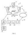
図1は、実施形態による真空システムを示している。この真空システム5内には、監督ノード20によって制御される3つのクライオポンプ10が存在する。監督ノード20は、真空ポンプの故障を予測するための診断モデルを含む論理部を含有する22として示す診断回路を含む。
FIG. 1 shows a vacuum system according to an embodiment. Within this vacuum system 5 there are three
作動中に、真空ポンプ10に関連付けられたセンサ(図示せず)は、ポンプの作動条件を感知し、これらの作動条件を示す信号を監督ノード20に送る。監督ノード20内の診断回路22は、信号の少なくとも一部をサンプリングし、サンプリング信号を入力データとして診断モデルに入力する。これらの作動条件は、真空ポンプの第1の段の温度、真空ポンプの第2の段の温度、真空ポンプ段の各々において望ましい温度に到達するのに要した時間、真空ポンプモータの速度、及び真空ポンプ10の作動を具体的に示す他の変数を含むことができる。
During operation, sensors (not shown) associated with
一部の実施形態では、真空ポンプは、冷凍機の第1の段に両方共に結合された第1の段アレイ及び放射線シールドと冷凍機の第2の段に結合された第2の段アレイとを有する2段クライオポンプである。そのようなクライオポンプは、第1の段アレイ及び第2の段アレイに関して、これらの温度をモニタするための温度センサを有する。クライオポンプの再生中に、クライオポンプは、凝縮ガスが解放されるように加熱される。この手順中にこれらのアレイを加熱するための電気加熱器回路を含むことができる加熱器が存在する。診断システムへの入力は、これらのアレイに関する温度センサの温度読取値と、加熱器回路に供給される電流のような加熱器への入力と、モータの速度とを含むことができる。 In some embodiments, the vacuum pump comprises a first stage array both coupled to the first stage of the refrigerator and a second stage array coupled to the radiation shield and the second stage of the refrigerator. is a two-stage cryopump with Such cryopumps have temperature sensors for the first stage array and the second stage array for monitoring their temperatures. During regeneration of the cryopump, the cryopump is heated such that condensed gases are released. A heater is present that can include an electrical heater circuit for heating these arrays during this procedure. Inputs to the diagnostic system can include temperature sensor temperature readings for these arrays, inputs to the heater such as current supplied to the heater circuit, and motor speed.
これらの信号の少なくとも一部は、これらの信号の変化及び値からポンプの各々に関する故障確率を予測する診断モデルに入力される。この点に関して、この実施形態では、診断モデルは、予め決められた期間内でポンプのうちの1つの故障確率をいつ予測するかを決定する。この予め決められた期間は、例えば、45日とすることができ、この期間は、予定保守間の時間とすることができる。これに代えて、予め決められた期間は、モデルに依存して予定保守間の時間よりも短くすることができる。確率が予め決められた値、この例では50%よりも大きくなく、予め決められた時間長、この場合は6日間にわたってこの値を上回ったままに留まる場合に、一般的には次の予定保守において対応するポンプを交換しなければならないことを示す警告信号が生成される。閾値及び設定時間は予め決定されず、ポンプの使用パターン及び故障パターンに基づいて変更及び最適化することができることに注意しなければならない。 At least some of these signals are input into a diagnostic model that predicts the failure probability for each of the pumps from the changes and values of these signals. In this regard, in this embodiment, the diagnostic model determines when to predict the probability of failure of one of the pumps within a predetermined period of time. This predetermined period of time may be, for example, 45 days, and this period of time may be the time between scheduled maintenance. Alternatively, the predetermined period can be shorter than the time between scheduled maintenance depending on the model. If the probability is not greater than a predetermined value, in this example 50%, and remains above this value for a predetermined length of time, in this case 6 days, then generally the next scheduled maintenance A warning signal is generated indicating that the corresponding pump must be replaced at . It should be noted that the thresholds and set times are not predetermined and can be changed and optimized based on pump usage and failure patterns.
故障予測に対する期間が例えば30日間であり、保守期間がこの期間よりも長く、例えば、45日間であり、この信号が作動期間の終了に向けてトリガされる場合に、この警告信号は、ポンプを交換しなければならないが、次の保守期間まではそうしなくてよいことを示すことができる。 If the period for failure prediction is e.g. 30 days and the maintenance period is longer than this period e.g. It can indicate that it must be replaced, but not until the next maintenance period.
ポンプの交換に続いて、一部の実施形態では、修理技術者は、交換されたポンプの健全性を検査し、このポンプの条件及び時に実際の故障の前の予測寿命を示す情報を監督ノード20に入力することになる。この点に関して、このポンプは、過度に早く交換されていた場合があり、この情報は、モデルを最適化する時に有利である場合がある。導出することができる場合にポンプの故障の原因に関する情報を入力することができる。 Following pump replacement, in some embodiments, a repair technician inspects the health of the replaced pump and reports information indicative of the pump's condition and sometimes expected life before actual failure to a supervisory node. 20 will be entered. In this regard, the pump may have been replaced too early, and this information may be beneficial when optimizing the model. Information about the cause of pump failure can be entered if it can be derived.
従って、監督ノード20内で診断モデル22を使用することにより、将来のいずれかの予め決められた時点でのポンプの故障の正確な予測を決定することができ、次に、ポンプを至急交換することができるように全体の真空システムを停止することを必要とするのではなく、ポンプを予定保守中に交換することができる。
Therefore, by using the
この実施形態では、リモートシステム又はクラウドベースのシステム30への接続も存在する。リモートシステム30内には、データをデータストレージ34又は診断モデル33に送るストリーミングデータ管理ツール32が存在し、診断モデル33は、ログパーサー33aと、データストレージ33bと、機械学習エンジン35とを含む。リモートシステム30内では、いくつかのデータ演算が発生し、これらは、システム内の各ポンプに関するストリーミングデータの管理及び解析、データレイク34のような構造での長期格納、故障確率を迅速に出力するための非常に専有的な機械学習アルゴリズム35による処理を含むがこれらに限定されない。これらの出力は、ホスト25(例えば、ツール制御システム及び/又は工場処理データ管理システム)、修理技術者、又はエンドユーザに様々な形態及びモバイルデバイスを含む様々なプラットフォームで送ることができる。
In this embodiment there is also a connection to a remote or cloud-based
上述の演算は、それらがクラウド内で実施される多くの実施形態ではローカルサーバ上で実施することができるが、クラウドは、機械学習モデル及び/又はソフトウエアを必要に応じて多くの場合に更新する機能に関して際立った利点をもたらし、同時に、作動するためのフレームである拡張可能で廉価な標準アーキテクチャ(例えば、Amazon Web Services、IBM Watson、又は均等物)を提供する。 Although the operations described above can be performed on local servers in many embodiments where they are performed in the cloud, the cloud often updates machine learning models and/or software as needed. It offers distinct advantages in terms of the ability to perform, while at the same time providing a scalable and inexpensive standard architecture (eg Amazon Web Services, IBM Watson, or equivalent) that is the frame on which to operate.
リモートシステム又はクラウドベースのシステムは、同じタイプの多くのポンプの作動からのデータをデータベース又はデータレイク34に格納するように構成される。これらのデータは、温度、モータ速度、加熱器入力、再生パラメータ、使用年数等であるがこれらに限定されない。リモートシステム又はクラウドベースのシステム30は、これらのデータを用いて診断モデルを生成及び更新するための論理部33を含む。クラウドベースの論理部33は、同じタイプの複数のポンプの作動条件を示すデータを含むデータレイク34にこれらのポンプが再生され、修理され、交換される時点を含む予め決められた時間中にアクセスする。
A remote system or cloud-based system is configured to store data from the operation of many pumps of the same type in a database or
論理部33は、これらのデータから診断モデルを生成することができる。診断モデルを生成するのに、論理部33は、データレイク34をサンプリングし、それを収集されたポンプの作動条件を示すデータに基づいて複数のポンプの故障確率を予測する機械学習アルゴリズム35に入力する。論理部33は、データを受信するためのログパーサー33aと、データストア33bと、機械学習エンジン35とを含む。この予測は、ポンプの格納された実際の故障率と比較され、確率及び故障率が望ましい程度に一致するまでモデルのパラメータが変えられる。この時点で、モデルは十分に正確であると考えられ、監督ノード20内の診断回路22での使用に向けて送られる。
作動中に、監督ノード20は、ポンプに関連付けられたセンサからのその作動条件、並びに再生及び故障を検出する収集データを交換された時のポンプの条件に関して修理技術者が入力した情報と共に定期的に送信することができ、これらのデータをデータレイク34に追加することができる。この処理は、ストリーミングデータ管理回路32によって制御される。これに代えて及び/又はこれに加えて、データは、モデルの精度が予め決められた程度を下回ったことを修理技術者が気付くのに応答して手動又はストリーミング管理回路32のいずれかによってアップロードすることができる。
During operation, the
リモート論理部33は、要求に基づいて追加データを用いて機械学習アルゴリズム35を再度作動させて更新された改善されたモデルを生成し、それを監督ノード20に定期的にアップロードしてそれまで格納されていたモデルを置換することができる。このようにして、モデルは、絶えず改善され、更新された条件に適応することになる。
The
一部の実施形態では新しい収集データはデータレイク34に単純に追加されるが、他の実施形態ではデータのうちの一部に置き換わることができる。置換されたデータは、最も古いデータとして選択することができ、及び/又はそれは、対応する型のポンプの特徴を最も示さないものとして選択することができる。
While in some embodiments the new collected data is simply added to the
これに代えて及び/又はこれに加えて、論理部33は、データを学習アルゴリズム35に入力する前にフィルタリングすることができ、この処理中に受信データ内のいずれの異常値も除去することができる。この点に関して、ポンプの作動条件は、再生の直前又は直後のようなある一定の時点ではポンプの通常作動の特徴を示さない場合があり、従って、そのようなデータは、機械学習アルゴリズム35に追加されるデータからフィルタ除去することができる。
Alternatively and/or in addition,
図2は、様々なポンプから収集されたデータから診断モデル又は予測モデル155がどのように形成されるかを示している。モデルを構成するために機械学習アルゴリズムの中に入力されるデータは、特定のポンプに関するデータであり、かつポンプの製造番号、ポンプの部品番号、ポンプのモデル、ポンプが取り出されて交換された/取り外されたか否か、ポンプが設置されて稼働した日付/時間、直近のポンプデータが記録された日付/時間、ポンプに関する持続時間、設置時のポンプの初期時間、ポンプが設置された工場、ポンプが設置されたツールの名称、ツールの製造業者、ツールのタイプ及びツールステーション名、ポンプが修理調整されたとして印されているか否かを含むことができる初期ポンプデータ100を含む。
FIG. 2 shows how a diagnostic or
これに加えて、ポンプの作動を示す初期ポンプログ110が機械学習アルゴリズムの中に入力され、この初期ポンプログ110は、直近の10日間、30日間、60日間の第1の段の温度の加重平均、直近の10日間、30日間、60日間の第2の段の温度の加重平均、直近の10日間、30日間、60日間のRPMの加重平均、第1の段の温度の最高値、第2の段の温度の最高値、RPMの最高値を含むことができる。
In addition, an initial pump log 110 indicative of pump operation is input into the machine learning algorithm, and this
初期ポンプ製造検査120も入力することができ、この製造検査120は、ポンプの合格/不合格計数値及び合格の集計統計値を含むことができる。再生データ130も入力することができ、この再生データ130は、ポンプの再生段階、第1の段の温度、第2の段の温度、モータステータス、パージバルブステータス、ラフバルブステータス、加熱器1ステータス、加熱器2ステータス、加熱器1パーセントオン、加熱器2パーセントオン、モータRPM、ポンプの持続時間、最後の高速再生からの時間、最後の完全再生からの時間、実時間記録の日付、再生するのに要した時間、再生が開始したポンプ時間、再生が開始した日付/時間、再生が終了した日付/時間、再生の終了時の第1の段の温度、再生の終了時の第2の段の温度、再生に対するベース圧力設定、再生に対する増大率限界設定、実施された増大率サイクル回数、ポンプが荒仕上げ条件になるのに要した時間、ポンプが冷却するのに要した時間、直近の完全再生とポンプが再生し始めた時点の間の時間、直近の10日間、30日間、60日間の第1の段の温度の加重平均、直近の10日間、30日間、60日間の第2の段の温度の加重平均、直近の10日間、30日間、60日間のRPMの加重平均、第1の段の温度の最高値、第2の段の温度の最高値、RPMの最大値を含むことができる。これらの再生データは、欠損データに関して検査され、一部の場合は集計再生データ131を生成するための標準再生値にすることができる。
An initial
機械学習技術を用いて最初の診断モデルを構成するための処理の開始時に、上記で概説したようなポンプデータは、いくつかの異なる情報ソースから収集される。これらのデータは、ポンプに関連付けられたセンサから収集された作動時ポンプデータを含み、更に300時間よりも長く作動したポンプに関するデータを含む。製造時にポンプに対して行われた検査からのデータ及びポンプの再生中に収集されたデータと同様に、データが経時的にどのように変化するかを示すポンプログも収集される。次に、これらのデータは、不要な属性、異常値、及びデータが適切ではない又は必要とされないと見なされる条件、又は一般的にポンプの作動の特徴を示すものではないと考えられる条件を除去するようにフィルタリングされ、フィルタリングされたデータから集計ポンプデータ101、集計ポンプログ111、集計製造検査121、及び集計再生データ131が与えられる。
At the outset of the process of constructing an initial diagnostic model using machine learning techniques, pump data as outlined above is collected from several different sources of information. These data include operational pump data collected from sensors associated with the pump, and data for pumps that have been on for more than 300 hours. A pump log is also collected that shows how the data changes over time, as well as data from tests performed on the pump during manufacture and data collected during pump regeneration. These data are then filtered out of unnecessary attributes, outliers, and conditions under which the data are not considered appropriate or needed, or generally uncharacteristic of the operation of the pump. The filtered data provides
次に、これらのデータは、未交換ポンプに関する直近2ヶ月間のデータ及び直前(前2時間)及び再生直後(後4時間)のデータを除去するように処理される。 These data are then processed to remove data for the most recent two months and just before (2 hours before) and just after regeneration (4 hours after) for unchanged pumps.
次に、収集データは、この例では300個の交換されたポンプ及び100個の未交換ポンプからのデータを含むトレーニングデータ140と、39個の交換されたポンプ及び9個の未交換ポンプからのデータを含む予測データ150とに分割される。これらのデータは、予測モデル155の生成に使用される。
The collected data is then training
トレーニングデータ140は、特徴の生成では機械学習アルゴリズムを定めるのに及びモデルを用いてデータをトレーニングするのに使用される。予測データ150は、機械学習アルゴリズムを適用するのに使用される。
これらの処理から予測モデル155が生成される。
A
要約すると、収集トレーニングデータ140は、機械学習アルゴリズムの中に入力され、かつセンサから収集されたデータからポンプの故障を予測するための診断モデルを生成するためのトレーニングデータとして使用される。トレーニングデータ140から生成された値と実際のデータとを比較することによってモデルが構成され、これら2つが整合していると見なされた時に、このモデルは、真空システムでの使用に向けて出力される。
In summary, the collected
使用することができる多くの異なるタイプの機械学習アルゴリズムが存在する。実際に、トレーニングデータ140は、いくつかの異なるモデルに入力することができ、最も正確な予測を有する診断モデルを与えるものが選択される。この点に関して、この処理は反復処理であり、モデルの精度は、予測故障率とデータの実際の故障率とを比較することによって決定することができる。上述のように、ポンプの予測された故障は、ポンプが何らかの修理を必要とする故障であり、従って、実際の「故障」は、ポンプの作動が所要限界の範囲外にある実際の「状況」に関連する場合があり、又はそれは、単純にポンプが機能することができるように交換する時点である場合がある。
There are many different types of machine learning algorithms that can be used. In practice, the
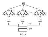
図3は、上述のデータと併用された場合に特に良好な結果が得られる診断モデルを生成することが見出された1つの機械学習アルゴリズムの例を示している。このアルゴリズムは、この場合は数百本のツリーを有する複数のフォレストが使用され、各ツリーが予測を行い、各フォレストが確率を見つけるランダムフォレスト簡略化機械学習アルゴリズムである。次に、複数のフォレストからの最低故障確率が決定され、この最低故障確率は、確率が0.5に達した又はそれを超えた時にトリガされるように選択される警告を生成するのに使用される。そのような確率が6日間連続して続いた場合に、次の予防保守時点での交換が勧められる。 FIG. 3 shows an example of one machine learning algorithm that has been found to produce diagnostic models that perform particularly well when used in conjunction with the data described above. This algorithm is a random forest simplified machine learning algorithm in which multiple forests, in this case hundreds of trees, are used, each tree making predictions and each forest finding probabilities. The lowest probability of failure from multiple forests is then determined and this lowest probability of failure is used to generate an alert that is selected to be triggered when the probability reaches or exceeds 0.5. be done. If such probability persists for 6 consecutive days, replacement at the next preventive maintenance time is recommended.
従って、インスタンス200から始まり、ランダムフォレスト技術を用いてツリー1 201、ツリー2 202、...、ツリーn 20nに到達する。これらのツリーから、異なるクラス205a、205b、205nが導出され、多数決209によって最終クラス210に到達する。
Thus, starting from
図4は、実施形態の診断モデルを生成又は更新する方法での段階を示す流れ図を示している。最初に、段階S10では、複数のポンプの作動条件を示すデータが機械学習アルゴリズムに入力される。これらのデータは、図1のデータレイク34のようなデータベースからのデータとすることができる。段階S20では、機械学習アルゴリズムからポンプの各々の故障確率が導出され、段階S30においてこれらのポンプに関する再生データ及び/又は修理データを含む実際の故障と比較される。この点に関して、ポンプは、予測通りに故障しない可能性があるが、故障することを回避するために修理又は再生される場合があり、従って、これらのデータが使用される。次に、予測確率の精度が決定される。
FIG. 4 shows a flow diagram showing steps in a method of generating or updating a diagnostic model of an embodiment. Initially, at step S10, data indicative of operating conditions for a plurality of pumps are input to a machine learning algorithm. These data may be data from a database such as
次に、段階S40では、重み係数を含むことができるパラメータ及び/又はモデルの実際のアルゴリズムが変更され、段階S50で更新された故障確率が決定される。次に、生成された確率と実際の故障を比較することにより、更新された確率の精度が決定され、D5でこの確率がそれまでの尺度よりも正確であると決定された場合(「イエス」)には、S40でパラメータは同じ方向に変更され、再計算が実施される。更新された尺度の精度の方が低かった場合に(D5での「ノー」)、段階S70でそれまでの値を用いて診断モデルが生成される。このフローは、複雑な手順の極度に単純化した概略のものであり、理解されるように、パラメータを変化させる段階は、各々がパラメータ及び/又は実施される計算の部分集合を含むいくつかの段階で行うことができ、及び/又はこれらの変動は、最初に大まかな段階で行い、大まかな段階から最小値が見つかった時に、次に、細かな段階で行うことができる。いずれの場合にも、本方法は反復的であり、改善がもはや感じられない時又は望ましい精度に達した時に、これらのパラメータから診断モデルを生成することができる。 Next, in step S40, the parameters, which may include weighting factors, and/or the actual algorithm of the model are changed, and the updated failure probabilities are determined in step S50. The accuracy of the updated probabilities is then determined by comparing the generated probabilities with the actual failures, and if D5 determines that this probability is more accurate than the previous measure ("yes" ), in S40 the parameters are changed in the same direction and a recalculation is performed. If the updated scale is less accurate ("no" at D5), the previous values are used to generate a diagnostic model in step S70. This flow is an overly simplistic outline of a complex procedure, and as will be appreciated, the steps of varying the parameters are divided into several steps, each containing a subset of the parameters and/or calculations performed. It can be done in steps and/or these variations can be done in coarse steps first and then in fine steps when a minimum is found from the coarse steps. In either case, the method is iterative and a diagnostic model can be generated from these parameters when improvement is no longer felt or desired accuracy is reached.
図5は、実施形態によるポンプの故障を予測する方法を示す流れ図である。本方法は、段階S100でポンプの作動条件を示す信号をポンプに関連付けられたセンサからサンプリングする段階を含む。段階S110で信号が診断モデルに入力され、段階S120でこのモデルからポンプ故障確率が決定され、D15でこの確率が予め決められた値を上回っており、かつ実際にこの値を予め決められた時間にわたって上回ったままに留まっているか否かが決定され、そうである場合に(「イエス」)、段階S130でポンプを修理しなければならない又は交換しなければならないことを示す警告が出力される。確率が閾値を上回っていない場合に、警告は出力されない。 FIG. 5 is a flow diagram illustrating a method of predicting pump failure according to an embodiment. The method includes sampling a signal indicative of the operating condition of the pump from a sensor associated with the pump at step S100. At step S110 the signal is input to the diagnostic model, from this model at step S120 the pump failure probability is determined, at D15 if this probability exceeds a predetermined value and if in fact this value is exceeded for a predetermined time. It is determined whether it has remained above the limit for over a period of time, and if so ("yes"), a warning is output in step S130 indicating that the pump must be repaired or replaced. No warning is output if the probability is not above the threshold.
図6は、単一ポンプの例に対するこの手法の値を示している。いくつかのモニタ値の変動、すなわち、ポンプの第1の段の温度であるT1、ポンプの第2の段の温度であるT2、ポンプモータ300の速度、再生サイクルの終了時のT1の値T1end及び再生サイクルの終了時のT2の値T2end、所要温度まで冷却するための時間310の変動が示されており、これらの値から、実施形態の診断モデルを用いて故障確率330が検出される。この確率は、その動向を追ってモニタすることができ、予め決められた閾値を超えた時に、ポンプを交換するための警告/警報を生成することができる。
FIG. 6 shows the value of this approach for a single pump example. Variations in several monitored values: T1, the temperature of the first stage of the pump; T2, the temperature of the second stage of the pump; the speed of the
図6Aでは、赤色区域の始まりは、ポンプが故障する可能性があることが予測され、交換すべき場所を示しており、この場合は、ポンプは交換されず、図6Aは、これらの値がその後にどのように変化するかを示している。図6Bは、ポンプが故障する可能性がある時点でポンプが交換される別の実施形態を示している。 In FIG. 6A, the beginning of the red area indicates where the pump is expected to fail and should be replaced, in which case the pump is not replaced, and FIG. It shows how it will change. FIG. 6B shows another embodiment in which the pump is replaced when it may fail.
実施形態は、経時的にポンプ性能をモニタし、ポンプに修理を提供する従来の修理提供と連携して使用することができる。従来の修理提供では、データがポンプから収集される。これらのデータは、温度、モータ速度、ビータ入力、再生パラメータ、使用年数などを含むことができるがこれらに限定されない。これらのデータは、埋め込みシステムによって収集されて解釈される。データ要約がパッケージ化され、予め決められた期間毎に電子メールで送信される。データは、未処理形態で閲覧するか又はグラフのセットとして視覚的に閲覧するかのいずれかを行うことができる。修理技術者は、後者を用いてT1、T2、及びrpmを単位とするポンプ速度のような主な制御パラメータの傾向を識別する。次に、修理技術者は、この情報をこの機器の予備知識と組み合わせて、それを用いてエンドユーザのポンプ群をポンプの交換又は他の補正措置を提案することに関して管理する。言い換えれば、そのようなシステムは、ポンプ性能への洞察を与えるが、傾向及びパターンを認識することができる経験豊かな修理技術者による能動的な関与を必要とする。 Embodiments can be used in conjunction with traditional repair offerings that monitor pump performance over time and provide repairs to pumps. In a traditional repair offer, data is collected from the pump. These data can include, but are not limited to, temperature, motor speed, beater input, regeneration parameters, age, and the like. These data are collected and interpreted by the embedded system. Data summaries are packaged and emailed at predetermined intervals. The data can be viewed either in raw form or visually as a set of graphs. Repair technicians use the latter to identify trends in key control parameters such as T1, T2, and pump speed in rpm. The repair technician then combines this information with prior knowledge of the equipment and uses it to manage the end user's pump fleet with respect to suggesting pump replacement or other corrective action. In other words, such systems provide insight into pump performance, but require active involvement by an experienced repair technician who can recognize trends and patterns.
本提案のソリューションは、同じ基本データに基づいて構成されるが、特定のポンプがいずれかの固定間隔(例えば、30日間、45日間、60日間)で故障する可能性を算定するために最先端の非常に専有的な機械学習アルゴリズムを使用する。これらのアルゴリズムは、1又は2以上の機械学習(ML)方法(ランダムフォレスト、ニューラルネットワーク、主成分分析などを含むがこれらに限定されない)を利用する。MLアルゴリズムは、過去の交換事象が明確に識別されたこのデータベースに対して構築及び「トレーニング」され、次に、データベースの別の部分集合に対して検証される。 The proposed solution builds on the same underlying data, but is state-of-the-art to calculate the probability that a particular pump will fail at any fixed interval (e.g., 30 days, 45 days, 60 days). using our highly proprietary machine learning algorithms. These algorithms utilize one or more machine learning (ML) methods (including but not limited to random forests, neural networks, principal component analysis, etc.). The ML algorithm is built and "trained" against this database in which past exchange events are clearly identified, and then validated against another subset of the database.
この手法の主な利点は、以下を含む:
・予測がポンプ作動の他の局面を表す「特徴」又は変換変数に依存するので、T1、T2、及びポンプ速度のような通常のインジケータに予測が反映されると考えられる時点のはるか前に性能劣化を予測するポンプの性能劣化を予測する機能。
・エンドユーザによるポンプの時期尚早の交換に至る可能性があるT1及びT2に対する厳しい制御限界への(多くの場合に間違った)依存を回避する又は少なくとも低減すること。
・モデル予測の精度及び/又はリードタイムを改善することができる追加のセンサ又は診断情報を組み込むためのプラットフォームを生成すること。
・確率関数を用いてポンプを先見的に交換することに関する指針を与え、エンドユーザが指針に従う場合に予定外のダウンタイムの排除(原理的に)又は少なくとも低減を可能にすることができること。
The main advantages of this technique include:
Performance well before the point in time when predictions are thought to be reflected in typical indicators such as T1, T2, and pump speed, as predictions depend on "features" or transformation variables that represent other aspects of pump operation A function that predicts performance deterioration of a pump that predicts deterioration.
• Avoiding or at least reducing the (often incorrect) reliance on tight control limits on T1 and T2 that can lead to premature replacement of the pump by the end user.
- Creating a platform for incorporating additional sensor or diagnostic information that can improve model prediction accuracy and/or lead time.
- A probability function can be used to provide guidance on proactively replacing pumps, allowing the elimination (in principle) or at least reduction of unscheduled downtime if the end-user follows the guidance.
本明細書で添付図面を参照して本発明の例示的実施形態を詳細に開示したが、本発明は、厳密な実施形態に限定されないこと、及び当業者は特許請求の範囲及びその均等物によって定められる本発明の範囲から逸脱することなくこれらの実施形態に様々な変形及び修正を加えることができることは理解される。 Although illustrative embodiments of the invention have been disclosed in detail herein with reference to the accompanying drawings, it is understood that the invention is not limited to the precise embodiments and that those skilled in the art will appreciate by the claims and equivalents thereof. It is understood that various variations and modifications can be made to these embodiments without departing from the scope of the invention as defined.
参照符号
5 真空システム
10 クライオポンプ
20 監督ノード
22 診断回路
25 ホスト
30 リモート又はクラウドベースのシステム
32 データストリーミング管理回路
33 診断モデル生成論理部
33a ログパーサー
33b データストレージ
34 データレイク
35 機械学習アルゴリズム
Reference numeral 5
Claims (19)
前記少なくとも1つのクライオポンプに関連付けられた複数のセンサであって、前記複数のセンサの各々が前記少なくとも1つのクライオポンプの作動条件を感知するように構成された、
前記複数のセンサの少なくとも一部からサンプリングされた信号を受信するように構成された診断回路であって、前記診断回路が、前記クライオポンプの診断モデルを含み、前記診断モデルが、複数の再生及び修理期間にわたって作動する同じタイプの複数のクライオポンプの履歴データから導出され、かつ、前記少なくとも一部のセンサから前記サンプリングされた信号の値を予め決められた時間内の前記ポンプの故障の確率に関連付けるように構成され、前記診断回路が、前記サンプリングされた信号を前記診断モデルに適用し、かつ前記モデルの出力から前記予め決められた時間内の前記少なくとも1つのクライオポンプの故障の前記確率を決定するように構成された診断回路と、
を含むことを特徴とする真空システム。 at least one cryopump;
a plurality of sensors associated with the at least one cryopump, each of the plurality of sensors configured to sense an operating condition of the at least one cryopump;
diagnostic circuitry configured to receive signals sampled from at least a portion of the plurality of sensors, the diagnostic circuitry including a diagnostic model of the cryopump, the diagnostic model including a plurality of regenerations and derived from historical data of a plurality of cryopumps of the same type operating over a period of repair, and combining the values of the sampled signals from the at least some sensors with the probability of failure of the pump within a predetermined time period; configured to correlate, the diagnostic circuitry applying the sampled signals to the diagnostic model and determining the probability of failure of the at least one cryopump within the predetermined time period from the output of the model; a diagnostic circuit configured to determine
A vacuum system comprising:
前記診断回路は、前記複数のクライオポンプの各々から信号を受信し、かつ前記クライオポンプ故障のうちの各々の確率を決定するように構成される、
ことを特徴とする請求項1から請求項2のいずれかに記載の真空システム。 a vacuum system including a plurality of cryopumps;
the diagnostic circuitry configured to receive a signal from each of the plurality of cryopumps and determine a probability of each of the cryopump failures;
3. The vacuum system according to any one of claims 1 to 2, characterized in that:
前記交換されたポンプの前記条件を示す前記データを前記定期的に出力されるデータの一部として出力するように構成される、
ことを特徴とする請求項6に記載の真空システム。 an input for receiving data from a repair technician indicating the condition of the pump replaced during said maintenance period;
configured to output the data indicating the condition of the replaced pump as part of the periodically output data;
7. A vacuum system according to claim 6, characterized in that:
前記少なくとも1つのクライオポンプの作動条件を示す複数の信号を前記クライオポンプに関連付けられたセンサからサンプリングする段階と、
前記信号の少なくとも一部を前記クライオポンプの診断モデルに入力する段階であって、前記診断モデルが、前記ポンプの再生、修理、及び故障のうちの少なくとも1つをその少なくとも一部が含む複数の期間にわたって作動する同じタイプの複数のクライオポンプの履歴データから導出され、前記診断モデルが、信号を前記ポンプ故障の確率に関連付ける前記入力する段階と、
前記モデルの出力から前記少なくとも1つのクライオポンプの故障の確率を決定する段階と、
を含むことを特徴とする方法。 A method of monitoring a vacuum system including at least one cryopump, comprising:
sampling a plurality of signals indicative of operating conditions of the at least one cryopump from sensors associated with the cryopump;
inputting at least a portion of the signal into a diagnostic model of the cryopump, the diagnostic model comprising a plurality of diagnostic models, at least a portion of which include at least one of regeneration, repair, and failure of the pump; said inputting step, wherein said diagnostic model is derived from historical data of a plurality of cryopumps of the same type operated over a period of time and relates signals to probabilities of said pump failure;
determining a probability of failure of the at least one cryopump from the output of the model;
A method comprising:
を含むことを特徴とするコンピュータプログラム。 machine readable instructions operable when executed by a computer to control the computer to perform the method of claim 10;
A computer program comprising:
再生、修理、及び故障のうちの少なくとも1つをその少なくとも一部が含む複数の期間にわたったサンプリングされた前記複数のクライオポンプの前記感知された作動条件を格納するデータベースから、前記タイプの複数のクライオポンプの作動条件を感知することから収集されたデータを機械学習アルゴリズムの中に入力し、ある一定の時間内の前記ポンプ故障の複数の確率を生成する段階と、
それぞれのポンプに対する前記確率を前記データベースから取り出された前記ポンプに対するポンプ故障タイミングと比較し、かつ決定された前記確率と前記ポンプ故障タイミングの差を縮小するように前記機械学習アルゴリズム内のパラメータを更新する段階と、
前記差が最小値又は予め決められた値のうちの一方に達するまで前記段階を繰り返す段階と、
前記アルゴリズム及び前記差を与えたパラメータから前記診断モデルを生成する段階と、
を含むことを特徴とする方法。 A method of generating a diagnostic model for a type of cryopump comprising:
from a database storing the sensed operating conditions of the plurality of cryopumps sampled over a plurality of time periods, at least some of which include at least one of regeneration, repair, and failure; inputting data collected from sensing operating conditions of a cryopump into a machine learning algorithm to generate a plurality of probabilities of said pump failure over time;
comparing the probabilities for each pump with pump failure timings for the pumps retrieved from the database and updating parameters within the machine learning algorithm to reduce the difference between the determined probabilities and the pump failure timings; and
repeating the steps until the difference reaches one of a minimum value or a predetermined value;
generating the diagnostic model from the algorithm and the differencing parameters;
A method comprising:
同じタイプの複数のクライオポンプの作動条件を示す複数の信号を受信する段階と、
前記複数のクライオポンプに対するポンプ保守及び故障タイミングを受信する段階と、
前記受信データを前記データベースに追加し、かつ前記更新されたデータベースからのデータを用いて更新された診断モデルを生成するために請求項12から請求項14のいずれか1項の前記方法を実施する段階と、
前記更新された診断モデルを出力する段階と、
を含むことを特徴とする方法。 A method for updating the diagnostic model generated according to any one of claims 12 to 14, comprising:
receiving a plurality of signals indicative of operating conditions for a plurality of cryopumps of the same type;
receiving pump maintenance and failure timing for the plurality of cryopumps;
performing the method of any one of claims 12 to 14 to add the received data to the database and to generate an updated diagnostic model using data from the updated database. stages and
outputting the updated diagnostic model;
A method comprising:
前記データは、前記診断モデルの前記更新中に前記機械学習アルゴリズムに入力される、
ことを特徴とする請求項15に記載の方法。 further comprising receiving data indicative of the condition of the replaced pump following the diagnostic model indicating that the pump is likely to fail within a predetermined time;
the data is input to the machine learning algorithm during the update of the diagnostic model;
16. The method of claim 15, wherein:
を含むことを特徴とするコンピュータプログラム。 machine-readable instructions operable when executed by a computer to control said computer to perform a method according to any one of claims 12 to 16;
A computer program comprising:
を含むことを特徴とするリモート診断モジュール。 a computer configured to execute the computer program according to claim 17;
A remote diagnostic module comprising:
前記リモート診断モジュールは、前記真空システムによって出力された信号を受信し、前記受信信号を用いてクライオポンプ作動の前記データベースを更新し、かつ前記更新されたデータベースからのデータを前記機械学習アルゴリズムに入力することによって更新された診断モデルを生成するように構成される、
ことを特徴とするシステム。 19. A system comprising the vacuum system of any one of claims 5-7 or 9 and the remote diagnostic module of claim 18, comprising:
The remote diagnostic module receives signals output by the vacuum system, uses the received signals to update the database of cryopump operations, and inputs data from the updated database into the machine learning algorithm. configured to generate an updated diagnostic model by
A system characterized by:
Applications Claiming Priority (3)
| Application Number | Priority Date | Filing Date | Title |
|---|---|---|---|
| GB1909762.5 | 2019-07-08 | ||
| GBGB1909762.5A GB201909762D0 (en) | 2019-07-08 | 2019-07-08 | Vacuum system with diagnostic circuitry and a method and computer program for monitoring the health of such a vacuum system |
| PCT/IB2020/056366 WO2021005502A1 (en) | 2019-07-08 | 2020-07-07 | Vacuum system with diagnostic circuitry and a method and computer program for monitoring the health of such a vacuum system |
Publications (2)
| Publication Number | Publication Date |
|---|---|
| JP2022540407A true JP2022540407A (en) | 2022-09-15 |
| JP7689943B2 JP7689943B2 (en) | 2025-06-09 |
Family
ID=67623255
Family Applications (1)
| Application Number | Title | Priority Date | Filing Date |
|---|---|---|---|
| JP2022500536A Active JP7689943B2 (en) | 2019-07-08 | 2020-07-07 | Vacuum system having diagnostic circuitry and method and computer program for monitoring the health of such a vacuum system - Patents.com |
Country Status (9)
| Country | Link |
|---|---|
| US (1) | US12282323B2 (en) |
| EP (1) | EP3997535A1 (en) |
| JP (1) | JP7689943B2 (en) |
| KR (1) | KR20220027939A (en) |
| CN (1) | CN114051600A (en) |
| GB (1) | GB201909762D0 (en) |
| IL (1) | IL289605B2 (en) |
| TW (1) | TWI841756B (en) |
| WO (1) | WO2021005502A1 (en) |
Families Citing this family (6)
| Publication number | Priority date | Publication date | Assignee | Title |
|---|---|---|---|---|
| EP4071364B1 (en) * | 2022-06-30 | 2026-02-11 | Pfeiffer Vacuum Technology AG | Communication system comprising a vacuum device and an evaluation device, and method for operating the communication system |
| TW202416630A (en) | 2022-09-22 | 2024-04-16 | 英商愛德華有限公司 | Shell stator for a vacuum pump |
| GB2634187A (en) * | 2022-09-28 | 2025-04-09 | Leybold Gmbh | Method for a vacuum pump system |
| CN116066342B (en) * | 2023-01-09 | 2024-08-23 | 安徽万瑞冷电科技有限公司 | Control device and control method for cryopump |
| KR102724367B1 (en) | 2023-01-27 | 2024-11-01 | 한국에너지기술연구원 | Core-Shell Catalyst with Improved Durability and Manufacturing Method Thereof |
| JP7674411B2 (en) * | 2023-04-11 | 2025-05-09 | エドワーズ株式会社 | Vacuum pump and magnetic bearing control device |
Citations (5)
| Publication number | Priority date | Publication date | Assignee | Title |
|---|---|---|---|---|
| JP2000249057A (en) * | 1999-02-26 | 2000-09-12 | Suzuki Shokan:Kk | Method and device for evaluating cryopump |
| JP2005009337A (en) * | 2003-06-17 | 2005-01-13 | Ebara Corp | Diagnostic system for vacuum pump |
| JP2008274865A (en) * | 2007-04-27 | 2008-11-13 | Sumitomo Heavy Ind Ltd | Cryopump system and maintenance method for cryopump |
| JP2018500709A (en) * | 2014-12-01 | 2018-01-11 | アップテイク テクノロジーズ、インコーポレイテッド | Asset health scores and their use |
| JP2018193933A (en) * | 2017-05-18 | 2018-12-06 | 株式会社荏原製作所 | Information processor, reference data determination device, information processing method, reference data determination method and program |
Family Cites Families (11)
| Publication number | Priority date | Publication date | Assignee | Title |
|---|---|---|---|---|
| US6318093B2 (en) | 1988-09-13 | 2001-11-20 | Helix Technology Corporation | Electronically controlled cryopump |
| JP3408752B2 (en) | 1998-09-22 | 2003-05-19 | 三菱電機株式会社 | Failure prediction maintenance device |
| FR2824936B1 (en) * | 2001-05-16 | 2005-09-02 | Schneider Automation | PREDICTIVE DIAGNOSTIC SYSTEM IN A PROGRAMMABLE AUTOMATE |
| US7016751B2 (en) | 2001-07-13 | 2006-03-21 | Helix Technology Corporation | Vacuum system central control information server |
| EP1836576B1 (en) | 2004-12-17 | 2012-02-01 | Korea Research Institute of Standards and Science | A precision diagnostic method for the failure protection and predictive maintenance of a vacuum pump and a precision diagnostic system therefor |
| JP4686572B2 (en) | 2008-05-14 | 2011-05-25 | 住友重機械工業株式会社 | Cryopump, vacuum exhaust system, and diagnostic method thereof |
| JP5679913B2 (en) | 2011-06-14 | 2015-03-04 | 住友重機械工業株式会社 | Cryopump control device, cryopump system, and cryopump monitoring method |
| JP5963459B2 (en) | 2012-01-31 | 2016-08-03 | 住友重機械工業株式会社 | Cryopump and cryopump repair method |
| AU2013245998B2 (en) * | 2012-04-10 | 2016-07-28 | Lockheed Martin Corporation | Efficient health management, diagnosis and prognosis of a machine |
| JP2016153617A (en) | 2015-02-20 | 2016-08-25 | 住友重機械工業株式会社 | Cryopump system, cryopump control device and cryopump regeneration method |
| GB2536461A (en) * | 2015-03-18 | 2016-09-21 | Edwards Ltd | Pump monitoring apparatus and method |
-
2019
- 2019-07-08 GB GBGB1909762.5A patent/GB201909762D0/en not_active Ceased
-
2020
- 2020-07-07 EP EP20740090.4A patent/EP3997535A1/en active Pending
- 2020-07-07 JP JP2022500536A patent/JP7689943B2/en active Active
- 2020-07-07 CN CN202080049715.XA patent/CN114051600A/en active Pending
- 2020-07-07 US US17/625,231 patent/US12282323B2/en active Active
- 2020-07-07 KR KR1020227000449A patent/KR20220027939A/en active Pending
- 2020-07-07 WO PCT/IB2020/056366 patent/WO2021005502A1/en not_active Ceased
- 2020-07-07 IL IL289605A patent/IL289605B2/en unknown
- 2020-07-08 TW TW109123078A patent/TWI841756B/en active
Patent Citations (5)
| Publication number | Priority date | Publication date | Assignee | Title |
|---|---|---|---|---|
| JP2000249057A (en) * | 1999-02-26 | 2000-09-12 | Suzuki Shokan:Kk | Method and device for evaluating cryopump |
| JP2005009337A (en) * | 2003-06-17 | 2005-01-13 | Ebara Corp | Diagnostic system for vacuum pump |
| JP2008274865A (en) * | 2007-04-27 | 2008-11-13 | Sumitomo Heavy Ind Ltd | Cryopump system and maintenance method for cryopump |
| JP2018500709A (en) * | 2014-12-01 | 2018-01-11 | アップテイク テクノロジーズ、インコーポレイテッド | Asset health scores and their use |
| JP2018193933A (en) * | 2017-05-18 | 2018-12-06 | 株式会社荏原製作所 | Information processor, reference data determination device, information processing method, reference data determination method and program |
Also Published As
| Publication number | Publication date |
|---|---|
| TW202111593A (en) | 2021-03-16 |
| EP3997535A1 (en) | 2022-05-18 |
| GB201909762D0 (en) | 2019-08-21 |
| IL289605A (en) | 2022-03-01 |
| WO2021005502A1 (en) | 2021-01-14 |
| US20220269257A1 (en) | 2022-08-25 |
| KR20220027939A (en) | 2022-03-08 |
| US12282323B2 (en) | 2025-04-22 |
| IL289605B2 (en) | 2026-04-01 |
| IL289605B1 (en) | 2025-12-01 |
| JP7689943B2 (en) | 2025-06-09 |
| TWI841756B (en) | 2024-05-11 |
| CN114051600A (en) | 2022-02-15 |
Similar Documents
| Publication | Publication Date | Title |
|---|---|---|
| JP7689943B2 (en) | Vacuum system having diagnostic circuitry and method and computer program for monitoring the health of such a vacuum system - Patents.com | |
| TWI851071B (en) | Method and system for correcting component failures in ion implant semiconductor manufacturing tool | |
| JP4138267B2 (en) | Semiconductor manufacturing apparatus, vacuum pump life prediction method, and vacuum pump repair timing determination method | |
| KR101518448B1 (en) | Baseline predictive maintenance method for target device and computer program product thereof | |
| US6970804B2 (en) | Automated self-learning diagnostic system | |
| CA2426627C (en) | Method and system for analyzing fault and quantized operational data for automated diagnostics of locomotives | |
| CN117664218B (en) | Calibration method of vacuum freeze dryer | |
| JP2005339558A (en) | Method for creating a unified quality assessment for turbine mechanical systems and the like and providing an automatic fault diagnosis tool | |
| KR20120106934A (en) | Method for predicting a rotation fault in the rotor of a vacuum pump, and associated pumping device | |
| JP2010283000A (en) | Predictive detection method of equipment abnormality in semiconductor manufacturing | |
| CN118826301A (en) | Power grid equipment status monitoring method based on digital twin | |
| KR20190077137A (en) | Automatic analysis method of infrastructure operation data and system thereof | |
| KR20250040175A (en) | A method of providing predictive maintenance service using remote-monitoring of air compressor and a predictive maintenance platform for the method | |
| CN118586722A (en) | A method for fault diagnosis of electromechanical equipment in smart power plants | |
| CN111879522B (en) | Steam turbine operation monitoring and fault distinguishing method and system based on time sequence probability | |
| JP6574533B2 (en) | Risk assessment device, risk assessment system, risk assessment method, and risk assessment program | |
| RU2703874C1 (en) | Method of monitoring and predicting operation of a gas turbine plant using a matrix of defects | |
| CN119577681A (en) | Intelligent management method of industrial equipment data based on big data algorithm | |
| CN117171517A (en) | A dynamic early warning method for data center operation failure risks | |
| KR20240006214A (en) | Lifetime prediction method using tendency diagnosis of machine monitoring data | |
| JP2002503843A (en) | Process and equipment diagnosis method | |
| CN116151312A (en) | Pre-warning method and system for heat turbine units based on Mann-Kendall algorithm and LSTM neural network | |
| JP6482742B1 (en) | Risk assessment device, risk assessment system, risk assessment method, and risk assessment program | |
| CN120123927B (en) | Method, equipment and medium for detecting abnormal operation of air sac pump | |
| TWI838134B (en) | Device diagnosis system, device diagnosis device, semiconductor device manufacturing system, and device diagnosis method |
Legal Events
| Date | Code | Title | Description |
|---|---|---|---|
| A621 | Written request for application examination |
Free format text: JAPANESE INTERMEDIATE CODE: A621 Effective date: 20230517 |
|
| A131 | Notification of reasons for refusal |
Free format text: JAPANESE INTERMEDIATE CODE: A131 Effective date: 20240221 |
|
| A977 | Report on retrieval |
Free format text: JAPANESE INTERMEDIATE CODE: A971007 Effective date: 20240222 |
|
| A601 | Written request for extension of time |
Free format text: JAPANESE INTERMEDIATE CODE: A601 Effective date: 20240521 |
|
| A521 | Request for written amendment filed |
Free format text: JAPANESE INTERMEDIATE CODE: A523 Effective date: 20240820 |
|
| A131 | Notification of reasons for refusal |
Free format text: JAPANESE INTERMEDIATE CODE: A131 Effective date: 20241114 |
|
| A521 | Request for written amendment filed |
Free format text: JAPANESE INTERMEDIATE CODE: A523 Effective date: 20250210 |
|
| TRDD | Decision of grant or rejection written | ||
| A01 | Written decision to grant a patent or to grant a registration (utility model) |
Free format text: JAPANESE INTERMEDIATE CODE: A01 Effective date: 20250428 |
|
| A61 | First payment of annual fees (during grant procedure) |
Free format text: JAPANESE INTERMEDIATE CODE: A61 Effective date: 20250528 |
|
| R150 | Certificate of patent or registration of utility model |
Ref document number: 7689943 Country of ref document: JP Free format text: JAPANESE INTERMEDIATE CODE: R150 |