JP2022506830A - Dressing with a protruding layer that allows cleaning of wound bed macrodeformations - Google Patents
Dressing with a protruding layer that allows cleaning of wound bed macrodeformations Download PDFInfo
- Publication number
- JP2022506830A JP2022506830A JP2021524439A JP2021524439A JP2022506830A JP 2022506830 A JP2022506830 A JP 2022506830A JP 2021524439 A JP2021524439 A JP 2021524439A JP 2021524439 A JP2021524439 A JP 2021524439A JP 2022506830 A JP2022506830 A JP 2022506830A
- Authority
- JP
- Japan
- Prior art keywords
- contact layer
- negative pressure
- dressing
- layer
- tissue site
- Prior art date
- Legal status (The legal status is an assumption and is not a legal conclusion. Google has not performed a legal analysis and makes no representation as to the accuracy of the status listed.)
- Pending
Links
- 238000004140 cleaning Methods 0.000 title description 63
- 238000000034 method Methods 0.000 claims abstract description 40
- 239000012530 fluid Substances 0.000 claims description 65
- 239000006260 foam Substances 0.000 claims description 45
- 238000001804 debridement Methods 0.000 claims description 29
- 239000011148 porous material Substances 0.000 claims description 22
- 230000004044 response Effects 0.000 claims description 7
- 230000000295 complement effect Effects 0.000 claims description 5
- 230000000149 penetrating effect Effects 0.000 claims description 2
- 238000010586 diagram Methods 0.000 abstract description 4
- 210000001519 tissue Anatomy 0.000 description 165
- 206010052428 Wound Diseases 0.000 description 103
- 208000027418 Wounds and injury Diseases 0.000 description 103
- 238000011282 treatment Methods 0.000 description 57
- 239000011159 matrix material Substances 0.000 description 48
- 238000005538 encapsulation Methods 0.000 description 30
- 238000002560 therapeutic procedure Methods 0.000 description 27
- 239000000463 material Substances 0.000 description 26
- 239000000243 solution Substances 0.000 description 25
- 229920000642 polymer Polymers 0.000 description 19
- 238000001802 infusion Methods 0.000 description 17
- 239000012459 cleaning agent Substances 0.000 description 13
- 239000003978 infusion fluid Substances 0.000 description 12
- 230000014759 maintenance of location Effects 0.000 description 12
- 230000001965 increasing effect Effects 0.000 description 10
- 230000008569 process Effects 0.000 description 10
- 230000008602 contraction Effects 0.000 description 9
- 230000006378 damage Effects 0.000 description 9
- 239000004433 Thermoplastic polyurethane Substances 0.000 description 7
- 230000001338 necrotic effect Effects 0.000 description 7
- 230000037361 pathway Effects 0.000 description 7
- 229920002725 thermoplastic elastomer Polymers 0.000 description 7
- 229920002803 thermoplastic polyurethane Polymers 0.000 description 7
- 230000008901 benefit Effects 0.000 description 6
- 210000004027 cell Anatomy 0.000 description 6
- 230000007423 decrease Effects 0.000 description 6
- 238000009826 distribution Methods 0.000 description 6
- 210000000416 exudates and transudate Anatomy 0.000 description 6
- 239000000945 filler Substances 0.000 description 6
- 230000035876 healing Effects 0.000 description 6
- 208000015181 infectious disease Diseases 0.000 description 6
- 230000002829 reductive effect Effects 0.000 description 6
- PEDCQBHIVMGVHV-UHFFFAOYSA-N Glycerine Chemical compound OCC(O)CO PEDCQBHIVMGVHV-UHFFFAOYSA-N 0.000 description 5
- 239000011248 coating agent Substances 0.000 description 5
- 238000000576 coating method Methods 0.000 description 5
- 239000002274 desiccant Substances 0.000 description 5
- 230000000694 effects Effects 0.000 description 5
- 239000004744 fabric Substances 0.000 description 5
- 230000003647 oxidation Effects 0.000 description 5
- 238000007254 oxidation reaction Methods 0.000 description 5
- 239000000126 substance Substances 0.000 description 5
- 230000001225 therapeutic effect Effects 0.000 description 5
- 230000000699 topical effect Effects 0.000 description 5
- 102000016911 Deoxyribonucleases Human genes 0.000 description 4
- 108010053770 Deoxyribonucleases Proteins 0.000 description 4
- VYPSYNLAJGMNEJ-UHFFFAOYSA-N Silicium dioxide Chemical compound O=[Si]=O VYPSYNLAJGMNEJ-UHFFFAOYSA-N 0.000 description 4
- 208000025865 Ulcer Diseases 0.000 description 4
- 238000006065 biodegradation reaction Methods 0.000 description 4
- 230000004663 cell proliferation Effects 0.000 description 4
- 239000001913 cellulose Substances 0.000 description 4
- 229920002678 cellulose Polymers 0.000 description 4
- 230000008859 change Effects 0.000 description 4
- 238000005520 cutting process Methods 0.000 description 4
- 238000004090 dissolution Methods 0.000 description 4
- 238000005553 drilling Methods 0.000 description 4
- 230000002255 enzymatic effect Effects 0.000 description 4
- 208000014674 injury Diseases 0.000 description 4
- 230000002195 synergetic effect Effects 0.000 description 4
- 239000002562 thickening agent Substances 0.000 description 4
- 230000008733 trauma Effects 0.000 description 4
- 231100000397 ulcer Toxicity 0.000 description 4
- 229920000954 Polyglycolide Polymers 0.000 description 3
- 229920001247 Reticulated foam Polymers 0.000 description 3
- 230000009471 action Effects 0.000 description 3
- 239000000853 adhesive Substances 0.000 description 3
- 230000001070 adhesive effect Effects 0.000 description 3
- 230000001580 bacterial effect Effects 0.000 description 3
- 230000009286 beneficial effect Effects 0.000 description 3
- 238000004299 exfoliation Methods 0.000 description 3
- 239000000499 gel Substances 0.000 description 3
- 239000007788 liquid Substances 0.000 description 3
- 238000004519 manufacturing process Methods 0.000 description 3
- 239000004633 polyglycolic acid Substances 0.000 description 3
- 238000007789 sealing Methods 0.000 description 3
- 238000003860 storage Methods 0.000 description 3
- 230000029663 wound healing Effects 0.000 description 3
- 102000008186 Collagen Human genes 0.000 description 2
- 108010035532 Collagen Proteins 0.000 description 2
- 206010063560 Excessive granulation tissue Diseases 0.000 description 2
- 206010017533 Fungal infection Diseases 0.000 description 2
- 208000031888 Mycoses Diseases 0.000 description 2
- 229920002201 Oxidized cellulose Polymers 0.000 description 2
- 229920005830 Polyurethane Foam Polymers 0.000 description 2
- 239000004372 Polyvinyl alcohol Substances 0.000 description 2
- 239000004365 Protease Substances 0.000 description 2
- 229920000297 Rayon Polymers 0.000 description 2
- 229920002472 Starch Polymers 0.000 description 2
- 108010023197 Streptokinase Proteins 0.000 description 2
- 238000005273 aeration Methods 0.000 description 2
- 230000015572 biosynthetic process Effects 0.000 description 2
- OSGAYBCDTDRGGQ-UHFFFAOYSA-L calcium sulfate Chemical compound [Ca+2].[O-]S([O-])(=O)=O OSGAYBCDTDRGGQ-UHFFFAOYSA-L 0.000 description 2
- 238000001311 chemical methods and process Methods 0.000 description 2
- 229920001436 collagen Polymers 0.000 description 2
- 239000000356 contaminant Substances 0.000 description 2
- 230000008878 coupling Effects 0.000 description 2
- 238000010168 coupling process Methods 0.000 description 2
- 238000005859 coupling reaction Methods 0.000 description 2
- 230000006837 decompression Effects 0.000 description 2
- 230000007547 defect Effects 0.000 description 2
- 239000003599 detergent Substances 0.000 description 2
- WFPZPJSADLPSON-UHFFFAOYSA-N dinitrogen tetraoxide Chemical compound [O-][N+](=O)[N+]([O-])=O WFPZPJSADLPSON-UHFFFAOYSA-N 0.000 description 2
- 210000002615 epidermis Anatomy 0.000 description 2
- 238000001704 evaporation Methods 0.000 description 2
- 235000011187 glycerol Nutrition 0.000 description 2
- 238000005469 granulation Methods 0.000 description 2
- 230000003179 granulation Effects 0.000 description 2
- 210000001126 granulation tissue Anatomy 0.000 description 2
- 230000002439 hemostatic effect Effects 0.000 description 2
- 230000002209 hydrophobic effect Effects 0.000 description 2
- WQYVRQLZKVEZGA-UHFFFAOYSA-N hypochlorite Chemical compound Cl[O-] WQYVRQLZKVEZGA-UHFFFAOYSA-N 0.000 description 2
- 230000001788 irregular Effects 0.000 description 2
- 125000000468 ketone group Chemical group 0.000 description 2
- 150000002596 lactones Chemical class 0.000 description 2
- 239000006193 liquid solution Substances 0.000 description 2
- 230000015654 memory Effects 0.000 description 2
- 229910052751 metal Inorganic materials 0.000 description 2
- 239000002184 metal Substances 0.000 description 2
- 150000002739 metals Chemical class 0.000 description 2
- 230000005012 migration Effects 0.000 description 2
- 238000013508 migration Methods 0.000 description 2
- 239000000203 mixture Substances 0.000 description 2
- 238000009581 negative-pressure wound therapy Methods 0.000 description 2
- 229940107304 oxidized cellulose Drugs 0.000 description 2
- 230000036961 partial effect Effects 0.000 description 2
- 239000004626 polylactic acid Substances 0.000 description 2
- 229920002959 polymer blend Polymers 0.000 description 2
- 229920001296 polysiloxane Polymers 0.000 description 2
- 239000011496 polyurethane foam Substances 0.000 description 2
- 229920002451 polyvinyl alcohol Polymers 0.000 description 2
- 230000010349 pulsation Effects 0.000 description 2
- 239000002964 rayon Substances 0.000 description 2
- 239000004627 regenerated cellulose Substances 0.000 description 2
- 239000000741 silica gel Substances 0.000 description 2
- 229910002027 silica gel Inorganic materials 0.000 description 2
- SQGYOTSLMSWVJD-UHFFFAOYSA-N silver(1+) nitrate Chemical compound [Ag+].[O-]N(=O)=O SQGYOTSLMSWVJD-UHFFFAOYSA-N 0.000 description 2
- 210000003491 skin Anatomy 0.000 description 2
- 239000008107 starch Substances 0.000 description 2
- 235000019698 starch Nutrition 0.000 description 2
- 229960005202 streptokinase Drugs 0.000 description 2
- -1 styrene ethylenebutylene styrene Chemical class 0.000 description 2
- 238000001356 surgical procedure Methods 0.000 description 2
- XLYOFNOQVPJJNP-UHFFFAOYSA-N water Chemical compound O XLYOFNOQVPJJNP-UHFFFAOYSA-N 0.000 description 2
- 238000003466 welding Methods 0.000 description 2
- NIXOWILDQLNWCW-UHFFFAOYSA-N Acrylic acid Chemical compound OC(=O)C=C NIXOWILDQLNWCW-UHFFFAOYSA-N 0.000 description 1
- 229920001817 Agar Polymers 0.000 description 1
- 102000009027 Albumins Human genes 0.000 description 1
- 108010088751 Albumins Proteins 0.000 description 1
- 241000193738 Bacillus anthracis Species 0.000 description 1
- 208000035143 Bacterial infection Diseases 0.000 description 1
- XNCOSPRUTUOJCJ-UHFFFAOYSA-N Biguanide Chemical compound NC(N)=NC(N)=N XNCOSPRUTUOJCJ-UHFFFAOYSA-N 0.000 description 1
- 229940123208 Biguanide Drugs 0.000 description 1
- 108010004032 Bromelains Proteins 0.000 description 1
- 244000132059 Carica parviflora Species 0.000 description 1
- 235000014653 Carica parviflora Nutrition 0.000 description 1
- 240000008886 Ceratonia siliqua Species 0.000 description 1
- 235000013912 Ceratonia siliqua Nutrition 0.000 description 1
- 102000029816 Collagenase Human genes 0.000 description 1
- 108060005980 Collagenase Proteins 0.000 description 1
- RYGMFSIKBFXOCR-UHFFFAOYSA-N Copper Chemical compound [Cu] RYGMFSIKBFXOCR-UHFFFAOYSA-N 0.000 description 1
- 244000303965 Cyamopsis psoralioides Species 0.000 description 1
- 206010056340 Diabetic ulcer Diseases 0.000 description 1
- 241000196324 Embryophyta Species 0.000 description 1
- 108090000790 Enzymes Proteins 0.000 description 1
- 102000004190 Enzymes Human genes 0.000 description 1
- 206010051814 Eschar Diseases 0.000 description 1
- 206010017711 Gangrene Diseases 0.000 description 1
- 108010010803 Gelatin Proteins 0.000 description 1
- 206010061217 Infestation Diseases 0.000 description 1
- 241000124008 Mammalia Species 0.000 description 1
- 108090000526 Papain Proteins 0.000 description 1
- 239000002202 Polyethylene glycol Substances 0.000 description 1
- 239000004721 Polyphenylene oxide Substances 0.000 description 1
- 239000004820 Pressure-sensitive adhesive Substances 0.000 description 1
- BQCADISMDOOEFD-UHFFFAOYSA-N Silver Chemical compound [Ag] BQCADISMDOOEFD-UHFFFAOYSA-N 0.000 description 1
- FAPWRFPIFSIZLT-UHFFFAOYSA-M Sodium chloride Chemical compound [Na+].[Cl-] FAPWRFPIFSIZLT-UHFFFAOYSA-M 0.000 description 1
- 229920002125 Sokalan® Polymers 0.000 description 1
- 208000003589 Spider Bites Diseases 0.000 description 1
- NINIDFKCEFEMDL-UHFFFAOYSA-N Sulfur Chemical compound [S] NINIDFKCEFEMDL-UHFFFAOYSA-N 0.000 description 1
- ATJFFYVFTNAWJD-UHFFFAOYSA-N Tin Chemical compound [Sn] ATJFFYVFTNAWJD-UHFFFAOYSA-N 0.000 description 1
- 102000004142 Trypsin Human genes 0.000 description 1
- 108090000631 Trypsin Proteins 0.000 description 1
- XSQUKJJJFZCRTK-UHFFFAOYSA-N Urea Chemical compound NC(N)=O XSQUKJJJFZCRTK-UHFFFAOYSA-N 0.000 description 1
- 239000002253 acid Substances 0.000 description 1
- 239000003522 acrylic cement Substances 0.000 description 1
- 230000001154 acute effect Effects 0.000 description 1
- 210000000577 adipose tissue Anatomy 0.000 description 1
- 239000008272 agar Substances 0.000 description 1
- 235000010419 agar Nutrition 0.000 description 1
- 230000000735 allogeneic effect Effects 0.000 description 1
- SNAAJJQQZSMGQD-UHFFFAOYSA-N aluminum magnesium Chemical compound [Mg].[Al] SNAAJJQQZSMGQD-UHFFFAOYSA-N 0.000 description 1
- 230000000844 anti-bacterial effect Effects 0.000 description 1
- 239000007864 aqueous solution Substances 0.000 description 1
- 208000022362 bacterial infectious disease Diseases 0.000 description 1
- 230000004888 barrier function Effects 0.000 description 1
- 230000005540 biological transmission Effects 0.000 description 1
- 230000000740 bleeding effect Effects 0.000 description 1
- 230000017531 blood circulation Effects 0.000 description 1
- 210000000988 bone and bone Anatomy 0.000 description 1
- 235000019835 bromelain Nutrition 0.000 description 1
- BRPQOXSCLDDYGP-UHFFFAOYSA-N calcium oxide Chemical compound [O-2].[Ca+2] BRPQOXSCLDDYGP-UHFFFAOYSA-N 0.000 description 1
- 239000000292 calcium oxide Substances 0.000 description 1
- ODINCKMPIJJUCX-UHFFFAOYSA-N calcium oxide Inorganic materials [Ca]=O ODINCKMPIJJUCX-UHFFFAOYSA-N 0.000 description 1
- 239000001506 calcium phosphate Substances 0.000 description 1
- 229910000389 calcium phosphate Inorganic materials 0.000 description 1
- 235000011010 calcium phosphates Nutrition 0.000 description 1
- 239000004202 carbamide Substances 0.000 description 1
- 150000001720 carbohydrates Chemical group 0.000 description 1
- 229960001631 carbomer Drugs 0.000 description 1
- 150000004649 carbonic acid derivatives Chemical class 0.000 description 1
- 125000002843 carboxylic acid group Chemical group 0.000 description 1
- 210000000845 cartilage Anatomy 0.000 description 1
- 125000002091 cationic group Chemical group 0.000 description 1
- 238000006243 chemical reaction Methods 0.000 description 1
- 239000003795 chemical substances by application Substances 0.000 description 1
- 230000001684 chronic effect Effects 0.000 description 1
- 235000020971 citrus fruits Nutrition 0.000 description 1
- 238000003776 cleavage reaction Methods 0.000 description 1
- 229960002424 collagenase Drugs 0.000 description 1
- 238000007906 compression Methods 0.000 description 1
- 230000006835 compression Effects 0.000 description 1
- 230000003750 conditioning effect Effects 0.000 description 1
- 210000002808 connective tissue Anatomy 0.000 description 1
- 229920001577 copolymer Polymers 0.000 description 1
- 239000010949 copper Substances 0.000 description 1
- 229910052802 copper Inorganic materials 0.000 description 1
- 238000000354 decomposition reaction Methods 0.000 description 1
- 238000011161 development Methods 0.000 description 1
- 229910003460 diamond Inorganic materials 0.000 description 1
- 239000010432 diamond Substances 0.000 description 1
- 201000010099 disease Diseases 0.000 description 1
- 208000037265 diseases, disorders, signs and symptoms Diseases 0.000 description 1
- 238000010494 dissociation reaction Methods 0.000 description 1
- 230000005593 dissociations Effects 0.000 description 1
- 238000001035 drying Methods 0.000 description 1
- 230000002500 effect on skin Effects 0.000 description 1
- 229940088598 enzyme Drugs 0.000 description 1
- 210000002919 epithelial cell Anatomy 0.000 description 1
- 210000000981 epithelium Anatomy 0.000 description 1
- 231100000333 eschar Toxicity 0.000 description 1
- 230000008020 evaporation Effects 0.000 description 1
- 239000000835 fiber Substances 0.000 description 1
- 239000010408 film Substances 0.000 description 1
- 239000010419 fine particle Substances 0.000 description 1
- 238000005187 foaming Methods 0.000 description 1
- 238000009472 formulation Methods 0.000 description 1
- 230000006870 function Effects 0.000 description 1
- 239000008273 gelatin Substances 0.000 description 1
- 229920000159 gelatin Polymers 0.000 description 1
- 235000019322 gelatine Nutrition 0.000 description 1
- 235000011852 gelatine desserts Nutrition 0.000 description 1
- 239000003292 glue Substances 0.000 description 1
- 150000004676 glycans Chemical class 0.000 description 1
- 239000000416 hydrocolloid Substances 0.000 description 1
- 239000000017 hydrogel Substances 0.000 description 1
- 230000002706 hydrostatic effect Effects 0.000 description 1
- 125000002887 hydroxy group Chemical group [H]O* 0.000 description 1
- 229910052588 hydroxylapatite Inorganic materials 0.000 description 1
- 230000003100 immobilizing effect Effects 0.000 description 1
- 239000007943 implant Substances 0.000 description 1
- 230000006872 improvement Effects 0.000 description 1
- 238000001727 in vivo Methods 0.000 description 1
- 230000001939 inductive effect Effects 0.000 description 1
- 230000002458 infectious effect Effects 0.000 description 1
- 230000028709 inflammatory response Effects 0.000 description 1
- 238000001746 injection moulding Methods 0.000 description 1
- 230000002262 irrigation Effects 0.000 description 1
- 238000003973 irrigation Methods 0.000 description 1
- 239000000644 isotonic solution Substances 0.000 description 1
- 230000029774 keratinocyte migration Effects 0.000 description 1
- 238000003698 laser cutting Methods 0.000 description 1
- 239000010410 layer Substances 0.000 description 1
- 210000003041 ligament Anatomy 0.000 description 1
- 230000000670 limiting effect Effects 0.000 description 1
- 230000033001 locomotion Effects 0.000 description 1
- 230000007246 mechanism Effects 0.000 description 1
- 238000002844 melting Methods 0.000 description 1
- 230000008018 melting Effects 0.000 description 1
- 239000012528 membrane Substances 0.000 description 1
- 230000000813 microbial effect Effects 0.000 description 1
- 238000003801 milling Methods 0.000 description 1
- 230000004048 modification Effects 0.000 description 1
- 238000012986 modification Methods 0.000 description 1
- 238000000465 moulding Methods 0.000 description 1
- 210000003205 muscle Anatomy 0.000 description 1
- 230000003287 optical effect Effects 0.000 description 1
- 229920000620 organic polymer Polymers 0.000 description 1
- 206010033675 panniculitis Diseases 0.000 description 1
- 229940055729 papain Drugs 0.000 description 1
- 235000019834 papain Nutrition 0.000 description 1
- 229920001277 pectin Polymers 0.000 description 1
- XYJRXVWERLGGKC-UHFFFAOYSA-D pentacalcium;hydroxide;triphosphate Chemical compound [OH-].[Ca+2].[Ca+2].[Ca+2].[Ca+2].[Ca+2].[O-]P([O-])([O-])=O.[O-]P([O-])([O-])=O.[O-]P([O-])([O-])=O XYJRXVWERLGGKC-UHFFFAOYSA-D 0.000 description 1
- 230000000737 periodic effect Effects 0.000 description 1
- 229940021222 peritoneal dialysis isotonic solution Drugs 0.000 description 1
- 230000035699 permeability Effects 0.000 description 1
- 230000004962 physiological condition Effects 0.000 description 1
- 229920000747 poly(lactic acid) Polymers 0.000 description 1
- 239000004417 polycarbonate Substances 0.000 description 1
- 229920000515 polycarbonate Polymers 0.000 description 1
- 229920000570 polyether Polymers 0.000 description 1
- 229920001223 polyethylene glycol Polymers 0.000 description 1
- 238000012667 polymer degradation Methods 0.000 description 1
- 229920000098 polyolefin Polymers 0.000 description 1
- 229920001282 polysaccharide Polymers 0.000 description 1
- 239000005017 polysaccharide Substances 0.000 description 1
- 229920002635 polyurethane Polymers 0.000 description 1
- 239000004814 polyurethane Substances 0.000 description 1
- 229920006264 polyurethane film Polymers 0.000 description 1
- 125000000075 primary alcohol group Chemical group 0.000 description 1
- 238000012545 processing Methods 0.000 description 1
- 230000035755 proliferation Effects 0.000 description 1
- 102000004169 proteins and genes Human genes 0.000 description 1
- 108090000623 proteins and genes Proteins 0.000 description 1
- 230000009103 reabsorption Effects 0.000 description 1
- 230000002040 relaxant effect Effects 0.000 description 1
- 230000000717 retained effect Effects 0.000 description 1
- 230000007017 scission Effects 0.000 description 1
- 238000000926 separation method Methods 0.000 description 1
- 239000000377 silicon dioxide Substances 0.000 description 1
- 229910052709 silver Inorganic materials 0.000 description 1
- 239000004332 silver Substances 0.000 description 1
- 229910001961 silver nitrate Inorganic materials 0.000 description 1
- 238000004513 sizing Methods 0.000 description 1
- 239000011780 sodium chloride Substances 0.000 description 1
- 239000007787 solid Substances 0.000 description 1
- 239000008247 solid mixture Substances 0.000 description 1
- 125000006850 spacer group Chemical group 0.000 description 1
- 210000004304 subcutaneous tissue Anatomy 0.000 description 1
- BDHFUVZGWQCTTF-UHFFFAOYSA-M sulfonate Chemical compound [O-]S(=O)=O BDHFUVZGWQCTTF-UHFFFAOYSA-M 0.000 description 1
- 239000011593 sulfur Substances 0.000 description 1
- 229910052717 sulfur Inorganic materials 0.000 description 1
- 238000013268 sustained release Methods 0.000 description 1
- 239000012730 sustained-release form Substances 0.000 description 1
- 210000002435 tendon Anatomy 0.000 description 1
- 229910052718 tin Inorganic materials 0.000 description 1
- 239000011135 tin Substances 0.000 description 1
- 230000009772 tissue formation Effects 0.000 description 1
- 231100000419 toxicity Toxicity 0.000 description 1
- 230000001988 toxicity Effects 0.000 description 1
- 239000003053 toxin Substances 0.000 description 1
- 231100000765 toxin Toxicity 0.000 description 1
- 238000012546 transfer Methods 0.000 description 1
- 230000000472 traumatic effect Effects 0.000 description 1
- QORWJWZARLRLPR-UHFFFAOYSA-H tricalcium bis(phosphate) Chemical compound [Ca+2].[Ca+2].[Ca+2].[O-]P([O-])([O-])=O.[O-]P([O-])([O-])=O QORWJWZARLRLPR-UHFFFAOYSA-H 0.000 description 1
- 239000012588 trypsin Substances 0.000 description 1
- 229960001322 trypsin Drugs 0.000 description 1
- 238000011144 upstream manufacturing Methods 0.000 description 1
- 229940045136 urea Drugs 0.000 description 1
- 230000002792 vascular Effects 0.000 description 1
- 201000002282 venous insufficiency Diseases 0.000 description 1
- 239000011800 void material Substances 0.000 description 1
- 239000002699 waste material Substances 0.000 description 1
- 230000003313 weakening effect Effects 0.000 description 1
- 229920001285 xanthan gum Polymers 0.000 description 1
- 239000000230 xanthan gum Substances 0.000 description 1
- 229940082509 xanthan gum Drugs 0.000 description 1
- 235000010493 xanthan gum Nutrition 0.000 description 1
Images


Classifications
-
- A61F13/05—
-
- A—HUMAN NECESSITIES
- A61—MEDICAL OR VETERINARY SCIENCE; HYGIENE
- A61B—DIAGNOSIS; SURGERY; IDENTIFICATION
- A61B17/00—Surgical instruments, devices or methods, e.g. tourniquets
- A61B17/32—Surgical cutting instruments
-
- A—HUMAN NECESSITIES
- A61—MEDICAL OR VETERINARY SCIENCE; HYGIENE
- A61F—FILTERS IMPLANTABLE INTO BLOOD VESSELS; PROSTHESES; DEVICES PROVIDING PATENCY TO, OR PREVENTING COLLAPSING OF, TUBULAR STRUCTURES OF THE BODY, e.g. STENTS; ORTHOPAEDIC, NURSING OR CONTRACEPTIVE DEVICES; FOMENTATION; TREATMENT OR PROTECTION OF EYES OR EARS; BANDAGES, DRESSINGS OR ABSORBENT PADS; FIRST-AID KITS
- A61F13/00—Bandages or dressings; Absorbent pads
- A61F13/02—Adhesive plasters or dressings
- A61F13/0203—Adhesive plasters or dressings having a fluid handling member
- A61F13/0206—Adhesive plasters or dressings having a fluid handling member the fluid handling member being absorbent fibrous layer, e.g. woven or nonwoven absorbent pad, island dressings
-
- A—HUMAN NECESSITIES
- A61—MEDICAL OR VETERINARY SCIENCE; HYGIENE
- A61M—DEVICES FOR INTRODUCING MEDIA INTO, OR ONTO, THE BODY; DEVICES FOR TRANSDUCING BODY MEDIA OR FOR TAKING MEDIA FROM THE BODY; DEVICES FOR PRODUCING OR ENDING SLEEP OR STUPOR
- A61M1/00—Suction or pumping devices for medical purposes; Devices for carrying-off, for treatment of, or for carrying-over, body-liquids; Drainage systems
- A61M1/90—Negative pressure wound therapy devices, i.e. devices for applying suction to a wound to promote healing, e.g. including a vacuum dressing
- A61M1/91—Suction aspects of the dressing
- A61M1/915—Constructional details of the pressure distribution manifold
-
- A—HUMAN NECESSITIES
- A61—MEDICAL OR VETERINARY SCIENCE; HYGIENE
- A61B—DIAGNOSIS; SURGERY; IDENTIFICATION
- A61B17/00—Surgical instruments, devices or methods, e.g. tourniquets
- A61B2017/00535—Surgical instruments, devices or methods, e.g. tourniquets pneumatically or hydraulically operated
- A61B2017/00561—Surgical instruments, devices or methods, e.g. tourniquets pneumatically or hydraulically operated creating a vacuum
-
- A—HUMAN NECESSITIES
- A61—MEDICAL OR VETERINARY SCIENCE; HYGIENE
- A61F—FILTERS IMPLANTABLE INTO BLOOD VESSELS; PROSTHESES; DEVICES PROVIDING PATENCY TO, OR PREVENTING COLLAPSING OF, TUBULAR STRUCTURES OF THE BODY, e.g. STENTS; ORTHOPAEDIC, NURSING OR CONTRACEPTIVE DEVICES; FOMENTATION; TREATMENT OR PROTECTION OF EYES OR EARS; BANDAGES, DRESSINGS OR ABSORBENT PADS; FIRST-AID KITS
- A61F13/00—Bandages or dressings; Absorbent pads
- A61F2013/00089—Wound bandages
- A61F2013/0017—Wound bandages possibility of applying fluid
- A61F2013/00174—Wound bandages possibility of applying fluid possibility of applying pressure
-
- A—HUMAN NECESSITIES
- A61—MEDICAL OR VETERINARY SCIENCE; HYGIENE
- A61F—FILTERS IMPLANTABLE INTO BLOOD VESSELS; PROSTHESES; DEVICES PROVIDING PATENCY TO, OR PREVENTING COLLAPSING OF, TUBULAR STRUCTURES OF THE BODY, e.g. STENTS; ORTHOPAEDIC, NURSING OR CONTRACEPTIVE DEVICES; FOMENTATION; TREATMENT OR PROTECTION OF EYES OR EARS; BANDAGES, DRESSINGS OR ABSORBENT PADS; FIRST-AID KITS
- A61F13/00—Bandages or dressings; Absorbent pads
- A61F2013/00089—Wound bandages
- A61F2013/00314—Wound bandages with surface treatments
- A61F2013/00327—Wound bandages with surface treatments to create projections or depressions in surface
-
- A—HUMAN NECESSITIES
- A61—MEDICAL OR VETERINARY SCIENCE; HYGIENE
- A61M—DEVICES FOR INTRODUCING MEDIA INTO, OR ONTO, THE BODY; DEVICES FOR TRANSDUCING BODY MEDIA OR FOR TAKING MEDIA FROM THE BODY; DEVICES FOR PRODUCING OR ENDING SLEEP OR STUPOR
- A61M1/00—Suction or pumping devices for medical purposes; Devices for carrying-off, for treatment of, or for carrying-over, body-liquids; Drainage systems
- A61M1/84—Drainage tubes; Aspiration tips
- A61M1/85—Drainage tubes; Aspiration tips with gas or fluid supply means, e.g. for supplying rinsing fluids or anticoagulants
-
- A—HUMAN NECESSITIES
- A61—MEDICAL OR VETERINARY SCIENCE; HYGIENE
- A61M—DEVICES FOR INTRODUCING MEDIA INTO, OR ONTO, THE BODY; DEVICES FOR TRANSDUCING BODY MEDIA OR FOR TAKING MEDIA FROM THE BODY; DEVICES FOR PRODUCING OR ENDING SLEEP OR STUPOR
- A61M1/00—Suction or pumping devices for medical purposes; Devices for carrying-off, for treatment of, or for carrying-over, body-liquids; Drainage systems
- A61M1/90—Negative pressure wound therapy devices, i.e. devices for applying suction to a wound to promote healing, e.g. including a vacuum dressing
- A61M1/92—Negative pressure wound therapy devices, i.e. devices for applying suction to a wound to promote healing, e.g. including a vacuum dressing with liquid supply means
Abstract
複数の穴を画定する壁を有する接触層と、接触層の穴の中へ突出する部分を備える保持層とを含むドレッシングが、本明細書で提供される。組織部位を創傷清拭するためのドレッシングを使用するシステム、方法、及びキットもまた、本明細書で提供される。【選択図】図2AProvided herein are dressings comprising a contact layer having a wall defining a plurality of holes and a holding layer having a portion protruding into the hole of the contact layer. Systems, methods, and kits that use dressings to clean tissue sites are also provided herein. [Selection diagram] FIG. 2A
Description
関連出願の相互参照
本出願は、2018年11月8日に出願された「Dressing With Protruding Layer Allowing For Cleansing Of Wound Bed Macro Deformations」と題する米国仮特許出願第62/757,503号の優先権を主張するものであり、これは、全目的のために参照により本明細書に組み込まれている。
Cross-reference of related applications This application is the priority of US provisional patent application No. 62 / 757,503 entitled "Dressing With Protruding Layer Allowing For Knowledge Of Wound Bed Macro Deformations" filed on November 8, 2018. It is claimed, which is incorporated herein by reference for all purposes.
添付の特許請求の範囲に記載された本発明は、一般に、組織処置システムに関し、特に、デブリードマン(debridement)ドレッシング(dressing)、並びにデブリードマンドレッシングを使用して組織を創傷清拭する(debride)ための方法及びシステムに関するが、これらに限定されない。 The present invention, described in the scope of the accompanying patent claims, generally relates to tissue treatment systems, in particular using debridement dressing, as well as debridement dressing to clean the tissue (wound cleaning). It relates to, but is not limited to, methods and systems for debride).
一般に「ドレッシング」として特徴付けられる多種多様な材料及びデバイスは、創傷又は組織の他の破壊を処置する際に使用するために、当該技術分野で公知である。かかる創傷は、外傷、手術、又は疾患の結果であり得、そして皮膚又は他の組織に影響し得る。一般に、ドレッシングは、出血を制御し、創傷滲出液を吸収し、痛みを和らげ、創傷組織を感染から保護し、あるいは治癒を促進し、創傷を更なる損傷から保護することができる。 A wide variety of materials and devices, commonly characterized as "dressings", are known in the art for use in treating wounds or other destruction of tissue. Such wounds can be the result of trauma, surgery, or disease, and can affect the skin or other tissues. In general, dressings can control bleeding, absorb wound exudate, relieve pain, protect wound tissue from infection, or promote healing and protect wounds from further damage.
組織の創傷清拭もまた、創傷治癒に有益であり得る。例えば、創傷から壊死組織、バイオフィルム、スラフ(slough)、エスカー(eschar)、及び他の破片を除去することにより、さまざまな処置及びドレッシングの有効性及び効率を改善し、感染のリスクを低減することができる。 Wound cleaning of tissue can also be beneficial for wound healing. For example, by removing necrotic tissue, biofilms, slouchs, eschars, and other debris from wounds, various treatments and dressings improve the effectiveness and efficiency and reduce the risk of infection. be able to.
更に、臨床研究及び実践によれば、組織部位に近接する圧力を低減させることが、組織部位における新しい組織の成長を増強及び加速できることが示されている。この現象の応用は多数あるが、創傷の処置に特に有利であることが判明している。創傷の病因に関わらず、外傷、手術、又は別の原因に関わらず、創傷の適切なケアは、結果にとって重要である。創傷又は他の組織の減圧による処置は、一般に、「陰圧療法」と称され得るが、例えば、「陰圧創傷療法」、「減圧療法」、「真空療法」、「真空補助閉鎖」、及び「局所陰圧」を含む、他の名称によっても知られている。陰圧療法によれば、上皮組織及び皮下組織の移動、血流の改善、並びに創傷部位における組織の微小変形を含む、多数の利益を得ることができる。同時に、これらの利益は、肉芽組織の発達を増加させ、治癒時間を短縮することができる。 In addition, clinical studies and practices have shown that reducing pressure in close proximity to a tissue site can enhance and accelerate the growth of new tissue at the tissue site. Although there are many applications for this phenomenon, it has proved to be particularly advantageous in the treatment of wounds. Proper care of the wound, regardless of the cause of the wound, whether trauma, surgery, or another cause, is important to the outcome. Treatment of wounds or other tissues by decompression may be commonly referred to as "negative pressure wound therapy", such as "negative pressure wound therapy", "decompression therapy", "vacuum therapy", "vacuum assisted closure", and Also known by other names, including "local negative pressure". Negative pressure therapy can provide a number of benefits, including migration of epithelial and subcutaneous tissue, improved blood flow, and microdeformation of the tissue at the wound site. At the same time, these benefits can increase the development of granulation tissue and shorten the healing time.
組織部位の洗浄が、新しい組織の成長に非常に有益であり得ることも広く受け入れられている。例えば、創傷を液体溶液の流れで洗い流したり、治療のために液体溶液を使って腔を洗い流すことができる。これらの行為は、一般に、それぞれ「灌注(irrigation)」及び「洗浄(lavage)」と称される。「点滴注入」とは、組織部位に流体を低速で導入し、流体を除去する前に所定の期間にわたり流体を残すプロセスを一般的に指す別の行為である。例えば、創傷床にわたる局所処置溶液の点滴注入を陰圧療法と組み合わせて、創傷床における可溶性の汚染物質を弛緩させ、感染性物質を除去することにより創傷治癒を更に促進させることができる。結果として、可溶性細菌負荷を減少させ、汚染物質を除去し、創傷を洗浄することができる。 It is also widely accepted that cleaning of tissue sites can be very beneficial for the growth of new tissue. For example, the wound can be flushed with a stream of liquid solution, or the cavity can be flushed with a liquid solution for treatment. These actions are commonly referred to as "irrigation" and "lavage", respectively. "Infusion" is another act that generally refers to the process of slowly introducing a fluid into a tissue site and leaving the fluid for a given period of time before removing it. For example, infusion of a topical treatment solution over the wound bed can be combined with negative pressure therapy to further promote wound healing by relaxing soluble contaminants in the wound bed and removing infectious substances. As a result, soluble bacterial load can be reduced, contaminants can be removed and wounds can be cleaned.
陰圧療法、デブリードマン、及び点滴注入療法の臨床的利益は知られているが、療法システム、構成要素、及びプロセスに対する改善は、医療提供者及び患者に利益をもたらし得る。 Although the clinical benefits of negative pressure therapy, debridement, and infusion therapy are known, improvements to the therapy system, components, and processes can benefit healthcare providers and patients.
陰圧療法環境において組織を処置するための装置、システム、及び方法が、添付の特許請求の範囲に記載されている。特許請求された主題を当業者が製造及び使用することを可能にする、例示的な実施形態も提示されている。 Devices, systems, and methods for treating tissue in a negative pressure therapy environment are described in the appended claims. Exemplary embodiments are also presented that allow one of ordinary skill in the art to manufacture and use the claimed subject matter.
例えば、いくつかの実施形態では、陰圧を用いて組織部位を処置するための装置は、組織部位に対するマクロ変形を用いてスラフ除去を改善することができるドレッシングを備えることができる。特定の実施形態では、ドレッシングは、穴を有する接触層と、接触層の穴の中へ突出する部分を有する保持層と、カバー層と、任意に充填剤層とを含んでもよい。 For example, in some embodiments, the device for treating a tissue site with negative pressure can be equipped with a dressing that can improve slough removal with macrodeformation to the tissue site. In certain embodiments, the dressing may include a contact layer having holes, a holding layer having portions protruding into the holes of the contact layer, a cover layer, and optionally a filler layer.
より一般的には、ドレッシングは、陰圧を用いて組織部位を処置するために提供され得る。ドレッシングは、第1のマニホールドを含むことができる接触層を備えてもよく、第1のマニホールドは、第1のマニホールドの中を貫通する複数の穴を有する。ドレッシングはまた、複数の突起を有する第2のマニホールドを含む保持層を備えてもよく、突起のうちの少なくともいくつかは、複数の穴のうちの少なくともいくつかの中へ突出する。いくつかの実施形態では、第2のマニホールドは、第1のマニホールドよりも圧縮性が高くてもよい。いくつかの実施形態では、複数の突起は、複数の穴と相補的であってもよい。例えば、少なくともいくつかの突起は、少なくともいくつかの穴のサイズ及び輪郭と相補的であるサイズ及び輪郭を有してもよく、又は少なくともいくつかの穴を部分的に(例えば、少なくとも50%又は90%)充填してもよい。 More generally, dressings can be provided to treat tissue sites with negative pressure. The dressing may include a contact layer that may include a first manifold, the first manifold having a plurality of holes penetrating through the first manifold. The dressing may also include a retaining layer that includes a second manifold with a plurality of protrusions, with at least some of the protrusions projecting into at least some of the plurality of holes. In some embodiments, the second manifold may be more compressible than the first manifold. In some embodiments, the protrusions may be complementary to the holes. For example, at least some protrusions may have a size and contour that is complementary to at least some hole sizes and contours, or at least some holes are partially (eg, at least 50% or). 90%) may be filled.
あるいは、他の例示的な実施形態は、デブリードマン装置を含み得る。デブリードマン装置は、組織部位に隣接して配置されるように構成された側面を有するマニホールドを備えてもよい。装置は、組織部位に隣接して配置されるように構成された側面内にある複数の凹部を更に備えてもよい。いくつかの実施例では、凹部のうちの1つ以上内に突起も配置することができる。マニホールドは、凹部を陰圧に応答して弛緩位置から収縮位置に圧潰するように構成することができる。 Alternatively, other exemplary embodiments may include a debridement apparatus. The debridement device may include a manifold having sides configured to be disposed adjacent to the tissue site. The device may further comprise a plurality of recesses within the sides configured to be adjacent to the tissue site. In some embodiments, protrusions can also be placed within one or more of the recesses. The manifold can be configured to crush the recess from the relaxed position to the contracted position in response to negative pressure.
デブリードマン方法も本明細書に記載されており、いくつかの例示的な実施形態は、複数の穴を含む接触層を組織部位に隣接して配置することと、接触層の上に保持層を配置することであって、保持層は、複数の穴の中へ延びる複数の突起を備える、ことと、組織部位に陰圧を印加することと、を含む。陰圧下で、複数の穴を通してスラフを除去することができ、複数の穴の中へ引き込まれた組織に突起を接触させることができる。いくつかの実施形態では、接触層は、複数の穴を陰圧に応答して弛緩位置から収縮位置に圧潰するように構成することができ、これによって、組織部位におけるマクロ変形を引き起こすことができる。 Debridement methods are also described herein, and some exemplary embodiments include placing a contact layer containing multiple holes adjacent to a tissue site and a retaining layer over the contact layer. The retaining layer comprises a plurality of protrusions extending into the plurality of holes and the application of negative pressure to the tissue site. Under negative pressure, the slough can be removed through the holes and the protrusions can be brought into contact with the tissue drawn into the holes. In some embodiments, the contact layer can be configured to crush multiple holes from a relaxed position to a contracted position in response to negative pressure, thereby causing macroscopic deformation at the tissue site. ..
あるいは、デブリードマンの他の方法は、複数の凹部を含む接触層を組織部位に隣接して配置することと、接触層に陰圧を印加することとを含むことができ、接触層は、複数の凹部を陰圧に応答して弛緩位置から収縮位置に圧潰するように構成され、これによって、組織部位におけるマクロ変形を引き起こすことができ、組織部位からスラフを除去することができる。いくつかの実施例では、凹部内に突起も配置して、凹部の中へ引き込まれた組織に突起が接触するように構成してもよい。 Alternatively, another method of debridement can include placing a contact layer containing a plurality of recesses adjacent to the tissue site and applying negative pressure to the contact layer, the contact layer. It is configured to crush a plurality of recesses from a relaxed position to a contracted position in response to negative pressure, which can cause macrodeformation at the tissue site and remove sloughs from the tissue site. In some embodiments, the protrusions may also be arranged within the recesses so that the protrusions come into contact with the tissue drawn into the recesses.
特許請求された主題を成す及び使用する目的、利点、及び好ましい態様は、例示的な実施形態の以下の詳細な説明と併せて添付の図面を参照することによって、最もよく理解することができる。 The purpose, advantages, and preferred embodiments of the claimed subject matter can be best understood by reference to the accompanying drawings in conjunction with the following detailed description of exemplary embodiments.
例示的な実施形態の以下の説明は、当業者が添付の特許請求の範囲に記載された主題を成す及び使用することを可能にする情報を提供するが、当該技術分野ですでに周知の特定の詳細を省略し得る。したがって、以下の詳細な説明は、例示的なものとして解釈されるべきであり、限定的なものとして解釈されるべきではない。 The following description of an exemplary embodiment provides information that allows one of ordinary skill in the art to form and use the subject matter described in the appended claims, but is already well known in the art. Details of can be omitted. Therefore, the following detailed description should be construed as exemplary and not restrictive.
例示的な実施形態はまた、添付の図面に示されるさまざまな要素間の空間的関係又はさまざまな要素間の空間的向きを参照して説明することもできる。一般に、かかる関係又は向きは、処置を受ける位置にある患者と一致するか、又は患者と相対する基準系をとる。しかし、当業者が認識するはずであるが、この基準系は、厳密な規定ではなく単なる記述上の便宜的なものである。 Exemplary embodiments can also be described with reference to the spatial relationships between the various elements shown in the accompanying drawings or the spatial orientation between the various elements. In general, such relationships or orientations have a reference system that matches or faces the patient in a position to receive treatment. However, as those skilled in the art should be aware, this frame of reference is not a strict rule, but merely a descriptive convenience.
I.治療システム
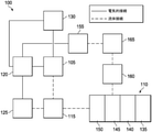
図1は、本明細書に係る、組織部位への局所処置溶液の点滴注入を伴う陰圧療法を提供することができる、治療システム100の例示的な実施形態の簡略化された機能ブロック図である。
I. Treatment System FIG. 1 is a simplified functional block of an exemplary embodiment of
これに関連して、用語「組織部位」は、骨組織、脂肪組織、筋組織、神経組織、真皮組織、血管組織、結合組織、軟骨、腱、又は靭帯を含むがこれらに限定されない組織上にある又は組織内にある、創傷、欠損、又は他の処置標的を広範に指す。創傷は、例えば、慢性の、急性の、外傷性の、亜急性の、及び裂開した創傷、中間層熱傷、潰瘍(糖尿病潰瘍、圧迫潰瘍、又は静脈不全潰瘍など)、弁状創、及び移植組織を含み得る。用語「組織部位」はまた、必ずしも創傷部又は欠損部ではなく、代わりに、追加的組織の成長を追加又は促進することが望ましいであろう、任意の組織の領域を指す場合もある。例えば、採取して移植することが可能な追加的組織を成長させるために、組織部位に陰圧を印加することができる。 In this regard, the term "tissue site" is used on tissues including, but not limited to, bone tissue, adipose tissue, muscle tissue, nerve tissue, dermal tissue, vascular tissue, connective tissue, cartilage, tendon, or ligament. Extensively refers to wounds, defects, or other treatment targets that are or are in tissue. Wounds include, for example, chronic, acute, traumatic, subacute, and dehiscenced wounds, middle layer burns, ulcers (such as diabetic ulcers, compression ulcers, or venous insufficiency ulcers), valvular wounds, and transplants. May include tissue. The term "tissue site" may also refer to any area of tissue where it may be desirable to add or promote the growth of additional tissue instead, not necessarily the wound or defect. For example, negative pressure can be applied to the tissue site to grow additional tissue that can be harvested and transplanted.
治療システム100は、例えば、陰圧源105などの陰圧源又は陰圧供給源と、ドレッシング110と、容器115などの流体容器と、コントローラ120などの調整器又はコントローラとを含むことができる。更に、治療システム100は、動作パラメータを測定して動作パラメータを示すフィードバック信号をコントローラ120に提供する、センサを含んでもよい。図1に示すように、例えば、治療システム100は、コントローラ120に連結された第1のセンサ125、第2のセンサ130、又は双方を含むことができる。図1の実施例に示されるように、ドレッシング110は、創傷清拭マトリックス135、接触層140、保持層145、及びカバー層150のいくつかの組み合わせを含むか、又は本質的にいくつかの組み合わせからなっていてもよい。
The
治療システム100はまた、点滴注入溶液源を含んでもよい。例えば、溶液源165は、図1の例示的な実施形態に示されるように、ドレッシング110に流体結合されてもよい。溶液源165は、いくつかの実施形態では、陽圧源155などの陽圧源、陰圧源105などの陰圧源、又は双方に流体結合されてもよい。点滴注入調整器160などの調整器もまた、溶液源165及びドレッシング110に流体結合され、組織部位への点滴注入溶液(例えば、生理食塩水)の適切な投与を確実にしてもよい。例えば、点滴注入調整器160は、陰圧源105によって空気圧で作動され得るピストンを備え、陰圧期間中に溶液源から点滴注入溶液を引き出し、通気期間中に溶液をドレッシングに点滴注入することができる。追加的又は代替的に、コントローラ120は、陰圧源105、陽圧源155、又は双方に結合され、組織部位への点滴注入溶液の投与を制御し得る。いくつかの実施形態では、点滴注入調整器160はまた、図1の実施例に示すように、ドレッシング110を通して陰圧源105に流体結合されてもよい。
The
封止治療環境内などの、別の構成要素又は場所における圧力を低下させるために陰圧源を使用する流体力学は、数学的に複雑となり得る。しかし、陰圧療法及び点滴注入に適用可能な流体力学の基本原理は、概して、当業者に周知であり、圧力を低減するプロセスは、例えば、陰圧を「送達する」、「分配する」、又は「生成する」ものとして本明細書で例示的に説明され得る。 Fluid dynamics using a negative pressure source to reduce pressure at another component or location, such as within a sealed treatment environment, can be mathematically complex. However, the basic principles of fluid mechanics applicable to negative pressure therapy and infusion are generally well known to those of skill in the art, and the process of reducing pressure is, for example, "delivering", "distributing", negative pressure. Alternatively, it may be exemplified herein as "producing".
一般に、滲出液及び他の流体は、流体経路に沿って低圧に向かって流れる。したがって、「下流」という用語は、典型的には、陰圧源に比較的より近い、又は陽圧源からより遠く離れている流体経路内のものを意味する。逆に、「上流」という用語は、陰圧源から比較的より遠く離れているか、又は陽圧源により近いものを意味する。同様に、かかる基準系における流体の「入口」又は「出口」の観点から特定の特徴を説明することが便利であり得る。この向きは、一般に、本明細書におけるさまざまな特徴及び構成要素を説明する目的のために想定される。しかし、用途によっては、流体経路を逆転してもよく(例えば陰圧源の代わりに陽圧源を使用することによって、など)、この記述上の取り決めは、限定的な取り決めと解釈されるべきではない。 In general, exudates and other fluids flow towards low pressure along the fluid path. Thus, the term "downstream" typically means within a fluid path that is relatively closer to the negative pressure source or farther away from the positive pressure source. Conversely, the term "upstream" means something that is relatively farther from the negative pressure source or closer to the positive pressure source. Similarly, it may be convenient to describe certain features in terms of the "inlet" or "outlet" of the fluid in such a frame of reference. This orientation is generally envisioned for the purposes of describing the various features and components herein. However, in some applications, the fluid path may be reversed (eg, by using a positive pressure source instead of a negative pressure source), and this descriptive arrangement should be construed as a limited arrangement. is not it.
治療システム100のいくつかの構成要素は、センサ、処理ユニット、アラームインジケータ、メモリ、データベース、ソフトウェア、表示デバイス、又は治療を更に促進するユーザインターフェース、などの他の構成要素内に収容されるか、又はそれらと併せて使用されてもよい。例えば、いくつかの実施形態では、陰圧源105は、溶液源165、コントローラ120、及び他の構成要素と組み合わせて治療ユニットにすることができる。
Some components of the
一般に、治療システム100の構成要素は、直接的又は間接的に結合されてもよい。例えば、陰圧源105は、容器115に直接結合されてもよく、容器115を通してドレッシング110に間接的に結合されてもよい。結合としては、流体、機械的、熱的、電気的、若しくは化学的結合(化学結合など)、又は、文脈によっては、結合のいくつかの組み合わせを挙げることができる。例えば、陰圧源105は、コントローラ120に電気的に結合されてもよく、組織部位への流体経路を提供するために1つ以上の分配構成要素に流体結合されてもよい。いくつかの実施形態では、構成要素はまた、物理的近接性によって結合されてもよく、単一構造に一体化されてもよく、又は同じ材料片から形成されてもよい。
In general, the components of the
分配構成要素は、取り外し可能であってもよく、又は使い捨て、再使用可能、若しくはリサイクル可能であってもよい。ドレッシング110及び容器115は、分配構成要素の例示である。流体導管は、分配構成要素の別の例示的な実施例である。「流体導管」は、この文脈では、チューブ、パイプ、ホース、導管、又は2つの端部間で流体を運ぶように適合された1つ以上の内腔又は開放経路を有する他の構造を広く含む。典型的には、チューブは、いくらかの可撓性を有する細長い円筒構造であるが、幾何学形状及び剛性は変化してもよい。更に、いくつかの流体導管は、他の構成要素の中へ成形されてもよく、そうでなければ他の構成要素と一体的に組み合わされてもよい。分配構成要素はまた、他の構成要素の結合及び分離を促進するために、インターフェース又は流体ポートを含むか、又は備えてもよい。いくつかの実施形態では、例えば、ドレッシングインターフェースは、流体導管をドレッシング110に結合することを容易にしてもよい。例えば、かかるドレッシングインターフェースは、San Antonio、TexasのKCIから入手可能なSENSAT.R.A.C.(商標)Padであってもよい。
The distribution component may be removable, or disposable, reusable, or recyclable. The dressing 110 and the
A.ドレッシング
図2A及び図2Bは、ドレッシング110の一実施例の概略断面図であり、いくつかの実施形態に関連し得る更なる詳細を示す。図2Aは、接触層140の実施例及び保持層145の実施例を含む。いくつかの実施形態では、図2Aに示されるように、カバー層150は、1つ以上の他の層の上に配置されてもよい。
A. Dressing FIGS. 2A and 2B are schematic cross-sectional views of an embodiment of the dressing 110, showing further details that may be relevant to some embodiments. FIG. 2A includes an embodiment of the
接触層140は、概して、組織部位に部分的又は完全に接触するように適合されることができる。接触層140は、多くの形態をとることができ、実施される処置のタイプ又は組織部位の性質及びサイズなどのさまざまな要因に応じて、多くのサイズ、形状、又は厚さを有することができる。例えば、接触層140のサイズ及び形状は、深く不規則な形状の組織部位の輪郭に適合されてもよい。更に、接触層140の表面のいずれか又は全ては、組織部位にひずみ及び応力を誘起することができる突起又は不均一な、粗い、若しくはギザギザの外形を有してもよく、これによって、組織部位における肉芽形成を促進することができる。
The
いくつかの実施形態では、接触層140は、マニホールドであってもよい。この文脈における「マニホールド」は、一般に、圧力下で組織部位にわたって流体を収集又は分配するように適合された複数の経路を提供する任意の物質又は構造を含む。例えば、マニホールドは、供給源から陰圧を受容し、組織部位にわたって複数の開口を通して陰圧を分配するように適合されていてもよく、これは、組織部位にわたって流体を収集し、供給源に向かって流体を引き寄せる効果を有してもよい。いくつかの実施形態では、流体経路は、逆転させることができ、又は二次流体経路が、点滴注入溶液源から組織部位にわたってなど、流体の送達を促進するために提供されてもよい。
In some embodiments, the
いくつかの例示的な実施形態では、マニホールドの経路は、組織部位にわたる流体の分配又は収集を改善するために相互接続されてもよい。いくつかの例示的な実施形態では、マニホールドは、相互接続された気泡又は細孔を有する多孔質材料であってもよい。例えば、多孔性発泡体、連続気泡発泡体、網状発泡体、多孔質組織集合体、及びガーゼ又はフェルトのマットなどの他の多孔質材料は、一般に、相互接続された流体通路を形成するように適合された細孔、縁、及び/又は壁を含む。液体、ゲル、及び他の発泡体もまた、開口及び流体経路を含み得るか、又は含むように硬化させることもできる。他の実施形態では、穿孔された独立気泡発泡体が好適であってもよい。例えば、接触層140のいくつかの実施形態は、穴を有する独立気泡架橋ポリオレフィン発泡体を含むか、又はそれから成ってもよい。いくつかの実施形態では、マニホールドは、追加的又は代替的に、相互接続された流体経路を形成する突起を備えてもよい。例えば、マニホールドは、相互接続された流体経路を画定する表面突起を設けるように、成形することができる。
In some exemplary embodiments, the manifold pathways may be interconnected to improve fluid distribution or collection across tissue sites. In some exemplary embodiments, the manifold may be a porous material with interconnected bubbles or pores. For example, other porous materials such as porous foams, open cell foams, reticulated foams, porous tissue aggregates, and mats of gauze or felt generally form interconnected fluid passages. Includes adapted pores, edges, and / or walls. Liquids, gels, and other foams can also contain or cure to include openings and fluid pathways. In other embodiments, perforated closed cell foams may be preferred. For example, some embodiments of the
発泡体の平均気泡サイズは、所定の治療の必要性に従って変化してもよい。例えば、いくつかの実施形態では、接触層140は、400~600ミクロンの範囲の細孔径を有する発泡体であってもよい。接触層140の引張強度はまた、所定の治療の必要性に従って変化してもよい。例えば、発泡体の引張強度は、局所処置溶液の点滴注入のために増加されてもよい。いくつかの実施例では、接触層140は、GRANUFOAM(商標)ドレッシング又はV.A.C.VERAFLO(商標)ドレッシングに見出されるような網状ポリウレタン発泡体であってもよく、双方ともSan Antonio、TexasのKCIから入手可能である。
The average bubble size of the foam may vary according to the need for a given treatment. For example, in some embodiments, the
いくつかの実施形態では、接触層140は、機械的又は化学的に圧縮されて周囲圧力で密度が増加する材料から形成されてもよい。例えば、接触層140は、圧縮された発泡体などの圧縮性材料を含むか、又は圧縮性材料から成ってもよい。圧縮された発泡体は、圧縮された状態の発泡体の密度と圧縮されていない状態の同じ発泡体の密度との比として定義される硬度係数(firmness factor)によって特徴付けられてもよい。いくつかの実施形態では、接触層140は、約1~約10の硬度係数を有してもよい。例えば、圧縮されていない状態の同じ発泡体の密度よりも5倍大きい密度を有する圧縮された発泡体は、硬度係数5を有するものとして特徴付けることができる。発泡体の硬度係数を増加させると、発泡体の厚さに平行な方向における発泡体の剛性が増加することができる。例えば、接触層140の硬度係数を増加させることにより、接触層140の厚さに平行な方向における接触層140の剛性を増加させることができる。いくつかの実施形態では、接触層140は、圧縮された網状ポリウレタン発泡体を含むか、又はそれから成ってもよく、その圧縮されていない状態で約0.03グラム/センチメートル3(g/cm3)の密度を有してもよい。発泡体が硬度係数5を有するように圧縮される場合、発泡体は、発泡体の密度が約0.15g/cm3になるまで圧縮されてもよい。いくつかの実施形態では、接触層140は、周囲圧力で約4ミリメートル~約15ミリメートル、より具体的には約8ミリメートルの厚さを有する圧縮された発泡体を含むか、又はそれから成っていてもよい。
In some embodiments, the
一般に、圧縮された発泡体は、同様の圧縮されていない発泡体よりも陰圧下での変形が少ない。変形の減少は、硬度係数によって反映される剛性の増加によって引き起こされてもよい。陰圧の応力を受けた場合、圧縮された発泡体は、同様の材料の圧縮されていない発泡体よりも平らになりにくい可能性がある。いくつかの実施例では、接触層140の厚さが周囲圧力で約8ミリメートルである場合、接触層140は、治療レベルの陰圧下で約1ミリメートル~約5ミリメートルの厚さを有してもよく、概して、約3ミリメートル超であってもよい。発泡体の厚さに平行な方向に圧縮された発泡体の剛性により、発泡体は、厚さに垂直な方向などの他の方向において、柔軟性又は圧縮性がより高くなることができる。
In general, compressed foams are less deformed under negative pressure than similar uncompressed foams. The decrease in deformation may be caused by an increase in stiffness reflected by the hardness factor. Under negative pressure stress, compressed foam may be less likely to flatten than uncompressed foam of similar material. In some embodiments, where the thickness of the
接触層140は、疎水性であっても親水性であってもよい。接触層140が親水性であり得る実施例では、接触層140はまた、組織部位に陰圧を分配し続けながら、組織部位から流体を吸い上げることができる。接触層140のウィッキング特性は、毛細管流又は他のウィッキング機構によって組織部位から流体を引き離すことができる。親水性発泡体の例は、San Antonio、TexasのKCIから入手可能なV.A.C.WHITEFOAM(商標)ドレッシングなどのポリビニルアルコールの連続気泡発泡体である。他の親水性発泡体としては、ポリエーテルから作製されるものが挙げることができる。親水性特性を呈し得る他の発泡体としては、親水性を付与するように処理又はコーティングされた疎水性発泡体が挙げられる。
The
接触層140は、封止治療環境内の圧力が低下したときに、組織部位における肉芽形成を更に促進することができる。例えば、接触層140の表面のいずれか又は全ては、接触層140を通して陰圧が印加される場合、組織部位において微小ひずみ及び応力を誘発し得る、不均一な、粗い、又はギザギザの外形を有してもよい。
The
いくつかの実施形態では、接触層140は、再吸収性又は生体再吸収性の材料から構成されてもよい。本明細書で使用される場合、「再吸収性」又は「生体再吸収性」という用語は同義であり、例えば組織部位又は哺乳動物体内の生体内で材料の少なくとも一部が吸収又は同化されるように、材料の少なくとも一部が生理流体又はプロセスに曝される際に、崩壊、分解又は溶解する能力を示す。再吸収性又は生体再吸収性は、化学的プロセス若しくは条件、物理的プロセス若しくは条件、又はそれらの組み合わせの結果として呈され得る。好適な生体再吸収性材料としては、ポリ乳酸(PLA)及びポリグリコール酸(PGA)とのポリマーブレンドを挙げることができるが、これらに限定されない。ポリマーブレンドはまた、ポリカーボネート、ポリフマレート、及びカプララクトンを含んでもよいが、これらに限定されない。接触層140は、新しい細胞増殖のための足場として更に機能してもよく、又は細胞増殖を促進するために接触層140と併せて足場材料を使用してもよい。足場とは一般に、細胞増殖のためのテンプレートを提供する3次元多孔質構造体などの、細胞の増殖又は組織の形成を強化若しくは促進するために使用される、物質又は構造体である。足場材料の例示的な実施例としては、リン酸カルシウム、コラーゲン、PLA/PGA、コーラル(coral)ヒドロキシアパタイト、炭酸塩、又は、加工処理された同種移植片材料が挙げられる。
In some embodiments, the
いくつかの実施形態では、接触層140は、スチレンエチレンブチレンスチレン(SEBS)コポリマーなどの熱可塑性エラストマー(TPE)、又は熱可塑性ポリウレタン(TPU)から形成されてもよい。接触層140は、TPE又はTPUのシートを組み合わせることによって形成してもよい。いくつかの実施形態では、TPE又はTPUのシートは、互いに接合、溶接、接着、又は別の方法で結合されてもよい。例えば、いくつかの実施形態では、TPE又はTPUのシートは、放射熱、高周波溶接、又はレーザ溶接を使用して溶接されてもよい。Supracor,Inc.、Hexacor,Ltd.、Hexcel Corp.、及びEconocorp,Inc.は、接触層140の形成に適したTPE又はTPUシートを製造することができる。いくつかの実施形態では、約0.2mm~約2.0mmの厚さを有するTPE又はTPUのシートを使用して、接触層140に適した構造体を形成することができる。いくつかの実施形態では、接触層140は、スペーサファブリックとも称される3D織物から形成されてもよい。適切な3D織物は、Heathcoat Fabrics,Ltd.、Baltex、及びMueller Textil Groupによって製造され得る。接触層140はまた、フェルト発泡体、ポリウレタン、シリコーン、ポリビニルアルコール、及び銅、スズ、銀、又は他の有益な金属などの金属から形成することもできる。
In some embodiments, the
いくつかの実施形態では、接触層140は、実質的に均一な厚さを有し得る。約5.0mm~約20mm又は約5.0mm~約20mmの厚さが、いくつかの構成に好適であってよい。例えば、接触層140のいくつかの実施形態は、約8ミリメートルの厚さを有してもよい。いくつかの実施形態では、厚さは厳密に均一でなくてもよい。例えば、いくつかの実施形態では、約2ミリメートルの公差が好適であってよい。
In some embodiments, the
いくつかの実施形態では、接触層140は、1つ以上の穴、空洞、又は凹部を有することができる。一般に、穴205は、接触層140を通って延びてよい。例えば、図2Aでは、接触層140は、接触層を通って延び得る1つ以上の穴205を有する。いくつかの実施例では、1mm~40mmの高さ又は深さ及び1mm~30mmの幅が好適であってよい。いくつかの実施形態では、約8mmの深さが好適であってよい。図2Aに示されるように、穴205のうちの1つ以上又は全ては、第1の表面210から第2の表面215まで接触層140を通って延びる貫通穴であってもよい。いくつかの実施例では、穴205は、接触層140を穿孔することによって、又は射出成形によって形成することができる。穴205は、接触層140の壁220によって形成することができる。
In some embodiments, the
他の実施形態では、穴205のうちの1つ以上は、接触層140を完全には貫通しない止まり穴又は他の凹部であってもよい。例えば、穴のうちの1つ以上は、第1の表面210から接触層140の中へ延び、接触層140の厚さ未満の深さを有してもよい。
In other embodiments, one or more of the
穴205は、接触層140内の壁220によって画定されてもよい。いくつかの実施形態では、壁220の内面は、接触層140の第1の表面210及び第2の表面215に略垂直であってもよい。更に他の実施形態では、壁220は、接触層140の第1の表面210と第2の表面215との間に実質的に滑らかな表面を有することができる。更に他の実施形態では、穴205は、テーパ状であってもよく、円錐形、ピラミッド形、又は他の不規則な幾何学形状を有してもよい。いくつかの実施形態では、穴205は、穴205の各穴の中心軸が第1の表面210、第2の表面215、又は双方に直交するように形成されてもよい。他の実施形態では、穴205のうちの1つ以上は、中心軸が第1の表面210、第2の表面215、又は双方に対して斜めになるように形成されてもよい。
The
いくつかの実施形態では、保持層145は、1つ以上の突起、突出部、結節、又は隆起を有してもよい。図2Aの実施例に示されるように、保持層145は、接触層140の穴205のうちの1つ以上の中へ突出するか又は突出するように構成された突起225を有してもよい。保持層145は、網状発泡体などの発泡体から作製することができる。いくつかの実施例では、保持層145は、比較的大きい細孔径を有する連続気泡発泡体で作製されてもよい。いくつかの実施例では、1インチ当たり10~80個の細孔の平均細孔径が好適であってもよい。保持層145は、可撓性、半剛性、又は剛性であってもよい。いくつかの実施形態では、保持層145は、接触層140よりも可撓性又は圧縮性が高くてもよい。更なる実施形態では、保持層145は、接触層140よりも密度が低くてもよい。特定の実施形態では、保持層145は、接触層140よりも厚さが薄くてもよい。
In some embodiments, the
いくつかの実施形態では、突起225は、保持層145から延びる一体部分として形成されてもよい。他の実施例では、突起225は、保持層145に結合されてもよい。突起225は、網状発泡体などの発泡体から作製することができる。いくつかの実施形態では、突起225は、保持層145から穴205の中へ突出してもよい。いくつかの実施例では、突起225の深さは、穴205の深さよりも小さい。例えば、穴205が約8ミリメートルの深さを有する場合、突起225は約6ミリメートルの深さを有することができる。いくつかの実施形態では、1mm~30mmの深さが好適であってもよい。いくつかの実施形態では、突起225は、1~30mm(例えば、10mm)の直径を有することができる。追加的又は代替的に、突起225は、接触層140内の穴205の形状と相補的である形状を有してもよい。非限定的な例示的な実施形態では、突起225は、三角形、台形、楕円形、菱形、長方形、卵形、正方形、円形、八角形、又は他の好適な形状などの形状を有してもよい。
In some embodiments, the
いくつかの実施形態では、突起225は、穴205の一部又は全部を少なくとも部分的に充填することができる。あるいは、突起225は、穴205の一部又は全部を実質的に充填してもよい。例えば、突起225の少なくともいくつかは、穴205内に配置されたテーパ状端部を有することができる。いくつかの実施形態では、突起225と接触層140との間に空間230があってもよい。いくつかの実施例では、突起225は、でこぼこの外面などの均一又は不均一な外面を有してもよい。
In some embodiments, the
いくつかの実施形態では、カバー層150は、図2Aの実施例に示すように、保持層145に隣接して配置することができる。カバー層150によって、物理的外傷からの細菌バリア及び保護を得ることができる。いくつかの実施形態では、カバー層150はまた、蒸発損失を低減し、治療環境と局所外部環境との間など、2つの構成要素又は2つの環境間に流体シールを提供することができる材料から構成されてもよい。カバー層150は、例えば、所定の陰圧源に対して、組織部位において陰圧を維持するのに十分なシールを提供することができるエラストマーフィルム又は膜であってもよい。カバー層150は、いくつかの用途において、高い水蒸気透過率(MVTR)を有してもよい。例えば、いくつかの実施形態では、MVTRは24時間当たり少なくとも300g/m2であってもよい。いくつかの例示的な実施形態では、カバー層150は、水蒸気に対して透過性を有するが、液体に対しては不透過性であるポリウレタンフィルムなどのポリマードレープとすることができる。かかるドレープは、典型的には、25~50ミクロンの範囲の厚さを有する。透過性材料の場合、透過性は一般に、所望の陰圧を維持することができるほど十分に低いべきである。
In some embodiments, the
いくつかの実施形態では、接触層140及び保持層145は、1つの構成要素又は一体層に一体化されてもよく、分離不可能であってもよい。例えば、いくつかの実施形態では、保持層145を接触層140に積層することができる。
In some embodiments, the
いくつかの実施形態では、追加の層又は構成要素がドレッシング内に存在してもよい。例えば、少なくとも1つの更なる層又は構成要素が、接触層140と創傷清拭マトリックス135との間に存在してもよく、少なくとも1つの更なる層又は構成要素が、接触層140に隣接する創傷清拭マトリックス135の表面と反対側の創傷清拭マトリックス135の表面に隣接して存在してもよく、及び/又は少なくとも1つの更なる層又は構成要素が、創傷清拭マトリックス135に隣接する接触層140の表面と反対側の接触層140の表面に隣接して存在してもよい。
In some embodiments, additional layers or components may be present within the dressing. For example, at least one additional layer or component may be present between the
図2Bは、カバー層150が保持層145に直接結合されていないドレッシング110の別の実施例の概略図である。図2Bに示されるように、充填剤層235は、任意に、保持層145とカバー層150との間に配置されてもよい。例えば、充填剤層235は、ドレッシング110の深さを増加させるために、保持層145に隣接して配置することができる。また、図2Bに示されるように、いくつかの実施形態では、創傷清拭マトリックス135は、任意に、接触層140の表面に隣接して配置されるか、又は接着されることができる。例えば、創傷清拭マトリックス135は、接触層140上に接着、固定、締結、又は接合され得る、連続的又は非連続的なコーティング、フィルム、ゲル、層及び/又はシートの形態であってもよい。いくつかの実施形態では、創傷清拭マトリックス135は、接触層140の表面の少なくとも一部分上のコーティングであってもよく、例えば、創傷清拭マトリックス135は、接触層140の表面の少なくとも約10%、少なくとも約25%、少なくとも約50%、少なくとも約75%、又は少なくとも約95%上にコーティングすることができる。いくつかの実施形態では、創傷清拭マトリックス135は、接触層140の実質的に全表面上のコーティングであってもよく、例えば、創傷清拭マトリックス135は、接触層140の表面の少なくとも約99%、99.9%、又は約100%上にコーティングされてもよい。
FIG. 2B is a schematic representation of another embodiment of the dressing 110 in which the
いくつかの実施形態では、創傷清拭マトリックス135は、穴205の一部のみを覆ってもよく、したがって、穴205の少なくとも一部は、創傷清拭マトリックス135によって覆われなくてもよい。他の実施形態では、創傷清拭マトリックス135は、図2Bの実施例に示すように穴205を覆う固体シートであってもよい。他の実施形態では、創傷清拭マトリックス135は、穴205の少なくとも一部を少なくとも部分的に充填してもよく、又は、穴205の実質的に全てを少なくとも部分的に充填してもよい。あるいは、創傷清拭マトリックス135は、穴205の少なくとも一部を実質的に充填してもよく、又は穴205の実質的に全てを実質的に充填してもよい。いくつかの実施形態では、創傷清拭マトリックス135は、接触層140から少なくとも部分的に取り外し可能又は分離可能であってもよい。例えば、創傷清拭マトリックス135を接触層140から取り外し、組織部位に直接適用することができる。
In some embodiments, the
創傷清拭マトリックス135の厚さは変化してもよい。いくつかの実施形態では、約1.0mm~約10mm、約1.0mm~約5.0mm、又は約1.0mm~約3.0mmの範囲の厚さが好適であってよい。いくつかの実施形態では、創傷清拭マトリックス135は、多孔質であってもよく、又は穴、スリット、開窓、流体経路、若しくは創傷清拭マトリックス135を通る流体流れのための他の手段を有してもよい。
The thickness of the
さまざまな実施形態において、創傷清拭マトリックス135は、少なくとも1種類の創傷清拭剤及びポリマーを含んでもよい。いくつかの実施形態では、創傷清拭マトリックス135は、約2~約10のpH、又はより低いpH、例えば、約1.0~約6.0のpH、約2.0~約5.0のpH、又は約2.5~約4.0のpHを有してもよく、より低いpHは、創傷治癒を更に援助してもよい。創傷清拭剤は、組織部位又は創傷を清拭することができる任意の酵素であってもよい。本明細書中で使用される場合、用語「創傷清拭(debriding)」又は「デブリードマン(debridement)」とは、壊死組織、バイオフィルム、スラフ、エスカー、及び、組織部位、例えば、創傷由来の他の破片などの組織及び/又は細胞の軟化、弱体化、除去、剥離及び/又は破壊を指し、これによって、治癒を促進し、かつ/又は感染の危険性を減少することができる。いくつかの実施形態では、創傷清拭剤は、有利には、例えば、組織部位又は創傷内で、広いpH範囲、例えば、約2~約12、又は約2~約10のpHにわたって活性(即ち、組織のデブリードマン又は破壊を引き起こす)であってよい。創傷清拭剤は、さまざまな濃度及び/又は米国薬局方単位(USP単位)の活性で、例えば、約0.25USP単位~約1,000USP単位、約0.25USP単位~約500USP単位、約0.25USP単位~約300USP単位、又は約30USP単位~約300USP単位で存在してもよい。いくつかの実施形態では、創傷清拭剤は、デブリードマンを強化するために、有利には、より高い濃度及び/又はUSP単位の活性で存在してもよい。いくつかの実施形態では、創傷清拭剤は、パパイン、尿素、ストレプトキナーゼ、ストレプトドルナーゼ、トリプシン、コラゲナーゼ、フィブリノリジン、デオキシリボヌクレアーゼ(DNase)、DNaseを伴うフィブリノリジン(フィブリノリジン/DNase)、ブロメライン、及びこれらの組み合わせからなる群から選択することができる。
In various embodiments, the
ポリマーは、その中に創傷清拭剤を固定化するための任意の適切な有機ポリマーとすることができる。更に、ポリマーは生分解性であってもよい。本明細書で使用される場合、用語「生分解性」とは、例えば、組織部位及び/又は生理学的流体若しくはプロセスへの曝露の際に、化学的及び/又は物理的に劣化又は分解し得る材料に関する。「生分解」としては、引き裂き、分解、切断、破砕、溶解、解離などが挙げられる。「可溶性」、「溶解可能」、「解離可能」、「引き裂き可能」、「分解可能」、「切断可能」、「破砕可能」、「破壊可能」などの用語を使用してもよく、これらは生分解可能な材料に関する。生分解は、化学的プロセス若しくは条件、物理的プロセス若しくは条件、又はそれらの組み合わせの結果として呈され得る。好適なポリマーの例としては、多糖類(例えば、柑橘類果実ペクチン、スターチ、澱粉、寒天)、タンパク質(例えば、コラーゲン、ゼラチン、アルブミン)、植物ガム(例えば、キサンタンガム、ローカストビーン、グアー)、及びこれらの組み合わせが挙げられるが、これらに限定されない。追加的又は代替的に、ポリマーは生体再吸収性であってもよい。 The polymer can be any suitable organic polymer for immobilizing the wound cleaning agent therein. In addition, the polymer may be biodegradable. As used herein, the term "biodegradable" can be chemically and / or physically degraded or degraded, for example, upon exposure to tissue sites and / or physiological fluids or processes. Regarding materials. Examples of "biodegradation" include tearing, decomposition, cutting, crushing, dissolution, dissociation and the like. Terms such as "soluble," "dissolvable," "dissociable," "tearable," "degradable," "cuttable," "crushable," and "destructible" may be used. Regarding biodegradable materials. Biodegradation can be exhibited as a result of chemical processes or conditions, physical processes or conditions, or a combination thereof. Examples of suitable polymers include polysaccharides (eg, citrus fruit pectin, starch, starch, agar), proteins (eg, collagen, gelatin, albumin), plant gums (eg, xanthan gum, locust beans, guar), and these. Combinations of, but are not limited to these. In addition or alternatives, the polymer may be bioreabsorptive.
使用中、例えば、点滴注入サイクル中の所望の溶解度に応じて、ポリマーは、少なくとも約10%、例えば、約10%~約90%又は10%~約70%の可溶性固体組成物を有してもよい。例えば、ポリマーの少なくとも約10%は、例えば約2~約10のpHを有する水溶液に可溶性であり得る。ポリマー及び/又は創傷清拭マトリックス135は、使用中に、例えば、組織部位と接触して創傷清拭剤を放出するときに、生分解又は溶解することができ、これにより組織部位を創傷清拭することができる。ポリマーの完全な生分解又は溶解は、組織部位の創傷清拭が起こるのに必要ではない。むしろ、組織部位の創傷清拭は、以下のうちの1つ以上中に生じ得る:創傷清拭マトリックス135が最初に組織部位に接触するとき;ポリマーが生分解又は溶解する間;ポリマーが生分解又は溶解を停止次第;及びポリマーが実質的に生分解又は溶解した後。ポリマーの生分解又は溶解、創傷清拭剤の放出及び/又は組織部位の創傷清拭に続いて、創傷清拭剤及び任意の残留ポリマーは、有利には、例えば所望の時間間隔での点滴注入療法中に、任意の創傷の破片とともに洗い流され得る。いくつかの実施形態では、ポリマー及び/又は創傷清拭マトリックス135は、さまざまな速度で、例えば、所望通りに速く又はゆっくりと溶解することができる。例えば、ポリマー及び/又は創傷清拭マトリックス135は、例えば1つの治療サイクル中に数分(例えば、1、2、3、4、5分など)で溶解してもよく、あるいは、ポリマー及び/又は創傷清拭マトリックス135は、例えば治療が終わるまで、1日以上の経過にわたって溶解してもよい。
During use, for example, depending on the desired solubility during the infusion cycle, the polymer has at least about 10%, eg, about 10% to about 90% or 10% to about 70% soluble solid composition. May be good. For example, at least about 10% of the polymer may be soluble in an aqueous solution having a pH of, for example, about 2 to about 10. The polymer and / or the
いくつかの実施形態では、創傷清拭マトリックス135は、乾燥剤、増粘剤、及び徐放剤のうちの1つ以上をさまざまな量で更に含んでもよい。好適な乾燥剤の例としては、シリカゲル(例えば、シリカキセロゲル、シリカゲル繊維)、ケイ酸アルミニウムマグネシウム、酸化カルシウム、硫酸カルシウム、スルホネート、及びこれらの組み合わせが挙げられるが、これらに限定されない。好適な増粘剤の例としては、グリセロール、グリセリン、カルボマー、ポリエチレングリコール及びそれらの組み合わせが挙げられるが、これらに限定されない。理論に束縛されるものではないが、乾燥剤及び/又は増粘剤は、表面乾燥作用及び/又は変性作用を発揮することによって、創傷破片の破壊、除去又は剥離を援助することができると考えられる。かかる乾燥活性及び/又は変性活性は、ドレッシングの機械的作用とともに、創傷破片の破壊、除去、又は剥離における共作用又は相乗作用を呈してもよい。
In some embodiments, the
他の実施形態では、創傷清拭マトリックス135は、酸化セルロースを更に含んでもよい。「酸化セルロース」という用語は、例えば四酸化二窒素によるセルロースの酸化によって生成される任意の材料を指す。かかる酸化は、糖類残基上の第一級アルコール基をカルボン酸基に変換し、セルロース鎖内にウロン酸残基を形成する。酸化は、一般的に、完全な選択性では進行せず、結果として、炭素2及び3上のヒドロキシル基は、ケト形態に時折変換される。これらのケト単位は、アルカリ不安定な結合を導入し、これはpH7以上で、ラクトン及び糖環開裂の形成によってポリマーの分解を開始する。結果として、酸化セルロースは、生理的条件下で生分解性及び再吸収性又は生体再吸収性である。いくつかの実施形態では、創傷清拭マトリックス135内に存在する酸化セルロースは、レーヨンなどの再生セルロースの酸化によって調製され得る酸化再生セルロース(ORC)であってもよい。ORCは、止血特性を有することが知られている。ORCは、1950年以来、SURGICEL(登録商標)(Johnson & Johnson Medical,Inc.)と呼ばれる止血布として入手可能である。この製品は、編まれたレーヨン材料の酸化によって製造され得る。いくつかの実施形態では、創傷清拭マトリックス135は、接触層140に動作可能に結合されてもよい。
In other embodiments, the
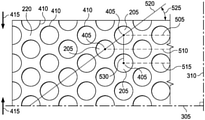
図3は、接触層140の一実施例の平面図であり、いくつかの実施形態に関連し得る更なる詳細を示す。例えば、穴205のいくつかの実施形態は、図3に示すような円形断面を有してもよい。いくつかの実施形態では、穴205は、約2.0mm超、約4.0mm超、約6.0mm超、約10mm超の平均直径、又は約5mm~約20mmの平均直径を有してもよく、いくつかの実施形態では、穴205の平均直径は、約10mm、又は約5mm~約15mmの範囲であってもよい。
FIG. 3 is a plan view of an embodiment of the
いくつかの実施形態では、接触層140は、第1の方向線305と、第1の方向線305に垂直な第2の方向線310とを有することができる。第1の方向線305及び第2の方向線310は、接触層140を通る対称線であってもよい。図3の実施例では、接触層140は、長手方向縁部315及び短手方向縁部320を有する略矩形形状を有する。いくつかの実施形態では、第1の方向線305は、長手方向縁部315に平行であってもよい。
In some embodiments, the
いくつかの実施形態では、接触層140の長手方向縁部315及び短手方向縁部320は、直線縁部でなくてもよい。例えば、穴205のうちの1つ以上は、長手方向縁部315又は短手方向縁部320と重なり、縁部が非線形プロファイルを有するようにすることができ、これにより、ドレッシング110に陰圧が印加されている間、ケラチノサイト移動の中断を低減し、再上皮化を強化することができる。
In some embodiments, the
接触層140はまた、さまざまな他の好適な形状を有してもよい。例えば、接触層140は、菱形、正方形、又は円形の形状を有し得る。いくつかの実施形態では、接触層140の形状は、組織部位の形状又は種類に適応するように選択することができる。例えば、接触層140は、卵形又は円形の組織部位に適応するように、卵形又は円形の形状を有してもよい。
The
図4は、図3の穴205のうちの1つの詳細図であり、いくつかの実施形態に関連付けられ得る更なる詳細を示す。図4の実施例に示すように、穴205のうちの1つ以上は、中心405及び外周410を含むことができる。穴205の各穴はまた、形状係数によって特徴付けることができる。形状係数は、第1の方向線305及び第2の方向線310に対する穴205の各穴の向きを表すことができる。一般に、形状係数は、所望の収縮方向に平行な最大寸法の1/2と、所望の収縮方向に垂直な最大寸法の1/2との比である。例えば、図4における所望の収縮方向は、横方向の力の方向としてベクトル415によって示されるように、第2の方向線310に平行であってもよい。第1の軸420は、第1の方向線305に平行に中心405を通過してもよく、第2の軸425は、第2の方向線310に平行に中心405を通って延びてもよい。穴205の各穴の形状係数は、中心405から外周410まで延びる第2の軸425上の第1の線分430と、中心405から外周410まで延びる第1の軸420上の第2の線分435との比として定義することができる。例えば、第1の線分430の長さが2.5mmであり、第2の線分435の長さが2.5mmである場合、形状係数は1となる。他の実施形態では、穴205は、他の形状及び向き、例えば、卵形、六角形、楕円形、円形、正方形、三角形、円錐形、又は無定形若しくは不規則あるいはそれらの組み合わせを有してもよく、形状係数が約0.5~約1.10の範囲であり得るように、第1の方向線305及び第2の方向線310に対して方向付けされていてもよい。
FIG. 4 is a detailed view of one of the
図5は、図3の穴205の一部の詳細図であり、いくつかの実施形態に関連し得る更なる詳細を示す。いくつかの実施形態では、穴205は、図5の例に示されるように、アレイを形成するように、平行な列、例えば2つ以上の平行な列に整列することができる。例えば、穴205のアレイは、第1の列505、第2の列510、及び第3の列515を含むことができる。いくつかの実施形態では、第1の列505などの列の2つ以上の穴205の外周410間の壁220の幅は、約5ミリメートルであってもよい。隣接する列、例えば、第1の列505及び第2の列510における穴205の各穴の中心405は、第1の方向線305に沿ってオフセットされているものとして特徴付けられてもよい。いくつかの実施形態では、隣接する列の穴205の各穴の中心405を通過する支線520は、第1の方向線305と支線角度525を画定することができる。いくつかの実施形態では、支線角度525は、約90°未満であってもよい。他の実施形態では、支線角度525は、約30°~約70°であってもよい。他の実施形態では、支線角度525は約66°であってもよい。一般に、支線角度525が減少するにつれて、第1の方向線305に平行な方向における接触層140の剛性が増加することができる。第1の方向線305に平行な接触層140の剛性を増加させると、第1の方向線305に垂直な接触層140の圧縮性を増加させることができる。
FIG. 5 is a partial detail view of the
いくつかの実施形態では、交互の列の穴205の各穴の中心405は、長さ530だけ第2の方向線310に平行に間隔があいていてもよい。いくつかの実施形態では、長さ530は、穴205の有効径よりも大きくてもよい。いくつかの実施形態では、長さ530は、約7mm~約25mmとすることができる。
In some embodiments, the
接触層140は、追加的又は代替的に、図1に示すように、接触層140の外周によって画定される面積に対する、穴205によって生成される第1の表面210内の空隙空間の比を反映する空隙率によって特徴付けられてもよい。一般に、空隙率は、取り扱い特性と可撓性との間の望ましいバランスを達成するように設計することができる。例えば、空隙率を増加させると、穴205の収縮特性を増加させることができ、また、接触層140の取り扱い特性を減少させ得る。約40%~約75%の空隙率は、いくつかの実施形態にとって好適であってよい。例えば、いくつかの実施形態は、約55%の空隙率を有してもよい。
The
いくつかの実施形態では、穴205は、約3ミリメートル~約20ミリメートルの有効径を有することができる。非円形領域の有効径は、非円形領域と同じ表面積を有する円形領域の直径である。いくつかの実施形態では、穴205のうちの1つ以上は、約3.5mmの有効径の非円形断面を有する。他の実施形態では、穴205は、約5mm~約20mmの有効径を有してもよい。
In some embodiments, the
一般に、穴205は、発泡プロセスによって形成されず、接触層140を形成する材料の細孔又は気泡と区別することができる。例えば、材料の単一の細孔又は気泡は、概して、接触層140を完全に通って延びるほど十分に大きくない。穴205の有効径は、接触層140を形成する材料の細孔又は気泡の有効径よりも一桁大きくてもよい。いくつかの実施形態では、穴の有効径は、約1mmより大きくてもよく、接触層140の材料は、約600ミクロン未満の細孔径を有する発泡体であってもよい。
In general, the
いくつかの実施形態では、穴205は、接触層140の成形中に形成されてもよい。他の実施形態では、穴205は、接触層140が形成された後に、接触層140を切削、溶融、穴あけ、又は蒸発させることによって形成されてもよい。例えば、貫通穴は、接触層140を完全に通る穴をリーマ加工、穴あけ、又はフライス加工することによって形成され得る。追加的又は代替的に、穴205を接触層140にレーザで切削してもよい。
In some embodiments, the
いくつかの実施形態では、穴205を形成すると、接触層140の材料を熱成形して、これによって、穴205の内面を非多孔質にし得る。例えば、接触層140に穴205をレーザで切削すると、接触層140の材料を塑性変形させて、穴205の内面上の任意の細孔を閉鎖し得る。代替的又は追加的に、穴205の滑らかな内面は、穴205に滑らかな材料を塗布又はコーティングすることによって形成されてもよい。いくつかの実施形態では、滑らかな内面は、穴205を通る接触層140の中への組織の内部成長を制限するか、さもなければ阻害することができる。
In some embodiments, the formation of the
穴205の形状は、応力の集中を変化させるために、接触層140の異なる実施形態において変化してもよい。例えば、図6は、接触層140の別の実施形態の平面図であり、穴205が横方向の力415を引き起こすことができる六角形の断面を有する更なる詳細を例示している。図7は、接触層140の別の実施例の平面図であり、穴205が楕円形又は卵形の断面及び横方向の力415を有する更なる詳細を示す。図8は、接触層140の別の実施例の平面図であり、穴205が三角形の断面及び横方向の力415を有する更なる詳細を示す。
The shape of the
B.陰圧供給部
陰圧源105などの陰圧供給部は、陰圧の空気のリザーバとしてもよく、あるいは、例えば、真空ポンプ、吸引ポンプ、多くの医療施設で利用可能な壁面吸引ポート、又はマイクロポンプなどの、手動若しくは電動のデバイスとすることもできる。「陰圧」とは、一般に、封止治療環境の外部の局所的環境における周囲圧力などの局所的周囲圧力よりも低い圧力を指す。多くの場合、局所的周囲圧力はまた、組織部位が位置している大気圧でもあり得る。あるいは、圧力は、組織部位における、組織に関連する静水圧よりも、低い場合もある。別途指示のない限り、本明細書で記述される圧力の値は、ゲージ圧である。陰圧の増加とは、典型的には、絶対圧力の減少を指すのに対して、陰圧の減少は、典型的には、絶対圧力の増加を指す。組織部位に印加される陰圧の大きさ及び性質は、治療要件に応じて変化し得るが、圧力は通常、粗い真空(rough vacuum)とも一般に称される低真空(low vacuum)、-5mmHg(-667Pa)~-500mmHg(-66.7kPa)である。一般的な治療範囲は、-50mmHg(-6.7kPa)~-300mmHg(-39.9kPa)である。
B. Negative pressure supply section A negative pressure supply section such as the
C.容器
容器115は、組織部位から引き出された滲出液及び他の流体を処理するために使用することが可能な、容器、キャニスタ、パウチ、又は他の貯留構成要素を表している。多くの環境において、流体の収集、貯留、及び廃棄のためには、剛性の容器が好ましいか又は必要とされる場合がある。他の環境において、流体は、剛性の容器に貯留されることなく、適切に廃棄される場合もあり、再使用可能な容器により、陰圧療法に関連する廃棄物及びコストを削減することも可能である。
D.コントローラ
コントローラ120などのコントローラは、陰圧源105などの、治療システム100の1つ以上の構成要素を動作させるようにプログラムされたマイクロプロセッサ又はコンピュータであってもよい。例えば、いくつかの実施形態では、コントローラ120は、治療システム100の1つ以上の動作パラメータを直接的若しくは間接的に制御するようにプログラムされたプロセッサコア及びメモリを含む集積回路を一般に備えるマイクロコントローラとすることができる。動作パラメータとしては、例えば、陰圧源105に印加される電力、陰圧源105によって生成される圧力、又は接触層140に分配される圧力を挙げることができる。コントローラ120は、フィードバック信号などの1つ以上の入力信号を受信するように構成され、入力信号に基づいて1つ以上の動作パラメータを修正するようにプログラムすることができる。
D. Controller The controller, such as the
E.センサ
第1のセンサ125又は第2のセンサ130などのセンサは、一般に、物理的現象又は特性を検出又は測定するように動作可能な任意の装置として当該技術分野において公知であり、一般に、検出又は測定された現象又は特性を示す信号を提供する。例えば、第1のセンサ125及び第2のセンサ130は、治療システム100の1つ以上の動作パラメータを測定するように構成することができる。いくつかの実施形態では、第1のセンサ125は、空気経路内の圧力を測定し、測定された圧力を示す信号に測定値を変換するように構成された変換器であってもよい。いくつかの実施形態では、例えば、第1のセンサ125は、ピエゾ抵抗歪みゲージであってもよい。いくつかの実施形態では、第2のセンサ130は、任意に、電圧又は電流などの、陰圧源105の動作パラメータを測定することができる。好ましくは、第1のセンサ125及び第2のセンサ130からの信号は、コントローラ120への入力信号として好適であるが、いくつかの実施形態では、ある信号調整が適切であってもよい。例えば、信号は、コントローラ120によって処理され得る前に、フィルタ処理又は増幅される必要があってもよい。典型的には、信号は電気信号であるが、光信号などの他の形態で表されてもよい。
E. Sensors Sensors, such as the
F.取付デバイス
カバー層150を、損傷を受けていない表皮、ガスケット、又は別のカバーなどの取付表面に取り付けるために、取付デバイスを使用することができる。取付デバイスは多くの形態をとることができる。例えば、取付デバイスは、組織部位の周囲の表皮にカバー層150を接着するように構成された医療的に許容可能な感圧接着剤であってもよい。いくつかの実施形態では、例えば、カバー層150は、25~65グラム/平方メートル(g.s.m.)のコーティング重量を有し得るアクリル接着剤などの接着剤でコーティングすることができる。いくつかの実施形態では、より厚い接着剤又は接着剤の組み合わせを適用して、シール性を改善し、漏れを低減してもよい。取付デバイスの他の例示的な実施形態としては、両面テープ、糊、ヒドロコロイド、ヒドロゲル、シリコーンゲル、又はオルガノゲルを挙げることができる。
F. Mounting device A mounting device can be used to mount the
G.溶液源
溶液源165はまた、点滴注入療法のための溶液を提供することができる、容器、キャニスタ、パウチ、バッグ、又は他の貯留構成要素を表し得る。溶液の組成は、所定の治療に従って変化し得るが、いくつかの処方に好適であり得る溶液の例としては、次亜塩素酸塩系溶液、硝酸銀(0.5%)、イオウ系溶液、ビグアニド類、カチオン性溶液、及び等張溶液を挙げることができる。
G. Solution
II.使用方法
いくつかの実施形態では、ドレッシング110及び治療システム100を使用して、組織の陰圧処置及びデブリードマンを提供し、組織治癒を援助することができる。いくつかの実施形態では、組織部位を創傷清拭するための方法は、ドレッシング110などのドレッシングを組織部位に隣接して配置することを含み得る。いくつかの実施例では、接触層140は、組織部位の上に又はそれを覆って配置してもよい。創傷清拭マトリックス135を有する他の実施例では、創傷清拭マトリックスは、組織部位上に配置されてもよい。創傷清拭マトリックス135及び接触層140は、創傷清拭マトリックス135が組織部位に隣接してもよく、接触層140が創傷清拭マトリックスに隣接し得るように、別々に又は一緒に配置してもよい。例えば、単独の創傷清拭マトリックス又は接触層から分離された創傷清拭マトリックスを組織部位に隣接して配置した後、接触層を創傷清拭マトリックスに隣接して配置してもよい。あるいは、接触層140に動作可能に結合された創傷清拭マトリックス135を有するドレッシング110は、組織部位に隣接して配置することができる。
II. Usage In some embodiments, the dressing 110 and the
組織部位の処置のために、ドレッシング110に陰圧を供給することができる。いくつかの実施形態では、接触層140を通して、又は接触層140及び創傷清拭マトリックス135を通して、陰圧を組織部位に送達してもよい。例えば、創傷清拭マトリックス135は、多孔質であってもよく、又は穴、スリット、開窓、若しくは、組織部位に流体を送達し得る他の流体経路を有してもよい。追加的又は代替的に、創傷清拭マトリックス135は、滲出液、点滴注入溶液、及び陰圧のうちの1つ以上によって、少なくとも部分的に生分解又は溶解されてもよく、これによって流体経路が生成されてもよい。創傷清拭マトリックス135の少なくとも一部は、生分解又は溶解してもよく、処置の間終始、生分解又は溶解し続けることができる。いくつかの実施形態では、創傷清拭マトリックスの実質的に全てが、処置中に生分解又は溶解してもよい。1つ以上の創傷清拭剤は、組織部位に接触し、有利には、例えば、酵素的デブリードマンによって、その中に存在する破片を含む組織部位の少なくとも一部を創傷清拭することができる。いくつかの実施形態では、デブリードマンは、酵素的デブリードマンのみを含んでもよい。
Negative pressure can be applied to the dressing 110 for the treatment of tissue sites. In some embodiments, negative pressure may be delivered to the tissue site through the
有利には、例えば、創傷清拭マトリックス135が生分解又は溶解する速度を制御することによって、ドレッシング交換の間の時間を増加させることができる。例えば、ドレッシングは、ドレッシング交換前に、1日より長く、3日より長く、5日より長く、又は7日より長く、組織部位に隣接したままであってもよい。いくつかの実施形態では、ドレッシングは、約1~7日間又は約3~5日間、組織に隣接したままであってもよい。更に、ドレッシング交換の間のこれらの期間中に、点滴注入療法を使用すると、組織部位から創傷清拭剤の少なくとも一部を都合よく除去することができ、これによって、組織部位への毒性を最小限に抑えることができる。
Advantageously, the time between dressing changes can be increased, for example by controlling the rate at which the
図9Aは、図2Aのドレッシング110の概略図であり、組織部位900を処置するためにドレッシング110を使用するいくつかの実施形態と関連付けられ得る、更なる詳細を示す。いくつかの実施例では、組織部位900は、破片を含み得る。例えば、破片は、バイオフィルム、壊死組織、裂傷組織、失活組織、汚染組織、損傷組織、感染組織、滲出液、高粘性滲出液、及び線維状スラフ、のうちの1つ以上を含み得る。破片は、組織部位の全体又は一部を覆うことがある。
FIG. 9A is a schematic representation of the dressing 110 of FIG. 2A, showing further details that may be associated with some embodiments in which the dressing 110 is used to treat the
除去されない場合、破片は、組織処置の有効性を阻害し、組織部位の治癒を遅延させ得る。例えば、バイオフィルムは、組織部位を覆い、組織部位の治癒を損ない得る微生物感染媒体を含み得る。バイオフィルムはまた、局所処置が組織部位に到達することを妨げることによって、局所抗菌処置の効力を低下させることができる。 If not removed, the debris can impair the effectiveness of tissue treatment and delay healing of the tissue site. For example, the biofilm may contain a microbial infection medium that may cover the tissue site and impair the healing of the tissue site. Biofilms can also reduce the efficacy of topical antibacterial treatment by preventing the topical treatment from reaching the tissue site.
壊死組織は、死組織の除去を調節する正常な身体プロセスによって組織が除去され得るよりも速く組織を死滅させる感染、毒素、又は外傷から生じる死組織であってよい。時には、壊死組織は、組織の粘性液体塊を含み得るスラフの形態であってよい。一般に、スラフは、組織における炎症反応を刺激する細菌感染及び真菌感染によって生じる。スラフは、クリーム状の黄色を呈し、膿とも称されることがある。壊死組織はまた、エスカーを含んでよい。エスカーは、脱水及び硬化した壊死組織の一部であってよい。エスカーは、熱傷、壊疽、潰瘍、真菌感染症、クモの咬傷、又は炭疽、の結果であり得、除去することが困難であってよい。 Necrotic tissue may be dead tissue resulting from an infection, toxin, or trauma that kills the tissue faster than it can be removed by normal body processes that regulate the removal of the dead tissue. Occasionally, the necrotic tissue may be in the form of a slough that may contain a viscous liquid mass of tissue. Generally, sloughs are caused by bacterial and fungal infections that stimulate the inflammatory response in tissues. Slavs have a creamy yellow color and are sometimes referred to as pus. Necrotic tissue may also include esker. The esker may be part of dehydrated and hardened necrotic tissue. Esker can be the result of burns, gangrene, ulcers, fungal infections, spider bites, or anthrax, and may be difficult to remove.
使用時、ドレッシング110は、組織部位内又は組織部位上に配置されてもよく、カバー層150は、組織部位の周辺の表皮などの取付表面に封止されてもよい。保持層145、充填剤層235、又はカバー層150の幾何学形状及び寸法は、特定の用途又は生体構造に適合するように変化してもよい。例えば、カバー層150の幾何学形状又は寸法は、組織部位で又は組織部位の周囲で有効な信頼性の高いシールを提供するように適合することができる。追加的又は代替的に、寸法は、ドレッシング110の表面積を増加させ、組織部位での又は組織部位の周囲での上皮細胞の移動及び増殖を強化し、肉芽組織内殖の可能性を低減させるように、修正することができる。いくつかの実施形態では、ドレッシング110は、組織部位に隣接して配置される前に、任意にカスタマイズされてもよい。カスタマイズは、組織部位とともに使用するために、必要に応じて、ドレッシング110を切断及び/又は寸法決めすることを含んでもよい。例えば、接触層140及び保持層145は、必要に応じて、別々に又はともにカスタマイズされ、次いで組織部位上に配置することができる。いくつかの実施形態では、充填剤層235は、それ自身がカバー層150と保持層145との間に配置され得るように、任意に、保持層145の上に又は保持層145に隣接して配置してもよい。
At the time of use, the dressing 110 may be placed in or on the tissue site and the
陰圧源は、カバー層150及び組織部位を通して封止環境に流体結合することができる。例えば、流体導管905は、充填剤層235又は保持層145に結合された第1の端部と、陰圧源105に結合された第2の端部とを有してもよい。陰圧源は、封止環境における圧力を低下させることができる。いくつかの実施形態では、封止環境における圧力が所定の治療圧力に達するまで、陰圧を封止環境に供給してもよい。陰圧は、任意の好適な時間の間、例えば、少なくとも約10分間、少なくとも約30分間、又は約60分間未満にわたって、封止環境に供給してもよい。他の実施形態では、治療期間は、組織部位に適切な陰圧療法を提供するために、必要に応じて、より長くてもより短くてもよい。
The negative pressure source can fluidly bond to the encapsulation environment through the
図9Bは、陰圧が印加された図9Aのドレッシング110を示す。図9Bの実施例に示すように、接触層140は、陰圧下で収縮し得る。いくつかの実施例では、空間230は、減少又は除去されてもよく、スラフ又は他の組織を穴205の中へ引き込むことができる。いくつかの実施例では、接触層140は、陰圧下でその形状を実質的に保持するように構成されてもよく、これによって、組織が穴又は凹部の中へ引き込まれることを助長することができる。例えば、接触層140は、保持層145の密度又は厚さよりも大きい密度又は厚さを有することができる。図9Bでは、組織部位900の一部を突起225と接触するように引き込み、これにより、接触層140の穴205内のスラフ又は他の組織を創傷清拭又は除去することができる。
FIG. 9B shows the dressing 110 of FIG. 9A to which negative pressure is applied. As shown in the examples of FIG. 9B, the
追加的又は代替的に、保持層145、突起225、又は双方は、陰圧下で引き下げられてもよい。例えば、突起225は、接触層140のいくつかの実施形態では、穴205を通して引き上げられた組織と接触するように引き込まれてもよい。突起225は、所定のサイズ、所定の形状、又は所定の硬度係数に形成されてもよく、所定のサイズ、所定の形状、又は所定の硬度係数は、所定の処置因子に依存し得る。例えば、処置因子としては、組織への接触の均一性や積極性などを挙げることができる。いくつかの実施例では、突起225のサイズは、突起225の硬度係数及び形状、封止環境における陰圧の大きさ、穴205の寸法、保持層145の硬度係数、並びに穴205の中へ引き込まれた組織の形状及びサイズ、に基づいて、穴205の中へ引き込まれた組織に創傷清拭力を提供するように選択することができる。いくつかの実施形態では、突起225は、陰圧下で穴205の中へ引き込まれた組織に印加される創傷清拭力を生成するように選択された深さ、サイズ、形状、及び厚さを有してもよい。突起225及び保持層145の硬度係数は、陰圧下で穴205の中への突起225の深さを制御するように選択することができる。いくつかの実施形態では、突起225は、接触層140の硬度係数以下の硬度係数を有し得る。
Additional or alternative, the
図9Bに図示されるように、突起225は、穴205の内側の組織又は結節に曝露されるように構成されてもよく、陰圧下にあるとき、組織又は結節を破壊するための切断縁部として使用することができる。突起225は、陰圧療法において創傷清拭するために穴205の外面の少なくとも一部に接触してもよい。
As illustrated in FIG. 9B, the
ドレッシング110が陰圧下にある場合、保持層145の、特に突起225の大きな細孔の一部は、創傷床などの組織部位のマクロ変形に対して圧縮されてもよい。陰圧が組織部位上に保持される場合、保持層145の大きな細孔は、スラフを受け入れ、マクロ変形が形成されることを可能にしてもよい。保持層145の大きい細孔径はまた、組織部位上のマクロ変形の上部に微小ひずみを印加するのに役立ってもよい。
When the dressing 110 is under negative pressure, some of the large pores of the
治療期間に続いて、治療システム100は、環境を通気することができる。例えば、治療システム100は、封止環境を大気に流体結合し、これによって、封止環境は、周囲圧力に戻ることができる。いくつかの実施形態では、治療システム100は、例えば、封止環境を周囲圧力に維持することによって、封止環境を約1分間通気してもよい。他の実施形態では、治療システム100は、より長い又はより短い期間にわたって封止環境を通気してもよい。封止環境を通気した後、陰圧源105は、別の陰圧療法サイクルを開始することができる。いくつかの実施形態では、陰圧は、約1分間にわたって封止環境に供給されてもよく、封止環境は、約1分間にわたって通気されてもよい。
Following the treatment period, the
いくつかの実施形態では、例えば、治療システム100によって、封止環境における陰圧を周期的に交互に印加及び通気することによって、陰圧処置を提供してもよい。
In some embodiments, negative pressure treatment may be provided, for example, by the
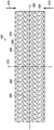
図10は、陰圧下で収縮する接触層140の図であり、ドレッシング110のいくつかの実施形態に関連し得る更なる詳細を示す。図10に示されるように、第1の方向線305及び第2の方向線310は、接触層140の収縮の所望の方向を決定するために使用することができる。例えば、所望の収縮方向は、第2の方向線310に平行であってもよく、第1の方向線305に垂直であってもよい。他の実施形態では、所望の収縮方向は、第1の方向線305に平行であってもよく、第2の方向線310に垂直であってもよい。更に他の実施形態では、所望の収縮方向は、第1の方向線305及び第2の方向線310の双方に対して斜角とすることができる。他の実施形態では、接触層140は、所望の収縮方向を有していなくてもよい。
FIG. 10 is a diagram of the
接触層140が陰圧を受けると、穴205が収縮し得て、これによって、破片を破壊することができる。例えば、穴205の縁部は、破片を破壊することができる切断縁部を形成することができる。いくつかの実施形態では、切断縁部は、穴205の各穴の外周410によって画定されてもよい。例えば陰圧を通気することによって陰圧が除去されると、接触層140は膨張して弛緩位置に戻ることができる。接触層140が収縮位置と弛緩位置との間を循環する場合、接触層140及び保持層の突出部(図示せず)は、破片を更に機械的に破壊し得る。いくつかの実施形態では、陰圧源105によって印加される陰圧は、急速に循環してもよい。例えば、陰圧は、数秒間供給され、その後、数秒間通気され、封止環境において陰圧の脈動を引き起こしてもよい。陰圧の脈動は結節を脈動させ、これによって、破片を更に破壊することができる。組織部位における1つ以上の創傷清拭剤の作用と組み合わせて、接触層140及び穴205がこのように収縮すると、組織部位におけるデブリードマンが有利に増加できるだけでなく、組織部位及び破片の創傷清拭における共作用又は相乗効果を有利に結果としてもたらすことができる。
When the
収縮は、垂直収縮及び側方収縮の双方を指し得る。材料、空隙率、穿孔形状係数、硬度係数、穴205の寸法、及び支線角度は、収縮方向に影響を及ぼすか、又は収縮方向を制御してもよい。例えば、いくつかの実施形態では、空隙率、穿孔形状係数、又は支線角度のうちの1つ以上を用いれば、接触層140は、図6に示されるように、第1の方向線305に垂直な第2の方向線310に沿って収縮することができる。接触層140が組織部位上に配置される場合、接触層140は、第1の方向線305に向かって横方向の力415の方向に収縮してもよい。いくつかの実施形態では、穴205は円形であってもよく、支線角度は約37°であってもよく、空隙率は約54%であってもよく、硬度係数は約5であってもよく、形状係数は約1であってもよく、直径は約5ミリメートルであってもよい。接触層140が約-125mmHgの陰圧を受けた場合、接触層140は、該方向に約11.9Nの横方向の力415を示すことができる。穴205の直径が約20ミリメートルに増加し、空隙率が約52%に変化し、支線角度が約52°に変化し、穿孔形状係数及び硬度係数が同じままである場合、横方向の力は約6.5Nに減少してもよい。
Contraction can refer to both vertical contraction and lateral contraction. The material, porosity, drilling shape factor, hardness factor, hole 205 dimensions, and branch angle may influence or control the shrinkage direction. For example, in some embodiments, using one or more of porosity, perforation shape factor, or branch angle, the
いくつかの実施形態では、穴205の寸法は、穴205を通る微粒子の流れを可能にするように選択されてもよい。いくつかの実施形態では、例えば、穴205の有効径は、組織部位から除去された可溶化された破片の予想されるサイズに基づいて選択されてもよい。大きな破片を許容し小さな破片を遮断するように、寸法を選択することもできる。いくつかの実施例では、破片の一部又は全部は、穴205を通して引き出され、容器115内に収集されてもよい。任意に、穴205のサイズは、ドレッシング110の連続的な適用に伴って異なってもよい。例えば、穴205の寸法は、破片のサイズが減少するにつれて、減少してもよい。穴205のサイズを連続的に減少させることはまた、組織部位の処置中に、破片に対する組織破壊のレベルを微調整するのを援助してもよい。
In some embodiments, the dimensions of the
穴205の寸法はまた、接触層140内及びドレッシング110内の流体移動に影響を及ぼしてもよい。例えば、接触層140は、ドレッシング110内の流体を穴205に向かって導いて、組織部位上の破片の破壊を援助することができる。穴205の寸法が変化すると、流体の除去及び陰圧の印加の双方に関して、流体がドレッシング110を通る移動の仕方が変化してもよい。
The dimensions of the
図7の実施例などのいくつかの実施形態では、破片にかかる応力は、穴205の頂点に集中してもよい。図7の接触層140の好適な特性としては、約66°の支線角度、約55%の空隙率、約5の硬度係数、約1.07の穿孔形状係数、及び約5ミリメートルの有効径を挙げることができる。図7の接触層140が約-125mmHgの陰圧を受ける場合、接触層140の横方向の力415は約13.3Nであり得る。穴205の有効径が10ミリメートルに増加する場合、横方向の力415は約7.5Nに減少してもよい。
In some embodiments, such as the embodiment of FIG. 7, the stress on the debris may be concentrated at the apex of the
いくつかの実施形態では、破片は、ドレッシング交換中に組織部位の表面から除去することができる。例えば、接触層140を除去して、破壊された破片を拭き取ることによって、破片を除去することができる。他の実施形態では、接触層140は、破片が陰圧によって除去され得るように、破片を破壊することができる。
In some embodiments, debris can be removed from the surface of the tissue site during dressing replacement. For example, the debris can be removed by removing the
いくつかの実施形態では、点滴注入療法は、陰圧療法と組み合わせてもよい。例えば、いくつかの実施形態では、溶液源165を接触層140に流体結合してもよい。陰圧療法の期間に続いて、治療システム100は、封止環境に流体を提供するように溶液源165を動作させてもよい。いくつかの実施形態では、溶液源165は、封止環境が通気されている間に流体を提供することができる。他の実施形態では、封止環境は通気されなくてもよく、封止環境における陰圧は、点滴注入流体を溶液源165から封止環境の中へ引き込んでもよい。除去される流体はまた、1つ以上の創傷清拭剤の少なくとも一部、ポリマーの少なくとも一部、並びに創傷清拭マトリックスの増粘剤及び/又は乾燥剤などの任意の更なる構成要素の少なくとも一部、のうちの1つ以上を含んでもよい。
In some embodiments, infusion therapy may be combined with negative pressure therapy. For example, in some embodiments, the
いくつかの実施形態では、溶液源165は、ある体積の流体を封止環境に提供してもよい。いくつかの実施形態では、この流体の体積は、封止環境の体積と同じとすることができる。他の実施形態では、この流体の体積は、封止環境よりも小さくても大きくてもよい。封止環境の中へ溶液を点滴注入することにより、圧力を周囲圧力より高く、例えば約0mmHg~約15mmHg、より具体的には約5mmHgに増加させることができる。いくつかの実施形態では、溶液源165によって提供される流体は、所定の滞留時間の間、封止環境において留まってもよい。いくつかの実施形態では、滞留時間は約5分間であってもよい。他の実施形態では、滞留時間は、所定の時間より長くても短くてもよい。例えば、滞留時間は0であってもよい。
In some embodiments, the
滞留時間の終了時に、点滴注入流体を容器115の中へ引き込むように陰圧源105を動作し、これによって、治療サイクルを完了してもよい。点滴注入流体を陰圧の封止環境から除去すると、陰圧をまた封止環境に供給し、治療の別のサイクルを開始してもよい。
At the end of the dwell time, the
いくつかの実施形態では、例えば治療システム100を使用する、本明細書に記載された方法は、他の組織除去及びデブリードマン技法と併用されてもよい。例えば、更なる機械的及び/又は酵素的デブリードマンプロセスを使用して、例えば、ドレッシング110を配置する前並びに/又は組織部位に陰圧及び/若しくは流体を供給した後に、破片の更なる部分を除去することができる。追加的又は代替的に、例えば、ドレッシング110の配置前並びに/又は組織部位に陰圧及び/若しくは流体を供給した後に、破片の少なくとも一部を除去するために、必要に応じて、鋭利なデブリードマンをも使用することができる。鋭利なデブリードマンとしては、組織部位を創傷清拭する際の外科用メス、鋏、又は他の鋭利な器具の使用を挙げることができるが、これらに限定されない。
In some embodiments, the methods described herein, for example using the
本明細書に記載されたシステム、装置、及び方法によって、著しい利点を得ることができる。例えば、いくつかの実施形態では、治療システム100は、陰圧、点滴注入溶液、又は双方と組み合わせて、機械的移動及び創傷清拭剤を提供して、破片を可溶化、創傷清拭、及び/又は除去することができる。したがって、機械的デブリードマン及び酵素的デブリードマンを組み合わせて提供することができる。いくつかの実施形態では、点滴注入療法及び陰圧療法の周期的適用は、接触層140を浮遊させ、破片に対して位置を変化させてもよい。例えば、陰圧は、陰圧療法サイクル中に封止環境に印加されてもよい。陰圧療法サイクルの終了後、点滴注入療法サイクル中に点滴注入流体を供給することができる。点滴注入流体は、接触層140を破片に対して浮遊させることができる。位置が変化すると、次の陰圧療法サイクル中に接触層140を破片のわずかに異なる部分に係合させ、破片の破壊を援助してもよい。
The systems, devices, and methods described herein can provide significant advantages. For example, in some embodiments, the
追加的又は代替的に、ドレッシング110によって、スラフをより完全に除去することができる。ドレッシング110によれば、陰圧下でのドレッシング110と組織部位、例えば創傷床との接触を改善することによって、スラフ除去を改善することができる。ドレッシング110によって、陰圧療法中に創傷床に形成されたマクロ変形の上部のスラフを剥がすための解決策を得ることができる。 Additional or alternative, the dressing 110 can remove the slough more completely. According to the dressing 110, slough removal can be improved by improving the contact between the dressing 110 and the tissue site, eg, the wound bed, under negative pressure. Dressing 110 provides a solution for stripping the upper slough of macrodeformation formed on the wound bed during negative pressure therapy.
いくつかの例示的な実施形態において示されているが、当業者であれば、本明細書に記載されたシステム、装置、及び方法は、添付の特許請求の範囲内に入るさまざまな変更及び修正が容易に可能であることを認識するであろう。更には、「又は(or)」などの用語を使用するさまざまな代替形態の説明は、文脈によって明らかに必要とされない限り、相互排他性を必要とするものではなく、また、定冠詞「1つの(a)」又は「1つの(an)」は、文脈によって明らかに必要とされない限り、対象を単一の例に限定するものではない。構成要素はまた、販売、製造、組み立て、又は使用の目的のために、さまざまな構成で組み合わせるか、又は削除することもできる。例えば、一部の構成では、製造又は販売のために、ドレッシング110、容器115、又は双方を削除するか、又は他の構成要素から分離することができる。他の例示的な構成では、コントローラ130はまた、他の構成要素とは独立して製造され、構成され、組み立てられ、又は販売されてもよい。追加的又は代替的に、いくつかの実施形態では、保持層145を省略してもよい。例えば、穴205は、接触層140内の凹部であってもよく、組織は、陰圧下で凹部の中へ引き込まれてもよい。いくつかの実施例では、突起を凹部内に配置することができる。
As shown in some exemplary embodiments, those skilled in the art will appreciate various modifications and amendments to the systems, devices, and methods described herein that fall within the scope of the appended claims. Will recognize that is easily possible. Furthermore, explanations of various alternative forms using terms such as "or" do not require mutual exclusivity unless explicitly required by the context, and the definite article "one (a)". ) ”Or“ one (an) ”is not limited to a single example unless explicitly required by the context. The components may also be combined or removed in various configurations for sale, manufacture, assembly, or use. For example, in some configurations, the dressing 110,
添付の特許請求の範囲は、上述の主題の新規かつ発明的な態様を記載するものであるが、特許請求の範囲はまた、具体的には詳細に列挙されていない追加的主題も包含してもよい。例えば、新規かつ発明的な特徴を、当業者には既知であるものから区別するために、必要とされない場合には、特定の特徴、要素、又は態様を、特許請求の範囲から省略することができる。いくつかの実施形態の文脈において説明される特徴、要素、及び態様はまた、添付の特許請求の範囲によって画定される本発明の範囲から逸脱することなく、省略するか、組み合わせるか、又は、同じ目的、均等の目的、若しくは同様の目的を果たす代替的特徴によって置き換えることもできる。 While the appended claims describe novel and inventive aspects of the subject matter described above, the claims also include additional subject matter not specifically listed in detail. May be good. For example, in order to distinguish new and invention features from those known to those skilled in the art, certain features, elements, or embodiments may be omitted from the claims if not required. can. The features, elements, and embodiments described in the context of some embodiments are also omitted, combined, or the same without departing from the scope of the invention as defined by the appended claims. It can also be replaced by a purpose, an equal purpose, or an alternative feature that serves a similar purpose.
Claims (32)
第1のマニホールドを備える接触層であって、前記第1のマニホールドを貫通する複数の穴を有する、接触層と、
複数の突起を有する第2のマニホールドを備える保持層であって、前記突起のうちの少なくとも1つは、前記複数の穴のうちの少なくとも1つの中へ突出する、保持層と、
を備える、ドレッシング。 A dressing for treating tissue sites using negative pressure.
A contact layer comprising a first manifold, the contact layer having a plurality of holes penetrating the first manifold.
A holding layer comprising a second manifold having a plurality of protrusions, wherein at least one of the protrusions protrudes into at least one of the plurality of holes.
The dressing.
請求項1又は2に記載のドレッシング。 The plurality of protrusions are complementary to the plurality of holes.
The dressing according to claim 1 or 2.
請求項1、2、又は3のいずれか一項に記載のドレッシング。 At least some of the plurality of protrusions have tapered ends disposed within the plurality of holes.
The dressing according to any one of claims 1, 2, or 3.
請求項1、又は請求項2~4のいずれか一項に記載のドレッシング。 The first manifold or the second manifold comprises open cell foam.
The dressing according to any one of claims 1 or 2 to 4.
請求項1、又は請求項2~5のいずれか一項に記載のドレッシング。 One or more of the plurality of protrusions has a bumpy outer surface.
The dressing according to any one of claims 1 or 2-5.
請求項1、又は請求項2~6のいずれか一項に記載のドレッシング。 At least one of the plurality of holes has a diameter of 1 to 30 mm and a height of 1 mm to 30 mm.
The dressing according to any one of claims 1 or 2 to 6.
請求項1、又は請求項2~7のいずれか一項に記載のドレッシング。 The retaining layer comprises a foam having an average pore diameter of 10-80 pores per inch.
The dressing according to any one of claims 1 or 2 to 7.
請求項1、又は請求項2~8のいずれか一項に記載のドレッシング。 The contact layer and the holding layer are connected as an integral layer.
The dressing according to any one of claims 1 or 2-8.
請求項1、又は請求項2~9のいずれか一項に記載のドレッシング。 The dressing further comprises a cover layer configured to be disposed adjacent to the holding layer.
The dressing according to any one of claims 1 or 2-9.
請求項1、又は請求項2~10のいずれか一項に記載のドレッシング。 The plurality of holes are configured to crush from a relaxed position to a contracted position in response to negative pressure.
The dressing according to any one of claims 1 or 2 to 10.
請求項1、又は請求項2~11のいずれか一項に記載のドレッシング。 The dressing is configured to be fluid coupled to a negative pressure source.
The dressing according to any one of claims 1 or 2 to 11.
請求項1、又は請求項2~12のいずれか一項に記載のドレッシング。 The dressing is configured to be fluid coupled to a fluid source.
The dressing according to any one of claims 1 or 2 to 12.
組織部位に隣接して配置されるように構成された側面を有するマニホールドと、
前記側面内にある複数の凹部と、
前記凹部のうちの1つ以上内に配置された複数の突起と、備え、
前記複数の凹部は、陰圧に応答して弛緩位置から収縮位置に圧潰するように構成される、
デブリードマン装置。 Debridement device,
A manifold with sides configured to be placed adjacent to the tissue site,
With the plurality of recesses in the side surface,
With a plurality of protrusions arranged in one or more of the recesses,
The plurality of recesses are configured to crush from a relaxed position to a contracted position in response to negative pressure.
Debridement device.
請求項14に記載のデブリードマン装置。 At least some of the plurality of protrusions have tapered ends disposed within the plurality of recesses.
The debridement apparatus according to claim 14.
請求項14又は15に記載のデブリードマン装置。 The manifold comprises open cell foam.
The debridement apparatus according to claim 14 or 15.
請求項14、又は請求項15~16のいずれか一項に記載のデブリードマン装置。 The plurality of protrusions are complementary to the plurality of recesses.
The debridement apparatus according to any one of claims 14 or 15-16.
請求項14、又は請求項15~17のいずれか一項に記載のデブリードマン装置。 At least one of the plurality of recesses has a diameter of 5 to 15 mm.
The debridement apparatus according to any one of claims 14 or 15 to 17.
複数の穴を含む接触層を組織部位に隣接して配置することと、
前記接触層の上に保持層を配置することであって、前記保持層は、前記保持層の表面から延びる複数の突起を備え、前記複数の突起のうちの少なくとも1つは、前記接触層の前記複数の穴のうちの少なくとも1つの中へ突出するように構成される、ことと、
前記組織部位に陰圧を印加することと、を含み、
前記複数の穴は、前記陰圧に応答して弛緩位置から収縮位置に圧潰し、前記組織部位におけるマクロ変形及び前記組織部位からのスラフの受け入れを可能にするように構成される、方法。 Debridement's method, said method
Placing a contact layer containing multiple holes adjacent to the tissue site and
By arranging the holding layer on the contact layer, the holding layer comprises a plurality of protrusions extending from the surface of the holding layer, and at least one of the plurality of protrusions is the contact layer. It is configured to project into at least one of the plurality of holes.
Including applying negative pressure to the tissue site,
The method, wherein the plurality of holes are configured to crush from a relaxed position to a contracted position in response to the negative pressure, allowing macrodeformation at the tissue site and acceptance of sluff from the tissue site.
請求項19に記載の方法。 The holding layer is more compressible than the contact layer.
19. The method of claim 19.
請求項19又は20に記載の方法。 The holding layer or the contact layer comprises an open cell foam.
The method of claim 19 or 20.
請求項19、又は請求項20~21のいずれか一項に記載の方法。 One or more of the plurality of protrusions has a bumpy outer surface.
The method according to any one of claims 19 or 20-21.
請求項19、又は請求項20~22のいずれか一項に記載の方法。 One or more of the plurality of holes has a diameter of 5 to 15 mm.
The method according to any one of claims 19 or 20 to 22.
請求項19、又は請求項20~23のいずれか一項に記載の方法。 The retaining layer comprises a foam having an average pore diameter of 10-80 pores per inch.
The method according to any one of claims 19 or 20 to 23.
請求項19、又は請求項20~24のいずれか一項に記載の方法。 Further comprising placing a cover layer adjacent to the holding layer.
The method according to any one of claims 19 or 20 to 24.
組織部位に隣接して接触層を配置することであって、前記接触層は、
前記組織部位に隣接して配置されるように構成された側面と、
前記側面内にある複数の凹部と、
前記凹部のうちの1つ以上内に配置された複数の突起であって、前記複数の突起のうちの少なくとも1つが、前記接触層の前記複数の凹部のうちの少なくとも1つの中へ突出するように構成される、複数の突起と、
を含む、ことと、
前記組織部位に陰圧を印加することと、
を含み、
前記複数の凹部は、前記陰圧に応答して弛緩位置から収縮位置に圧潰し、前記組織部位におけるマクロ変形及び前記組織部位からのスラフの受け入れを可能にするように構成される、方法。 Debridement's method, said method
By arranging the contact layer adjacent to the tissue site, the contact layer is
Sides configured to be adjacent to the tissue site and
With the plurality of recesses in the side surface,
A plurality of protrusions arranged within one or more of the recesses such that at least one of the plurality of protrusions protrudes into at least one of the plurality of recesses of the contact layer. Consists of multiple protrusions and
Including, and
Applying negative pressure to the tissue site and
Including
A method in which the plurality of recesses are configured to be crushed from a relaxed position to a contracted position in response to the negative pressure, allowing macrodeformation at the tissue site and acceptance of sluff from the tissue site.
請求項26に記載の方法。 The contact layer contains an open cell foam.
The method according to claim 26.
請求項26又は27に記載の方法。 One or more of the plurality of protrusions has a bumpy outer surface.
The method of claim 26 or 27.
請求項26、又は請求項27~28のいずれか一項に記載の方法。 One or more of the plurality of recesses has a diameter of 5 to 15 mm.
The method according to any one of claims 26 or 27 to 28.
請求項26、又は請求項27~29のいずれか一項に記載の方法。 The contact layer comprises a foam having an average pore diameter of 10-80 pores per inch.
The method according to any one of claims 26 or 27-29.
請求項26、又は請求項27~30のいずれか一項に記載の方法。 Further comprising placing a cover layer adjacent to the contact layer.
The method according to any one of claims 26 or 27-30.
システム、装置、及び方法。 Substantially as described herein,
Systems, equipment, and methods.
Applications Claiming Priority (3)
| Application Number | Priority Date | Filing Date | Title |
|---|---|---|---|
| US201862757503P | 2018-11-08 | 2018-11-08 | |
| US62/757,503 | 2018-11-08 | ||
| PCT/US2019/060479 WO2020097467A1 (en) | 2018-11-08 | 2019-11-08 | Dressing with protruding layer allowing for cleansing of wound bed macro deformations |
Publications (2)
| Publication Number | Publication Date |
|---|---|
| JP2022506830A true JP2022506830A (en) | 2022-01-17 |
| JPWO2020097467A5 JPWO2020097467A5 (en) | 2022-11-15 |
Family
ID=69160137
Family Applications (1)
| Application Number | Title | Priority Date | Filing Date |
|---|---|---|---|
| JP2021524439A Pending JP2022506830A (en) | 2018-11-08 | 2019-11-08 | Dressing with a protruding layer that allows cleaning of wound bed macrodeformations |
Country Status (5)
| Country | Link |
|---|---|
| US (2) | US20200146896A1 (en) |
| EP (1) | EP3876886B1 (en) |
| JP (1) | JP2022506830A (en) |
| CN (2) | CN117838434A (en) |
| WO (1) | WO2020097467A1 (en) |
Families Citing this family (12)
| Publication number | Priority date | Publication date | Assignee | Title |
|---|---|---|---|---|
| GB0808376D0 (en) | 2008-05-08 | 2008-06-18 | Bristol Myers Squibb Co | Wound dressing |
| GB201020236D0 (en) | 2010-11-30 | 2011-01-12 | Convatec Technologies Inc | A composition for detecting biofilms on viable tissues |
| CA2819549C (en) | 2010-12-08 | 2019-09-10 | Convatec Technologies Inc. | Wound exudate system accessory |
| JP5965409B2 (en) | 2010-12-08 | 2016-08-03 | コンバテック・テクノロジーズ・インコーポレイテッドConvatec Technologies Inc | Integrated system for assessing wound exudate |
| GB2497406A (en) | 2011-11-29 | 2013-06-12 | Webtec Converting Llc | Dressing with a perforated binder layer |
| WO2014096843A2 (en) | 2012-12-20 | 2014-06-26 | Convatec Technologies Inc. | Processing of chemically modified cellulosic fibres |
| BR112019000284A2 (en) | 2016-07-08 | 2019-04-16 | Convatec Technologies Inc. | fluid collection apparatus |
| EP3481349B1 (en) | 2016-07-08 | 2021-05-05 | ConvaTec Technologies Inc. | Flexible negative pressure system |
| CN109689005B (en) | 2016-07-08 | 2022-03-04 | 康沃特克科技公司 | Fluid flow sensing |
| US11331221B2 (en) | 2019-12-27 | 2022-05-17 | Convatec Limited | Negative pressure wound dressing |
| US11771819B2 (en) | 2019-12-27 | 2023-10-03 | Convatec Limited | Low profile filter devices suitable for use in negative pressure wound therapy systems |
| EP4228575A1 (en) * | 2020-12-01 | 2023-08-23 | KCI Manufacturing Unlimited Company | Contractible dressing manifold with reduced tissue in-growth |
Family Cites Families (8)
| Publication number | Priority date | Publication date | Assignee | Title |
|---|---|---|---|---|
| US8529528B2 (en) * | 2008-12-24 | 2013-09-10 | Kci Licensing, Inc. | Reduced-pressure wound treatment systems and methods employing microstrain-inducing manifolds |
| ES1070675Y (en) * | 2009-05-20 | 2010-01-14 | Canada Juan Marquez | IMPROVED VACUUM TANK APPLICABLE AS POSTOPERATIVE COMPRESSION TREATMENT |
| US9358158B2 (en) * | 2010-03-16 | 2016-06-07 | Kci Licensing, Inc. | Patterned neo-epithelialization dressings, systems, and methods |
| US9352075B2 (en) * | 2010-12-07 | 2016-05-31 | Kci Licensing, Inc. | Wound healing apparatus for promoting granulation and epithelialization at a tissue site |
| US9408941B2 (en) * | 2011-09-20 | 2016-08-09 | Kci Licensing, Inc. | Tissue treatment systems and methods having a non-tactile-stimulus-activated, macroscopically-deforming material |
| CN111419540A (en) * | 2011-12-16 | 2020-07-17 | 凯希特许有限公司 | Releasable medical drape |
| EP3354241B1 (en) * | 2014-05-09 | 2020-12-30 | 3M Innovative Properties Company | Disruptive dressing for use with negative pressure and fluid instillation |
| AU2015255723B2 (en) * | 2014-05-09 | 2019-09-19 | Solventum Intellectual Properties Company | Dressing with contracting layer for linear tissue sites |
-
2019
- 2019-11-08 CN CN202311614633.7A patent/CN117838434A/en active Pending
- 2019-11-08 US US16/678,292 patent/US20200146896A1/en active Granted
- 2019-11-08 EP EP19836102.4A patent/EP3876886B1/en active Active
- 2019-11-08 JP JP2021524439A patent/JP2022506830A/en active Pending
- 2019-11-08 CN CN201980081696.6A patent/CN113543755B/en active Active
- 2019-11-08 WO PCT/US2019/060479 patent/WO2020097467A1/en unknown
-
2023
- 2023-12-12 US US18/537,471 patent/US20240099898A1/en active Pending
Also Published As
| Publication number | Publication date |
|---|---|
| US20240099898A1 (en) | 2024-03-28 |
| CN113543755A (en) | 2021-10-22 |
| EP3876886A1 (en) | 2021-09-15 |
| EP3876886B1 (en) | 2023-09-27 |
| CN113543755B (en) | 2023-12-15 |
| WO2020097467A1 (en) | 2020-05-14 |
| US20200146896A1 (en) | 2020-05-14 |
| CN117838434A (en) | 2024-04-09 |
Similar Documents
| Publication | Publication Date | Title |
|---|---|---|
| JP2022506830A (en) | Dressing with a protruding layer that allows cleaning of wound bed macrodeformations | |
| US11850124B2 (en) | Debridement wound dressings and systems and methods using the same | |
| US11565033B2 (en) | Wound debridement by irrigation with ultrasonically activated microbubbles | |
| JP7090667B2 (en) | Wound cleaning dressing for use with negative pressure and fluid dripping | |
| JP6640114B2 (en) | Disruptive dressing for use with negative pressure and fluid dripping | |
| EP3876885B1 (en) | Wound dressing with semi-rigid support to increase disruption using perforated dressing and negative pressure wound therapy | |
| JP5911066B2 (en) | Re-epithelial wound medical material and system | |
| AU2016382963B2 (en) | System and methods for treatment of wounds with negative pressure and peroxy pyruvic acid | |
| US11878106B2 (en) | System and methods for the treatment of wounds with negative pressure and instillation of peroxide pyruvic acid | |
| JP2023536800A (en) | Tissue interface for tissue debridement |
Legal Events
| Date | Code | Title | Description |
|---|---|---|---|
| A521 | Request for written amendment filed |
Free format text: JAPANESE INTERMEDIATE CODE: A523 Effective date: 20221107 |
|
| A621 | Written request for application examination |
Free format text: JAPANESE INTERMEDIATE CODE: A621 Effective date: 20221107 |
|
| A977 | Report on retrieval |
Free format text: JAPANESE INTERMEDIATE CODE: A971007 Effective date: 20230726 |
|
| A131 | Notification of reasons for refusal |
Free format text: JAPANESE INTERMEDIATE CODE: A131 Effective date: 20230801 |
|
| A521 | Request for written amendment filed |
Free format text: JAPANESE INTERMEDIATE CODE: A523 Effective date: 20231101 |
|
| A711 | Notification of change in applicant |
Free format text: JAPANESE INTERMEDIATE CODE: A711 Effective date: 20240202 |
|
| A02 | Decision of refusal |
Free format text: JAPANESE INTERMEDIATE CODE: A02 Effective date: 20240326 |