JP2022501619A - Systems and methods for laser scattering, deviation and manipulation - Google Patents
Systems and methods for laser scattering, deviation and manipulation Download PDFInfo
- Publication number
- JP2022501619A JP2022501619A JP2021538869A JP2021538869A JP2022501619A JP 2022501619 A JP2022501619 A JP 2022501619A JP 2021538869 A JP2021538869 A JP 2021538869A JP 2021538869 A JP2021538869 A JP 2021538869A JP 2022501619 A JP2022501619 A JP 2022501619A
- Authority
- JP
- Japan
- Prior art keywords
- lenticular
- lenticular sheet
- sheet
- incident
- lenses
- Prior art date
- Legal status (The legal status is an assumption and is not a legal conclusion. Google has not performed a legal analysis and makes no representation as to the accuracy of the status listed.)
- Pending
Links
- 238000000034 method Methods 0.000 title claims abstract description 18
- 239000000463 material Substances 0.000 claims description 20
- 239000011248 coating agent Substances 0.000 claims description 3
- 238000000576 coating method Methods 0.000 claims description 3
- 238000004519 manufacturing process Methods 0.000 claims description 2
- 238000009499 grossing Methods 0.000 claims 1
- 230000008859 change Effects 0.000 abstract description 8
- 239000011159 matrix material Substances 0.000 abstract description 7
- 238000010586 diagram Methods 0.000 description 8
- 238000001514 detection method Methods 0.000 description 6
- 230000011514 reflex Effects 0.000 description 5
- 230000001678 irradiating effect Effects 0.000 description 4
- 230000007246 mechanism Effects 0.000 description 4
- 238000001228 spectrum Methods 0.000 description 4
- XLYOFNOQVPJJNP-UHFFFAOYSA-N water Substances O XLYOFNOQVPJJNP-UHFFFAOYSA-N 0.000 description 4
- 230000000875 corresponding effect Effects 0.000 description 3
- 230000000694 effects Effects 0.000 description 3
- 241000238631 Hexapoda Species 0.000 description 2
- 238000013459 approach Methods 0.000 description 2
- 239000003086 colorant Substances 0.000 description 2
- 230000000295 complement effect Effects 0.000 description 2
- 238000002474 experimental method Methods 0.000 description 2
- 230000003287 optical effect Effects 0.000 description 2
- 230000005855 radiation Effects 0.000 description 2
- 238000001429 visible spectrum Methods 0.000 description 2
- 229920008790 Amorphous Polyethylene terephthalate Polymers 0.000 description 1
- 241000271566 Aves Species 0.000 description 1
- 241000288673 Chiroptera Species 0.000 description 1
- 241000984642 Cura Species 0.000 description 1
- 206010034972 Photosensitivity reaction Diseases 0.000 description 1
- 239000004743 Polypropylene Substances 0.000 description 1
- 239000004793 Polystyrene Substances 0.000 description 1
- 241000283984 Rodentia Species 0.000 description 1
- NIXOWILDQLNWCW-UHFFFAOYSA-N acrylic acid group Chemical group C(C=C)(=O)O NIXOWILDQLNWCW-UHFFFAOYSA-N 0.000 description 1
- 230000003321 amplification Effects 0.000 description 1
- 238000004458 analytical method Methods 0.000 description 1
- 230000009286 beneficial effect Effects 0.000 description 1
- 239000002131 composite material Substances 0.000 description 1
- 230000002596 correlated effect Effects 0.000 description 1
- 238000009792 diffusion process Methods 0.000 description 1
- 239000000428 dust Substances 0.000 description 1
- 238000005516 engineering process Methods 0.000 description 1
- 238000001125 extrusion Methods 0.000 description 1
- 239000011521 glass Substances 0.000 description 1
- 230000001788 irregular Effects 0.000 description 1
- 238000003698 laser cutting Methods 0.000 description 1
- 238000001459 lithography Methods 0.000 description 1
- 239000002184 metal Substances 0.000 description 1
- 239000000203 mixture Substances 0.000 description 1
- 238000012986 modification Methods 0.000 description 1
- 230000004048 modification Effects 0.000 description 1
- 230000004297 night vision Effects 0.000 description 1
- 238000003199 nucleic acid amplification method Methods 0.000 description 1
- 230000000737 periodic effect Effects 0.000 description 1
- 230000036211 photosensitivity Effects 0.000 description 1
- 239000004033 plastic Substances 0.000 description 1
- 239000002985 plastic film Substances 0.000 description 1
- 229920000515 polycarbonate Polymers 0.000 description 1
- 239000004417 polycarbonate Substances 0.000 description 1
- 229920005644 polyethylene terephthalate glycol copolymer Polymers 0.000 description 1
- -1 polypropylene Polymers 0.000 description 1
- 229920001155 polypropylene Polymers 0.000 description 1
- 229920002223 polystyrene Polymers 0.000 description 1
- 229920000915 polyvinyl chloride Polymers 0.000 description 1
- 239000004800 polyvinyl chloride Substances 0.000 description 1
- 230000001681 protective effect Effects 0.000 description 1
- 230000009467 reduction Effects 0.000 description 1
- 230000004044 response Effects 0.000 description 1
- 238000005096 rolling process Methods 0.000 description 1
- 238000006467 substitution reaction Methods 0.000 description 1
- 230000001960 triggered effect Effects 0.000 description 1
Images


Classifications
-
- G—PHYSICS
- G01—MEASURING; TESTING
- G01S—RADIO DIRECTION-FINDING; RADIO NAVIGATION; DETERMINING DISTANCE OR VELOCITY BY USE OF RADIO WAVES; LOCATING OR PRESENCE-DETECTING BY USE OF THE REFLECTION OR RERADIATION OF RADIO WAVES; ANALOGOUS ARRANGEMENTS USING OTHER WAVES
- G01S7/00—Details of systems according to groups G01S13/00, G01S15/00, G01S17/00
- G01S7/48—Details of systems according to groups G01S13/00, G01S15/00, G01S17/00 of systems according to group G01S17/00
- G01S7/481—Constructional features, e.g. arrangements of optical elements
- G01S7/4814—Constructional features, e.g. arrangements of optical elements of transmitters alone
-
- F—MECHANICAL ENGINEERING; LIGHTING; HEATING; WEAPONS; BLASTING
- F41—WEAPONS
- F41H—ARMOUR; ARMOURED TURRETS; ARMOURED OR ARMED VEHICLES; MEANS OF ATTACK OR DEFENCE, e.g. CAMOUFLAGE, IN GENERAL
- F41H3/00—Camouflage, i.e. means or methods for concealment or disguise
-
- G—PHYSICS
- G01—MEASURING; TESTING
- G01S—RADIO DIRECTION-FINDING; RADIO NAVIGATION; DETERMINING DISTANCE OR VELOCITY BY USE OF RADIO WAVES; LOCATING OR PRESENCE-DETECTING BY USE OF THE REFLECTION OR RERADIATION OF RADIO WAVES; ANALOGOUS ARRANGEMENTS USING OTHER WAVES
- G01S7/00—Details of systems according to groups G01S13/00, G01S15/00, G01S17/00
- G01S7/48—Details of systems according to groups G01S13/00, G01S15/00, G01S17/00 of systems according to group G01S17/00
- G01S7/481—Constructional features, e.g. arrangements of optical elements
- G01S7/4817—Constructional features, e.g. arrangements of optical elements relating to scanning
-
- G—PHYSICS
- G02—OPTICS
- G02B—OPTICAL ELEMENTS, SYSTEMS OR APPARATUS
- G02B1/00—Optical elements characterised by the material of which they are made; Optical coatings for optical elements
- G02B1/10—Optical coatings produced by application to, or surface treatment of, optical elements
- G02B1/11—Anti-reflection coatings
-
- G—PHYSICS
- G02—OPTICS
- G02B—OPTICAL ELEMENTS, SYSTEMS OR APPARATUS
- G02B27/00—Optical systems or apparatus not provided for by any of the groups G02B1/00 - G02B26/00, G02B30/00
- G02B27/09—Beam shaping, e.g. changing the cross-sectional area, not otherwise provided for
- G02B27/0905—Dividing and/or superposing multiple light beams
-
- G—PHYSICS
- G02—OPTICS
- G02B—OPTICAL ELEMENTS, SYSTEMS OR APPARATUS
- G02B27/00—Optical systems or apparatus not provided for by any of the groups G02B1/00 - G02B26/00, G02B30/00
- G02B27/09—Beam shaping, e.g. changing the cross-sectional area, not otherwise provided for
- G02B27/0938—Using specific optical elements
- G02B27/0944—Diffractive optical elements, e.g. gratings, holograms
-
- G—PHYSICS
- G02—OPTICS
- G02B—OPTICAL ELEMENTS, SYSTEMS OR APPARATUS
- G02B27/00—Optical systems or apparatus not provided for by any of the groups G02B1/00 - G02B26/00, G02B30/00
- G02B27/09—Beam shaping, e.g. changing the cross-sectional area, not otherwise provided for
- G02B27/0938—Using specific optical elements
- G02B27/095—Refractive optical elements
- G02B27/0955—Lenses
- G02B27/0961—Lens arrays
-
- G—PHYSICS
- G02—OPTICS
- G02B—OPTICAL ELEMENTS, SYSTEMS OR APPARATUS
- G02B27/00—Optical systems or apparatus not provided for by any of the groups G02B1/00 - G02B26/00, G02B30/00
- G02B27/09—Beam shaping, e.g. changing the cross-sectional area, not otherwise provided for
- G02B27/0938—Using specific optical elements
- G02B27/095—Refractive optical elements
- G02B27/0955—Lenses
- G02B27/0966—Cylindrical lenses
-
- G—PHYSICS
- G02—OPTICS
- G02B—OPTICAL ELEMENTS, SYSTEMS OR APPARATUS
- G02B3/00—Simple or compound lenses
- G02B3/0087—Simple or compound lenses with index gradient
-
- G—PHYSICS
- G02—OPTICS
- G02B—OPTICAL ELEMENTS, SYSTEMS OR APPARATUS
- G02B3/00—Simple or compound lenses
- G02B3/02—Simple or compound lenses with non-spherical faces
- G02B3/06—Simple or compound lenses with non-spherical faces with cylindrical or toric faces
-
- G—PHYSICS
- G02—OPTICS
- G02B—OPTICAL ELEMENTS, SYSTEMS OR APPARATUS
- G02B5/00—Optical elements other than lenses
- G02B5/18—Diffraction gratings
-
- G—PHYSICS
- G02—OPTICS
- G02B—OPTICAL ELEMENTS, SYSTEMS OR APPARATUS
- G02B5/00—Optical elements other than lenses
- G02B5/18—Diffraction gratings
- G02B5/1866—Transmission gratings characterised by their structure, e.g. step profile, contours of substrate or grooves, pitch variations, materials
-
- G—PHYSICS
- G03—PHOTOGRAPHY; CINEMATOGRAPHY; ANALOGOUS TECHNIQUES USING WAVES OTHER THAN OPTICAL WAVES; ELECTROGRAPHY; HOLOGRAPHY
- G03B—APPARATUS OR ARRANGEMENTS FOR TAKING PHOTOGRAPHS OR FOR PROJECTING OR VIEWING THEM; APPARATUS OR ARRANGEMENTS EMPLOYING ANALOGOUS TECHNIQUES USING WAVES OTHER THAN OPTICAL WAVES; ACCESSORIES THEREFOR
- G03B21/00—Projectors or projection-type viewers; Accessories therefor
- G03B21/54—Accessories
- G03B21/56—Projection screens
- G03B21/60—Projection screens characterised by the nature of the surface
- G03B21/602—Lenticular screens
-
- G—PHYSICS
- G03—PHOTOGRAPHY; CINEMATOGRAPHY; ANALOGOUS TECHNIQUES USING WAVES OTHER THAN OPTICAL WAVES; ELECTROGRAPHY; HOLOGRAPHY
- G03B—APPARATUS OR ARRANGEMENTS FOR TAKING PHOTOGRAPHS OR FOR PROJECTING OR VIEWING THEM; APPARATUS OR ARRANGEMENTS EMPLOYING ANALOGOUS TECHNIQUES USING WAVES OTHER THAN OPTICAL WAVES; ACCESSORIES THEREFOR
- G03B21/00—Projectors or projection-type viewers; Accessories therefor
- G03B21/54—Accessories
- G03B21/56—Projection screens
- G03B21/60—Projection screens characterised by the nature of the surface
- G03B21/604—Polarised screens
-
- H—ELECTRICITY
- H04—ELECTRIC COMMUNICATION TECHNIQUE
- H04N—PICTORIAL COMMUNICATION, e.g. TELEVISION
- H04N13/00—Stereoscopic video systems; Multi-view video systems; Details thereof
- H04N13/30—Image reproducers
- H04N13/363—Image reproducers using image projection screens
-
- G—PHYSICS
- G02—OPTICS
- G02B—OPTICAL ELEMENTS, SYSTEMS OR APPARATUS
- G02B3/00—Simple or compound lenses
- G02B3/0006—Arrays
- G02B3/0037—Arrays characterized by the distribution or form of lenses
- G02B3/005—Arrays characterized by the distribution or form of lenses arranged along a single direction only, e.g. lenticular sheets
-
- G—PHYSICS
- G02—OPTICS
- G02B—OPTICAL ELEMENTS, SYSTEMS OR APPARATUS
- G02B3/00—Simple or compound lenses
- G02B3/0006—Arrays
- G02B3/0037—Arrays characterized by the distribution or form of lenses
- G02B3/0062—Stacked lens arrays, i.e. refractive surfaces arranged in at least two planes, without structurally separate optical elements in-between
Abstract
レーザビームを散乱または偏位させるためのシステムおよび方法が提供される。レンチキュラシートおよびレンチキュラシートにレーザビームを投射するレーザ源を活用するシステムは、レーザコーンなどの形状を生成する。レンチキュラシートに関するレーザ源の微調節が、改善された光検出および測距(ライダ)システムを提供するレーザコーンのサイズおよび形状を変更し得る。レーザビームの経路に追加される回折格子が線の行列のレーザパターンを生成させ、同じく改善を提供する。レーザビームを偏位させてレーザ誘導発射体および/またはレーザ獲得から軍事資産を保護するために、多重レンチキュラシート間の干渉が使用され得る。Systems and methods for scattering or deviating a laser beam are provided. A system that utilizes a lenticular sheet and a laser source that projects a laser beam onto the lenticular sheet produces shapes such as laser cones. Tweaking of the laser source with respect to the lenticular sheet can change the size and shape of the laser cone to provide an improved photodetection and ranging (rider) system. A diffraction grating added to the path of the laser beam produces a laser pattern of a matrix of lines, which also provides an improvement. Interference between multiple lenticula sheets can be used to deflect the laser beam and protect military assets from laser-guided projectiles and / or laser acquisition.
Description
本発明は、一般に光線の操作に関し、より詳細にはレーザ散乱、偏位および操作のためのシステムおよび方法に関する。 The present invention relates generally to the manipulation of light rays, and more particularly to systems and methods for laser scattering, deviation and manipulation.
レーザ(laser)は「light amplification by stimulated emission of radiation(放射の誘導放出による光増幅)」を表す。レーザは、それが空間的にも時間的にもコヒーレントに光を放出するという点で他の光源と異なる。空間コヒーレンスは、レーザが狭いスポットに集光されることを許容して、レーザ切断およびリソグラフィなどの応用を可能にする。空間コヒーレンスは、レーザビームが遠距離にわたって細い状態を保つこと(コリメーション)も許容して、レーザポインタなどの応用を可能にする。レーザは高時間コヒーレンスも有することができ、それらが超狭スペクトルの光を放出するのを許容する、すなわち、それらは単色の光を放出できる。時間コヒーレンスは、1フェムト秒と同様に短い光のパルスを生成するために使用できる。 Laser stands for "light amplification by stimulated emission of radiation". Lasers differ from other light sources in that they emit light coherently both spatially and temporally. Spatial coherence allows the laser to be focused on a narrow spot, allowing applications such as laser cutting and lithography. Spatial coherence also allows the laser beam to remain thin over long distances (collimation), enabling applications such as laser pointers. Lasers can also have high time coherence, allowing them to emit ultra-narrow spectrum light, i.e. they can emit monochromatic light. Time coherence can be used to generate short pulses of light as well as 1 femtosecond.
レンチキュラシートは半透明プラスチックシートであり、片側に一連の垂直に配列された、レンチキュールと呼ばれる平凸円柱レンズおよび他の側に平面を有し、異形かつ精密押出しによって製作されている。レンチキュールは、2D画像を種々の錯視へ変換するのに役立ち、レンチキュラシートの向きが変えられると観察者がレンチキュラ特殊効果を見得る。レンチキュラシートは、アクリル、APET、PETG、ポリカーボネート、ポリプロピレン、PVCまたはポリスチレンから製作され得る。それらの異種材料の各々が異なるレベルの温度およびUV光感応性を有する。 The lenticular sheet is a translucent plastic sheet, with a series of vertically arranged plano-convex cylindrical lenses called lenticulars on one side and a flat surface on the other side, made by irregular and precision extrusion. Lenticulars help transform 2D images into various optical illusions, and observers can see lenticular special effects when the lenticular sheet is reoriented. Lenticular sheets can be made from acrylic, APET, PETG, polycarbonate, polypropylene, PVC or polystyrene. Each of these dissimilar materials has different levels of temperature and UV photosensitivity.
レンチキュラシートの重要な特性がレンズの密度である。レンズの密度はインチ当たりのレンズまたはインチ当たりのレンチキュール(LPI)として表される。レンチキュラシートの厚さは、常にではないが通常はLPIに逆相関しており、LPIが低いほど、レンチキュラシートは厚くなる。レンチキュラシートの別の重要な特性が視角である。レンチキュラシートの視角は、レンチキュラ画像が明瞭に見られ得るv形領域である。 An important property of the lenticular sheet is the density of the lens. Lens density is expressed as lens per inch or wrench curl (LPI) per inch. The thickness of the lenticular sheet is usually, but not always, inversely correlated with the LPI, the lower the LPI, the thicker the lenticular sheet. Another important property of the lenticular sheet is the viewing angle. The viewing angle of the lenticular sheet is the v-shaped region where the lenticular image can be clearly seen.
回折格子は、非常に近い平行線が刻線されたガラス、プラスチックまたは金属の板であり、光の回折および干渉によってスペクトルを生成する。回折格子は、光を異なる方向に進行する幾つかのビームへ分割および回折する周期構造を持つ光学部品である。現れる呈色は構造的呈色の形態である。ビームの方向は格子の間隔および光の波長に依存し、その結果格子は分散素子として作用する。ホログラフィック回折格子は非常に効率的なエンボスホログラフィック光学素子(HOE)である。回折格子は、種々のガス入り管および他の光源からのスペクトルの直視および解析のために使用される。パターンサイズが、インチ当たりの線またはmm(ミリメートル)当たりの線の数で測定されており、回折格子の重要な特性である。一部の回折格子はインチ当たり13,500本の線を有する。単軸回折格子は複数の平行線を有する。二軸回折格子は、第1の複数の平行線および第1の複数の平行線に垂直な第2の複数の平行線を有する。回折格子は、光および色の研究に関連する実験で使用される。 A diffraction grating is a glass, plastic, or metal plate with very close parallel lines engraved on it, which produces a spectrum by diffraction and interference of light. A diffraction grating is an optical component having a periodic structure that divides and diffracts light into several beams traveling in different directions. The coloration that appears is a form of structural coloration. The direction of the beam depends on the spacing of the grid and the wavelength of the light, so that the grid acts as a dispersive element. Holographic gratings are highly efficient embossed holographic optics (HOEs). Diffraction gratings are used for direct viewing and analysis of spectra from various gas-filled tubes and other light sources. The pattern size is measured by the number of lines per inch or mm (millimeters) and is an important property of the grating. Some gratings have 13,500 lines per inch. The uniaxial diffraction grating has a plurality of parallel lines. The biaxial diffraction grating has a first plurality of parallel lines and a second plurality of parallel lines perpendicular to the first plurality of parallel lines. Diffraction gratings are used in experiments related to light and color studies.
ライダ(光検出および測距)はレーザベースのリモートセンシング技術である。ライダの背後にある理論は、表面にレーザビームを向けて、レーザが物体に当たるのに要する時間を測定することである。典型的にレーザ源にあるまたはその近くの光学センサが、これらの当たりを検出する。次いでレーザが光の速さで進行することを知ることで、光の速さに検出時間を掛け、次いで2で割ることによって、検出表面までの距離を決定できる。ライダシステムは、このように少なくとも1つのレーザ源および少なくとも1つのセンサを活用する。ライダシステムは、地上設置、水中設置、宇宙設置、または飛行機、車もしくはUAV(無人航空機)に搭載され得る。 Riders (photodetection and ranging) are laser-based remote sensing technologies. The theory behind the rider is to direct the laser beam at the surface and measure the time it takes for the laser to hit an object. An optical sensor, typically at or near the laser source, detects these hits. By knowing that the laser then travels at the speed of light, the distance to the detection surface can be determined by multiplying the speed of light by the detection time and then dividing by two. The rider system thus utilizes at least one laser source and at least one sensor. The rider system can be mounted on the ground, underwater, in space, or on an airplane, car or UAV (unmanned aerial vehicle).
本開示の一態様において、レーザビームを転向させるためのシステムが提供される。本システムは、ドットとして投射する複数の光線を含む入射レーザビームを放出するレーザ源と、複数の平行な長手方向のレンチキュラレンズを含むレンズ側およびレンズ側と反対の平滑側を有するレンチキュラシートとを備える。レーザ源は、入射レーザビームが複数の平行な長手方向のレンチキュラレンズの少なくとも1つに当たるようにレンチキュラシートのレンズ側の方へ向けられる。入射レーザビームの複数の光線の第1の部分が屈折によって転向されて、第1の形状の屈折ビームを形成する。入射レーザビームの複数の光線の第2の部分が複数の平行な長手方向のレンチキュラレンズの少なくとも1つの表面によって反射されて、第2の特定形状の反射ビームを形成する。 In one aspect of the present disclosure, a system for divert a laser beam is provided. The system comprises a laser source that emits an incident laser beam containing multiple rays projected as dots, a lens side that includes multiple parallel longitudinal lenticular lenses, and a lenticular sheet that has a smooth side opposite to the lens side. Be prepared. The laser source is directed towards the lens side of the lenticular sheet so that the incident laser beam hits at least one of a plurality of parallel longitudinal lenticular lenses. The first portion of the plurality of rays of the incident laser beam is turned by refraction to form a refracted beam of first shape. The second portion of the plurality of rays of the incident laser beam is reflected by at least one surface of the plurality of parallel longitudinal lenticular lenses to form a second particular shaped reflected beam.
一実施形態において、レーザ源は、第1の入射レーザビームが複数の平行な長手方向のレンチキュラレンズの少なくとも1つに垂直に当たるように向けられ、屈折によって転向される入射レーザビームの第1の部分は入射レーザビームの複数の光線の大半を表し、第1の特定形状の屈折ビームは、直線として投射される三角面ビームの形態である。 In one embodiment, the laser source is a first portion of the incident laser beam that is directed so that the first incident laser beam hits at least one of a plurality of parallel longitudinal lenticular lenses perpendicularly and is refracted. Represents most of the plurality of rays of the incident laser beam, and the refraction beam of the first specific shape is in the form of a triangular surface beam projected as a straight line.
一実施形態において、レンチキュラシートは、複数の平行な長手方向のレンズが水平に配向されるような直立位置に設置され、三角面ビームは垂直に配向され、投射直線は垂直である。 In one embodiment, the lenticular sheet is placed in an upright position such that a plurality of parallel longitudinal lenses are horizontally oriented, the triangular beam is vertically oriented, and the projection line is vertical.
一実施形態において、レンチキュラシートは、複数の平行な長手方向のレンチキュラレンズが垂直に配向されるような直立位置に設置され、三角面ビームは水平に配向され、投射直線は水平である。 In one embodiment, the lenticular sheet is placed in an upright position such that a plurality of parallel longitudinal lenticular lenses are vertically oriented, the triangular beam is horizontally oriented, and the projection line is horizontal.
一実施形態において、レーザ源は、屈折によって転向される第1の入射レーザビームの複数の光線の第1の部分が第1の入射レーザビームの複数の光線の大半を表し、第1の入射レーザビームが、複数の平行な長手方向のレンチキュラレンズの少なくとも1つを通る水平面と同じ面にあり、特定形状の屈折ビームが、弧として投射される曲面の形態であるように、入射レーザビームが複数の平行な長手方向のレンチキュラレンズの少なくとも1つに垂直方向に入射角をなして当たるように、向けられる。 In one embodiment, the laser source is a first incident laser in which the first portion of the plurality of rays of the first incident laser beam turned by refraction represents the majority of the plurality of rays of the first incident laser beam. Multiple incident laser beams, such that the beam is on the same plane as the horizontal plane through at least one of multiple parallel longitudinal lenticular lenses and the refracted beam of a particular shape is in the form of a curved surface projected as an arc. It is oriented so that it hits at least one of the parallel longitudinal lenticular lenses at a vertical angle of incidence.
一実施形態において、レーザ源は、第1および第2の部分が、円に投射するコーンを共に形成するように、第1の入射レーザビームが複数の平行な長手方向のレンチキュラレンズの少なくとも1つに垂直方向から入射角をなして当たるように、向けられる。 In one embodiment, the laser source is at least one of a plurality of parallel longitudinal lenticular lenses with a first incident laser beam such that the first and second portions together form a cone that projects onto a circle. It is directed so that it hits at an incident angle from the vertical direction.
一実施形態において、レンチキュラシートのレンズ側は、複数の長手方向のレンチキュラレンズの少なくとも1つの表面によって反射される複数の光線の第2の部分が入射レーザビームの複数の光線の全てを含むような反射材料で被覆される。 In one embodiment, the lens side of the lenticular sheet is such that the second portion of the plurality of rays reflected by at least one surface of the plurality of longitudinal lenticular lenses contains all of the plurality of rays of the incident laser beam. Covered with reflective material.
一実施形態において、複数の長手方向のレンチキュラレンズの少なくとも1つの表面によって反射される入射レーザビームの複数の光線の第2の部分を減少させるためにレンチキュラシートのレンズ側および平滑側の少なくとも1つに反射防止層またはコーティングが設けられる。 In one embodiment, at least one of the lens side and the smooth side of the lenticular sheet to reduce the second portion of the plurality of rays of the incident laser beam reflected by at least one surface of the plurality of longitudinal lenticular lenses. Is provided with an antireflection layer or coating.
一実施形態において、本システムは、入射レーザビームがレンチキュラシートを通過する前に回折格子を通過するようにレーザ源とレンチキュラシートとの間に位置付けられる少なくとも1つの回折格子を更に備える。 In one embodiment, the system further comprises at least one diffraction grating that is positioned between the laser source and the lenticular sheet such that the incident laser beam passes through the diffraction grating before passing through the lenticular sheet.
一実施形態において、本システムは、入射レーザビームがレンチキュラシートを通過した後に回折格子を通過するようにレンチキュラシートの後に位置付けられる少なくとも1つの回折格子を更に備える。 In one embodiment, the system further comprises at least one diffraction grating that is positioned after the lenticular sheet so that the incident laser beam passes through the lenticular sheet and then through the diffraction grating.
一実施形態において、レンチキュラシートは、複数の平行な長手方向のレンズが水平に配向されるような直立位置に設置され、かつ少なくとも1つの回折格子は、その複数の線が垂直に配向されるように配向される少なくとも1つの線形回折格子を含む。 In one embodiment, the lenticula sheet is placed in an upright position such that a plurality of parallel longitudinal lenses are horizontally oriented, and at least one diffraction grating is such that the plurality of lines are vertically oriented. Includes at least one linear diffraction grating oriented in.
一実施形態において、レンチキュラシートは、複数の平行な長手方向のレンズが水平面に角度をなして配向されるような直立位置に設置され、少なくとも1つの回折格子は、その複数の線が垂直に配向されるように配向される少なくとも1つの線形回折格子を含む。 In one embodiment, the lenticula sheet is placed in an upright position such that a plurality of parallel longitudinal lenses are oriented at an angle to a horizontal plane, and at least one diffraction grating has the plurality of lines oriented vertically. Includes at least one linear diffraction grating oriented to be.
一実施形態において、レンチキュラシートは、複数の平行な長手方向のレンズが水平に配向されるような直立位置に設置され、少なくとも1つの回折格子は、その第1の複数の線が垂直に配向され、その第2の複数の線が水平に配向されるように配向される少なくとも1つの二軸回折格子を含む。 In one embodiment, the lenticula sheet is placed in an upright position such that a plurality of parallel longitudinal lenses are horizontally oriented, and at least one diffraction grating is vertically oriented with its first plurality of lines. , Includes at least one biaxial diffraction grating in which the second plurality of lines are oriented so that they are oriented horizontally.
一実施形態において、レンチキュラシートは、複数の平行な長手方向のレンズが水平面に角度をなして配向されるような直立位置に設置され、少なくとも1つの回折格子は、その第1の複数の線が垂直に配向され、その第2の複数の線が水平に配向されるように配向される少なくとも1つの二軸回折格子を含む。 In one embodiment, the lenticula sheet is placed in an upright position such that a plurality of parallel longitudinal lenses are oriented at an angle to a horizontal plane, and at least one diffraction grating has its first plurality of lines. Includes at least one biaxial diffraction grating that is vertically oriented and its second plurality of lines oriented horizontally.
本開示の別の態様において、2つのレーザビームを操作してコーンを形成するためのシステムが提供される。本システムは、ドットに投射する複数の光線から構成される第1の入射ビームを生成する第1のレーザ源と、ドットに投射する複数の光線から構成される第2の入射ビームを生成する第2のレーザ源と、複数の平行な長手方向のレンチキュラレンズを含む第1のレンズ側および第1のレンズ側と反対の複数の平行な長手方向のレンチキュラレンズを含む第2のレンズ側を有する両面レンチキュラシートとを備える。第1のレーザ源は、第1の入射ビーム光線の大半が反射されて第1の曲面を形成するような入射角で第1の入射ビームが複数の平行な長手方向のレンチキュラレンズの1つに当たるようにレンチキュラシートの第1の側の方へ向けられる。第2のレーザ源は、第2の入射ビーム光線の大半が屈折されて第2の曲面を形成するような第1のレーザ源と同じ入射角で第2の入射ビームが複数の平行な長手方向のレンチキュラレンズの1つの反対側に当たるようにレンチキュラシートの第2の側の方へ向けられる。第1および第2の曲面は、円として投射されるコーンを共に形成する。 In another aspect of the present disclosure, a system for manipulating two laser beams to form a cone is provided. The system produces a first laser source that produces a first incident beam composed of multiple rays projected onto a dot and a second incident beam composed of multiple rays projected onto a dot. Double-sided with two laser sources and a first lens side containing multiple parallel longitudinal wrenchular lenses and a second lens side containing multiple parallel longitudinal wrenchular lenses opposite the first lens side Equipped with a lenticular sheet. The first laser source is one of a plurality of parallel longitudinal lenticular lenses with the first incident beam at an incident angle such that most of the first incident beam beam is reflected to form the first curved surface. It is turned toward the first side of the lenticular sheet. The second laser source has a plurality of parallel longitudinal directions of the second incident beam at the same angle of incidence as the first laser source such that most of the second incident beam beam is refracted to form a second curved surface. Pointed towards the second side of the lenticular sheet so that it hits the other side of one of the lenticular lenses. The first and second curved surfaces together form a cone projected as a circle.
一実施形態において、両面レンチキュラシートは、レンズ側および平滑側を各々有する第1および第2の片面レンチキュラシートを含み、かつ第1および第2の片面レンチキュラシートは、それらのそれぞれの平滑側において背中合わせに位置付けられる。 In one embodiment, the double-sided lenticular sheet comprises a first and second single-sided lenticular sheet having a lens side and a smooth side, respectively, and the first and second single-sided lenticular sheets are back-to-back on their respective smooth sides. Positioned in.
一実施形態において、本システムは、第1および第2の片面レンチキュラシートのそれぞれの平滑側間に設けられる明るい不透明材料のシートを更に備える。 In one embodiment, the system further comprises a sheet of bright opaque material provided between the smooth sides of each of the first and second single-sided lenticular sheets.
一実施形態において、明るい不透明材料のシートは両面ミラーを含む。 In one embodiment, the sheet of bright opaque material comprises a double-sided mirror.
一実施形態において、第1のレンズ側および第2のレンズ側は反射材料で被覆または製作される。 In one embodiment, the first lens side and the second lens side are coated or made of a reflective material.
一実施形態において、第1および第2の片面レンチキュラシートの平滑側は反射材料で被覆される。 In one embodiment, the smooth side of the first and second single-sided lenticular sheets is coated with a reflective material.
本開示の更に別の態様において、2つのレーザビームを操作してコーンを形成するためのシステムが提供される。本システムは、ドットに投射する複数の光線から構成される第1の入射ビームを生成する第1のレーザ源と、ドットに投射する複数の光線から構成される第2の入射ビームを生成する第2のレーザ源と、複数の平行な長手方向のレンチキュラレンズを含む第1のレンズ側および第1のレンズ側と反対の複数の平行な長手方向のレンチキュラレンズを含む第2のレンズ側を有するレンチキュラシートとを備える。第1のレーザ源は、第1の入射ビーム光線が屈折および反射されて第1のコーンを形成するような第1の入射角で第1の入射ビームが複数の平行な長手方向のレンチキュラレンズの1つに当たるようにレンチキュラシートの第1の側の方へ向けられる。第2のレーザ源は、第2の入射ビーム光線が屈折および反射されて、第1のコーンより大きくかつそれと同軸の第2のコーンを形成するような第1の入射角より大きい入射角で第2の入射ビームが複数の平行な長手方向のレンチキュラレンズの1つの反対側に当たるようにレンチキュラシートの第2の側の方へ向けられる。 In yet another aspect of the present disclosure, a system for manipulating two laser beams to form a cone is provided. The system produces a first laser source that produces a first incident beam composed of multiple rays projected onto a dot and a second incident beam composed of multiple rays projected onto a dot. A lenticular with two laser sources and a first lens side containing multiple parallel longitudinal lenticular lenses and a second lens side containing multiple parallel longitudinal lenticular lenses opposite the first lens side. Equipped with a seat. The first laser source is of a plurality of parallel longitudinal lenticular lenses with a first incident beam at a first angle of incidence such that the first incident beam beam is refracted and reflected to form a first cone. Pointed towards the first side of the lenticular sheet so that it hits one. The second laser source is at an incident angle larger than the first incident angle such that the second incident beam beam is refracted and reflected to form a second cone that is larger than and parallel to the first cone. The incident beam of 2 is directed towards the second side of the lenticular sheet so that it hits the opposite side of one of the multiple parallel longitudinal lenticular lenses.
一実施形態において、第1および第2のビームは、第1のコーンの頂点と第2のコーンの頂点との間に距離があるように、それらが複数の平行な長手方向のレンチキュラレンズの1つに当たるときに離隔される。 In one embodiment, the first and second beams are one of a plurality of parallel longitudinal lenticular lenses such that there is a distance between the apex of the first cone and the apex of the second cone. You will be separated when you hit one.
本開示の更に別の態様において、光検出および測距(ライダ)システムを使用して少なくとも1つの物体を検出する方法が提供される。本方法は、反射光線の第1のハーフコーンを生成するために両面レンチキュラシートの第1のレンズ側へ第1の角度で第1の入射レーザビームを投射するステップと、反射光線の第1のハーフコーンと共に反射光線のフルコーンを形成する反射光線の第2のハーフコーンを生成するために両面レンチキュラシートの第2のレンズ側へ第2の角度で第2の入射レーザビームを投射するステップと、ライダシステムの少なくとも1つのセンサによって、少なくとも1つの物体がフルコーンの反射光線のいずれか1つを横切るときに少なくとも1つの物体から反射される信号を検出するステップとを含む。 In yet another aspect of the present disclosure, a method of detecting at least one object using a photodetection and ranging (rider) system is provided. The method comprises projecting a first incident laser beam at a first angle onto the first lens side of a double-sided lenticula sheet to generate a first half-cone of reflected light, and a first of the reflected light. A step of projecting a second incident laser beam at a second angle onto the second lens side of the double-sided lenticula sheet to create a second half-cone of reflected light that forms a full cone of reflected light with the half-cone. The rider system includes at least one sensor to detect the signal reflected from at least one object as it crosses any one of the reflected rays of a full cone.
一実施形態において、本方法は、第1のハーフコーンおよび第2のハーフコーンのサイズを変化させるために、それぞれ第1の角度および第2の角度を変更するステップを更に含む。 In one embodiment, the method further comprises changing the first angle and the second angle, respectively, in order to change the size of the first half cone and the second half cone.
本開示の更に別の態様において、レーザビームを転向させるためのシステムが提供される。本システムは、入射レーザビームを投射するためのレーザ源と、複数の平行な長手方向のレンチキュラレンズを含むレンズ側および第1の側と反対の平滑側を有する第1のレンチキュラシートと、複数の平行な長手方向のレンチキュラレンズを含むレンズ側および第1の側と反対の平滑側を有する第2のレンチキュラシートとを備える。第1および第2のレンチキュラシートは、第1のレンチキュラシートの平滑側が第2のレンチキュラシートの平滑側に向かうように位置付けられ、第1および第2のレンチキュラシートは両面レンチキュラシートを形成する。レーザ源は、第1および第2のレンチキュラシートを通して入射レーザビームを投射する。 In yet another aspect of the present disclosure, a system for divert a laser beam is provided. The system includes a laser source for projecting an incident laser beam and a first lenticular sheet with a lens side containing multiple parallel longitudinal lenticular lenses and a smooth side opposite the first side. It comprises a lens side including a parallel longitudinal lenticular lens and a second lenticular sheet having a smooth side opposite to the first side. The first and second lenticular sheets are positioned so that the smooth side of the first lenticular sheet faces the smooth side of the second lenticular sheet, and the first and second lenticular sheets form a double-sided lenticular sheet. The laser source projects an incident laser beam through the first and second lenticular sheets.
一実施形態において、第2のレンチキュラシートは、その複数のレンチキュラレンズが、レーザビームを偏位させるために2つのレンチキュラシート間に干渉パターンを生じさせるように第1のレンチキュラシートの複数のレンチキュラレンズと平行でかつそれらからオフセットしているように位置付けられる。 In one embodiment, the second lenticular sheet is a plurality of lenticular lenses of the first lenticular sheet such that the plurality of lenticular lenses generate an interference pattern between the two lenticular sheets in order to deviate the laser beam. Positioned parallel to and offset from them.
一実施形態において、第2のレンチキュラシートは、その複数のレンチキュラレンズが、レーザビームを偏位させるために2つのレンチキュラシート間に干渉パターンを生じさせるように第1のレンチキュラシートの複数のレンチキュラレンズに角度を付けられているように位置付けられる。 In one embodiment, the second lenticular sheet is a plurality of lenticular lenses of the first lenticular sheet such that the plurality of lenticular lenses generate an interference pattern between the two lenticular sheets in order to deviate the laser beam. Is positioned as if it were angled.
一実施形態において、本システムは、複数の平行な長手方向のレンチキュラレンズを含む第1のレンズ側および第1の側と反対の複数の平行な長手方向のレンチキュラレンズを含む第2のレンズ側を有する両面レンチキュラシートであって、レーザ源に関して第1および第2のレンチキュラシートの前または後ろに位置付けられる、両面レンチキュラシートを更に備える。 In one embodiment, the system has a first lens side containing a plurality of parallel longitudinal lenticular lenses and a second lens side containing a plurality of parallel longitudinal lenticular lenses opposite the first side. A double-sided lenticular sheet having, further comprising a double-sided lenticular sheet that is positioned in front of or behind the first and second lenticular sheets with respect to the laser source.
一実施形態において、第1および第2のレンチキュラシートは一体的に形成される。 In one embodiment, the first and second lenticular sheets are integrally formed.
一実施形態において、第1および第2のレンチキュラシートならびに両面レンチキュラシートは一体的に形成される。 In one embodiment, the first and second lenticular sheets and the double-sided lenticular sheet are integrally formed.
レーザビームを偏位させるためのシステムを製作する方法が、複数の平行な長手方向のレンチキュラレンズを含むレンズ側および第1の側と反対の平滑側を有する第1のレンチキュラシートを設けるステップと、複数の平行な長手方向のレンチキュラレンズを含むレンズ側および第1の側と反対の平滑側を有する第2のレンチキュラシートを設けるステップと、第1のレンチキュラシートの平滑側を第2のレンチキュラシートの平滑側に付着させるステップとを含む。 A method of making a system for deviating a laser beam is to provide a first lenticular sheet with a lens side containing multiple parallel longitudinal lenticular lenses and a smooth side opposite the first side. A step of providing a second lenticular sheet having a lens side containing a plurality of parallel longitudinal lenticular lenses and a smooth side opposite to the first side, and a smooth side of the first lenticular sheet of the second lenticular sheet. Includes a step of adhering to the smooth side.
一実施形態において、本方法は、前記付着させるステップの前に、第2のレンチキュラシートを、その複数のレンチキュラレンズが第1のレンチキュラシートの複数のレンチキュラレンズと平行でかつそれらから横にオフセットしているように位置付けるステップを更に含む。 In one embodiment, the method prioritizes the attachment step by offsetting the second lenticular sheet with its plurality of lenticular lenses parallel to and laterally from the plurality of lenticular lenses of the first lenticular sheet. It also includes a step to position it as if it were.
一実施形態において、本方法は、前記付着させるステップの前に、第2のレンチキュラシートを、その複数のレンチキュラレンズが第1のレンチキュラシートの複数のレンチキュラレンズに角度を付けられているように位置付けるステップを更に含む。 In one embodiment, the method positions the second lenticular sheet such that the plurality of lenticular lenses are angled to the plurality of lenticular lenses of the first lenticular sheet prior to the attachment step. Includes more steps.
一実施形態において、本方法は、複数の平行な長手方向のレンチキュラレンズを含む第1のレンズ側および第1の側と反対の複数の平行な長手方向のレンチキュラレンズを含む第2のレンズ側を有する両面レンチキュラシートを設けるステップと、両面レンチキュラシートを、両面レンチキュラシートの複数の平行な長手方向のレンチキュラレンズが第1のレンチキュラシートの複数の平行な長手方向のレンチキュラレンズまたは第2のレンチキュラシートの複数の平行な長手方向のレンチキュラレンズのいずれかと平行であるように第1のレンチキュラシートのレンズ側にまたは第2のレンチキュラシートのレンズ側に付着させるステップとを更に含む。 In one embodiment, the method comprises a first lens side comprising a plurality of parallel longitudinal lenticular lenses and a second lens side comprising a plurality of parallel longitudinal lenticular lenses opposite the first side. The step of providing the double-sided lenticular sheet and the double-sided lenticular sheet, the multiple parallel longitudinal lenticular lenses of the double-sided lenticular sheet are the multiple parallel longitudinal lenticular lenses of the first lenticular sheet or the second lenticular sheet. It further comprises the step of adhering to the lens side of the first lenticular sheet or to the lens side of the second lenticular sheet so as to be parallel to any of a plurality of parallel longitudinal lenticular lenses.
本発明の実施形態が、添付図面を参照しつつ提示されることになる。 Embodiments of the present invention will be presented with reference to the accompanying drawings.
本発明の実施形態が、ここで限定でなく単に例として提示されることになる。レンチキュラレンズを活用して、1つまたは複数のレーザ素子のビーム経路が大きく変更されて、レーザビームを、ビームがレンチキュラレンズに当たる点から平面、浅い曲面、深い曲面またはコーンへ変化させることができる。 Embodiments of the present invention will be presented herein merely as an example, not limited to. Lenticular lenses can be utilized to significantly modify the beam path of one or more laser elements to change the laser beam from the point where the beam hits the lenticular lens to a flat surface, a shallow curved surface, a deep curved surface or a cone.
図1を参照して、レーザビームを操作するためのシステム100が描かれる。システム100は、表面に投射されるとドットを形成する入射レーザビーム120を放出するレーザ源110を含む。入射レーザビーム120は線形レンチキュラシート150へ垂直に向けられる。線形レンチキュラシート150はレンズ側151および反対の平滑側を有する。線形レンチキュラシート150のレンズ側151は、水平方向に配向される複数の長手方向のレンチキュラレンズ155を含む。入射レーザビーム120は一般に細くかつ集光され、それは、レンチキュラシート150のレンズ側151の単一の長手方向のレンチキュラレンズ155に、または少数の隣接するレンチキュラレンズ155に投射する。これは、インチ当たりのレンズまたはLPIで測定される、レンチキュラシート150の密度に依存する。低レンズ密度のレンチキュラシートに対しては、入射レーザビーム120の光線の全てが全部、単一の長手方向のレンチキュラレンズ155に当たり得る。しかしながら、高レンズ密度のレンチキュラシート150に対しては、入射レーザビーム120の光線は複数の隣接するレンチキュラレンズ155に当たる。入射レーザビーム120の個々の光線は、各々1つまたは複数の長手方向のレンチキュラレンズ155によって異なる角度で屈折を受ける。結果的な光線125は、それらが拡散されるように転向され、そして三角平面128を形成する複数の光線の形態でレンチキュラシート150の反対の平滑側から投射される。平面に投射することに応じて、転向光線125は垂直線パターン130を形成する。図1で使用されるレンチキュラシートは比較的高レンズ密度を有する。線130の更なる観察により、線130が複数の密な間隔のドットから構成されることが明らかになる。入射レーザビーム120の少数の光線127が、非常に狭い三角平面の形態でレンチキュラレンズ155の表面から反射される。光線127は、レーザ源110と同じ側の平面に投射されると小線132を形成する。
With reference to FIG. 1, a
1つまたは複数の長手方向のレンチキュラレンズ155を通したその光線の屈折による入射レーザビーム120の拡散によって形成される線パターン130の向きは、入射レーザビーム120が投射される1つまたは複数の長手方向のレンチキュラレンズ155の向きに依存する。図1において、レンチキュラシートは、レンチキュラレンズ155が水平に配向されるように配向され、そして結果的な線パターン130は垂直である。図2は、システム100を描き、レンチキュラシート150が直立位置に設置され、かつ複数の長手方向のレンチキュラレンズ155が垂直に配向されるように配向されることを除いて、図1のシステム100と同様である。レーザ源110がレンチキュラシート150の1つまたは複数の垂直に配向された長手方向のレンチキュラレンズ155へ入射レーザビーム120を投射すると、入射レーザビーム120の光線は、レンチキュラレンズ155によって屈折されて、三角平面129の形態の転向光線126を生成する。平面に投射されると、光線126はレンチキュラシート150の平滑側の後ろに水平線パターン135を形成する。図2で使用されるレンチキュラシート150は低レンズ密度を有し、したがって線パターン135は単線として図示される。しかしながら、線パターン130と同様に、線パターン135は複数の密な間隔のドットから構成される。
The orientation of the
図1においても図2においても、レーザビーム120はレンチキュラシートに垂直である。したがって、レーザビーム120へのレンチキュラレンズ155の効果は対称形である。図3は、レーザビーム120が線184によって描かれるレンズ側151への垂直方向に対して水平入射角θでレンチキュラシート150のレンズ側151に向けられることを除いて、図1のそれと同様の、レーザビーム120を転向させるためのシステム100を描く。入射角θは、入射レーザビーム120の光線の圧倒的多数が転向光線135の形態で1つまたは複数の長手方向のレンチキュラレンズ155によって屈折されるようなものである。入射レーザビーム120の少数の光線だけが、反射光線137の形態で1つまたは複数の長手方向のレンチキュラレンズ155によって反射される。入射レーザビーム120は、それが向けられるレンチキュラレンズ155を通る水平面に維持される。レンチキュラレンズ155に関するレーザビーム120の角度が付いた向きは、レンチキュラレンズ155を通るレーザビーム120の個々の光線に2つの異なる一般的方向の屈折を受けさせる。レンチキュラレンズ155の曲面(凸面)形状により、レーザビーム120の光線は、図1に見られたように垂直方向に転向(屈折)される傾向がある。その上、レンチキュラレンズ155に垂直な方向に関してレーザビーム120が配向される入射角θにより、レーザビーム120の個々の光線は追加的に水平方向に屈折される傾向がある。入射レーザビーム120の光線が、略異なる厚みを(レンチキュラレンズ表面の曲率により)各々有するレンチキュラレンズ155の異なる領域に当たるので、したがってレーザビーム120の光線の各々は水平方向に異なる角度だけ屈折される。その結果、レンチキュラレンズ155の平滑側から現れる転向光線135は、結局、平面に当たると弧パターン140を投影する曲面138(部分コーンの形態)の形状をとることになる。入射レーザビーム120の光線の少数部分がレンチキュラレンズ155のレンズ側表面から反射される。反射光線137は、レンチキュラシート150のレーザ源110と同じ側に曲面を形成する。平面に投射されると、反射光線137は小弧142を投影した。
In both FIG. 1 and FIG. 2, the
図4は、レンチキュラシート150へのビーム120の入射角θが、垂線184に関して、図3のそれより大きいことを除いて、図3のシステムと同様のシステム100を描く。入射角θが増大されると、入射レーザビーム120の光線の大多数がレンチキュラレンズ155面のレンズ側から反射され、反射光線137として図示される。反射光線137は、部分楕円の形状である弧162として投射する曲面を形成する。反射光線137によって形成される曲面および対応する投射される弧162は、シート150の前にレンチキュラシート150のレーザ源110と同じ側にある。垂線184に関する入射レーザビーム120の入射角θに応じて、より少数の光線がレンチキュラレンズ155を通過し、上記したように曲線的に屈折され、そしてレンチキュラシート150の後ろに弧160を投射する。結果的な投射パターンは、互いを補完する弧160および162から構成される楕円165である。楕円165は、反射光線137および屈折光線によって形成される楕円体コーンの投射である。レーザパターンが投射される表面(例えば壁)にレンチキュラシートが垂直であるとき、楕円165が真円に近く投影し、したがって、図5Aに図示されるように、反射光線137および屈折光線135が完全コーンを共に形成することが観察されている。
FIG. 4 depicts a
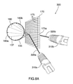
図5Aは、図4のシステム100の変形を図示する。入射レーザビーム120は、レンチキュラシート150のレンチキュラレンズ155への垂直方向184に関してθの入射角を有する。追加的に、入射レーザビーム120は、線184および185を通る面として描かれる、レンチキュラレンズ155を通る水平面に関して角度βだけ角度を付けられる。結果的な屈折光線135および反射光線137が投射される表面はレンチキュラシート150に垂直である。したがって、屈折および反射光線は、弧160および162から構成される円として投射する真円コーン180に近い形をなす。角度βによって、図示されるように、円がレンチキュラシート150に関して上方へ移される。光線135および137は、円を投射するコーン180のように共に整形されるが、しかしながら、コーンは、それが部分的に反射光線から形成されかつ部分的に屈折光線から形成される事実により、部分的にレンチキュラシート150の前に投射されかつ部分的にそれの後ろに投射される。したがって、レーザ源110およびレンチキュラシート150を使用することによってレーザコーンが形成され得る。コーンは、述べたような水平面に関する角度βを変化させることによって上下に向けられ得る。
FIG. 5A illustrates a variant of the
図5Bは、レーザビーム120がレンチキュラシート150のレンズ側に広角度で向けられるのを図示する上方斜視図であり、ここではレンチキュラレンズ155は、レーザビーム120を通る水平面と平行になる。左の弧162は、弧162として投射する反射光線127の形態でシート150の左(レンズ)側のレンチキュラレンズ155から反射するビーム120によって生成される。反対に、右の屈折弧160は、レンチキュラレンズ155を通して屈折し、そして弧160として投射する光線125としてレンチキュラシート150の平滑側から出るビーム120によって生成される。
FIG. 5B is an upward perspective view illustrating the
以上の結果により、ビームがレンチキュラ材料から、線130および135、弧140および142ならびに弧160および162などの形状へ拡散されるにつれてレーザ面またはコーンを生成できることが明らかになる。ミラーを回すことによって形状を生成するために入射レーザビームが活用され得る一部の先行技術方法とは異なり、本明細書に提示されるシステム100は可動部を有しない。単にレンチキュラシートに関してレーザビームの角度を変化させることによって様々な線、弧およびコーン形状が生成され得る。
These results reveal that a laser surface or cone can be generated as the beam is diffused from the lenticular material into shapes such as
先の図がレーザビームがレンチキュラシートのレンズ側に向けられるのを図示したのに対して、本システムは、代わりにレンチキュラシートの平滑側にレーザビームを投射しつつも動作されたことが留意されるべきである。例えば、図6を参照して、ビーム120は片面レンチキュラシート150の平滑側152に向けられる。この場合、形成された左の弧160は、シートを通して屈折し、そして弧160を形成する光線135としてシートのレンズ側のレンチキュラレンズ155から出たビームによる。反対に、図の右の弧162は、弧162を形成する光線137としてレンチキュラシート150の平滑側から反射したレーザビーム120により形成される。追加的に、レンチキュラシート150の平滑側からの鏡面反射を受けたビーム120による弧162の中央に明るいドット167も形成される。屈折弧160が反射弧162より明るいことが観察されている。例外が反射弧上の明るいドット167である。これにより、レンチキュラシートのレンズ側151を使用してレーザコーンを発生させることが好まれることが明らかになった。ビーム120がレンチキュラシート150に関して僅かな程度だけ角度を付けられるにつれて、明るいドット167が弧162に沿って移動可能であることも観察されている。更には、レンチキュラシート150の平滑面に関するビーム120の角度がその表面に垂直であることに近づくにつれて、明るいドット167の強度は増加する。弧162に沿って移動可能である明るいドット167に関してなされた観察は、レンチキュラレンズ155に対する入射レーザビーム120の角度への小さな変化が光線137および135を回転させるという指摘である。本質的に、入射角を変化させることはコーンをサイズ変更することであり、この際、弧160および162上の全てのドットは、コーンがサイズ変更されるにつれてそれらが拡縮するとき、周方向に回転する。例えば、入射角θを小量だけ減少させることで、光線137および135に僅かに大きなコーン180を生成させる。弧160および162を形成する個々のドットがそれらの新たな位置に向けて移動するにつれて、それらは周方向にも動いている。入射角θが増加されるときには反対のことが起こり、コーン180は縮小し、そして弧160および162を形成する個々のドットは、それらが新たな位置に移動するにつれて反対方向に回転する。このことは、入射レーザビームがレンチキュラレンズのレンズ側151に向けられるときにも当てはまると確認されている。ドット(したがってドットを投射するビーム)の回転は、最初は明るいドット167の存在により平滑側152に関して観察されたが、しかしそれは弧160および162を形成する全てのドットに当てはまる。したがって、点を周方向に移動させるために入射角θの微調節を使用できる。このことは、生成されたレーザコーンの応用について述べることに関しては有意な利点を有する。
It should be noted that while the previous figure illustrated the laser beam directed towards the lens side of the lenticular sheet, the system instead projected the laser beam onto the smooth side of the lenticular sheet while operating. Should be. For example, with reference to FIG. 6, the
レーザビームを拡散することならびに/またはレーザ面、曲面もしくはコーンの形態のレーザ光線を有する様々な線、弧および楕円形状を投射することに利益がある。例えば、細い、集光レーザビームを使用するセキュリティシステムは、ビームを遮断するいずれの小物体によってもトリガされるようである。したがって、ビームを通過する昆虫、小鳥または齧歯類のために多くの偽陽性トリガが発生し得る。しかしながら、ビームが拡散されて面(線として投射される)、曲面(弧として投射される)またはコーン(円として投射される)になれば、ビームのより大きな部分を遮断してアラート条件をトリガするには、人間、ドローンまたは車両などのより大きな物体を要し得る。様々な領域に対して条件が変化または変更し得るので、面およびコーンのサイズも変更できる。有利には、レーザ面またはコーンの寸法を変化させることは、レンチキュラレンズへの入射レーザビームの投射の角度および/または位置を変化させる簡単なことである。追加的または代替的に、各々異なる視角またはレンズ密度(LPI)の異なるレンチキュラシートが使用され得る。例えば、同じ角度で投射される1つまたは複数の同じレーザビームに対して、異なる視角のレンチキュラシートが異なる寸法の投射レーザコーンまたは面を生成し得る。 It is beneficial to diffuse the laser beam and / or to project various lines, arcs and elliptical shapes with a laser beam in the form of a laser surface, curved surface or cone. For example, a security system that uses a thin, focused laser beam appears to be triggered by any small object that blocks the beam. Therefore, many false positive triggers can occur for insects, birds or rodents that pass through the beam. However, if the beam is diffused into a surface (projected as a line), a curved surface (projected as an arc) or a cone (projected as a circle), it blocks a larger portion of the beam and triggers an alert condition. This may require a larger object such as a human, drone or vehicle. Since the conditions can change or change for different areas, the size of the faces and cones can also be changed. Advantageously, changing the dimensions of the laser surface or cone is as simple as changing the angle and / or position of the projection of the incident laser beam onto the lenticular lens. Additional or alternative, different lenticular sheets with different viewing angles or lens densities (LPI) may be used. For example, for the same laser beam projected at the same angle, lenticular sheets with different viewing angles may produce projected laser cones or surfaces of different dimensions.
図7Aおよび図7Bを参照して、レーザコーン180を投射するためのシステム200が提供される。システム200は、2つのレーザ源210aおよび210bならびに両面レンチキュラシート170から構成される。両面レンチキュラシート170は、その両側に複数の長手方向のレンチキュラレンズ175を有する。レーザ源210aは第1の色を有する入射レーザビーム220aを投射し、そしてレーザ源210bは第1の色と異なる第2の色を有する入射レーザビーム220bを投射する。例えば、レーザビーム220aが緑でよい一方、レーザビーム220bは赤でよい。入射レーザビーム220aおよび220bは両方とも、両面レンチキュラシート170の反対側に、かつ異なる入射角で向けられる。入射レーザビーム220aは、光線137の形態でレンチキュラシートのレンチキュラレンズ175aの片側から反射される。光線137が平面に当たるまたは接触すると、それらはレンチキュラシート170の前に弧180aを投影する。入射レーザビーム220bは、他方で、レンチキュラシート170に垂直方向に対してより小さな入射角でレンチキュラレンズ175aの反対側に投射される。そのため、ビーム220bはレンチキュラシート170の後側に投射し、そしてレンチキュラレンズ175aから反射される。レンズ175aから反射して光線135として反射される光線は、部分コーンなどの曲面を形成し、レンチキュラシートの前に弧180bを投影する。有利には、2つのビームが両面レンチキュラシート170の特定のレンチキュラレンズの同じ場所の反対側に投射される限り、2つの弧180aおよび180bは相補的である。光線135および光線137から構成される結果的な光線構成はコーン180の形状である。入射レーザビーム220aの入射角は、光線の大部分が光線137として反射されるように選ばれる一方、入射レーザビーム220bの角度は、光線の大部分が光線135としてより高濃度で反射されるように選ばれる。レーザ源210aの入射角が十分に大きければ、レーザビーム220aは、レンチキュラシート170を通過して、弧180bの近くの他の側または弧180bの上に弧状に屈折することになる。
A
図7Bにおいて、入射レーザビーム220aおよび220bの入射角は両方とも、両ビームが両面レンチキュラレンズ170のそれぞれの表面から反射されるように大きい。結果的なレーザコーン180は、このように非常に細いが、完全に反射光線から構成される。
In FIG. 7B, the incident angles of the
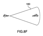
図8Aは、2つのレーザ源310aおよび310bが同じ色のレーザビーム320aおよび320bを投射するシステム300を図示する。したがって、結果的なコーン180は、それが入射レーザビーム320aからの反射光線137および入射レーザビーム320bからの屈折光線135の合成物であるにもかかわらず、同じレーザ源に由来するように見える。結果は、単色である2つのハーフレーザコーン180aおよび180bから構成されるレーザコーン180である。レーザコーン180は、以下に示されるように、幾つかの有用な応用例を有する。
FIG. 8A illustrates a
図8Bは、例えば図8Aのシステム300によって生成されるレーザコーン180が、レーザ源から遠く離れている表面に投影されると、実際には円周ドット182として投射する複数の光線から構成されていることを図示する。典型的な弧およびコーンは何百ものドットから構成される。しかしながら、図6に関して述べたように、入射レーザビームの入射角の微調節がドット182を周方向(時計方向か反時計方向か)に回転させる。したがって、後述するように、これは、それらのドットを投射する光線間を通常は検出されずに通過し得る物体を検出するために使用できる。
FIG. 8B is composed of a plurality of rays, for example, the
ライダ(光検出および測距)は現在、周辺環境から信号を反射させる1つまたは複数のパルスレーザ、および反射信号を検出するためのセンサを活用する。したがって、信号が反射してセンサに戻るのに要する時間を測定することによって、コンピュータは、物体までの距離を決定しかつ/または周辺範囲および表面特性の3次元地図を作成し得る。地形ライダが近赤外レーザを使用して土地の地図を作成し、そして測深ライダがグリーンレーザを使用して、水中に侵入し、海底および河床の地図を作成する。水中でのライダの使用は、しかしながら、しばしば僅か数十フィートに制限される。ライダは自動運転車のキー要素であり、ライダが正確であるほどシステムは安全であり得る。ライダは、航空機の前方の乱流の領域を決定して、航空機がそれらの範囲を回避するまたはそれらに備えるのを許容するために、航空機においてもテストされている。ライダは、浅い水中で、地上で、または空中で(晴天)もしくは宇宙で、目標を探索するために民間組織または軍部によっても使用され得る。低観測性航空機、ドローン、鳥類およびコウモリは、レーダによって検出するのが困難であるが、この種類のシステムによって検出され得る。 Riders (light detection and ranging) currently utilize one or more pulsed lasers that reflect signals from the surrounding environment, as well as sensors for detecting reflected signals. Thus, by measuring the time it takes for the signal to reflect and return to the sensor, the computer can determine the distance to the object and / or create a three-dimensional map of the perimeter and surface characteristics. The terrain rider uses a near-infrared laser to map the land, and the bathymetric rider uses a green laser to infiltrate the water and map the seafloor and riverbed. The use of riders in the water, however, is often limited to only a few tens of feet. Riders are a key element of self-driving cars, and the more accurate the rider, the safer the system can be. Riders have also been tested on aircraft to determine areas of turbulence in front of the aircraft and allow the aircraft to avoid or prepare for those areas. Riders can also be used by civilian organizations or the military to search for targets in shallow water, on the ground, or in the air (sunny) or in space. Low-observability aircraft, drones, birds and bats are difficult to detect by radar, but can be detected by this type of system.
上記システムを活用して、レーザ点の代わりに、平面、曲面および/またはコーンを作成して、センサによって更なる詳細が決定されてより短期間で効果を上げ得る、そして現在のライダシステムより大角度が達成され得る。一実施形態において、空の大きな部分を走査するために、レーザコーンが幅狭から幅広まで可変にされ得る一方、センサは、他の航空機、飛行機雲、航空機乱気流、自然乱気流、ドローン、ミサイル、発射体、ロケット、弾丸、気球、鳥類、コウモリまたは昆虫の群れからのいかなる反射も受信し得る。 Utilizing the above system, instead of laser points, planes, curved surfaces and / or cones can be created, further details determined by the sensor and more effective in a shorter period of time, and greater than current rider systems. The angle can be achieved. In one embodiment, the laser cone can be varied from narrow to wide to scan a large portion of the sky, while the sensor is a sensor for other aircraft, contrails, aircraft turbulence, natural turbulence, drones, missiles, launches. Any reflex from a body, rocket, bullet, balloon, bird, bat or swarm of insects can be received.
図8Cは、機上ライダシステムによって生成される複数の光線137から構成されるレーザコーン180が地上部隊を検出するために使用されるのを図示する。図8Dは、1つまたは複数の敵の部隊を検出するために狙撃兵によって使用されるライダシステムによって使用されるレーザコーンを図示する。図8Eは、複数の光線137から各々構成される3つのレーザコーン180を活用する陸上設置ライダシステムを図示する。陸上設置ライダはミサイルを検出するために使用される。図8Fは、敵機を検出するために使用される機上ライダシステムによって生成されるレーザコーンを描く。図8Gは、地上設置ライダシステムが航空機を検出するためのコーン180を投射するのを描く。図8C〜図8Gに図示されるコーンは、上述したように複数の光線から構成され、図8Bに図示されるように円として投射する。典型的な弧およびコーンは何百ものドットから構成される。検出されるべき物体が2つの周方向に隣接する光線間を通過しないことを保証するために、光線は、各光線がその現在の場所と隣接する光線の場所との間に円弧を引くように周方向に移動される。一実施形態において、これは、レンチキュラレンズに関する1つまたは複数の入射レーザビームの入射角を変化させる、レーザ源の微調節によって達成される。別の実施形態において、述べたように屈折光線が周方向に僅かに回転されるように1つまたは複数の入射レーザビームの入射角を変化させるために、レンチキュラシートが僅かに移動または回転される。
FIG. 8C illustrates a
図9Aは、両面レンチキュラシート170ならびに2つのレーザ源210aおよび210bから構成されるシステム200を図示する。レーザ源210aは入射レーザビーム220aを投射し、そしてレーザ源210bは入射レーザビーム220bを投射する。レーザビーム220aは、先に記載したように、反射弧270aおよび屈折弧270bを生成する。同様に、レーザビーム220bは反射弧280aおよび屈折弧280bを生成する。レーザビーム220bは、レーザビーム220aのそれより大きい角度だけレンチキュラシート170への垂直方向184に角度を付けられる。したがって、入射レーザビーム220bによって生成される弧280aおよび280bは、入射レーザビーム220aによって生成される弧270aおよび270bより寸法が大きい。結果的に、ビーム220bからの反射および屈折光線によって形成されるレーザコーン280は、ビーム220aからの反射および屈折光線によって形成されるレーザコーン270より大きい。ビーム220aおよび220bが同じレンチキュラレンズの各々の側に投射されるので、2つのコーンは同軸である。描かれた実施形態において、レーザビームはレンチキュラレンズの異なる横方向の点に向けられ、それらは距離(d)だけ水平に離隔される。結果的なコーンは、したがって、コーン280内部を進行する物体がコーン270によって検出され得るように入れ子状である。レーザ源210aは、距離(d)を変更するために水平面において移動され得る。したがって、コーン280に関するコーン270のサイズおよび位置が変更する。結果的な効果は、コーン270および280間の全容量が、コーン間のいかなる物体も検出するために使用され得るレーザ光線によって掃引および網羅され得るということである。
FIG. 9A illustrates a double-sided
一実施形態において、レーザ源210aは、例えばコーン270および280間の容量を掃引するために前後に移動され得、追加的に、レーザ源210aは、コーン270を形成する光線を回転させるために、その入射角が僅かに変更され得る。例えば図9Bを参照して、ドット271は、平面に投影されるときのコーン270の光線を表す。同様に、ドット281は、平面に投影されるときのコーン280の光線を表す。コーン270が拡大するより図9Aにおける距離(d)が小さくなるようにレーザ源210aが移動されれば、ドット271はドット281に近づく。更には、レーザ源210aが僅かに角度を付けられて、各ドット271を隣接するドットによって以前に占められていた場所に回転させれば、コーン270および280間の容量は径方向にも周方向にも物体検出のために完全に網羅される。別の実施形態において、コーン280が小さくなるようにレーザ源210bが移動され、そしてコーン270がほとんど消滅されるまでそれが小さくなるようにレーザ源210aが移動される。これは、レーザ源210aがレンチキュラシート170への垂直方向から大きい鈍角(180度近く)であるまでそれに角度を付けることによってなされる。したがって、レーザコーン280によって包含される全容量は物体検出のために掃引される。例えば、コーン270はコーン280の半分のサイズでよく、そしてコーン280がコーン270の初期サイズに一致するまでサイズが減少されるのに、コーン270のサイズがほとんど消滅されるのに要するのと同じ時間要してよい。その時間の間、コーン280の全容量が径方向に掃引される。代替的に、更に少数のレーザ源が追加され、そしてそれらのそれぞれのビームも(d)などの距離だけ互いから変位されるように向けられ得る。したがって、最外レーザコーン280によって包含される容量を網羅するために、幾つかの同心コーンが活用され得る。そのような実施形態において、レーザコーンのサイズを変更することは必要でなくてよく、各コーン領域が周方向に掃除されるように単にそれらを回転させることで十分であり得る。
In one embodiment, the
固定レーザコーンも、コーン角度の可変よりはむしろ、レーダまたはライダがするように回転され得る。ライダは、しばしばミラーを使用してレーザ源を急速に回すが、これらの線、弧またはコーンに関しても同じことが発生し得る。コーンの回転および幅狭から幅広までのコーンの可変角度の組合せも使用され得、そして走査される範囲を増加させるため、2つ以上のレーザが同様または異なる角度の多重コーンのために使用され得、また同じレンズまたは他のレンズと共に使用され得る。可変角度の多重コーンのために2つ以上のレーザが使用されて、レーザコーンは固定でよい。空間では、このシステムは、自然(隕石、小惑星、彗星...)であろうと人工(衛星、宇宙船、宇宙飛行士、宇宙廃品...)であろうと、他の宇宙ベースの物体を検出するために使用され得る。 Fixed laser cones can also be rotated as radars or riders do, rather than variable cone angles. Riders often use mirrors to turn the laser source rapidly, but the same can happen with these lines, arcs, or cones. A combination of cone rotation and variable angles of the cone from narrow to wide can also be used, and two or more lasers can be used for multiple cones of similar or different angles to increase the range scanned. , Also may be used with the same lens or other lenses. Two or more lasers are used for variable angle multiple cones and the laser cones may be fixed. In space, the system detects other space-based objects, whether natural (meteorites, asteroids, comets ...) or man-made (satellite, spacecraft, astronauts, space junk ...). Can be used to
図10Aを参照して、弧140として投射する部分レーザコーンを生成するために、図1〜図6に図示されるそれと同様のシステム100が使用できる。レーザ源110は、シート150などの片面レンチキュラシートのレンズ側151の表面に垂直な線184に対して大角度θだけ角度を付けられている入射レーザビーム120を投射する。これは、弧140として投射する反射光線127の形態で、入射レーザビーム120の光線の反射だけを生成する。上述したように、角度θを更に増加させることで、弧は最終的に完全に消滅されるに至る。
With reference to FIG. 10A, a
両面レンチキュラシート170からのレーザビームの反射だけによって生成される円形コーンを生成するために、入射レーザビーム120の入射角はレンチキュラシートへの垂直方向に関して大きい必要があることが観察されている。角度が十分大きくなければ、光線の一部が屈折され、他の一部が反射される。結果的なパターンは、1つの代わりに2つのコーンであり得る。図10Bに図示されるシステムでは、両面レンチキュラシート170は、2つの背中合わせの片面レンチキュラレンズシート150およびその間に挿入される明るい不透明材料のシート160またはミラーと置き換えられている。この構成では、明るい不透明材料またはミラーは、レンチキュラレンズシートを通したレーザビームの屈折を防止し、代わりにビームを反射する。したがって、角度が、例えば図10Aで使用される角度より大きくなり得るので、結果的なパターンは、より大きなコーンであり得る。
It has been observed that the angle of incidence of the
図10Cは、図10Bのそれと同様のシステムを図示するが、高反射レンズ側を各々有する2つの背中合わせのレンチキュラシート250を使用する。例えば、レンチキュラシート250のレンチキュラレンズは、高反射材料から製作されても、または高反射コーティングを有してもよい。レンズ側の高反射は、レンチキュラレンズシートを通したレーザビームの屈折を防止し、代わりにビームを反射する。したがって、角度が、例えば図10Aで使用される角度より大きくなり得るので、結果的なパターンは、より大きなコーンであり得る。
FIG. 10C illustrates a system similar to that of FIG. 10B, but uses two back-to-back
レーザ源は、レンチキュラシートに関して僅かに左にまたは右に移動されて、ドットを時計方向にまたは反時計方向に移動させ得る。各投影ドットがそれに隣接するものに近接していれば、各ドットに次の隣接するドット位置への間隔を横切らせるために、レーザ源によるごく僅かな移動しか必要とされなくてよい。別の考え得る実施形態は、レンチキュラシート自体を移動させることである。ドットを移動させて間隔を横切るために、シートによるごく僅かな移動しか必要とされない。一実施形態において、レンチキュラシートは円筒の形態でよく、僅かに移動可能であることができる。ゆっくりした着実な移動を生じさせるために単純な歯車およびばね機構が活用され得る。例えば、古いねじ巻き携帯時計と同様の巻取り機構が使用され得る。同機構は、レーザ源およびレーザ源のレーザビームを転向させるために使用されるレンチキュラ材料の一方を回転させるゆっくりだが着実な転回運動を提供するために減速歯車装置を含み得る。同機構が第1のレーザ源に適用されてそれを僅かに左にまたは右に移動すれば、第2のレーザが掃引の最中である間に第1のレーザ源が左端または右端点に到達すると、第2のレーザ源はドットの停止を相殺することを要求され得る。回転ミラーを活用することでも、線、弧またはコーンを回し得る。 The laser source may be moved slightly to the left or right with respect to the lenticular sheet to move the dots clockwise or counterclockwise. If each projected dot is in close proximity to its neighbors, only a small amount of movement by the laser source may be required to make each dot traverse the spacing to the next adjacent dot position. Another possible embodiment is to move the lenticular sheet itself. Very little movement by the sheet is required to move the dots across the spacing. In one embodiment, the lenticular sheet may be in the form of a cylinder and may be slightly mobile. Simple gear and spring mechanisms can be utilized to produce slow and steady movement. For example, a take-up mechanism similar to an old screw-wound portable watch may be used. The mechanism may include a reduction gear device to provide a slow but steady rolling motion that rotates one of the laser source and the lenticular material used to divert the laser beam of the laser source. If the mechanism is applied to the first laser source and it is moved slightly to the left or right, the first laser source will reach the left or right edge while the second laser is in the middle of a sweep. The second laser source may then be required to offset the dot stall. A rotating mirror can also be used to rotate a line, arc or cone.
実験により、形状にかかわらず、ステルス航空機は、ライダによって放出される光の小波長で存在する電磁エネルギーを効果的に散乱させることができないことが明らかになった。高速移動ジェット機または新型の極超音速ミサイルであれば、述べられた転向レーザ光線間の間隔を通って飛行することができ得るが、しかし、述べられたコーンを形成する光線も、レンチキュラレンズかレーザ源かを移動させるによって達成されて、時計方向または反時計方向に移動していれば、そうすることはあまりできそうにない。追加的に、そのような飛行体によって生成される乱流はライダによっても検出され得る。 Experiments have shown that stealth aircraft, regardless of shape, are unable to effectively scatter the electromagnetic energy present at the small wavelengths of light emitted by the rider. High-speed moving jets or new hypersonic missiles may be able to fly through the spacing between the stated turning laser beams, but the rays forming the mentioned cones are also lenticular lenses or lasers. If it is achieved by moving the source or moving clockwise or counterclockwise, it is unlikely that it will be possible. In addition, the turbulence generated by such an air vehicle can also be detected by the rider.
図11は、ライダシステムを使用して物体を検出するための方法1100を描く。ステップ1110で、反射光線の第1のハーフコーンを生成するために両面レンチキュラシートの第1のレンズ側へ第1の入射レーザビームが投射される。ステップ1120で、反射光線の第1のハーフコーンと共に反射光線のフルコーンを形成する反射光線の第2のハーフコーンを生成するために両面レンチキュラシートの第2のレンズ側へ第2の角度で第2の入射レーザビームが投射される。ステップ1130で、物体がフルコーンの反射光線のいずれか1つを横切るときにその物体から反射される信号を、ライダシステムのセンサが検出する。
Figure 11 depicts
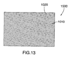
図12は、複数の線1010を有する線形(単軸)回折格子1000の回折側の上面図である。回折格子1000の反対側は円滑平面である。図13は、複数の水平線1010および複数の垂直線1020を有する二軸回折格子1500の回折側の上面図である。二軸回折格子1500の反対側は円滑平面である。
FIG. 12 is a top view of the diffraction side of a linear (single axis)
図14は、入射光ビーム20が法線に角度をなして回折格子1000の平滑面の方へ向けられるのを図示する。ビーム20を含む異色光の光線が、それらがプリズムから屈折されかつ異色の光線21、22、23および24へ分解されるのと同じように屈折される。
FIG. 14 illustrates that the
図15は、入射レーザビーム120が単軸回折格子1000を通して向けられるのを図示する側方斜視図である。単軸回折格子1000は、ビーム120に、壁などの平面に投射されると、その表面に沿って一列に配置される複数のドット1025を生成する複数の回折レーザビーム1024を生成させる。特定の種類のレーザ源が使用され、ミリメートル当たり(l/mm)1000本の線の回折格子により、3つのドットが形成されたことが観察されている。
FIG. 15 is a side perspective view illustrating the
図16は、入射レーザビーム120が二軸回折格子1500を通して向けられるのを図示する側方斜視図である。二軸回折格子1500は、ビーム120に、壁などの平面に投射されると、その表面に行列形状に配置される複数のドット1025を生成する複数の回折レーザビーム1024を生成させる。
FIG. 16 is a side perspective view illustrating the
図1に戻って、レンチキュラ素子155が水平に配向された線形レンチキュラシート150に略垂直に入射レーザ光ビーム120が向けられると、結果的なパターンは、三角形として形成され、かつ平面に垂直線130として投影されるビームであった。各垂直線130は、実際には密な間隔である数百ものドットから構成される。図15からの複数のレーザビーム1024が図1のそれなどのレンチキュラシート150を通過させられれば、図15の回折レーザビーム1024の各個は図1の線130などの線を生成するであろう。図17を参照して、レーザ源110は、回折線が垂直であるように配向される線形回折格子1000に続いて、レンチキュラレンズが水平に配向されて、回折格子1000の後ろに設置されかつ当接する線形レンチキュラシート150を通して入射レーザビーム120を向ける。結果的なパターンは、垂直線1080として投影する複数の三角垂直面である。垂直線の精密検査により、各線が数百もの密な間隔の点から形成されることが明らかになる。垂直線の数は回折格子のパターン密度に依存する。したがって、投影される垂直線の数は増加され得る。
Returning to FIG. 1, when the
図18に関して、レンチキュラレンズシート150が、それが回折格子1000に関して角度を付けられるように回転されれば、回折格子によって投射される点はもはや垂直に整列せず、それらの各個は、線形レンチキュラシートを通過させられると線を生成する。結果的なパターンは、斜線1090として投影し、かつ密な間隔である同数の斜め三角レーザ面である。また、斜線1090の各個は数百もの点から構成される。
With respect to FIG. 18, if the
図19で使用される回折格子は、本開示の実施形態に従って、二軸回折格子1500である。図16に関して前述したように、入射レーザビーム120が二軸回折格子1500を通して投射されると、レーザドットの行列として投射するレーザビームの行列が形成される。例えば、二軸回折格子がインチ当たり13,500の線のパターン密度を有すれば、13×13ドットの行列パターンが回折レーザビームによって投射されると認められた。複数のレンズを持つレンチキュラシート150が回折レーザビーム1024の経路に設置されれば、各ビームは、前に図示されたように線を生成する。レンチキュラレンズが水平に配向されるようにレンチキュラシートが設置されれば、線1080の多くは整列し、そして幾つかの実質的に明るい線が見える。
The diffraction grating used in FIG. 19 is a
図20において、レンチキュラシート150は、二軸回折格子1500に対して或る角度だけ回転される。したがって、回折格子によって生成されるドットの行列は、ここでレンチキュラシート150に斜めに配向される。結果的なパターンは複数の線1090であり、斜めである。線1090は線1080より多く、かつより密な間隔である。線1090の各々は数百ものドットから構成される。
In FIG. 20, the
入射レーザビームの経路に異なるパターン密度のより多くの回折格子シートを追加することで、ドットを形成するより多くの回折ビームを生成することが観察されている。レンチキュラシートに回折光線を通過させることで、述べたように、各ドットを線へ変換し、各線は数百または数千ものドットから構成される。複数のビームの経路へ入り込む物体は数千ものレーザビームの経路にあり、ライダシステムを使用して良好な分解能で検出できる。追加的に、行列の形態で数千ものレーザビームを活用するライダシステムは、小物体に対しても感度が高い。数千ものレーザビームは遠距離でさえ密な間隔であり、レーザコーンを用いて行われるものと同様の掃引を行う必要性を回避し得る。使用される回折格子の数の制限因子は、通過しようとするレーザ光の量およびその強度である。強いレーザは多数の回折格子を用いても使用可能である十分な電力を更に照射し得る一方、弱いレーザは幾つかの回折格子と併せて使用され得るだけである。ライダシステムの応用例は、使用されるレーザの強さ、更にそれに応じて、回折格子の数、それらのパターン密度、ならびにそれらの互いに関するおよびレンチキュラレンズに関する角度を指定し得る。追加的に、検出されるべき物体までの距離は、使用する格子の数を指定し得る。例えば、十分に遠くない物体に対しては、結果的な線およびドットがまだ近距離で密な間隔であるので、少数の格子が使用され得る。しかしながら、遠く離れている物体を検出するために、密な間隔であるより多くのビームを、レンチキュラシートを用いて、生成するより多くの格子が望ましいであろう。格子が多いほどライダを使用して物体を検出する能力に影響を及ぼす通過レーザ光量を低減させるので、その場合、より強いレーザが必要とされる。 It has been observed that by adding more grating sheets with different pattern densities to the path of the incident laser beam, more diffraction beams forming dots are generated. By passing a diffracted ray through the lenticular sheet, each dot is converted into a line, as described, and each line is composed of hundreds or thousands of dots. Objects that enter the path of multiple beams are in the path of thousands of laser beams and can be detected with good resolution using a rider system. In addition, rider systems that utilize thousands of laser beams in the form of a matrix are also sensitive to small objects. Thousands of laser beams are closely spaced even at long distances, avoiding the need for sweeps similar to those performed with laser cones. The limiting factor for the number of diffraction gratings used is the amount and intensity of the laser beam that is going to pass. A strong laser can still irradiate enough power that can be used with a large number of gratings, while a weak laser can only be used in conjunction with some gratings. Applications of the rider system may specify the intensity of the laser used, and accordingly the number of diffraction gratings, their pattern densities, and the angles with respect to each other and with respect to the lenticular lens. In addition, the distance to the object to be detected can specify the number of grids to use. For example, for objects not far enough, a small number of grids may be used, as the resulting lines and dots are still close and closely spaced. However, in order to detect objects that are far apart, it would be desirable to have more grids that produce more beams with close spacing using a lenticular sheet. The more grids there are, the less the amount of passing laser light that affects the ability of the rider to detect objects, so stronger lasers are needed in that case.
図21は、オフセット干渉パターンを間に、2つの背中合わせの線形レンチキュラシート150および450を使用することによってレーザビームを転向させるシステムを図示する。図示されるように、シート150の個々のレンチキュラレンズは、水平方向にシート450のそれらから横にオフセットしている。レンチキュラシート450に向けられる入射レーザビーム120は、それがレンチキュラシート150を出るとき転向光線125として転向される。干渉パターンは、それゆえにレーザビームを偏位させる。近代戦において目標をマークするためにレーザデジグネータがしばしば使用されるので、これは有益である。これは、レーザ誘導爆弾、ミサイルおよび精密火砲弾薬のためになされる。レーザデジグネータを偏位させることによって、しばしば無能力化するために特定の場所の直接的な命中を必要とする、戦車などの目標の弱点を武器が外してしまうという可能性がある。
FIG. 21 illustrates a system that diverts a laser beam by using two back-to-back linear
レーザは、地上軍によってもそれらの武器を敵に向けるためにますます使用されている。これらのレーザは可視スペクトル外の周波数で動作でき、かつ暗視スコープまたはゴーグルを通して見ることができる。図21で使用される材料は、可視スペクトルでだけでなく、UV(紫外)、NIR(近赤外)およびSWIR(短波赤外)ならびに潜在的にこの範囲外のそれらでもレーザを偏位させるために機能する。 Lasers are increasingly being used by the ground forces to point their weapons at the enemy. These lasers can operate at frequencies outside the visible spectrum and can be seen through a night vision scope or goggles. The material used in Figure 21 is to deflect the laser not only in the visible spectrum, but also in UV (ultraviolet), NIR (near infrared) and SWIR (shortwave infrared) and potentially those outside this range. Works for.
レーザのピンポイント精度を偏位させる結果として、兵士が間違った場所を狙って常に目標を外し、命中させることができない理由も理解できないことにもなり得る。目標の状況を隠匿した干渉の分裂的要素により、敵は目標を完全に外したことに気づいてさえおらず、命中させたとみなし得る。これにより、敵に攻撃または防御の姿勢または陣地を変えさせて、隠匿された目標をこちらの材料の背後に置き、戦闘員を容易に見つけて識別し、その敵対者を最も攻撃を受けやすいときに目標とし得る。図21のシステムにより、レーザビームを右に移動させると、それは左に偏向し、逆も同様である。これは矢印によって示されており、偏向レーザビーム125が入射レーザビーム120と反対方向に移動することを図示している。目標を狙っている観察者は、目標上の投影レーザドットが、レーザ源が動かされている方向と反対方向に動いていることに気づき得る。したがって、観察者は、目標の前に何らかの形態の偽装材料が存在すると疑い、観察されるドットを使用して目標に向けて弾薬が発射されても目標は正確には命中されないであろうと結論し得る。
As a result of deviating the pinpoint accuracy of the laser, it can also be difficult to understand why soldiers cannot always aim at the wrong place and hit the target. Due to the splitting element of interference that conceals the situation of the target, the enemy is not even aware that he has completely missed the target and can be considered to have hit. This allows the enemy to change their offensive or defensive posture or position, placing hidden targets behind this material, making it easier to find and identify combatants, and when their adversaries are most vulnerable to attack. Can be a goal. With the system in Figure 21, moving the laser beam to the right deflects it to the left and vice versa. This is indicated by an arrow, which illustrates that the deflecting
図22は、2つの背中合わせの線形レンチキュラシート150および450の代替配置を描く。この配置では、シート150の個々のレンチキュラレンズは、水平方向にシート450のそれらに角度を付けられており、通過する入射レーザビームを偏位させる干渉パターンを生成する。
Figure 22 depicts an alternative arrangement of two back-to-back linear
図23は、オフセット干渉パターンを間に、2つの背中合わせの線形レンチキュラシート150および450、ならびに追加の両面レンチキュラシート170を使用することによってレーザビームを転向させるシステムを図示する。図示されるように、シート150の個々のレンチキュラレンズは、水平方向にシート450のそれらからオフセットしている。両面レンチキュラシート170は、レーザ源とレンチキュラシート450および150との間に位置付けられるのを図示されるが、しかしながらレンチキュラシート170は、レンチキュラ150および450の後ろに位置付けられてもよい。レンチキュラシート450に向けられる入射レーザビーム120は、図21における場合のように転向ビームとしてレンチキュラシート150を出るが、しかしながらその転向ビームは、ここでは両面レンチキュラシート170を通過する。この場合、ビームは、レーザ源が特定方向に動かされると転向され、転向ビーム125は同じ方向に移動する。有利には、転向ビームは設定目標に投射しないが、しかし同時に、レーザ源を動かすと、投影レーザドットが同じ方向に移動するように見えるので、観察者は、ビームが転向されているとは疑わない可能性がある。したがって、観察者は、観察された投影ドットの方向に弾薬が発射されると、目標が命中されたという印象下にいる可能性がある。
FIG. 23 illustrates a system that diverts a laser beam by using two back-to-back linear
レンチキュラレンズが実質的に同じ寸法に描かれたが、異なる角度またはインチ当たりのレンズ(LPI)の異なるレンチキュラシートが、本発明が機能する仕方に影響を及ぼすことなく互換的に使用され得ることは当業者にとって明らかであろう。 Although lenticular lenses are drawn to substantially the same dimensions, different lenticular sheets with different angles or lenses per inch (LPI) can be used interchangeably without affecting how the invention works. It will be obvious to those skilled in the art.
例証的な実施形態で使用されるレンチキュラシートが長手方向のレンチキュラシートから成ったが、他の同等の屈折反射材料が使用可能であり得る。例えば、プリズムレンズ、ダブプリズムレンズ、および中央で分割されたダブプリズムレンズが使用され得る。 Although the lenticular sheet used in the exemplary embodiment consists of a longitudinal lenticular sheet, other equivalent refraction reflective materials may be used. For example, prism lenses, dub prism lenses, and centrally split dub prism lenses can be used.
レンチキュラレンズおよび/または回折格子を使用する本明細書に記載される全てのシステムに対して、その表面は、霧、水、火、泥、塵、傷、熱、寒さおよび紫外線放射を含むがこれらに限定されない、以下の一部または全てに対処し得る保護要素で被覆または製造され得る。 For all systems described herein using lenticular lenses and / or gratings, the surfaces include fog, water, fire, mud, dust, scratches, heat, cold and UV radiation. It may be coated or manufactured with a protective element that can address some or all of the following, including but not limited to:
このように本発明の実施形態を単に例として記載したが、添付の特許請求の範囲によって定められる本発明が、例証的な実施形態の上記説明に記載される特定の詳細によって限定されるものではなく、多くの変形および置換が特許請求の範囲から逸脱することなく可能であることが理解されるはずである。 Thus, embodiments of the invention are described merely as examples, but the invention as defined by the appended claims is not limited by the particular details described in the above description of the exemplary embodiments. It should be understood that many modifications and substitutions are possible without departing from the claims.
20 入射光ビーム
21 光線
22 光線
23 光線
24 光線
100 システム
110 レーザ源
120 入射レーザビーム、入射レーザ光ビーム
125 転向光線、偏向レーザビーム、転向ビーム
126 転向光線
127 反射光線
128 三角平面
129 三角平面
130 垂直線パターン、線
132 小線
135 水平線パターン、転向光線、屈折光線、線
137 反射光線
138 曲面
140 弧パターン、弧
142 小弧
150 線形レンチキュラシート
151 レンズ側
152 平滑側
155 レンチキュラレンズ、レンチキュラ素子
160 弧、屈折弧、シート
162 弧、反射弧
165 楕円
167 ドット
170 両面レンチキュラシート
175 レンチキュラレンズ
180 コーン、レーザコーン
180a 弧、ハーフレーザコーン
180b 弧、ハーフレーザコーン
182 円周ドット
184 線、垂線、垂直方向
185 線
200 システム
210a レーザ源
210b レーザ源
220a 入射レーザビーム
220b 入射レーザビーム
250 レンチキュラシート
270 レーザコーン
270a 反射弧
270b 屈折弧
271 ドット
280 レーザコーン
280a 反射弧
280b 屈折弧
281 ドット
450 線形レンチキュラシート
1000 線形(単軸)回折格子
1010 線、水平線
1020 垂直線
1024 回折レーザビーム
1025 ドット
1080 垂直線
1090 斜線
1500 二軸回折格子
β 角度
θ 水平入射角、大角度
20 Incident light beam
21 rays
22 rays
23 rays
24 rays
100 systems
110 laser source
120 Incident laser beam, Incident laser beam
125 Converting Rays, Deflection Laser Beams, Converting Beams
126 Converting rays
127 reflected rays
128 Triangular plane
129 Triangular plane
130 vertical line pattern, line
132 small line
135 horizon pattern, turning rays, refracting rays, lines
137 Reflected rays
138 Curved surface
140 arc pattern, arc
142 small arc
150 Linear lenticular sheet
151 Lens side
152 Smooth side
155 Lenticular lens, lenticular element
160 arc, refraction arc, sheet
162 arc, reflex arc
165 ellipse
167 dots
170 Double-sided lenticular sheet
175 Lenticular lens
180 cones, laser cones
180a arc, half laser cone
180b arc, half laser cone
182 Circumferential dots
184 lines, vertical lines, vertical direction
185 line
200 system
210a laser source
210b laser source
220a Incident laser beam
220b Incident laser beam
250 lenticular sheet
270 laser cone
270a reflex arc
270b refraction arc
271 dots
280 laser cone
280a reflex arc
280b refraction arc
281 dots
450 Linear Lenticular Sheet
1000 Linear (single axis) diffraction grating
1010 line, horizon
1020 vertical line
1024 diffracted laser beam
1025 dots
1080 vertical line
1090 diagonal line
1500 Biaxial diffraction grating β angle θ Horizontal incident angle, large angle
Claims (34)
ドットとして投射する複数の光線を含む入射レーザビームを放出するレーザ源と、
複数の平行な長手方向のレンチキュラレンズを含むレンズ側および前記レンズ側と反対の平滑側を有するレンチキュラシートと
を備え、
前記レーザ源が、前記入射レーザビームが前記複数の平行な長手方向のレンチキュラレンズの少なくとも1つに当たるように前記レンチキュラシートの前記レンズ側の方へ向けられ、
前記入射レーザビームの前記複数の光線の第1の部分が屈折によって転向されて、第1の形状の屈折ビームを形成し、
前記入射レーザビームの前記複数の光線の第2の部分が前記複数の平行な長手方向のレンチキュラレンズの前記少なくとも1つの表面によって反射されて、第2の特定形状の反射ビームを形成する、
システム。 A system for turning a laser beam,
A laser source that emits an incident laser beam containing multiple rays projected as dots,
It comprises a lens side including a plurality of parallel longitudinal lenticular lenses and a lenticular sheet having a smooth side opposite to the lens side.
The laser source is directed towards the lens side of the lenticular sheet so that the incident laser beam hits at least one of the plurality of parallel longitudinal lenticular lenses.
The first portion of the plurality of rays of the incident laser beam is turned by refraction to form a refracted beam of first shape.
A second portion of the plurality of rays of the incident laser beam is reflected by said at least one surface of the plurality of parallel longitudinal lenticular lenses to form a second particular shaped reflected beam.
system.
屈折によって転向される前記入射レーザビームの前記第1の部分が前記入射レーザビームの前記複数の光線の大半を表し、第1の特定形状の前記屈折ビームが、直線として投射される三角面ビームの形態である、請求項1に記載のシステム。 The laser source is directed so that the first incident laser beam hits at least one of the plurality of parallel longitudinal lenticular lenses perpendicularly.
The first portion of the incident laser beam turned by refraction represents most of the plurality of rays of the incident laser beam, and the refraction beam of the first specific shape is projected as a straight line of a triangular surface beam. The system according to claim 1, which is a form.
前記少なくとも1つの回折格子は、その複数の線が垂直に配向されるように配向される少なくとも1つの線形回折格子を含む、請求項9または10に記載のシステム。 The lenticular sheet is installed in an upright position such that the plurality of parallel longitudinal lenses are oriented at an angle to a horizontal plane.
The system according to claim 9 or 10, wherein the at least one diffraction grating comprises at least one linear diffraction grating in which the plurality of lines are oriented so as to be vertically oriented.
前記少なくとも1つの回折格子は、その第1の複数の線が垂直に配向され、その第2の複数の線が水平に配向されるように配向される少なくとも1つの二軸回折格子を含む、請求項9または10に記載のシステム。 The lenticular sheet is installed in an upright position so that the plurality of parallel longitudinal lenses are horizontally oriented.
The at least one diffraction grating comprises at least one biaxial diffraction grating in which the first plurality of lines are oriented vertically and the second plurality of lines are oriented horizontally. The system according to item 9 or 10.
前記少なくとも1つの回折格子は、その第1の複数の線が垂直に配向され、その第2の複数の線が水平に配向されるように配向される少なくとも1つの二軸回折格子を含む、請求項9または10に記載のシステム。 The lenticular sheet is installed in an upright position such that the plurality of parallel longitudinal lenses are oriented at an angle to a horizontal plane.
The at least one diffraction grating comprises at least one biaxial diffraction grating in which the first plurality of lines are oriented vertically and the second plurality of lines are oriented horizontally. The system according to item 9 or 10.
ドットに投射する複数の光線から構成される第1の入射ビームを生成する第1のレーザ源と、
ドットに投射する複数の光線から構成される第2の入射ビームを生成する第2のレーザ源と、
複数の平行な長手方向のレンチキュラレンズを含む第1のレンズ側および前記第1のレンズ側と反対の複数の平行な長手方向のレンチキュラレンズを含む第2のレンズ側を有する両面レンチキュラシートと
を備え、
前記第1のレーザ源は、前記第1の入射ビーム光線の大半が反射されて第1の曲面を形成するような入射角で前記第1の入射ビームが前記複数の平行な長手方向のレンチキュラレンズの1つに当たるように前記両面レンチキュラシートの前記第1のレンズ側の方へ向けられ、
前記第2のレーザ源は、前記第2の入射ビーム光線の大半が屈折されて第2の曲面を形成するような前記第1のレーザ源と同じ入射角で前記第2の入射ビームが前記複数の平行な長手方向のレンチキュラレンズの前記1つの反対側に当たるように前記両面レンチキュラシートの前記第2のレンズ側の方へ向けられ、
前記第1の曲面および前記第2の曲面が、円として投射されるコーンを共に形成する、
システム。 A system for manipulating two laser beams to form a cone.
A first laser source that produces a first incident beam composed of multiple rays projected onto a dot,
A second laser source that produces a second incident beam composed of multiple rays projected onto the dots,
A double-sided lenticular sheet having a first lens side containing a plurality of parallel longitudinal lenticular lenses and a second lens side including a plurality of parallel longitudinal lenticular lenses opposite to the first lens side. ,
The first laser source is a plurality of parallel longitudinal lenticular lenses in which the first incident beam has an incident angle such that most of the first incident beam rays are reflected to form a first curved surface. The double-sided lenticular sheet is directed toward the first lens side so as to hit one of the above.
The second laser source has a plurality of the second incident beams at the same incident angle as the first laser source such that most of the second incident beam rays are refracted to form a second curved surface. Directed towards the second lens side of the double-sided lenticular sheet so as to hit the opposite side of the one in the parallel longitudinal direction of the lenticular lens.
The first curved surface and the second curved surface together form a cone projected as a circle.
system.
前記第1および第2の片面レンチキュラシートは、前記第1および第2の片面レンチキュラシートのそれぞれの平滑側において背中合わせに位置付けられる、請求項15に記載のシステム。 The double-sided lenticular sheet comprises a first and second single-sided lenticular sheet having a lens side and a smooth side, respectively.
15. The system of claim 15, wherein the first and second single-sided lenticular sheets are positioned back-to-back on the smooth side of each of the first and second single-sided lenticular sheets.
ドットに投射する複数の光線から構成される第1の入射ビームを生成する第1のレーザ源と、
ドットに投射する複数の光線から構成される第2の入射ビームを生成する第2のレーザ源と、
複数の平行な長手方向のレンチキュラレンズを含む第1のレンズ側および前記第1のレンズ側と反対の複数の平行な長手方向のレンチキュラレンズを含む第2のレンズ側を有するレンチキュラシートと
を備え、
前記第1のレーザ源は、前記第1の入射ビーム光線が屈折および反射されて第1のコーンを形成するような第1の入射角で前記第1の入射ビームが前記複数の平行な長手方向のレンチキュラレンズの1つに当たるように前記レンチキュラシートの前記第1のレンズ側の方へ向けられ、
前記第2のレーザ源は、前記第2の入射ビーム光線が屈折および反射されて、前記第1のコーンより大きくかつそれと同軸の第2のコーンを形成するような前記第1の入射角より大きい入射角で前記第2の入射ビームが前記複数の平行な長手方向のレンチキュラレンズの前記1つの反対側に当たるように前記レンチキュラシートの前記第2のレンズ側の方へ向けられる、
システム。 A system for manipulating two laser beams to form a cone.
A first laser source that produces a first incident beam composed of multiple rays projected onto a dot,
A second laser source that produces a second incident beam composed of multiple rays projected onto the dots,
It comprises a first lens side containing a plurality of parallel longitudinal lenticular lenses and a lenticular sheet having a second lens side including a plurality of parallel longitudinal lenticular lenses opposite to the first lens side.
The first laser source has a first angle of incidence such that the first incident beam beam is refracted and reflected to form a first cone, and the first incident beam is directed in the plurality of parallel longitudinal directions. Aimed toward the first lens side of the lenticular sheet so as to hit one of the lenticular lenses of the
The second laser source is larger than the first angle of incidence such that the second incident beam beam is refracted and reflected to form a second cone that is larger and coaxial with the first cone. At the angle of incidence, the second incident beam is directed towards the second lens side of the lenticula sheet such that the second incident beam hits the opposite side of the one of the plurality of parallel longitudinal lenticular lenses.
system.
反射光線の第1のハーフコーンを生成するために両面レンチキュラシートの第1のレンズ側へ第1の角度で第1の入射レーザビームを投射するステップと、
反射光線の前記第1のハーフコーンと共に反射光線のフルコーンを形成する反射光線の第2のハーフコーンを生成するために前記両面レンチキュラシートの第2のレンズ側へ第2の角度で第2の入射レーザビームを投射するステップと、
前記ライダシステムの少なくとも1つのセンサによって、少なくとも1つの物体が前記フルコーンの前記反射光線のいずれか1つを横切るときに前記少なくとも1つの物体から反射される信号を検出するステップと、
を含む、方法。 A method of detecting at least one object using a photodetection and ranging (rider) system.
A step of projecting a first incident laser beam at a first angle to the first lens side of a double-sided lenticular sheet to generate a first half-cone of reflected rays,
A second incident at a second angle on the second lens side of the double-sided lenticula sheet to generate a second half-cone of the reflected light that forms a full cone of the reflected light with the first half-cone of the reflected light. The step of projecting a laser beam and
A step of detecting a signal reflected from the at least one object as the at least one object crosses any one of the reflected rays of the full cone by at least one sensor of the rider system.
Including, how.
入射レーザビームを投射するためのレーザ源と、
複数の平行な長手方向のレンチキュラレンズを含むレンズ側および前記第1の側と反対の平滑側を有する第1のレンチキュラシートと、
複数の平行な長手方向のレンチキュラレンズを含むレンズ側および前記第1の側と反対の平滑側を有する第2のレンチキュラシートと、
を備え、
前記第1のレンチキュラシートおよび前記第2のレンチキュラシートが、前記第1のレンチキュラシートの前記平滑側が前記第2のレンチキュラシートの前記平滑側に向かうように位置付けられ、前記第1のレンチキュラシートおよび前記第2のレンチキュラシートが両面レンチキュラシートを形成し、
前記レーザ源が、前記第1のレンチキュラシートおよび前記第2のレンチキュラシートを通して前記入射レーザビームを投射する、
システム。 A system for turning a laser beam,
A laser source for projecting an incident laser beam and
A first lenticular sheet having a lens side containing a plurality of parallel longitudinal lenticular lenses and a smooth side opposite to the first side.
A second lenticular sheet having a lens side containing a plurality of parallel longitudinal lenticular lenses and a smooth side opposite to the first side.
Equipped with
The first lenticular sheet and the second lenticular sheet are positioned such that the smooth side of the first lenticular sheet faces the smooth side of the second lenticular sheet, and the first lenticular sheet and the above. The second lenticular sheet forms a double-sided lenticular sheet,
The laser source projects the incident laser beam through the first lenticular sheet and the second lenticular sheet.
system.
複数の平行な長手方向のレンチキュラレンズを含むレンズ側および前記第1の側と反対の平滑側を有する第1のレンチキュラシートを設けるステップと、
複数の平行な長手方向のレンチキュラレンズを含むレンズ側および前記第1の側と反対の平滑側を有する第2のレンチキュラシートを設けるステップと、
前記第1のレンチキュラシートの前記平滑側を前記第2のレンチキュラシートの前記平滑側に付着させるステップと
を含む、方法。 It is a method of making a system for deviating a laser beam.
A step of providing a first lenticular sheet having a lens side containing a plurality of parallel longitudinal lenticular lenses and a smooth side opposite to the first side.
A step of providing a second lenticular sheet having a lens side containing a plurality of parallel longitudinal lenticular lenses and a smooth side opposite to the first side.
A method comprising the step of adhering the smooth side of the first lenticular sheet to the smooth side of the second lenticular sheet.
前記両面レンチキュラシートを、前記両面レンチキュラシートの前記複数の平行な長手方向のレンチキュラレンズが前記第1のレンチキュラシートの前記複数の平行な長手方向のレンチキュラレンズまたは前記第2のレンチキュラシートの前記複数の平行な長手方向のレンチキュラレンズのいずれかと平行であるように前記第1のレンチキュラシートの前記レンズ側にまたは前記第2のレンチキュラシートの前記レンズ側に付着させるステップと
を更に含む、請求項32または33に記載の方法。 With the step of providing a double-sided lenticular sheet having a first lens side containing a plurality of parallel longitudinal lenticular lenses and a second lens side including a plurality of parallel longitudinal lenticular lenses opposite the first side. ,
The double-sided lenticular sheet, the plurality of parallel longitudinal lenticular lenses of the double-sided lenticular sheet may be the plurality of parallel longitudinal lenticular lenses of the first lenticular sheet or the plurality of parallel longitudinal lenticular lenses of the second lenticular sheet. 32. The method described in 33.
Applications Claiming Priority (5)
| Application Number | Priority Date | Filing Date | Title |
|---|---|---|---|
| US201862732240P | 2018-09-17 | 2018-09-17 | |
| US62/732,240 | 2018-09-17 | ||
| CAPCT/CA2019/000019 | 2019-02-13 | ||
| PCT/CA2019/000019 WO2019161478A1 (en) | 2018-02-20 | 2019-02-13 | Display system |
| PCT/CA2019/000097 WO2020056484A1 (en) | 2018-09-17 | 2019-06-26 | System and methods for laser scattering, deviation and manipulation |
Publications (2)
| Publication Number | Publication Date |
|---|---|
| JP2022501619A true JP2022501619A (en) | 2022-01-06 |
| JPWO2020056484A5 JPWO2020056484A5 (en) | 2022-07-05 |
Family
ID=69886732
Family Applications (1)
| Application Number | Title | Priority Date | Filing Date |
|---|---|---|---|
| JP2021538869A Pending JP2022501619A (en) | 2018-09-17 | 2019-06-26 | Systems and methods for laser scattering, deviation and manipulation |
Country Status (11)
| Country | Link |
|---|---|
| US (1) | US20220035078A1 (en) |
| EP (1) | EP3853643A4 (en) |
| JP (1) | JP2022501619A (en) |
| KR (1) | KR20210074297A (en) |
| CN (1) | CN112888972B (en) |
| AU (1) | AU2019342087A1 (en) |
| CA (1) | CA3113111A1 (en) |
| EA (1) | EA202190797A1 (en) |
| IL (1) | IL281588A (en) |
| WO (1) | WO2020056484A1 (en) |
| ZA (1) | ZA202102443B (en) |
Families Citing this family (3)
| Publication number | Priority date | Publication date | Assignee | Title |
|---|---|---|---|---|
| US11892652B1 (en) * | 2020-04-07 | 2024-02-06 | Mark Belloni | Lenses for 2D planar and curved 3D laser sheets |
| CN114442851A (en) * | 2022-01-28 | 2022-05-06 | 深圳Tcl新技术有限公司 | Laser processing method, laser processing device, storage medium, display device and laser device |
| KR102496330B1 (en) * | 2022-05-18 | 2023-02-06 | 두원포토닉스 주식회사 | Laser device for aircraft defense and operating method thereof |
Family Cites Families (12)
| Publication number | Priority date | Publication date | Assignee | Title |
|---|---|---|---|---|
| JPH10253916A (en) * | 1997-03-10 | 1998-09-25 | Semiconductor Energy Lab Co Ltd | Laser optical device |
| JP3798586B2 (en) * | 1999-08-06 | 2006-07-19 | 株式会社リコー | Lighting device and liquid crystal projector |
| WO2003014800A1 (en) * | 2001-08-03 | 2003-02-20 | Mems Optical, Inc. | Multi-aperture beam integrator/method producing a continuously variable complex image |
| CA2390781C (en) * | 2002-06-14 | 2009-09-22 | Institut National D'optique | Line generator optical apparatus |
| GB0601287D0 (en) * | 2006-01-23 | 2006-03-01 | Ocuity Ltd | Printed image display apparatus |
| US8432613B2 (en) * | 2009-04-21 | 2013-04-30 | Applied Materials, Inc. | Multi-stage optical homogenization |
| TWI406008B (en) * | 2009-06-25 | 2013-08-21 | Nat Univ Tsing Hua | Double-sided lenslet array, laser beam shaping and homogenizing device and laser light source system |
| CN201622390U (en) * | 2010-01-20 | 2010-11-03 | 安徽华东光电技术研究所 | Laser projection display system |
| WO2013054634A1 (en) * | 2011-10-14 | 2013-04-18 | 国立大学法人豊橋技術科学大学 | Three-dimensional image projector, three-dimensional image projection method, and three-dimensional image projection system |
| US9116348B1 (en) * | 2012-10-02 | 2015-08-25 | The United States Of America As Represented By The Secretary Of The Army | Laser mapping tool and weapon replacement fixture |
| CN205375896U (en) * | 2015-04-19 | 2016-07-06 | Licc制造(远东)有限公司 | Laser indication device |
| KR101799527B1 (en) * | 2017-03-22 | 2017-11-20 | (주)성원티피에스 | Laser source apparatus and lamp system for parking guide including the same |
-
2019
- 2019-06-26 WO PCT/CA2019/000097 patent/WO2020056484A1/en unknown
- 2019-06-26 KR KR1020217011199A patent/KR20210074297A/en unknown
- 2019-06-26 EP EP19861812.6A patent/EP3853643A4/en active Pending
- 2019-06-26 CA CA3113111A patent/CA3113111A1/en active Pending
- 2019-06-26 CN CN201980068652.XA patent/CN112888972B/en active Active
- 2019-06-26 US US17/276,780 patent/US20220035078A1/en active Pending
- 2019-06-26 JP JP2021538869A patent/JP2022501619A/en active Pending
- 2019-06-26 AU AU2019342087A patent/AU2019342087A1/en active Pending
- 2019-06-26 EA EA202190797A patent/EA202190797A1/en unknown
-
2021
- 2021-03-17 IL IL281588A patent/IL281588A/en unknown
- 2021-04-14 ZA ZA2021/02443A patent/ZA202102443B/en unknown
Also Published As
| Publication number | Publication date |
|---|---|
| EA202190797A1 (en) | 2021-10-07 |
| US20220035078A1 (en) | 2022-02-03 |
| CN112888972B (en) | 2023-12-22 |
| IL281588A (en) | 2021-05-31 |
| EP3853643A4 (en) | 2023-03-22 |
| ZA202102443B (en) | 2022-10-26 |
| EP3853643A1 (en) | 2021-07-28 |
| CN112888972A (en) | 2021-06-01 |
| AU2019342087A1 (en) | 2021-05-20 |
| CA3113111A1 (en) | 2020-03-26 |
| WO2020056484A1 (en) | 2020-03-26 |
| KR20210074297A (en) | 2021-06-21 |
Similar Documents
| Publication | Publication Date | Title |
|---|---|---|
| Bousquet | The eye of war: Military perception from the telescope to the drone | |
| CN112888972B (en) | System and method for laser scattering, deflection and manipulation | |
| US6396577B1 (en) | Lidar-based air defense system | |
| US4200875A (en) | Apparatus for, and method of, recording and viewing laser-made images on high gain retroreflective sheeting | |
| US7944549B2 (en) | Optical screen, systems and methods for producing and operating same | |
| US8400625B1 (en) | Ground support equipment tester for laser and tracker systems | |
| EP0628780B1 (en) | Aiming system for aircraft | |
| US6770865B2 (en) | Systems, methods, and devices for detecting light and determining its source | |
| US20060283317A1 (en) | Missile protection system for vehicles | |
| DE102011010339A1 (en) | Airspace surveillance system for the detection of missiles launched within an area to be monitored and air surveillance procedures | |
| US4611993A (en) | Laser projected live fire evasive target system | |
| JPH0214685B2 (en) | ||
| US7692126B2 (en) | Device for countering and tracking a threat with optical delay device | |
| JP2021529995A (en) | Interconnected lens material placed as a lens sheet for improved camouflage | |
| JP5466894B2 (en) | target | |
| Jackman et al. | Modelling a man-portable air-defence (MANPAD) system with a conical scan two-colour infrared (IR) seeker | |
| US7880870B1 (en) | Linear array sensors for target detection including hydrocarbon events such as gun, mortar, RPG missile and artillery firings | |
| US4123168A (en) | Laser optical lever adjunct | |
| RU2790364C1 (en) | METHOD FOR LASER DESTRUCTION OF UAVs BY THE SYSTEM | |
| RU2075721C1 (en) | Protective masking system | |
| US8698667B2 (en) | Device for countering and tracking a threat in the form of a homing-head missile | |
| RU2373482C2 (en) | Method of protecting armored vehicles | |
| Steinvall | Laser dazzling: an overview | |
| EP4300028A1 (en) | Holographic system and method of camouflage, concealment and defense | |
| Yildirim | Self-defense of large aircraft |
Legal Events
| Date | Code | Title | Description |
|---|---|---|---|
| A521 | Request for written amendment filed |
Free format text: JAPANESE INTERMEDIATE CODE: A523 Effective date: 20210518 |
|
| A521 | Request for written amendment filed |
Free format text: JAPANESE INTERMEDIATE CODE: A523 Effective date: 20220627 |
|
| A621 | Written request for application examination |
Free format text: JAPANESE INTERMEDIATE CODE: A621 Effective date: 20220627 |
|
| A977 | Report on retrieval |
Free format text: JAPANESE INTERMEDIATE CODE: A971007 Effective date: 20230531 |
|
| A131 | Notification of reasons for refusal |
Free format text: JAPANESE INTERMEDIATE CODE: A131 Effective date: 20230605 |
|
| A521 | Request for written amendment filed |
Free format text: JAPANESE INTERMEDIATE CODE: A523 Effective date: 20230905 |
|
| A131 | Notification of reasons for refusal |
Free format text: JAPANESE INTERMEDIATE CODE: A131 Effective date: 20231016 |
|
| A601 | Written request for extension of time |
Free format text: JAPANESE INTERMEDIATE CODE: A601 Effective date: 20240116 |
|
| A521 | Request for written amendment filed |
Free format text: JAPANESE INTERMEDIATE CODE: A523 Effective date: 20240416 |